EP2242672B2 - Modulares bremsgerüst - Google Patents
Modulares bremsgerüst Download PDFInfo
- Publication number
- EP2242672B2 EP2242672B2 EP09711308.8A EP09711308A EP2242672B2 EP 2242672 B2 EP2242672 B2 EP 2242672B2 EP 09711308 A EP09711308 A EP 09711308A EP 2242672 B2 EP2242672 B2 EP 2242672B2
- Authority
- EP
- European Patent Office
- Prior art keywords
- module
- modules
- brake device
- brake
- components
- Prior art date
- Legal status (The legal status is an assumption and is not a legal conclusion. Google has not performed a legal analysis and makes no representation as to the accuracy of the status listed.)
- Active
Links
Images




Classifications
-
- B—PERFORMING OPERATIONS; TRANSPORTING
- B61—RAILWAYS
- B61C—LOCOMOTIVES; MOTOR RAILCARS
- B61C17/00—Arrangement or disposition of parts; Details or accessories not otherwise provided for; Use of control gear and control systems
-
- B—PERFORMING OPERATIONS; TRANSPORTING
- B60—VEHICLES IN GENERAL
- B60T—VEHICLE BRAKE CONTROL SYSTEMS OR PARTS THEREOF; BRAKE CONTROL SYSTEMS OR PARTS THEREOF, IN GENERAL; ARRANGEMENT OF BRAKING ELEMENTS ON VEHICLES IN GENERAL; PORTABLE DEVICES FOR PREVENTING UNWANTED MOVEMENT OF VEHICLES; VEHICLE MODIFICATIONS TO FACILITATE COOLING OF BRAKES
- B60T17/00—Component parts, details, or accessories of power brake systems not covered by groups B60T8/00, B60T13/00 or B60T15/00, or presenting other characteristic features
- B60T17/02—Arrangements of pumps or compressors, or control devices therefor
-
- B—PERFORMING OPERATIONS; TRANSPORTING
- B60—VEHICLES IN GENERAL
- B60T—VEHICLE BRAKE CONTROL SYSTEMS OR PARTS THEREOF; BRAKE CONTROL SYSTEMS OR PARTS THEREOF, IN GENERAL; ARRANGEMENT OF BRAKING ELEMENTS ON VEHICLES IN GENERAL; PORTABLE DEVICES FOR PREVENTING UNWANTED MOVEMENT OF VEHICLES; VEHICLE MODIFICATIONS TO FACILITATE COOLING OF BRAKES
- B60T17/00—Component parts, details, or accessories of power brake systems not covered by groups B60T8/00, B60T13/00 or B60T15/00, or presenting other characteristic features
- B60T17/04—Arrangements of piping, valves in the piping, e.g. cut-off valves, couplings or air hoses
Definitions
- the invention relates to a brake frame for a rail-guided traction vehicle with electronic, pneumatic and mechanical components and with vehicle interfaces for connecting the brake structure to the traction vehicle.
- Such a brake frame which is also referred to as a compressed air frame
- Previously known brake structures for rail vehicles usually consist of densely packed pneumatic components, electronic components, for example for controlling the pneumatic components, and one or more compressors, dryers, filters, pressure vessels and the like.
- Such brake structures are usually only standardized for one type of locomotive and only have identical equipment for this type of locomotive.
- a uniform design for different rail vehicles is not always possible.
- different types of locomotives entail correspondingly adapted brake structures.
- Different customer requirements also require a different design of the brake frame.
- a basic standardization of the brake structure is therefore excluded from the outset.
- the previously known brake frame has the disadvantage that changing a component can entail a completely new design of the brake frame with a correspondingly high level of engineering effort.
- the DE 10 2006 010 723 A1 describes a compressor arrangement for generating compressed air.
- the compressor arrangement has a drive, a compressor, an oil reservoir and a heat exchanger.
- Drive and heat exchanger are attached to a drive support plate, while the oil reservoir and the compressor are arranged on another support plate.
- Drive 2 fed with electrical energy, generates kinetic energy that is transmitted from the drive to the compressor via a belt drive.
- the drive plate and the carrier plate can be connected to each other on the side. This means that the oil reservoir and the compressor can be mounted above, below or to the side of the drive, depending on the requirements.
- the FR 27 98 345 describes a pneumatic component for an industrial vehicle, the pneumatic component also having a multifunction panel.
- the DE 197 15 528 A1 describes a modular pneumatic control device for a brake frame or a brake panel.
- the U.S. 5,025,734A describes a brake frame with the features of the preamble of claim 1. Proceeding from this, the invention is based on the object of providing a brake frame that can be easily and thus inexpensively adapted to different customer requirements and in particular to different locomotives.
- the invention solves this problem in that at least two modules from a group of modules A, B, C and D are combined with one another in a back-to-back arrangement.
- the brake framework is composed of predefined modules.
- the modules are predefined with regard to their spatial dimensioning, that is to say in other words with regard to their dimensioning.
- the arrangement of the components within the modules can vary according to the invention.
- each module has an electrical or pneumatic vehicle interface, which is also predefined with regard to the spatial position, at which the brake frame according to the invention can be connected to the rail vehicle, for example a locomotive.
- the invention is based on the knowledge that the installation space within a traction vehicle, such as a locomotive, is very limited. Extensive redesign of the brake frame is only necessary because of this limited installation space if one of the components has to be replaced due to some regulation or other reason.
- the brake frame according to the invention can therefore be easily, quickly and inexpensively adapted to any rail vehicle topology. For example, it is possible to convert the brake assembly of an electric locomotive, which may only have a single central aisle in the machine room, to a brake assembly for a diesel-electric locomotive, which, due to the diesel engine, has two side aisles to the right and left of the diesel engine.
- At least two modules from groups A, B, C and D are combined with one another.
- the module A comprises a brake panel having pneumatic components and an electronics cabinet having electronic components.
- the pneumatic components of the pneumatic brake are usually combined in the brake panel.
- the brake panel according to the invention has control valves, double check valves, solenoid valves or the like.
- the electronics cabinet contains the electronic components for controlling the pneumatic components of the brake panel.
- the train control unit (ZSG), brake control unit (BSG) and other control and regulation units for controlling the control valves or the like are provided in the electronics cabinet.
- the modules B and D expediently each comprise compressed air tanks.
- the compressed air tanks are circular-cylindrical, for example with a diameter of 500 and/or 300 mm, so that the modules B and D can be provided with different module depths.
- the number of compressed air tanks provided in the respective module can in turn vary depending on the respective requirement.
- Module C expediently includes a compressor, an air dryer, an air filter, a condensate tank, a minimum pressure valve and/or an auxiliary compressor.
- a compressor instead of the auxiliary compressor, an auxiliary pressure supply is also possible as a component. Said parts or components of the brake framework are required to compress the ambient air, dry it and free it from contamination and then store it in the compressed air tanks, for example in module B or D.
- the modules have a predetermined width in the transverse direction, a predetermined height and a depth which is selected from a group of grid dimensions in a front view.
- all modules have the same width and the same height, although the depth can be different.
- the depth of a module is not arbitrary. Rather, the depth is selected from the group of grid dimensions.
- the module has a depth of 300 mm, 700 mm or 500 mm, so that by combining a module with a depth of 300 mm and a module with a depth of 700 mm and a module with a depth of 500 mm Total depth is provided as the sum of the depths of the three modules of 1500mm.
- FIG. 1 shows an embodiment of modules A and B in a perspective view, with module A facing the viewer.
- module A consists of a braking panel 1 and an electronics cabinet 2 .
- the brake panel 1 includes a large number of pneumatic components such as control valves, double check valves, pressure relief valves and the like, the arrangement of which within module A or within the brake panel 1 is arbitrary and therefore does not need to be discussed in more detail here.
- the electronics cabinet 2 includes electronic components that are provided to control the electrically controllable valves in the brake panel 1 .
- the electronics cabinet 2 in the exemplary embodiment shown includes the train control device.
- an electronic standard interface 3 is provided, which is arranged in the lower area of the module B approximately in the middle.
- a standard pneumatic interface 4 is provided in module A for connecting the pneumatic components of the brake panel 1 .
- the position of said interfaces 3, 4 within the module is independent of the other design of the module and in other words is therefore always constant.
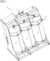
- figure 2 shows how figure 1 , modules A and D, but with in figure 2 the module D faces the viewer.
- the module D consists of three main air tanks 5, each with an internal volume of 250 liters.
- the main air tanks 5 are connected to one another via connecting lines 6, with a standard interface 7 being provided for the pneumatic connection of the main air tanks 5 to the rail vehicle or to other modules of the brake framework.
- the main air tanks 5 are circular-cylindrical and have an outside diameter of about 500 mm, so that the module D also has a depth of about 500 mm.
- Module A at the back of module D has a depth of 500 mm, so combining modules A and D gives a total depth of 1000 mm.
- all modules have the same height and same width.
- the width of the modules is expediently between 1 and 2 meters and the height is also between 1 and 2 meters.
- FIG. 12 shows a back-to-back perspective view of Modules C and B, with Module C facing the viewer.
- Module C consists of a compressor 8, a minimum pressure valve 9, a dryer 10, a filter 11, a condensate tank 12, a pantograph panel 13 and other components that are not listed here in an exhaustive manner.
- a pneumatic standard interface is again provided, which is used to connect further modules B or D or for the pneumatic connection of the rail vehicle.
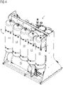
- figure 4 shows how figure 3 , the modules B and C in a perspective view and in a back-to-back arrangement, but in contrast to figure 3 the module B faces the viewer.
- module B consists of three main air tanks 14 and three auxiliary air tanks 15, each of which has an internal volume of 75 liters and is circular-cylindrical, with the hollow cylinders of the tanks having an outside diameter of approximately 300 mm.
- Module B thus has a depth of 300 mm, with module C having a depth of 700 mm.
- Connecting pipes 6 are again provided for connecting the main air tank and the auxiliary air tank.
- the modules C and B have the same width, expediently between 1 and 2 meters, and the same height H, expediently between 1 and 2 meters.
- the in the Figures 1 to 4 The modules shown are intended for placement on different sides of an aisle of an engine room of an electrically powered locomotive. Purely electrically powered locomotives usually have a central aisle.
- the brake frame according to the invention can be easily divided over different sides of the aisle due to the modular design.
- FIG. 5 shows modules A, B and C in a perspective view, with module A facing the viewer.
- Module C is arranged immediately behind module A, and module B is offset behind module B in the plane of the drawing.
- a common holding frame 16 for holding the respective modules can be seen.
- the modules A, B and C have common dimensions in the transverse direction and in the height, but the module B consists only of two main pressure vessels 14, which are located in the Fig figure 5 shown embodiment extend in the horizontal direction.
- the total depth of modules A, B and C is 1500 mm, with module A having a depth of 500 mm, module C having a depth of 700 mm and module B having a depth of 300 mm.
- Modules A, B and C assembled in this manner are intended for placement in the center of the engine room of a locomotive which is a diesel-electric powered two side gear locomotive.
- a diesel engine for driving a generator is arranged in the center of the machine room.
- FIG figure 6 shows the embodiment according to FIG figure 5 , but with the module C facing the viewer. Only the main pressure tanks 14 of module B can be seen, which, in contrast to the one in figure 5 shown embodiment extend in the vertical direction. Module A is placed in the plane of the drawing. According to the embodiment shown, modules B and C are nested in depth. Thus, the dryer 10 of the module 10 is located at the same depth as the main air tanks 14. Such nesting is appropriate when, for example, not five but only two compressed air tanks are required in module B, so that module B has sufficient space for components of other modules, here C. At this point, however, it should be pointed out once again that the components shown in the figures are only listed as examples. Within the scope of the invention, the modules can also have other components that are not shown or named here.
- figure 7 shows a further embodiment of a combination of the modules A, B and C, wherein the module A is again turned away from the viewer and placed in the plane of the drawing.
- the modules C and B are even more deep than in the exemplary embodiment figure 6 nested together.
- the main air reservoirs 14 of module B are arranged in the upper part of the common framework 16 above the compressor 8 of module C. the inside figure 7
- the condensate tank 12 that is not visible is mounted on the framework 16 behind the main air tanks 14 .
- Such a depth-shifted box arrangement is also possible according to the present invention. However, it is essential within the meaning of the invention that the dimensioning of the components does not exceed the standard dimensions of the modules.
- figure 8 shows a further exemplary embodiment of the device according to the invention, the two modules B and C being arranged back to back one behind the other.
- Module B faces the observer and, in this exemplary embodiment, has three vertical auxiliary pressure vessels 14 and a main pressure vessel 15 .
- Module C can be seen on the back and facing away from the viewer.
- an intake air duct 17 for the compressor of module C is attached to the frame 16.
- the intake air duct is a component of module B.
- FIG 9 the possible combinations of modules A, B and C or modified modules A'A", B', C', C" and D' are illustrated schematically.
- modules C, C', B and B' which each have the same dimensions as modules A, A', D and D' in the transverse and vertical directions.
- module D is arranged above the modules A, B and C.
- the module D is arranged inside the car body of a locomotive, for example under the roof of the rail vehicle. The same applies to the combinations of A', A", B', C', C" and D'.
Landscapes
- Engineering & Computer Science (AREA)
- Transportation (AREA)
- Mechanical Engineering (AREA)
- Automation & Control Theory (AREA)
- Electric Propulsion And Braking For Vehicles (AREA)
- Valves And Accessory Devices For Braking Systems (AREA)
- Braking Systems And Boosters (AREA)
- Braking Arrangements (AREA)
Priority Applications (1)
| Application Number | Priority Date | Filing Date | Title |
|---|---|---|---|
| PL09711308.8T PL2242672T5 (pl) | 2008-02-12 | 2009-02-09 | Modułowe urządzenie hamulcowe |
Applications Claiming Priority (2)
| Application Number | Priority Date | Filing Date | Title |
|---|---|---|---|
| DE102008009217A DE102008009217A1 (de) | 2008-02-12 | 2008-02-12 | Modulares Bremsgerüst |
| PCT/EP2009/051430 WO2009101042A2 (de) | 2008-02-12 | 2009-02-09 | Modulares bremsgerüst |
Publications (3)
| Publication Number | Publication Date |
|---|---|
| EP2242672A2 EP2242672A2 (de) | 2010-10-27 |
| EP2242672B1 EP2242672B1 (de) | 2018-12-19 |
| EP2242672B2 true EP2242672B2 (de) | 2022-10-05 |
Family
ID=40873978
Family Applications (1)
| Application Number | Title | Priority Date | Filing Date |
|---|---|---|---|
| EP09711308.8A Active EP2242672B2 (de) | 2008-02-12 | 2009-02-09 | Modulares bremsgerüst |
Country Status (8)
| Country | Link |
|---|---|
| US (1) | US8869951B2 (pl) |
| EP (1) | EP2242672B2 (pl) |
| CN (1) | CN101945792A (pl) |
| DE (1) | DE102008009217A1 (pl) |
| ES (1) | ES2715631T5 (pl) |
| PL (1) | PL2242672T5 (pl) |
| RU (1) | RU2507094C2 (pl) |
| WO (1) | WO2009101042A2 (pl) |
Families Citing this family (20)
| Publication number | Priority date | Publication date | Assignee | Title |
|---|---|---|---|---|
| DE102008048561A1 (de) * | 2008-09-23 | 2010-04-15 | Knorr-Bremse Systeme für Schienenfahrzeuge GmbH | Brems- sowie Zusatzgeräteanordnung einer pneumatischen Bremsanlage eines Fahrzeuges |
| WO2012135899A1 (en) * | 2011-04-06 | 2012-10-11 | Bradken Resources Pty Limited | Operational assembly for a rail wagon |
| CN102849084B (zh) * | 2011-06-28 | 2015-08-19 | 中国北车集团大同电力机车有限责任公司 | 电力机车气动柜和电力机车 |
| CN103419810B (zh) * | 2012-05-24 | 2015-11-04 | 中国北车集团大同电力机车有限责任公司 | 气动柜 |
| CN103511517B (zh) * | 2012-06-30 | 2015-12-16 | 南车戚墅堰机车车辆工艺研究所有限公司 | 蓄能式停放单元制动缸 |
| CN103661427B (zh) * | 2012-09-04 | 2016-03-23 | 中国北车集团大同电力机车有限责任公司 | 辅助供风装置及电力机车 |
| US9854702B2 (en) | 2014-01-15 | 2017-12-26 | Siemens Aktiengesellschaft | Compressed-air rack for an electric locomotive |
| DE102016000760A1 (de) | 2016-01-27 | 2017-07-27 | Siemens Aktiengesellschaft | Schaltung und Verteilerblock und aus diesen gebildete Bremssteueranordnung für Schienenfahrzeuge sowie Verteilersatz zum Konfigurieren und Verfahren zur Bildung der Bremssteueranordnung |
| DE102016117499A1 (de) * | 2016-09-16 | 2018-03-22 | Knorr-Bremse Systeme für Schienenfahrzeuge GmbH | Rahmen für eine Bremssteuereinrichtung eines schienengebundenen Fahrzeugs |
| DE102016117497A1 (de) * | 2016-09-16 | 2018-03-22 | Knorr-Bremse Systeme für Schienenfahrzeuge GmbH | Gerüstbalken für einen Rahmen einer Bremssteuereinrichtung eines schienengebundenen Fahrzeugs |
| AU2016423070B2 (en) * | 2016-09-16 | 2020-03-19 | New York Air Brake, LLC | Pneumatic configuration module for electronic air brake system |
| DE102016117501A1 (de) | 2016-09-16 | 2018-03-22 | Knorr-Bremse Systeme für Schienenfahrzeuge GmbH | Elektrische Einheit für ein schienengebundenes Fahrzeug |
| CN107336702B (zh) * | 2017-08-03 | 2023-07-14 | 眉山中车制动科技股份有限公司 | 轨道车辆用集成制动装置的连接结构及系统 |
| CN109383533B (zh) * | 2017-08-04 | 2020-05-15 | 中车大同电力机车有限公司 | 一种快装式可靠电气及机械连接装置 |
| CN108860122A (zh) * | 2018-07-05 | 2018-11-23 | 金龙联合汽车工业(苏州)有限公司 | 一种新型制动系统减振降噪模块化支架 |
| DE102018121215A1 (de) * | 2018-08-30 | 2020-03-05 | Man Truck & Bus Se | Druckluftmodul für ein Nutzfahrzeug und Verfahren zu dessen Prüfung |
| DE102020000730A1 (de) * | 2020-02-04 | 2021-08-05 | Man Truck & Bus Se | Druckluftmodul-Baukastensystem für ein Nutzfahrzeug |
| EP4117973A1 (en) * | 2020-03-10 | 2023-01-18 | Carlisle Industrial Brake&Friction | Modular electronic brake system |
| DE102020204742A1 (de) * | 2020-04-15 | 2021-10-21 | Siemens Mobility GmbH | Elektroschrank in einem Schienenfahrzeug |
| DE102024203390A1 (de) * | 2024-04-12 | 2025-10-16 | Siemens Mobility GmbH | Schrank-Körpernetz zum Aufbau eines Elektroschranks für ein Schienenfahrzeug |
Citations (4)
| Publication number | Priority date | Publication date | Assignee | Title |
|---|---|---|---|---|
| US5025734A (en) † | 1990-05-03 | 1991-06-25 | Westinghouse Air Brake Company | Locomotive equipment carriage |
| KR19990074977A (ko) † | 1998-03-16 | 1999-10-05 | 이재영 | 철도차량용 압축공기 발생장치 |
| US20040083893A1 (en) † | 2001-01-29 | 2004-05-06 | Sven-Olof Larsson | Modular air supply |
| WO2008025401A1 (de) † | 2006-08-31 | 2008-03-06 | Wabco Gmbh | Ventileinheit für eine elektropneumatische bremssteuerungseinrichtung |
Family Cites Families (10)
| Publication number | Priority date | Publication date | Assignee | Title |
|---|---|---|---|---|
| BR9401647A (pt) * | 1994-04-29 | 1995-11-21 | Ind Freios Knorr Ltda | Módulo de sistema de freio par veículo |
| DE19715528C2 (de) * | 1996-05-03 | 2003-04-24 | Knorr Bremse Systeme | Pneumatische Steuervorrichtung |
| US5743192A (en) * | 1996-10-17 | 1998-04-28 | Gunderson, Inc. | Railroad freight car for carrying motor vehicles |
| US6086163A (en) * | 1998-09-25 | 2000-07-11 | Tsm, Inc. | Electronic interface manifold adapter for railroad passenger cars |
| DE19908617A1 (de) * | 1999-02-27 | 2000-09-07 | Mak System Gmbh | Bremstafel zur Durchführung einer Bremssteuerung für Lokomotiven |
| FR2798345A1 (fr) | 1999-09-09 | 2001-03-16 | Renault Vehicules Ind | Centrale pneumatique, notamment pour vehicule industriel |
| RU46983U1 (ru) * | 2005-03-24 | 2005-08-10 | Открытое акционерное общество МТЗ ТРАНСМАШ | Исполнительная часть пневматической тормозной системы пассажирского локомотива |
| DE102006010723A1 (de) * | 2006-03-08 | 2007-09-13 | Knorr-Bremse Systeme für Schienenfahrzeuge GmbH | Kompressoranordnung |
| JP2007261533A (ja) * | 2006-03-29 | 2007-10-11 | West Japan Railway Co | 鉄道車両用装備品箱及びその換気方法 |
| US8894158B2 (en) * | 2007-12-26 | 2014-11-25 | New York Air Break Corporation | Unitized brake assembly |
-
2008
- 2008-02-12 DE DE102008009217A patent/DE102008009217A1/de not_active Withdrawn
-
2009
- 2009-02-09 EP EP09711308.8A patent/EP2242672B2/de active Active
- 2009-02-09 ES ES09711308T patent/ES2715631T5/es active Active
- 2009-02-09 WO PCT/EP2009/051430 patent/WO2009101042A2/de not_active Ceased
- 2009-02-09 RU RU2010137810/11A patent/RU2507094C2/ru active
- 2009-02-09 PL PL09711308.8T patent/PL2242672T5/pl unknown
- 2009-02-09 CN CN200980104974.1A patent/CN101945792A/zh active Pending
- 2009-02-09 US US12/867,085 patent/US8869951B2/en active Active
Patent Citations (4)
| Publication number | Priority date | Publication date | Assignee | Title |
|---|---|---|---|---|
| US5025734A (en) † | 1990-05-03 | 1991-06-25 | Westinghouse Air Brake Company | Locomotive equipment carriage |
| KR19990074977A (ko) † | 1998-03-16 | 1999-10-05 | 이재영 | 철도차량용 압축공기 발생장치 |
| US20040083893A1 (en) † | 2001-01-29 | 2004-05-06 | Sven-Olof Larsson | Modular air supply |
| WO2008025401A1 (de) † | 2006-08-31 | 2008-03-06 | Wabco Gmbh | Ventileinheit für eine elektropneumatische bremssteuerungseinrichtung |
Also Published As
| Publication number | Publication date |
|---|---|
| WO2009101042A2 (de) | 2009-08-20 |
| WO2009101042A3 (de) | 2010-04-15 |
| ES2715631T5 (es) | 2022-12-09 |
| ES2715631T3 (es) | 2019-06-05 |
| US20110031073A1 (en) | 2011-02-10 |
| DE102008009217A1 (de) | 2009-08-20 |
| RU2507094C2 (ru) | 2014-02-20 |
| PL2242672T5 (pl) | 2023-03-13 |
| CN101945792A (zh) | 2011-01-12 |
| PL2242672T3 (pl) | 2019-07-31 |
| US8869951B2 (en) | 2014-10-28 |
| EP2242672A2 (de) | 2010-10-27 |
| EP2242672B1 (de) | 2018-12-19 |
| RU2010137810A (ru) | 2012-03-20 |
Similar Documents
| Publication | Publication Date | Title |
|---|---|---|
| EP2242672B2 (de) | Modulares bremsgerüst | |
| DE202017103703U1 (de) | Elektrisch angetriebenes Hydrofoil | |
| EP3597515B1 (de) | Tragstrukturell und vorzugsweise funktionell modular aufgebautes nutzfahrzeug-chassis | |
| DE102018210699B4 (de) | Fahrzeug mit einem Elektroantrieb und einem Hybrid-Energiespeicher | |
| EP3615738B1 (de) | Hochgeschwindigkeitssystem zu unkrautbekämpfung | |
| DE102008048562A1 (de) | Ventilanordnung zur Brems- sowie Zusatzgeräteansteuerung einer pneumatischen Bremsanlage eines Fahrzeuges | |
| WO2013160062A1 (de) | Strukturstabile anordnung und verfahren zur bildung einer strukturstabilen anordnung | |
| DE102017200853A1 (de) | Hilfsrahmen für ein Kraftfahrzeug | |
| DE102019113699A1 (de) | Kraftfahrzeug mit einer Kraftfahrzeugkarosserie und einer Speicherzellenbaugruppe | |
| EP2663463B1 (de) | Lagerung eines achsgetriebes im heckbereich eines personenkraftwagens | |
| EP1495905A2 (de) | Flurförderzeug mit einem elektrischen Antrieb und einem Brennstoffzellensystem und Verfahren zum Betrieb eines Flurförderzeugs | |
| AT500533B1 (de) | Gas- oder trolleybus | |
| DE202016008429U1 (de) | Austauschbarer Tretantrieb für Elektrofahrräder | |
| WO2012116971A1 (de) | Schienenfahrzeug mit aufnahmeraum unterhalb des bodens | |
| DE102014112741A1 (de) | Kraftfahrzeug | |
| EP3640113A1 (de) | Energieaufnahmevorrichtung und schienenfahrzeug | |
| DE102011004603A1 (de) | Elektroflurförderzeug, insbesondere Gabelstapler | |
| DE102012017836A1 (de) | Fluidbehälter, insbesondere Hydrauliktank für ein Motor-Pumpen-Aggregat | |
| DE202008008246U1 (de) | Schienenfahreinrichtung | |
| EP2314160A1 (de) | Selbstfahrende Pflanzenschutzspritze mit mehreren Flüssigkeitstanks | |
| DE102005057120B4 (de) | Befestigung eines schweren Gerätes an der Tragstruktur eines Schienenfahrzeuges | |
| DE102013021253B3 (de) | Kraftfahrzeug mit einem speziell ausgebildeten und angeordneten Betriebsmittelbehälter | |
| DE457943C (de) | Bremseinrichtung, insbesondere fuer Kraftfahrzeuge | |
| EP3292034B1 (de) | Sanitäreinrichtungen in zügen | |
| EP2879932B1 (de) | Hilfsaggregategerüst für eine elektrolokomotive |
Legal Events
| Date | Code | Title | Description |
|---|---|---|---|
| PUAI | Public reference made under article 153(3) epc to a published international application that has entered the european phase |
Free format text: ORIGINAL CODE: 0009012 |
|
| 17P | Request for examination filed |
Effective date: 20100708 |
|
| AK | Designated contracting states |
Kind code of ref document: A2 Designated state(s): AT BE BG CH CY CZ DE DK EE ES FI FR GB GR HR HU IE IS IT LI LT LU LV MC MK MT NL NO PL PT RO SE SI SK TR |
|
| AX | Request for extension of the european patent |
Extension state: AL BA RS |
|
| DAX | Request for extension of the european patent (deleted) | ||
| RAP1 | Party data changed (applicant data changed or rights of an application transferred) |
Owner name: SIEMENS AKTIENGESELLSCHAFT |
|
| RAP1 | Party data changed (applicant data changed or rights of an application transferred) |
Owner name: SIEMENS AKTIENGESELLSCHAFT |
|
| STAA | Information on the status of an ep patent application or granted ep patent |
Free format text: STATUS: EXAMINATION IS IN PROGRESS |
|
| 17Q | First examination report despatched |
Effective date: 20171208 |
|
| GRAP | Despatch of communication of intention to grant a patent |
Free format text: ORIGINAL CODE: EPIDOSNIGR1 |
|
| STAA | Information on the status of an ep patent application or granted ep patent |
Free format text: STATUS: GRANT OF PATENT IS INTENDED |
|
| INTG | Intention to grant announced |
Effective date: 20180725 |
|
| RAP1 | Party data changed (applicant data changed or rights of an application transferred) |
Owner name: SIEMENS MOBILITY GMBH |
|
| GRAS | Grant fee paid |
Free format text: ORIGINAL CODE: EPIDOSNIGR3 |
|
| GRAA | (expected) grant |
Free format text: ORIGINAL CODE: 0009210 |
|
| STAA | Information on the status of an ep patent application or granted ep patent |
Free format text: STATUS: THE PATENT HAS BEEN GRANTED |
|
| AK | Designated contracting states |
Kind code of ref document: B1 Designated state(s): AT BE BG CH CY CZ DE DK EE ES FI FR GB GR HR HU IE IS IT LI LT LU LV MC MK MT NL NO PL PT RO SE SI SK TR |
|
| REG | Reference to a national code |
Ref country code: GB Ref legal event code: FG4D Free format text: NOT ENGLISH |
|
| REG | Reference to a national code |
Ref country code: CH Ref legal event code: EP |
|
| REG | Reference to a national code |
Ref country code: DE Ref legal event code: R096 Ref document number: 502009015518 Country of ref document: DE |
|
| REG | Reference to a national code |
Ref country code: IE Ref legal event code: FG4D Free format text: LANGUAGE OF EP DOCUMENT: GERMAN |
|
| REG | Reference to a national code |
Ref country code: AT Ref legal event code: REF Ref document number: 1078338 Country of ref document: AT Kind code of ref document: T Effective date: 20190115 |
|
| REG | Reference to a national code |
Ref country code: CH Ref legal event code: NV Representative=s name: SIEMENS SCHWEIZ AG, CH |
|
| REG | Reference to a national code |
Ref country code: NL Ref legal event code: MP Effective date: 20181219 |
|
| PG25 | Lapsed in a contracting state [announced via postgrant information from national office to epo] |
Ref country code: FI Free format text: LAPSE BECAUSE OF FAILURE TO SUBMIT A TRANSLATION OF THE DESCRIPTION OR TO PAY THE FEE WITHIN THE PRESCRIBED TIME-LIMIT Effective date: 20181219 Ref country code: NO Free format text: LAPSE BECAUSE OF FAILURE TO SUBMIT A TRANSLATION OF THE DESCRIPTION OR TO PAY THE FEE WITHIN THE PRESCRIBED TIME-LIMIT Effective date: 20190319 Ref country code: LV Free format text: LAPSE BECAUSE OF FAILURE TO SUBMIT A TRANSLATION OF THE DESCRIPTION OR TO PAY THE FEE WITHIN THE PRESCRIBED TIME-LIMIT Effective date: 20181219 Ref country code: BG Free format text: LAPSE BECAUSE OF FAILURE TO SUBMIT A TRANSLATION OF THE DESCRIPTION OR TO PAY THE FEE WITHIN THE PRESCRIBED TIME-LIMIT Effective date: 20190319 Ref country code: LT Free format text: LAPSE BECAUSE OF FAILURE TO SUBMIT A TRANSLATION OF THE DESCRIPTION OR TO PAY THE FEE WITHIN THE PRESCRIBED TIME-LIMIT Effective date: 20181219 Ref country code: HR Free format text: LAPSE BECAUSE OF FAILURE TO SUBMIT A TRANSLATION OF THE DESCRIPTION OR TO PAY THE FEE WITHIN THE PRESCRIBED TIME-LIMIT Effective date: 20181219 |
|
| REG | Reference to a national code |
Ref country code: LT Ref legal event code: MG4D |
|
| PG25 | Lapsed in a contracting state [announced via postgrant information from national office to epo] |
Ref country code: SE Free format text: LAPSE BECAUSE OF FAILURE TO SUBMIT A TRANSLATION OF THE DESCRIPTION OR TO PAY THE FEE WITHIN THE PRESCRIBED TIME-LIMIT Effective date: 20181219 Ref country code: GR Free format text: LAPSE BECAUSE OF FAILURE TO SUBMIT A TRANSLATION OF THE DESCRIPTION OR TO PAY THE FEE WITHIN THE PRESCRIBED TIME-LIMIT Effective date: 20190320 |
|
| REG | Reference to a national code |
Ref country code: ES Ref legal event code: FG2A Ref document number: 2715631 Country of ref document: ES Kind code of ref document: T3 Effective date: 20190605 |
|
| PG25 | Lapsed in a contracting state [announced via postgrant information from national office to epo] |
Ref country code: NL Free format text: LAPSE BECAUSE OF FAILURE TO SUBMIT A TRANSLATION OF THE DESCRIPTION OR TO PAY THE FEE WITHIN THE PRESCRIBED TIME-LIMIT Effective date: 20181219 |
|
| PG25 | Lapsed in a contracting state [announced via postgrant information from national office to epo] |
Ref country code: PT Free format text: LAPSE BECAUSE OF FAILURE TO SUBMIT A TRANSLATION OF THE DESCRIPTION OR TO PAY THE FEE WITHIN THE PRESCRIBED TIME-LIMIT Effective date: 20190419 |
|
| PG25 | Lapsed in a contracting state [announced via postgrant information from national office to epo] |
Ref country code: IS Free format text: LAPSE BECAUSE OF FAILURE TO SUBMIT A TRANSLATION OF THE DESCRIPTION OR TO PAY THE FEE WITHIN THE PRESCRIBED TIME-LIMIT Effective date: 20190419 Ref country code: EE Free format text: LAPSE BECAUSE OF FAILURE TO SUBMIT A TRANSLATION OF THE DESCRIPTION OR TO PAY THE FEE WITHIN THE PRESCRIBED TIME-LIMIT Effective date: 20181219 Ref country code: RO Free format text: LAPSE BECAUSE OF FAILURE TO SUBMIT A TRANSLATION OF THE DESCRIPTION OR TO PAY THE FEE WITHIN THE PRESCRIBED TIME-LIMIT Effective date: 20181219 Ref country code: SK Free format text: LAPSE BECAUSE OF FAILURE TO SUBMIT A TRANSLATION OF THE DESCRIPTION OR TO PAY THE FEE WITHIN THE PRESCRIBED TIME-LIMIT Effective date: 20181219 |
|
| REG | Reference to a national code |
Ref country code: DE Ref legal event code: R026 Ref document number: 502009015518 Country of ref document: DE |
|
| PLBI | Opposition filed |
Free format text: ORIGINAL CODE: 0009260 |
|
| PLAX | Notice of opposition and request to file observation + time limit sent |
Free format text: ORIGINAL CODE: EPIDOSNOBS2 |
|
| 26 | Opposition filed |
Opponent name: KNORR-BREMSE SYSTEME FUER SCHIENENFAHRZEUGE GMBH Effective date: 20190919 |
|
| PG25 | Lapsed in a contracting state [announced via postgrant information from national office to epo] |
Ref country code: LU Free format text: LAPSE BECAUSE OF NON-PAYMENT OF DUE FEES Effective date: 20190209 Ref country code: MC Free format text: LAPSE BECAUSE OF FAILURE TO SUBMIT A TRANSLATION OF THE DESCRIPTION OR TO PAY THE FEE WITHIN THE PRESCRIBED TIME-LIMIT Effective date: 20181219 Ref country code: DK Free format text: LAPSE BECAUSE OF FAILURE TO SUBMIT A TRANSLATION OF THE DESCRIPTION OR TO PAY THE FEE WITHIN THE PRESCRIBED TIME-LIMIT Effective date: 20181219 |
|
| REG | Reference to a national code |
Ref country code: BE Ref legal event code: MM Effective date: 20190228 |
|
| GBPC | Gb: european patent ceased through non-payment of renewal fee |
Effective date: 20190319 |
|
| REG | Reference to a national code |
Ref country code: IE Ref legal event code: MM4A |
|
| PG25 | Lapsed in a contracting state [announced via postgrant information from national office to epo] |
Ref country code: IE Free format text: LAPSE BECAUSE OF NON-PAYMENT OF DUE FEES Effective date: 20190209 Ref country code: GB Free format text: LAPSE BECAUSE OF NON-PAYMENT OF DUE FEES Effective date: 20190319 |
|
| PLBB | Reply of patent proprietor to notice(s) of opposition received |
Free format text: ORIGINAL CODE: EPIDOSNOBS3 |
|
| PG25 | Lapsed in a contracting state [announced via postgrant information from national office to epo] |
Ref country code: SI Free format text: LAPSE BECAUSE OF FAILURE TO SUBMIT A TRANSLATION OF THE DESCRIPTION OR TO PAY THE FEE WITHIN THE PRESCRIBED TIME-LIMIT Effective date: 20181219 Ref country code: BE Free format text: LAPSE BECAUSE OF NON-PAYMENT OF DUE FEES Effective date: 20190228 |
|
| PG25 | Lapsed in a contracting state [announced via postgrant information from national office to epo] |
Ref country code: TR Free format text: LAPSE BECAUSE OF FAILURE TO SUBMIT A TRANSLATION OF THE DESCRIPTION OR TO PAY THE FEE WITHIN THE PRESCRIBED TIME-LIMIT Effective date: 20181219 |
|
| REG | Reference to a national code |
Ref country code: AT Ref legal event code: MM01 Ref document number: 1078338 Country of ref document: AT Kind code of ref document: T Effective date: 20190209 |
|
| PG25 | Lapsed in a contracting state [announced via postgrant information from national office to epo] |
Ref country code: AT Free format text: LAPSE BECAUSE OF NON-PAYMENT OF DUE FEES Effective date: 20190209 |
|
| PG25 | Lapsed in a contracting state [announced via postgrant information from national office to epo] |
Ref country code: MT Free format text: LAPSE BECAUSE OF FAILURE TO SUBMIT A TRANSLATION OF THE DESCRIPTION OR TO PAY THE FEE WITHIN THE PRESCRIBED TIME-LIMIT Effective date: 20181219 |
|
| PGFP | Annual fee paid to national office [announced via postgrant information from national office to epo] |
Ref country code: IT Payment date: 20210219 Year of fee payment: 13 |
|
| PG25 | Lapsed in a contracting state [announced via postgrant information from national office to epo] |
Ref country code: CY Free format text: LAPSE BECAUSE OF FAILURE TO SUBMIT A TRANSLATION OF THE DESCRIPTION OR TO PAY THE FEE WITHIN THE PRESCRIBED TIME-LIMIT Effective date: 20181219 |
|
| PG25 | Lapsed in a contracting state [announced via postgrant information from national office to epo] |
Ref country code: HU Free format text: LAPSE BECAUSE OF FAILURE TO SUBMIT A TRANSLATION OF THE DESCRIPTION OR TO PAY THE FEE WITHIN THE PRESCRIBED TIME-LIMIT; INVALID AB INITIO Effective date: 20090209 |
|
| PLBP | Opposition withdrawn |
Free format text: ORIGINAL CODE: 0009264 |
|
| PG25 | Lapsed in a contracting state [announced via postgrant information from national office to epo] |
Ref country code: MK Free format text: LAPSE BECAUSE OF FAILURE TO SUBMIT A TRANSLATION OF THE DESCRIPTION OR TO PAY THE FEE WITHIN THE PRESCRIBED TIME-LIMIT Effective date: 20181219 |
|
| PUAH | Patent maintained in amended form |
Free format text: ORIGINAL CODE: 0009272 |
|
| STAA | Information on the status of an ep patent application or granted ep patent |
Free format text: STATUS: PATENT MAINTAINED AS AMENDED |
|
| 27A | Patent maintained in amended form |
Effective date: 20221005 |
|
| AK | Designated contracting states |
Kind code of ref document: B2 Designated state(s): AT BE BG CH CY CZ DE DK EE ES FI FR GB GR HR HU IE IS IT LI LT LU LV MC MK MT NL NO PL PT RO SE SI SK TR |
|
| REG | Reference to a national code |
Ref country code: DE Ref legal event code: R102 Ref document number: 502009015518 Country of ref document: DE |
|
| REG | Reference to a national code |
Ref country code: ES Ref legal event code: DC2A Ref document number: 2715631 Country of ref document: ES Kind code of ref document: T5 Effective date: 20221209 |
|
| PG25 | Lapsed in a contracting state [announced via postgrant information from national office to epo] |
Ref country code: IT Free format text: LAPSE BECAUSE OF NON-PAYMENT OF DUE FEES Effective date: 20220209 |
|
| PGFP | Annual fee paid to national office [announced via postgrant information from national office to epo] |
Ref country code: DE Payment date: 20230419 Year of fee payment: 15 Ref country code: CH Payment date: 20230504 Year of fee payment: 15 |
|
| PGFP | Annual fee paid to national office [announced via postgrant information from national office to epo] |
Ref country code: CZ Payment date: 20240205 Year of fee payment: 16 |
|
| REG | Reference to a national code |
Ref country code: DE Ref legal event code: R119 Ref document number: 502009015518 Country of ref document: DE |
|
| REG | Reference to a national code |
Ref country code: CH Ref legal event code: PL |
|
| PG25 | Lapsed in a contracting state [announced via postgrant information from national office to epo] |
Ref country code: CH Free format text: LAPSE BECAUSE OF NON-PAYMENT OF DUE FEES Effective date: 20240229 |
|
| PG25 | Lapsed in a contracting state [announced via postgrant information from national office to epo] |
Ref country code: CH Free format text: LAPSE BECAUSE OF NON-PAYMENT OF DUE FEES Effective date: 20240229 |
|
| PG25 | Lapsed in a contracting state [announced via postgrant information from national office to epo] |
Ref country code: DE Free format text: LAPSE BECAUSE OF NON-PAYMENT OF DUE FEES Effective date: 20240903 |
|
| PG25 | Lapsed in a contracting state [announced via postgrant information from national office to epo] |
Ref country code: DE Free format text: LAPSE BECAUSE OF NON-PAYMENT OF DUE FEES Effective date: 20240903 |
|
| PGFP | Annual fee paid to national office [announced via postgrant information from national office to epo] |
Ref country code: ES Payment date: 20250520 Year of fee payment: 17 |
|
| PG25 | Lapsed in a contracting state [announced via postgrant information from national office to epo] |
Ref country code: CZ Free format text: LAPSE BECAUSE OF NON-PAYMENT OF DUE FEES Effective date: 20250209 |
|
| PGFP | Annual fee paid to national office [announced via postgrant information from national office to epo] |
Ref country code: FR Payment date: 20260213 Year of fee payment: 18 |
|
| PGFP | Annual fee paid to national office [announced via postgrant information from national office to epo] |
Ref country code: PL Payment date: 20260129 Year of fee payment: 18 |