EP2242923B1 - Freistehende, tauchende wasserturbine mit einem axialrotor - Google Patents
Freistehende, tauchende wasserturbine mit einem axialrotor Download PDFInfo
- Publication number
- EP2242923B1 EP2242923B1 EP09706561.9A EP09706561A EP2242923B1 EP 2242923 B1 EP2242923 B1 EP 2242923B1 EP 09706561 A EP09706561 A EP 09706561A EP 2242923 B1 EP2242923 B1 EP 2242923B1
- Authority
- EP
- European Patent Office
- Prior art keywords
- turbine
- power generation
- generation plant
- support structure
- axial
- Prior art date
- Legal status (The legal status is an assumption and is not a legal conclusion. Google has not performed a legal analysis and makes no representation as to the accuracy of the status listed.)
- Not-in-force
Links
Images
Classifications
-
- F—MECHANICAL ENGINEERING; LIGHTING; HEATING; WEAPONS; BLASTING
- F03—MACHINES OR ENGINES FOR LIQUIDS; WIND, SPRING, OR WEIGHT MOTORS; PRODUCING MECHANICAL POWER OR A REACTIVE PROPULSIVE THRUST, NOT OTHERWISE PROVIDED FOR
- F03B—MACHINES OR ENGINES FOR LIQUIDS
- F03B3/00—Machines or engines of reaction type; Parts or details peculiar thereto
- F03B3/04—Machines or engines of reaction type; Parts or details peculiar thereto with substantially axial flow throughout rotors, e.g. propeller turbines
-
- F—MECHANICAL ENGINEERING; LIGHTING; HEATING; WEAPONS; BLASTING
- F03—MACHINES OR ENGINES FOR LIQUIDS; WIND, SPRING, OR WEIGHT MOTORS; PRODUCING MECHANICAL POWER OR A REACTIVE PROPULSIVE THRUST, NOT OTHERWISE PROVIDED FOR
- F03B—MACHINES OR ENGINES FOR LIQUIDS
- F03B13/00—Adaptations of machines or engines for special use; Combinations of machines or engines with driving or driven apparatus; Power stations or aggregates
- F03B13/12—Adaptations of machines or engines for special use; Combinations of machines or engines with driving or driven apparatus; Power stations or aggregates characterised by using wave or tide energy
- F03B13/26—Adaptations of machines or engines for special use; Combinations of machines or engines with driving or driven apparatus; Power stations or aggregates characterised by using wave or tide energy using tide energy
-
- F—MECHANICAL ENGINEERING; LIGHTING; HEATING; WEAPONS; BLASTING
- F03—MACHINES OR ENGINES FOR LIQUIDS; WIND, SPRING, OR WEIGHT MOTORS; PRODUCING MECHANICAL POWER OR A REACTIVE PROPULSIVE THRUST, NOT OTHERWISE PROVIDED FOR
- F03B—MACHINES OR ENGINES FOR LIQUIDS
- F03B17/00—Other machines or engines
- F03B17/06—Other machines or engines using liquid flow with predominantly kinetic energy conversion, e.g. of swinging-flap type, "run-of-river", "ultra-low head"
- F03B17/061—Other machines or engines using liquid flow with predominantly kinetic energy conversion, e.g. of swinging-flap type, "run-of-river", "ultra-low head" with rotation axis substantially in flow direction
-
- F—MECHANICAL ENGINEERING; LIGHTING; HEATING; WEAPONS; BLASTING
- F03—MACHINES OR ENGINES FOR LIQUIDS; WIND, SPRING, OR WEIGHT MOTORS; PRODUCING MECHANICAL POWER OR A REACTIVE PROPULSIVE THRUST, NOT OTHERWISE PROVIDED FOR
- F03B—MACHINES OR ENGINES FOR LIQUIDS
- F03B3/00—Machines or engines of reaction type; Parts or details peculiar thereto
- F03B3/12—Blades; Blade-carrying rotors
- F03B3/126—Rotors for essentially axial flow, e.g. for propeller turbines
-
- E—FIXED CONSTRUCTIONS
- E02—HYDRAULIC ENGINEERING; FOUNDATIONS; SOIL SHIFTING
- E02B—HYDRAULIC ENGINEERING
- E02B17/00—Artificial islands mounted on piles or like supports, e.g. platforms on raisable legs or offshore constructions; Construction methods therefor
- E02B2017/0091—Offshore structures for wind turbines
-
- F—MECHANICAL ENGINEERING; LIGHTING; HEATING; WEAPONS; BLASTING
- F05—INDEXING SCHEMES RELATING TO ENGINES OR PUMPS IN VARIOUS SUBCLASSES OF CLASSES F01-F04
- F05B—INDEXING SCHEME RELATING TO WIND, SPRING, WEIGHT, INERTIA OR LIKE MOTORS, TO MACHINES OR ENGINES FOR LIQUIDS COVERED BY SUBCLASSES F03B, F03D AND F03G
- F05B2240/00—Components
- F05B2240/90—Mounting on supporting structures or systems
- F05B2240/97—Mounting on supporting structures or systems on a submerged structure
-
- F—MECHANICAL ENGINEERING; LIGHTING; HEATING; WEAPONS; BLASTING
- F05—INDEXING SCHEMES RELATING TO ENGINES OR PUMPS IN VARIOUS SUBCLASSES OF CLASSES F01-F04
- F05B—INDEXING SCHEME RELATING TO WIND, SPRING, WEIGHT, INERTIA OR LIKE MOTORS, TO MACHINES OR ENGINES FOR LIQUIDS COVERED BY SUBCLASSES F03B, F03D AND F03G
- F05B2250/00—Geometry
- F05B2250/70—Shape
- F05B2250/71—Shape curved
-
- Y—GENERAL TAGGING OF NEW TECHNOLOGICAL DEVELOPMENTS; GENERAL TAGGING OF CROSS-SECTIONAL TECHNOLOGIES SPANNING OVER SEVERAL SECTIONS OF THE IPC; TECHNICAL SUBJECTS COVERED BY FORMER USPC CROSS-REFERENCE ART COLLECTIONS [XRACs] AND DIGESTS
- Y02—TECHNOLOGIES OR APPLICATIONS FOR MITIGATION OR ADAPTATION AGAINST CLIMATE CHANGE
- Y02E—REDUCTION OF GREENHOUSE GAS [GHG] EMISSIONS, RELATED TO ENERGY GENERATION, TRANSMISSION OR DISTRIBUTION
- Y02E10/00—Energy generation through renewable energy sources
- Y02E10/20—Hydro energy
-
- Y—GENERAL TAGGING OF NEW TECHNOLOGICAL DEVELOPMENTS; GENERAL TAGGING OF CROSS-SECTIONAL TECHNOLOGIES SPANNING OVER SEVERAL SECTIONS OF THE IPC; TECHNICAL SUBJECTS COVERED BY FORMER USPC CROSS-REFERENCE ART COLLECTIONS [XRACs] AND DIGESTS
- Y02—TECHNOLOGIES OR APPLICATIONS FOR MITIGATION OR ADAPTATION AGAINST CLIMATE CHANGE
- Y02E—REDUCTION OF GREENHOUSE GAS [GHG] EMISSIONS, RELATED TO ENERGY GENERATION, TRANSMISSION OR DISTRIBUTION
- Y02E10/00—Energy generation through renewable energy sources
- Y02E10/30—Energy from the sea, e.g. using wave energy or salinity gradient
Definitions
- the invention relates to a diving, freestanding power plant with a water turbine, which is created as an axial turbine with propeller-shaped shape.
- Power generation plants which extract energy from a stream of water as free-standing units without additional dam structures, can be used as river water power plants and in particular for the production of energy from a sea current, preferably a tidal current.
- Dipping power plants with a support structure on which a water turbine in the form of an axial turbine rotates are known.
- the axial turbine includes a hub with attached, propeller-shaped turbine blades.
- Such an axial turbine is in rotationally fixed connection to a drive shaft mounted in a nacelle housing, which usually serves to drive an electric generator.
- the turbine blades are arranged in the form of radial jet rotors along the circumference of a hub, ie it can be defined for each of the turbine blades at least one Auffädelline the profile sections, which is rectilinear and has in the radial direction in relation to the axis of rotation of the axial turbine.
- Such a design of the turbine blades is characterized by high structural strength and is therefore preferred for diving in comparison with an air flow high density of water as a driving medium for diving power plants. Even with radially small axial turbines for diving power plants, a high torque is absorbed so that the entire system must be designed from the turbine blades to the support structure according to the high static and dynamic loads.
- the invention has for its object to provide a freestanding, diving power generation plant, which is designed so that only limited dynamic load from the axial turbine and the entire system can be designed structurally simple, especially in terms of structural strength.
- the invention for a first embodiment is distinguished by turbine blades of an axial turbine for a diving power generation plant, for which the projection of the threading line of the profile sections into the plane of rotation does not exclusively point in the radial direction or deviate from the course of the radial jet. This deviation leads, at least in subregions of the threading line, to a radius-dependent angular offset with respect to the radial jet.
- the threading line of the profile cuts is led out of the plane of rotation, the turbine blade tip being farther from the support structure than the base point of the turbine blade. This can be done curved.
- the term "plane of rotation" of the axial turbine is understood to mean a plane to which the axis of rotation forms a surface normal and which intersects the root of at least one turbine blade.
- the foot point is defined as a section of the threading line with the support structure of the turbine blade, typically a hub.
- the threading line represents the connecting line of a defined point of the profile sections of a turbine blade.
- a point defined in this way can be, for example, the intersection of the skeleton line with the center line of the profile section.
- the Auffädellinem that point on the skeleton line is selected, which is at a quarter of the tread depth. For a variety of profiles, this point approximates the torque-free one Force application point.
- the geometrical condition of a deviation from the radial beam path in the plane of rotation should be given for every possible definition of the threading line.
- each of the turbine blades does not traverse the area in the flow field affected by the support structure with the total turbine blade extension at the same time. Instead, this area of influence for a turbine blade is traversed at different times according to its shape reaching into the space, which reduces momentary shocks occurring in the pulse.
- a deviation of the projection of the axle line into the plane of rotation is applied, which effectively reduces pressure pulses.
- the degree of inclination and / or curvature of the projection of the threading line against the radials will depend on several factors - these are, in particular, the flow velocity, the dimension of the support structure, and the number, extension and size of the turbine blades.
- a minimum angular deviation of at least 10 ° will be present for the region of the greatest forward or backward position against the radial jet.
- the angular deviation between the radial beam and a straight line is measured, which is determined by the belonging to the respective profile section point on the Auffädelline and the piercing point of the axis of rotation by the rotation planes.
- embodiments are conceivable for which there is a supply or reserve with respect to the radial jet only over part of the longitudinal extension of the turbine blade. It is preferred to provide the curvature and / or inclination of the threading line for at least one third of the longitudinal extent, with the area of the turbine blade tips being the most influential.
- a nacelle housing is provided between the hub of the axial turbine and the support structure, are housed in the transmission and generator components.
- the nacelle housing is designed to be axially elongated and comprises an axial Spacer.
- the support structure can be applied streamlined at least in part. In the case of a support structure in the form of a tower, it makes sense to form the cross section asymmetric. In this case, in particular elliptical or tapered at both axial ends cross-sections into consideration.
- a noise reduction is given with the turbine blade geometry according to the invention for a rotationally symmetrical support structure.
- a support structure can be given for example for a floating in the water and anchored with a cable system design.
- the upstream region is then influenced substantially symmetrically, while in the wake of the instabilities present there, the problems described above are still present.
- the sound generation is reduced by a differently selected from turbine blade to turbine blade Auffädellinienverlauf for an axial turbine with a plurality of turbine blades, it is therefore for this embodiment variant in the circumferential direction before a symmetry break with respect to the turbine blade geometries.
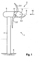
- FIG. 1 shows a schematic simplified perspective view of an inventive, diving power plant 1.
- This generically includes a water turbine, which is designed as an axial turbine 2.
- an axial turbine 2 with three turbine blades 3.1, 3.2, 3.3 is used, which are arranged along the peripheral surface of a hub 4 at an angular distance of 120 °.
- the axial turbine 2 runs together with the hood 6 on the nacelle housing.
- FIG. 1 apparent drive shaft in torsionally rigid connection to the axial turbine 2.
- the drive shaft transmits the driving torque at least indirectly to an electric generator (not shown).
- the nacelle housing 5 is fixed to a support structure 7, which is fundamental for the illustrated embodiment as a cylindrical tower on the body of water 8.
- a support structure 7 is used in a generalized manner and can also designate a buoyant unit with which the axial turbine 2 is at least indirectly connected.
- the support structure 7 is a flow obstacle and builds for a windward according to FIG. 1 in the upstream direction on a Turmvorstau. Each time the turbine blades pass through this tower prow, a pressure pulse is created.
- a corresponding problem exists for a Lee13r, here is the support structure with respect to the plane of rotation of the axial turbine 2 upstream, so that a tower shadow is created. In this case, the flow velocity falls locally in the tower shadow or the flow is otherwise influenced by the support structure 7; in the problematic case, an unsteady flow in the form of a vortex street arises.
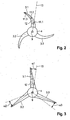
- the turbine blades 3.1, 3.2, 3.3 for an axial turbine 2 of a submersible power generation plant 1 according to the invention deviate along the longitudinal extension with respect to the projection into the plane of rotation from the radial direction.
- This is for two exemplary designs in the FIGS. 2 and 3 shown.
- the radial beam 13 is regarded as the radial leading to the direction of the axis of rotation 9 through the base point of the respective turbine blade.
- the turbine blades 3.1, 3.2, 3.3 for the projection on the plane of rotation a crescent-shaped course of Auffädelline 12.
- the Auffädelline 12 may have an additional directional component, which points in the normal direction to the plane of rotation of the axial turbine 2.
- the profile sections may be of any shape, in particular, the profiles of the three-digit Göttinger profile family come into consideration, wherein the profile profile of the turbine blades 3.1, 3.2, 3.3 can be configured as a wing profile. It is also conceivable to use a bidirectionally inflowable profile, in particular a point-symmetrical. In addition, the turbine blades, respectively their profile sections, occupy a predetermined angular position to the direction of flow 10. Furthermore, it is conceivable to form the turbine blades 3.1, 3.2, 3.3 rotationally rigidly connected to the hub or to associate them with an angle adjustment mechanism (pitch).
- an angle adjustment mechanism pitch
- FIG. 3 an embodiment of the invention is shown, for the course of a Auffädelline 12 of the turbine blades 3.1, 3.2, 3.3 in contrast to the embodiment according to FIG. 2 for the projection in the plane of rotation not sickle-shaped, but is straight-lined.
- the course of Auffädelline 12 has an angular deviation from the radial direction, which in FIG. 3 is illustrated for the respective turbine blades by the reference numerals ⁇ 1, ⁇ 2 and ⁇ 3.
- the angular deviations from the radial beam ⁇ 1, ⁇ 2, ⁇ 3 differ from one another, so that a symmetry operation is applied in the circumferential direction.
- the radially outer region of the turbine blades 3.1, 3.2, 3.3 is designed so that in the event of cavitation bubbles arising, they are guided over a reduced area of the turbine blades, so as to limit the damage potential.
- this is achieved by a curving or Abwirikeln the trailing edge of the rotor blades in the direction of rotation, d. H. the Auffädelline runs in the radially outer region of the radial beam ahead.
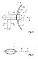
- the deviation of the course of the threading line 12 with respect to the radial direction may be a turbine blade from the plane of rotation 15 of the axial turbine 2 lead out.
- An example of such a design is in longitudinal section through a submersible power generation plant according to the invention FIG. 4 shown.
- a crescent-shaped course of the threading line can be seen in a plane which is predetermined by the radial direction 13 and the axis of rotation 9. Accordingly, the outer ends of the turbine blades 3.1, 3.2 jump forward or backward relative to the plane of rotation.
- the ends of the turbine blades 3.1, 3.2 upstream so that in particular the fast rotating parts of the turbine blades 3.1, 3.2, namely the turbine blade tips, a further distance in the direction of the axis of rotation of the axial turbine 2 of the support structure 7 than the near-hub areas. Consequently, the turbine blades 3.1, 3.2 traverse along their longitudinal extent at a predetermined time the area of the turret advance over a certain axial distance, wherein the turbine blade tip engages in a region of lesser influence by the support structure 7. As a result, the pressure pulses generated by the Turmvorstau can be further mitigated.
- elliptical or otherwise flattened cross sections in question so that the upstream nose of the Cross-section causes a low flow resistance and the Strömungsaustauf downstream is disturbed as low as possible.
Landscapes
- Engineering & Computer Science (AREA)
- Chemical & Material Sciences (AREA)
- Combustion & Propulsion (AREA)
- Mechanical Engineering (AREA)
- General Engineering & Computer Science (AREA)
- Power Engineering (AREA)
- Life Sciences & Earth Sciences (AREA)
- General Life Sciences & Earth Sciences (AREA)
- Oceanography (AREA)
- Other Liquid Machine Or Engine Such As Wave Power Use (AREA)
- Hydraulic Turbines (AREA)
Description
- Die Erfindung betrifft eine tauchende, freistehende Energieerzeugungsanlage mit einer Wasserturbine, die als Axialturbine mit propellerförmiger Gestalt angelegt ist.
- Energieerzeugungsanlagen, die als freistehende Einheiten ohne zusätzliche Dammstrukturen Energie aus einer Gewässerströmung entnehmen, können als Flusswasserkraftwerke und insbesondere zur Gewinnung von Energie aus einer Meeresströmung, vorzugsweise einer Gezeitenströmung, Verwendung finden.
- Tauchende Energieerzeugungsanlagen mit einer Stützstruktur, an der eine Wasserturbine in Form einer Axialturbine umläuft, sind bekannt. Üblicherweise umfasst die Axialturbine eine Nabe mit daran angebrachten, propellerförmigen Turbinenblättern. Eine solche Axialturbine steht in drehfester Verbindung zu einer in einem Gondelgehäuse gelagerten Antriebswelle, die üblicherweise zum Antrieb eines elektrischen Generators dient.
- Für gattungsgemäß freistehende, tauchende Energieerzeugungsanlagen wird exemplarisch auf die
EP 1 183 463 A1 und dieEP 1 540 172 A1 verwiesen. Aus diesen Druckschriften sind propellerförmige Axialturbinen bekannt. Dabei sind die Turbinenblätter in Form von Radialstrahlrotoren entlang des Umfangs einer Nabe angeordnet, d. h. es lässt sich für jedes der Turbinenblätter wenigstens eine Auffädellinie der Profilschnitte definieren, die geradlinig verläuft und im Verhältnis zur Drehachse der Axialturbine in radiale Richtung weist. Eine solche Gestaltung der Turbinenblätter zeichnet sich durch hohe Strukturfestigkeit aus und wird daher für die im Vergleich zu einer Luftströmung hohe Dichte von Wasser als antreibendem Medium bevorzugt für tauchende Energieerzeugungsanlagen gewählt. Auch bei radial kleinbauenden Axialturbinen für tauchende Energieerzeugungsanlagen wird ein hohes Moment aufgenommen, sodass die gesamte Anlage von den Turbinenblättern bis zur Stützstruktur entsprechend der hohen statischen und dynamischen Belastungen ausgelegt werden muss. - Der Erfindung liegt die Aufgabe zugrunde, eine freistehende, tauchende Energieerzeugungsanlage anzugeben, die so gestaltet ist, dass von der Axialturbine nur begrenzte dynamische Belastungen ausgehen und die gesamte Anlage insbesondere im Hinblick auf die Strukturfestigkeit konstruktiv einfach gestaltet werden kann.
- Die der Erfindung zugrunde liegende Aufgabe wird durch die Merkmale des unabhängigen Anspruchs gelöst. Vorteilhafte Ausgestaltungen vergeben sich aus den Unteransprüchen.
- Für freistehende Axialturbinen, deren Drehachse in einer Winkelstellung, meist einer rechtwinkligen Stellung, zu einer Stützstruktur steht, treten Druckpulse beim Durchgang der Rotorblätter durch den Turmvorstau im Falle eines Luvläufers und durch den Turmschatten bzw. den instabilen Nachlaufbereich im Falle eines Leeläufers auf. Diese führen zu zeitlich variablen Momenten um eine Achse, die senkrecht zur Längsachse der Stützstruktur und senkrecht zur Drehachse der Axialturbine verläuft.
- Zur Abmilderung dieser Problematik wird durch die Erfindung vorgeschlagen, wenigstens ein Turbinenblatt in der Rotationsebene gegen die Radialrichtung zu neigen und/oder zu krümmen. Bevorzugt entsteht dabei ein über einen weiten Teil der Erstreckung des Turbinenblatts ein vom Radius abhängiger Winkelversatz gegenüber dem durch den Fußpunkt des Rotorblatts verlaufenden Radialstrahl.
- Demnach zeichnet sich die Erfindung für eine erste Ausgestaltung durch Turbinenblätter einer Axialturbine für eine tauchende Energieerzeugungsanlage aus, für die die Projektion der Auffädellinie der Profilschnitte in die Rotationsebene nicht ausschließlich in Radialrichtung weist bzw. vom Verlauf des Radialstrahls abweicht. Diese Abweichung führt wenigstens in Teilbereichen der Auffädellinie zu einem radiusabhängigen Winkelversatz gegenüber dem Radialstrahl.
- Es wird die Auffädellinie der Profilschnitte zusätzlich aus der Rotationsebene herausgeführt, wobei die Turbinenblattspitze weiter von der Stützstruktur beabstandet ist als der Fußpunkt des Turbinenblatts. Dies kann gekrümmt erfolgen.
- Insbesondere bei einem Luvläufer treffen so die sich an der abströmungsseitigen Kante entlang der Längserstreckung der Rotorblätter auftretenden Wirbel mir zeitlichem Abstand auf die Stützstruktur, wobei die schnell umlaufenden Rotorblattspitzen aufgrund der Krümmung der Auffädellinie besonderes weit von der Stützstruktur beabstandet sind. Dies ist insbesondere im Hinblick auf die Anlagenakustik und die notwendige Strukturfestigkeit der Anlagenkomponenten von Vorteil.
- Vorliegend wird unter dem Begriff "Rotationsebene" der Axialturbine eine Ebene verstanden, zu der die Drehachse eine Flächennormale bildet und die den Fußpunkt wenigstens eines Turbinenblatts schneidet. Dabei ist der Fußpunkt als Schnitt der Auffädellinie mit der Tragstruktur des Turbinenblatts, typischerweise einer Nabe, festgelegt.
- Die Auffädellinie stellt die Verbindungslinie eines definierten Punkts der Profilschnitte eines Turbinenblatts dar. Ein solchermaßen definierter Punkt kann beispielsweise der Schnittpunkt der Skelettlinie mit der Mittenlinie des Profilschnitts sein. Üblicherweise wird zur Festlegung der Auffädellinie jener Punkt auf der Skelettlinie gewählt, der bei einem Viertel der Profiltiefe liegt. Für eine Vielzahl von Profilen stellt dieser Punkt annäherungsweise den momentenfreien Kraftangriffspunkt dar. Im Rahmen der Erfindung soll für jede mögliche Festlegung der Auffädellinie die Geometriebedingung einer Abweichung vom Radialstrahlverlauf in der Rotationsebene gegeben sein.
- Aufgrund der Abweichung vom üblichen radialen Verlauf für die Projektion der Auffädellinie auf die Rotationsebene durchquert jedes der Turbinenblätter den Bereich im Strömungsfeld, der durch die Stützstruktur beeinflusst ist, nicht mit der gesamten Turbinenblattlängserstreckung zur gleichen Zeit. Stattdessen wird dieser Einflußbereich für ein Turbinenblatt entsprechend seiner in den Raum greifenden Gestalt zu unterschiedlichen Zeiten durchlaufen, was pulsartig auftretende Momentenstöße verringert.
- Für ein Turbinenblatt mit der erfindungsgemäßen Geometrie wird eine solche Abweichung der Projektion der Aüffädellinie in die Rotationsebene angelegt, die effektiv Druckpulse reduziert. Der Grad der Neigung und/oder Krümmung der Projektion der Auffädellinie gegen die Radiale wird von mehreren Faktoren abhängen - dies sind insbesondere die Strömungsgeschwindigkeit, die Dimension der Stützstruktur, sowie die Anzahl, Streckung und Größe der Turbinenblätter. Für eine bevorzugte Ausgestaltung wird für den Bereich der größten Vor oder Rücklage gegen den Radialstrahl eine minimale Winkelabweichung von wenigstens 10° vorliegen. Dabei wird die Winkelabweichung zwischen dem Radialstrahl und einer Geraden gemessen, die durch den zum jeweiligen Profilschnitt gehörenden Punkt auf der Auffädellinie und dem Durchstoßpunkt der Drehachse durch die Rotationseben festgelegt ist. Ferner sind Ausgestaltungen denkbar, für die eine Vor- oder Rücklage gegenüber dem Radialstrahl nur über einen Teil der Längserstreckung des Turbinenblatts vorliegt. Bevorzugt wird, die Krümmung und/oder Neigung der Auffädellinie für wenigstens ein Drittel der Längserstreckung vorzusehen, wobei der Bereich der Turbinenblattspitzen am einflussreichsten ist.
- Für ein Turbinenblatt, dessen Auffädellinie der Pröfilschnitte wenigstens teilweise aus der Rotationsebene der Axialturbine herausgeführt ist, treten weiter verringerte Druckpulse auf. Dies folgt aus dem Umstand, dass der Bereich des Turmvorstaus beziehungsweise des Turmschattens über die Längserstreckung des Turbinenblatts nicht in einem übereinstimmenden axialen Abstand zur Stützstruktur durchquert wird. Besonders bevorzugt wird eine Ausgestaltung, für die die schnell umlaufende Spitze wenigstens eines Turbinenblatts in einem größeren Abstand zur Stützstruktur als das nabenseitige Ende des Turbinenblatts angeordnet ist.
- Für eine erfindungsgemäße Energieerzeugungsanlage sind Druckpulsationen während des Umlaufs einer propellerförmig ausgestalteten Axialturbine verringert. Dies bringt gegenüber einer Radialstrahlgeometrie, die an sich zu strukturell steiferen Turbinenblattgestaltungen führt, den Vorteil einer höheren Laufruhe, sodass die weniger steife Geometrie gekrümmter oder geneigter Turbinenblätter in der Gesamtbetrachtung zu einem Vorteil führt. Entsprechend kann die gesamte Anlage im Hinblick auf die Strukturfestigkeit mit geringeren Anforderungen ausgelegt werden. Dies betrifft sowohl die Axialturbine selbst als auch alle nachfolgenden strukturellen Komponenten bis hin zur Stützstruktur. Durch die Verringerung der dynamischen Laster ist darüber hinaus das Ermüdungsverhalten und damit die Standzeit der Anlage verbessert.
- Zusätzlich zur Neigung oder Krümmung der Auffädellinie der Turbinenblätter projiziert auf die Rotationsebene können weitere Maßnahmen ergriffen werden, die den Effekt der Strömungsbeeinflussung durch die Stützstruktur auf die Turbinenblätter verringern. Eine der Maßnahmen besteht darin, die Axialturbine möglichst weit in Richtung der Drehachse von der Stützstruktur zu beabstanden. Üblicherweise ist zwischen der Nabe der Axialturbine und der Stützstruktur ein Gondelgehäuse vorgesehen, in dem Getriebe und Generatorkomponenten untergebracht sind. Für eine besonders vorteilhafte Gestaltung wird das Gondelgehäuse axial langbauend ausgebildet und umfasst ein axiales Abstandselement. Als weitere zusätzliche Maßnahme kann die Stützstruktur wenigstens in Teilen stromlinienförmig angelegt sein. Im Falle einer Stützstruktur in Form eines Turmes bietet es sich an, den Querschnitt asymmetrisch auszubilden. Hierbei kommen insbesondere elliptische oder an beiden axialen Enden spitz zulaufende Querschnitte in Betracht.
- Die erfindungsgemäße Abweichung der Auffädellinie der Profilschnitte der Turbinenblätter von einem ausschließlich radialen Verlauf führt ferner zu einer akustischen Verbesserung der tauchenden Energieerzeugungsanlage, wobei die verringerte Schallerzeugung die Fauna in der Umgebung der tauchenden Energieerzeugungsanlage weniger beeinträchtigt. Dabei werden insbesondere sichelförmig gestaltete Turbinenblätter bevorzugt.
- Eine Geräuschverminderung ist mit der erfindungsgemäßen Turbinenblattgeometrie auch für eine rotationssymmetrisch angelegte Stützstruktur gegeben. Eine solche Stützstruktur kann beispielsweise für eine im Wasser schwebende und mit einem Seilsystem verankerte Bauform gegeben sein. Der stromaufwärtige Bereich wird dann im Wesentlichen symmetrisch beeinflusst, während im Nachlauf aufgrund der dort vorliegenden Instabilitäten weiterhin die voranstenhend beschriebene Problematik vorliegt. Für eine Weitergestaltung wird für eine Axialturbine mit einer Vielzahl von Turbinenblättern die Schallerzeugung durch einen von Turbinenblatt zu Turbinenblatt unterschiedlich gewählten Auffädellinienverlauf reduziert, es liegt demnach für diese Ausgestaltungsvariante in Umfangsrichtung eine Symmetriebrechung bezüglich der Turbinenblattgeometrien vor.
- Nachfolgend wird die Erfindung anhand von Ausführungsbeispielen und Figurenskizzen genauer erläutert. In diesen ist im Einzelnen Folgendes dargestellt:
- Figur 1
- zeigt eine erfindungsgemäße, tauchende Energieerzeugungsanlage mit einer Axialturbine in perspektivischer Darstellung, die für die Projektion in die Rotationsebene sichelförmig gestaltete Turbinenblätter umfasst.
- Figur 2
- zeigt eine Draufsicht auf eine Axialturbine in die durch die Drehachsen vorgegebene Richtung, wobei die Axialturbine für eine Projektion in die Rotationsebene gesichelte Turbinenblätter aufweist.
- Figur 3
- zeigt eine zur
Figur 2 entsprechende Ansicht für eine Ausgestaltung mit einer geradlinigen, gegenüber der Radialrichtung geneigten Auffädellinie in der Rotationsebene. - Figur 4
- zeigt eine erfindungsgemäße, tauchende Energieerzeugungsanlage im Längsschnitt mit gesichelten Turbinenblättern für eine Axialturbine, wobei die Turbinenblätter zum äußeren Ende hin eine von der Stützstruktur wegweisende Krümmung aufweisen.
- Figur 5
- zeigt eine Gestaltung für einen stromlinienförmigen Querschnitt der Stützstruktur für eine tauchende Energieerzeugungsanlage entsprechend des Schnitts A-A aus
Figur 4 . -
Figur 1 zeigt schematisch vereinfacht in perspektivischer Darstellung eine erfindungsgemäße, tauchende Energieerzeugungsanlage 1. Diese umfasst gattungsgemäß eine Wasserturbine, die als Axialturbine 2 gestaltet ist. Vorliegend wird eine Axialturbine 2 mit drei Turbinenblättern 3.1, 3.2, 3.3 verwendet, die entlang der Umfangsfläche einer Nabe 4 in einem Winkelabstand von 120° angeordnet sind. Die Axialturbine 2 läuft zusammen mit der Haube 6 am Gondelgehäuse ab. Typischerweise steht eine im Einzelnen nicht inFigur 1 ersichtliche Antriebswelle in drehstarrer Verbindung zur Axialturbine 2. Üblicherweise überträgt die Antriebswelle das antreibende Moment wenigstens mittelbar auf einen elektrischen Generator (nicht dargestellt). - Für die in
Figur 1 gezeigte Ausgestaltung ist das Gondelgehäuse 5 an einer Stützstruktur 7 befestigt, die für die dargestellte Ausgestaltung als zylindrischer Turm auf dem Gewässergrund 8 fundamentiert ist. Für die vorliegende Anmeldung wird der Ausdruck Stützstruktur verallgemeinert verwendet und kann auch eine schwimmfähige Einheit bezeichnen, mit der die Axialturbine 2 wenigstens mittelbar verbunden ist. - Die Stützstruktur 7 stellt ein Strömungshindernis dar und baut für einen Luvläufer gemäß
Figur 1 in stromaufwärtiger Richtung einen Turmvorstau auf. Bei jedem Durchgang der Turbinenblätter durch diesen Turmvorstau entsteht ein Druckpuls. Eine entsprechende Problematik liegt für einen Leeläufer vor, hier befindet sich die Stützstruktur gegenüber der Rotationsebene der Axialturbine 2 stromaufwärts, sodass ein Turmschatten entsteht. Dabei fällt im Turmschatten lokal die Anströmungsgeschwindigkeit oder die Strömung wird anderweitig durch die Stützstruktur 7 beeinflusst, im problematischen Fall entsteht eine instationäre Strömung in Form einer Wirbelstraße. - Die Turbinenblätter 3.1, 3.2, 3.3 für eine Axialturbine 2 einer erfindungsgemäßen, tauchenden Energieerzeugungsanlage 1 weichen entlang ihrer Längserstreckung bezüglich der Projektion in die Rotationsebene von der Radialrichtung ab. Dies ist für zwei beispielhafte Gestaltungen in den
Figuren 2 und 3 dargestellt. Dabei wird der Radialstrahl 13 als die durch den Fußpunkt des jeweiligen Turbinenblatts führende Radiale zur Richtung der Drehachse 9 angesehen. Gemäß der inFigur 2 dargestellten Ausgestaltung weisen die Turbinenblätter 3.1, 3.2, 3.3 für die Projektion auf die Rotationsebene einen sichelförmigen Verlauf der Auffädellinie 12 auf. - Dabei kann die Auffädellinie 12 eine zusätzliche Richtungskomponente aufweisen, die in die Normalenrichtung zur Rotationsebene der Axialturbine 2 weist.
- Im Rahmen der Erfindung können die Profilschnitte von beliebiger Form sein, insbesondere kommen hierbei die Profile der dreistelligen Göttinger Profilfamilie in Betracht, wobei der Profilverlauf der Turbinenblätter 3.1, 3.2, 3.3 als Tragflügelprofil ausgestaltet sein kann. Denkbar ist ferner, ein bidirektional anströmbares Profil, insbesondere ein punktsymmetrisches, zu verwenden. Darüber hinaus können die Turbinenblätter, respektive ihre Profilschnitte, eine vorbestimmte Winkelstellung zur Anströmungsrichtung 10 einnehmen. Des Weiteren ist es denkbar, die Turbinenblätter 3.1, 3.2, 3.3 drehstarr mit der Nabe verbunden auszubilden oder diesen einen Winkelverstellmechanismus (Pitch) zuzuordnen.
- In
Figur 3 ist eine Ausgestaltung der Erfindung gezeigt, für die der Verlauf einer Auffädellinie 12 der Turbinenblätter 3.1, 3.2, 3.3 im Gegensatz zur Ausgestaltung gemäßFigur 2 für die Projektion in die Rotationsebene nicht sichelförmig, sondern geradlinig angelegt ist. Allerdings weist der Verlauf der Auffädellinie 12 eine Winkelabweichung zur Radialrichtung auf, die inFigur 3 für die jeweiligen Turbinenblätter durch die Bezugszeichen α1, α2 und α3 verdeutlicht ist. Gemäß einer geräuschreduzierten Ausgestaltung weichen die Winkelabweichungen zum Radialstrahl α1, α2, α3 voneinander ab, sodass in Umfangsrichtung eine Symmetriebrechug angelegt ist. - Gemäß einer Weitergestaltung der Erfindung wird insbesondere der radial äußere Bereich der Turbinenblätter 3.1, 3.2, 3,3 so gestaltet, dass für den Fall entstehender Kavitationsblasen, diese über eine verringerte Fläche der Turbinenblätter geführt werden, um so das Schadenspotential zu begrenzen. Im Fall einer Strömung mit einer radialen Teilkomponenten gelingt dies durch ein Krümmen oder Abwirikeln der Hinterkante der Rotorblätter in Umlaufrichtung, d. h. die Auffädellinie läuft im radial äußeren Bereich dem Radialstrahl voraus.
- Die Abweichung des Verlaufs der Auffädellinie 12 gegenüber der Radialrichtung kann ein Turbinenblatt aus der Rotationsebene 15 der Axialturbine 2 herausführen. Ein Beispiel für eine solche Gestaltung ist im Längsschnitt durch eine erfindungsgemäße tauchende Energieerzeugungsanlage in
Figur 4 dargestellt. Ersichtlich ist ein sichelförmiger Verlauf der Auffädellinie in einer Ebene, die durch die Radialrichtung 13 und die Drehachse 9 vorgegeben ist. Demnach springen die äußeren Enden der Turbinenblätter 3.1, 3.2 gegenüber der Rotationsebene vor oder zurück. - Für die in
Figur 4 dargestellte vorteilhafte Ausgestaltung weisen für den skizzierten Leeläufer die Enden der Turbinenblätter 3.1, 3.2 stromaufwärts, sodass insbesondere die schnell umlaufenden Teile der Turbinenblätter 3.1, 3.2, nämlich die Turbinenblattspitzen, einen weiteren Abstand in Richtung der Drehachse der Axialturbine 2 von der Stützstruktur 7 aufweisen als die nabennahen Bereiche. Folglich durchqueren die Turbinenblätter 3.1, 3.2 entlang ihrer Längserstreckung zu einer vorbestimmten Zeit den Bereich des Turmvorstaus über einen gewissen axialen Abstand, wobei die Turbinenblattspitze in ein Gebiet geringerer Beeinflussung durch die Stützstruktur 7 eingreift. Hierdurch können die durch den Turmvorstau erzeugten Druckpulse weiter abgemildert werden. - Für eine weitere Gestaltung werden zusätzlich zur erfindungsgemäß gewählten geometrischen Gestaltung der Turbinenblätter 3.1, 3.2 der Axialturbine 2 zusätzliche Maßnahmen getroffen, die den Einfluss des Turmvorstaus beziehungsweise des Turmschattehs (nicht in
Figur 4 dargestellt) verringern. Hierzu dient ein axiales Abstandselement 14, dass das Gondelgehäuse 5 in axialer Richtung verlängert und die Axialturbine 2 weiter von der Stützstruktur 7 beabstandet. Zusätzlich oder alternativ kann die Stützstruktur 7 strömungsgünstig gestaltet sein. Hierzu ist exemplarisch für einen Querschnitt entsprechend der Schnittlinie A-A inFigur 4 , der inFigur 5 vergrößert dargestellt ist, eine strömungsgünstige Kontur gewählt. Gezeigt ist ein stromlinienförmig gewählter Querschnitt, der in einer parallel zur Drehachse 9 der Axialturbine 2 verlaufenden Richtung länglich gestreckt ist. Dabei kommen elliptische oder anderweitig abgeflachte Querschnitte in Frage, sodass die anstromseitige Nase des Querschnitts einen geringen Anströmungswiderstand bewirkt und der Strömungsaustauf abstromseitig möglichst gering gestört wird. - Weitere Modifikationen der Erfindung im Rahmen der nachfolgenden Schutzansprüche sind denkbar.
- Durch die Sichelung über der gesamten Schaufel und mit einem Winkel von 38° an der Blattspitze können die Kippmomente um bis zu 20 % reduziert werden. Bei Leerläufern sind diese Momente 3 bis 4 mal größer als bei Leerläufern der Gezeitenströmungsturbinen. Daher ist eine Reduktion mittels Sichelung von großer Bedeutung.
- Durch die hydrodynamische Strömung treten große Kräfte in Gezeitenströmungsanlagen auf. Diese lassen sich mittels der Sichelung reduzieren.
-
- 1
- tauchende Energieerzeugungsanlage
- 2
- Axialturbine
- 3.1, 3.2, 3.3
- Turbinenblatt
- 4
- Nabe
- 5
- Gondelgehäuse
- 6
- Haube Haube
- 7
- Stützstruktur
- 8
- Gewässergrund
- 9
- Drehachse
- 10
- Anströmungsrichtung
- 11.1, 11.2, 11.3
- Profilschnitt
- 12
- Auffädellinie
- 13
- Radialstrahl
- α1, α2, α3
- Winkelabweichung der Auffädellinie zum Radialstrahl in der Rotationsebene
- 14
- axiales Abstandselement
- 15
- Rotationsebene
Claims (9)
- Tauchende Energieerzeugungsaniage (1) angetrieben durch eine Gezeitenströmung, umfassend1.1 eine Wasserturbine in Form einer Axialturbine (2) mit Turbinenblättern (3.1, 3.2, 3.3) und einer zugeordneten Drehachse (9), wobei die Axialturbine (2) an einer als Turm ausgebildeten Stützstruktur (7) befestigt ist und der Axialturbine (2) eine Rotationsebene (15) zugeordnet ist, die durch die Drehachse (9) als Flächennormale und einen Fußpunkt eines Turbinenblatts (3.1, 3.2, 3.3) festgelegt Ist;1.2 die Turbinenblätter (3.1, 3.2, 3.3) weisen ein Tragflügelprofil auf, wobei die Profilschnitte (11.1. 11.2, 11.3) entlang einer Auffädellinie (12) In Richtung nach radial außen mit einer kontinuierlich abnehmenden Profiltiefe ausgebildet sind; dadurch gekennzeichnet, dass1.3 die Turbinenblätter (3.1, 3.2. 3.3), so gestaltet sind, dass der Verlauf der Auffädellinie (12) der jeweiligen Profilschnitte (11.1, 11.2, 11.3) projiziert auf die Rotationsebene (15) der Axialturbine (2) vom Radialstrahl (13) abweicht und projiziert auf eine zur Rotationsebene (15), senkrecht stehenden Ebene gekrümmt ist, sodass die Auffädellinie (12) eine von der Stützstruktur (7) wegweisende Richtungskomponente aufweist.
- Tauchende Energieerzeugungsanlage (1) nach Anspruch 1, dadurch gekennzeichnet, dass die Turbinenblätter (3.1, 3.2, 3.3) bidirektional anströmbar sind.
- Tauchende Energieerzeugungsanlage (1) nach einem der Ansprüche 1 oder 2, dadurch gekennzeichnet, dass die Projektion der Auffädellinie (12) auf die Rotationsebene (15) geradlinig verläuft und eine nicht verschwindende Winkelabwelchung (α1, α2, α3) zum Radialstrahl (13) einnimmt.
- Tauchende Energieerzeugungsanlage (1) einem der Ansprüche 1 oder 2, dadurch gekennzeichnet, dass die Projektion der Auffädellinie (12) auf die Rotationsebene (15) einen gekrümmten Verlauf aufweist.
- Tauchende Energieerzeugungsanlage (1) nach wenigstens einem der vorausgehenden Ansprüche, dadurch gekennzeichnet, dass der Bereich der größten Vor- oder Rücklage der Projektion der Auffädellinie (12) zum Radialstrahl eine minimale Winkelabwelchung von wenigstens 10° vom Radialstrahl aufweist.
- Tauchende Energieerzeugungsanlage (1) nach wenigstens einem der vorausgehenden Ansprüche, dadurch gekennzeichnet, dass die Auffädellinie (12) In wenigstens einem Teilbereich eine zur Drehachse (9) verlaufende parallele Komponente aufweist.
- Tauchende Energieerzeugungsanlage (1) nach wenigstens einem der vorausgehenden Ansprüche, ferner umfassend eine zur Drehachse (9) der Axialturbine asymmetrische Stützstruktur (7).
- Tauchende Energieerzeugungsanlage (1) nach wenigstens einem der vorausgehenden Ansprüche, dadurch gekennzeichnet, dass zwischen der Stützstruktur (7) und der Wasserturbine ein axiales Abstandselement (14) vorgesehen ist, das die Wasserturbine von der Stützstruktur (7) in Richtung der Drehachse (9) beabstandet.
- Tauchende Energieerzeugungsanlage (1) nach wenigstens einem der vorausgehenden Ansprüche, dadurch gekennzeichnet, dass die Stützstruktur (7) zur Reduzierung des Turmschattens und/oder des Turmvorstaus wenigstens In Teilbereichen stromlinienförmig ausgebildet ist.
Applications Claiming Priority (2)
| Application Number | Priority Date | Filing Date | Title |
|---|---|---|---|
| DE102008007043A DE102008007043A1 (de) | 2008-01-31 | 2008-01-31 | Freistehende, tauchende Energieerzeugungsanlage mit einer Axialturbine |
| PCT/EP2009/000098 WO2009095149A2 (de) | 2008-01-31 | 2009-01-10 | Freistehende, tauchende energieerzeugungsanlage mit einer axialturbine |
Publications (2)
| Publication Number | Publication Date |
|---|---|
| EP2242923A2 EP2242923A2 (de) | 2010-10-27 |
| EP2242923B1 true EP2242923B1 (de) | 2015-07-29 |
Family
ID=40822077
Family Applications (1)
| Application Number | Title | Priority Date | Filing Date |
|---|---|---|---|
| EP09706561.9A Not-in-force EP2242923B1 (de) | 2008-01-31 | 2009-01-10 | Freistehende, tauchende wasserturbine mit einem axialrotor |
Country Status (8)
| Country | Link |
|---|---|
| US (1) | US20110081251A1 (de) |
| EP (1) | EP2242923B1 (de) |
| KR (1) | KR20100115781A (de) |
| CA (1) | CA2714289A1 (de) |
| CL (1) | CL2009000159A1 (de) |
| DE (1) | DE102008007043A1 (de) |
| NZ (1) | NZ587411A (de) |
| WO (1) | WO2009095149A2 (de) |
Families Citing this family (7)
| Publication number | Priority date | Publication date | Assignee | Title |
|---|---|---|---|---|
| US8376686B2 (en) | 2007-03-23 | 2013-02-19 | Flodesign Wind Turbine Corp. | Water turbines with mixers and ejectors |
| CN102128128A (zh) * | 2011-03-23 | 2011-07-20 | 刘华栋 | 一种永磁直驱式潮流发电装置 |
| DE102011107286A1 (de) * | 2011-07-06 | 2013-01-10 | Voith Patent Gmbh | Strömungskraftwerk und Verfahren für dessen Betrieb |
| DE102011053370A1 (de) * | 2011-09-07 | 2013-03-07 | Schottel Gmbh | Wasserströmungskraftwerk |
| US8926289B2 (en) | 2012-03-08 | 2015-01-06 | Hamilton Sundstrand Corporation | Blade pocket design |
| JP6026786B2 (ja) * | 2012-06-08 | 2016-11-16 | 株式会社ベルシオン | 水力発電装置 |
| DE102012021689A1 (de) * | 2012-11-07 | 2014-01-09 | Voith Patent Gmbh | Strömungskraftwerk mit einer Wasserturbine und einem Generator |
Family Cites Families (28)
| Publication number | Priority date | Publication date | Assignee | Title |
|---|---|---|---|---|
| US1127143A (en) * | 1908-08-01 | 1915-02-02 | Wiedling Mfg Company | Propeller. |
| US970404A (en) * | 1909-07-28 | 1910-09-13 | American Power & Mfg Co | Fluid-actuated motor. |
| FR412148A (fr) * | 1910-01-13 | 1910-07-04 | William Snee | Moteurs du genre turbine |
| US1504737A (en) * | 1921-07-01 | 1924-08-12 | Allis Chalmers Mfg Co | Hydraulic turbine |
| US4219303A (en) * | 1977-10-27 | 1980-08-26 | Mouton William J Jr | Submarine turbine power plant |
| US4368007A (en) * | 1980-10-10 | 1983-01-11 | Ely Walter K | Fluid driven turbine |
| US4533297A (en) * | 1982-09-15 | 1985-08-06 | Bassett David A | Rotor system for horizontal axis wind turbines |
| US4613279A (en) * | 1984-03-22 | 1986-09-23 | Riverside Energy Technology, Inc. | Kinetic hydro energy conversion system |
| US5254876A (en) * | 1992-05-28 | 1993-10-19 | Hickey John J | Combined solar and wind powered generator with spiral blades |
| DK100497A (da) * | 1997-09-04 | 1997-09-04 | Novo Nordisk As | Kemisk forbindelse |
| ES2232959T3 (es) * | 1997-09-04 | 2005-06-01 | Lm Glasfiber A/S | Rotor de molino de viento y aspas para el mismo. |
| DE60014071T2 (de) * | 1999-02-24 | 2005-11-24 | Marine Current Turbines Ltd. | Um eine hülse angeordnete wasserströmungsturbine |
| DE19963252A1 (de) * | 1999-12-17 | 2001-07-12 | Lutz Schulze | Längsachsial verändertes Rotorblatt zur Erhöhung der Rotorleistung für HA-Windturbinen |
| JP4024208B2 (ja) * | 2001-09-17 | 2007-12-19 | クリーン カーレント パワー システムズ インコーポレイテッド | 水中用ダクテッドタービン |
| DE10212467A1 (de) * | 2002-03-20 | 2003-10-09 | Edzard Hafner | Windkraftanlage und deren Teile |
| NO320852B1 (no) | 2002-09-04 | 2006-02-06 | Hammerfest Strom As | Anordning med en skrastilt baeresoyle for forankring av en aksialturbin for produksjon av elektrisk energi fra vannstrommer |
| GB0229042D0 (en) * | 2002-12-13 | 2003-01-15 | Marine Current Turbines Ltd | Hydraulic speed-increasing transmission for water current powered turbine |
| JP2007529662A (ja) * | 2004-03-18 | 2007-10-25 | ロトリオンテ,フランク,ダニエル | タービンおよびそのためのローター |
| GB0408939D0 (en) * | 2004-04-22 | 2004-05-26 | Weir Strachan & Henshaw | Water current turbine |
| US7344360B2 (en) * | 2004-09-29 | 2008-03-18 | General Electric Company | Wind turbine rotor blade with in-plane sweep and devices using same, and methods for making same |
| GB0510417D0 (en) * | 2005-05-21 | 2005-06-29 | Rotech Holdings Ltd | Improved turbine |
| US7199484B2 (en) * | 2005-07-05 | 2007-04-03 | Gencor Industries Inc. | Water current generator |
| DE202005020071U1 (de) * | 2005-12-21 | 2006-06-29 | Grath, Christian | Wandler mit einer elektrischen Maschine sowie mehrstufiger Wandler |
| US20070205603A1 (en) * | 2006-03-03 | 2007-09-06 | Karl Appa | Methods and devices for improving efficiency of wind turbines in low wind speed sites |
| US20080018115A1 (en) * | 2006-07-20 | 2008-01-24 | Boray Technologies, Inc. | Semi-submersible hydroelectric power plant |
| US7789629B2 (en) * | 2006-12-07 | 2010-09-07 | Verdant Power | Non-fouling kinetic hydro power system axial-flow blade tip treatment |
| DE202007004170U1 (de) * | 2007-03-16 | 2007-06-14 | Schurig, Joachim | Energiegewinnungs-Sperrwerk in strömenden Gewässern |
| US8102071B2 (en) * | 2007-10-18 | 2012-01-24 | Catlin Christopher S | River and tidal power harvester |
-
2008
- 2008-01-31 DE DE102008007043A patent/DE102008007043A1/de not_active Withdrawn
-
2009
- 2009-01-10 EP EP09706561.9A patent/EP2242923B1/de not_active Not-in-force
- 2009-01-10 NZ NZ587411A patent/NZ587411A/en unknown
- 2009-01-10 US US12/735,612 patent/US20110081251A1/en not_active Abandoned
- 2009-01-10 CA CA2714289A patent/CA2714289A1/en not_active Abandoned
- 2009-01-10 WO PCT/EP2009/000098 patent/WO2009095149A2/de not_active Ceased
- 2009-01-10 KR KR1020107019095A patent/KR20100115781A/ko not_active Ceased
- 2009-01-26 CL CL2009000159A patent/CL2009000159A1/es unknown
Also Published As
| Publication number | Publication date |
|---|---|
| WO2009095149A3 (de) | 2010-04-08 |
| US20110081251A1 (en) | 2011-04-07 |
| KR20100115781A (ko) | 2010-10-28 |
| CL2009000159A1 (es) | 2010-11-12 |
| WO2009095149A2 (de) | 2009-08-06 |
| EP2242923A2 (de) | 2010-10-27 |
| NZ587411A (en) | 2011-12-22 |
| DE102008007043A1 (de) | 2009-08-06 |
| CA2714289A1 (en) | 2009-08-06 |
Similar Documents
| Publication | Publication Date | Title |
|---|---|---|
| EP2242923B1 (de) | Freistehende, tauchende wasserturbine mit einem axialrotor | |
| EP2004990B1 (de) | Rotorblatt einer windenergieanlage | |
| DE60125172T2 (de) | Rotorblatt für eine windkraftanlage | |
| EP2594478B1 (de) | Propelleranordnung, insbesondere für Wasserfahrzeuge | |
| WO1992005341A1 (de) | Rotor | |
| DE102011118844B3 (de) | Vertikalwindturbine und Rotorblatt hierfür | |
| EP1196696A2 (de) | Rotor mit gespaltenem rotorblatt | |
| WO2008141763A2 (de) | Trägerarm für die flügel von windturbinen mit senkrechter drehachse | |
| WO2011113424A2 (de) | Strömungsmaschine mit passiver laufschaufelverstellung | |
| EP2339171A2 (de) | Rotorblatt für eine Windkraftanlage | |
| WO2009098007A2 (de) | Rotorblattgestaltung für eine wellsturbine | |
| DE202016101461U1 (de) | Rotorblatt für Windenergieanlagen mit horizontaler Drehachse sowieWindenergieanlage mit selbigem | |
| DE102013206437A1 (de) | Rotorblatt einer Windenergieanlage und Windenergieanlage | |
| EP2985452A1 (de) | Rotorblattverlängerungskörper sowie windenergieanlage | |
| EP3147499B1 (de) | Rotorblatt mit einem schalloptimierten profil sowie verfahren zum herstellen eines rotorblatts | |
| EP3066337A1 (de) | Rotorblatt einer windenergieanlage und windenergieanlage | |
| DE102004029109A1 (de) | Francisturbine | |
| EP3399183B1 (de) | Rotorblatt einer windenergieanlage | |
| EP1211414A2 (de) | Strahlenturbine | |
| DE102011052667A1 (de) | Schwimmkraftwerk | |
| DE202004018879U1 (de) | Wind- und Wasserkraftanlage mit Vertikalrotoren | |
| EP2920454B1 (de) | Vorrichtung zur nutzbarmachung kinetischer energie eines strömenden mediums | |
| DE102009018924A1 (de) | Bidirektional anströmbare Turbine | |
| DE102019113848A1 (de) | Turbinenvorrichtung | |
| AT527653B1 (de) | Vorrichtung zur Gewinnung elektrischer Energie aus Strömungsenergie eines strömenden Gewässers |
Legal Events
| Date | Code | Title | Description |
|---|---|---|---|
| PUAI | Public reference made under article 153(3) epc to a published international application that has entered the european phase |
Free format text: ORIGINAL CODE: 0009012 |
|
| 17P | Request for examination filed |
Effective date: 20100811 |
|
| AK | Designated contracting states |
Kind code of ref document: A2 Designated state(s): AT BE BG CH CY CZ DE DK EE ES FI FR GB GR HR HU IE IS IT LI LT LU LV MC MK MT NL NO PL PT RO SE SI SK TR |
|
| AX | Request for extension of the european patent |
Extension state: AL BA RS |
|
| DAX | Request for extension of the european patent (deleted) | ||
| GRAP | Despatch of communication of intention to grant a patent |
Free format text: ORIGINAL CODE: EPIDOSNIGR1 |
|
| INTG | Intention to grant announced |
Effective date: 20150417 |
|
| GRAS | Grant fee paid |
Free format text: ORIGINAL CODE: EPIDOSNIGR3 |
|
| GRAA | (expected) grant |
Free format text: ORIGINAL CODE: 0009210 |
|
| AK | Designated contracting states |
Kind code of ref document: B1 Designated state(s): AT BE BG CH CY CZ DE DK EE ES FI FR GB GR HR HU IE IS IT LI LT LU LV MC MK MT NL NO PL PT RO SE SI SK TR |
|
| REG | Reference to a national code |
Ref country code: GB Ref legal event code: FG4D Free format text: NOT ENGLISH |
|
| REG | Reference to a national code |
Ref country code: CH Ref legal event code: EP |
|
| REG | Reference to a national code |
Ref country code: AT Ref legal event code: REF Ref document number: 739512 Country of ref document: AT Kind code of ref document: T Effective date: 20150815 |
|
| REG | Reference to a national code |
Ref country code: IE Ref legal event code: FG4D Free format text: LANGUAGE OF EP DOCUMENT: GERMAN |
|
| REG | Reference to a national code |
Ref country code: DE Ref legal event code: R096 Ref document number: 502009011322 Country of ref document: DE |
|
| REG | Reference to a national code |
Ref country code: LT Ref legal event code: MG4D |
|
| REG | Reference to a national code |
Ref country code: NL Ref legal event code: MP Effective date: 20150729 |
|
| REG | Reference to a national code |
Ref country code: FR Ref legal event code: PLFP Year of fee payment: 8 |
|
| PG25 | Lapsed in a contracting state [announced via postgrant information from national office to epo] |
Ref country code: LV Free format text: LAPSE BECAUSE OF FAILURE TO SUBMIT A TRANSLATION OF THE DESCRIPTION OR TO PAY THE FEE WITHIN THE PRESCRIBED TIME-LIMIT Effective date: 20150729 Ref country code: GR Free format text: LAPSE BECAUSE OF FAILURE TO SUBMIT A TRANSLATION OF THE DESCRIPTION OR TO PAY THE FEE WITHIN THE PRESCRIBED TIME-LIMIT Effective date: 20151030 Ref country code: FI Free format text: LAPSE BECAUSE OF FAILURE TO SUBMIT A TRANSLATION OF THE DESCRIPTION OR TO PAY THE FEE WITHIN THE PRESCRIBED TIME-LIMIT Effective date: 20150729 Ref country code: NO Free format text: LAPSE BECAUSE OF FAILURE TO SUBMIT A TRANSLATION OF THE DESCRIPTION OR TO PAY THE FEE WITHIN THE PRESCRIBED TIME-LIMIT Effective date: 20151029 Ref country code: LT Free format text: LAPSE BECAUSE OF FAILURE TO SUBMIT A TRANSLATION OF THE DESCRIPTION OR TO PAY THE FEE WITHIN THE PRESCRIBED TIME-LIMIT Effective date: 20150729 |
|
| PG25 | Lapsed in a contracting state [announced via postgrant information from national office to epo] |
Ref country code: ES Free format text: LAPSE BECAUSE OF FAILURE TO SUBMIT A TRANSLATION OF THE DESCRIPTION OR TO PAY THE FEE WITHIN THE PRESCRIBED TIME-LIMIT Effective date: 20150729 Ref country code: PL Free format text: LAPSE BECAUSE OF FAILURE TO SUBMIT A TRANSLATION OF THE DESCRIPTION OR TO PAY THE FEE WITHIN THE PRESCRIBED TIME-LIMIT Effective date: 20150729 Ref country code: SE Free format text: LAPSE BECAUSE OF FAILURE TO SUBMIT A TRANSLATION OF THE DESCRIPTION OR TO PAY THE FEE WITHIN THE PRESCRIBED TIME-LIMIT Effective date: 20150729 Ref country code: HR Free format text: LAPSE BECAUSE OF FAILURE TO SUBMIT A TRANSLATION OF THE DESCRIPTION OR TO PAY THE FEE WITHIN THE PRESCRIBED TIME-LIMIT Effective date: 20150729 Ref country code: IS Free format text: LAPSE BECAUSE OF FAILURE TO SUBMIT A TRANSLATION OF THE DESCRIPTION OR TO PAY THE FEE WITHIN THE PRESCRIBED TIME-LIMIT Effective date: 20151129 Ref country code: PT Free format text: LAPSE BECAUSE OF FAILURE TO SUBMIT A TRANSLATION OF THE DESCRIPTION OR TO PAY THE FEE WITHIN THE PRESCRIBED TIME-LIMIT Effective date: 20151130 |
|
| PG25 | Lapsed in a contracting state [announced via postgrant information from national office to epo] |
Ref country code: NL Free format text: LAPSE BECAUSE OF FAILURE TO SUBMIT A TRANSLATION OF THE DESCRIPTION OR TO PAY THE FEE WITHIN THE PRESCRIBED TIME-LIMIT Effective date: 20150729 |
|
| PG25 | Lapsed in a contracting state [announced via postgrant information from national office to epo] |
Ref country code: SK Free format text: LAPSE BECAUSE OF FAILURE TO SUBMIT A TRANSLATION OF THE DESCRIPTION OR TO PAY THE FEE WITHIN THE PRESCRIBED TIME-LIMIT Effective date: 20150729 Ref country code: DK Free format text: LAPSE BECAUSE OF FAILURE TO SUBMIT A TRANSLATION OF THE DESCRIPTION OR TO PAY THE FEE WITHIN THE PRESCRIBED TIME-LIMIT Effective date: 20150729 Ref country code: EE Free format text: LAPSE BECAUSE OF FAILURE TO SUBMIT A TRANSLATION OF THE DESCRIPTION OR TO PAY THE FEE WITHIN THE PRESCRIBED TIME-LIMIT Effective date: 20150729 Ref country code: IT Free format text: LAPSE BECAUSE OF FAILURE TO SUBMIT A TRANSLATION OF THE DESCRIPTION OR TO PAY THE FEE WITHIN THE PRESCRIBED TIME-LIMIT Effective date: 20150729 Ref country code: CZ Free format text: LAPSE BECAUSE OF FAILURE TO SUBMIT A TRANSLATION OF THE DESCRIPTION OR TO PAY THE FEE WITHIN THE PRESCRIBED TIME-LIMIT Effective date: 20150729 |
|
| REG | Reference to a national code |
Ref country code: DE Ref legal event code: R097 Ref document number: 502009011322 Country of ref document: DE |
|
| PG25 | Lapsed in a contracting state [announced via postgrant information from national office to epo] |
Ref country code: RO Free format text: LAPSE BECAUSE OF FAILURE TO SUBMIT A TRANSLATION OF THE DESCRIPTION OR TO PAY THE FEE WITHIN THE PRESCRIBED TIME-LIMIT Effective date: 20150729 Ref country code: BE Free format text: LAPSE BECAUSE OF NON-PAYMENT OF DUE FEES Effective date: 20160131 |
|
| PLBE | No opposition filed within time limit |
Free format text: ORIGINAL CODE: 0009261 |
|
| STAA | Information on the status of an ep patent application or granted ep patent |
Free format text: STATUS: NO OPPOSITION FILED WITHIN TIME LIMIT |
|
| 26N | No opposition filed |
Effective date: 20160502 |
|
| PG25 | Lapsed in a contracting state [announced via postgrant information from national office to epo] |
Ref country code: LU Free format text: LAPSE BECAUSE OF FAILURE TO SUBMIT A TRANSLATION OF THE DESCRIPTION OR TO PAY THE FEE WITHIN THE PRESCRIBED TIME-LIMIT Effective date: 20160110 Ref country code: SI Free format text: LAPSE BECAUSE OF FAILURE TO SUBMIT A TRANSLATION OF THE DESCRIPTION OR TO PAY THE FEE WITHIN THE PRESCRIBED TIME-LIMIT Effective date: 20150729 |
|
| REG | Reference to a national code |
Ref country code: CH Ref legal event code: PL |
|
| PG25 | Lapsed in a contracting state [announced via postgrant information from national office to epo] |
Ref country code: MC Free format text: LAPSE BECAUSE OF FAILURE TO SUBMIT A TRANSLATION OF THE DESCRIPTION OR TO PAY THE FEE WITHIN THE PRESCRIBED TIME-LIMIT Effective date: 20150729 |
|
| PG25 | Lapsed in a contracting state [announced via postgrant information from national office to epo] |
Ref country code: LI Free format text: LAPSE BECAUSE OF NON-PAYMENT OF DUE FEES Effective date: 20160131 Ref country code: CH Free format text: LAPSE BECAUSE OF NON-PAYMENT OF DUE FEES Effective date: 20160131 |
|
| REG | Reference to a national code |
Ref country code: IE Ref legal event code: MM4A |
|
| REG | Reference to a national code |
Ref country code: FR Ref legal event code: PLFP Year of fee payment: 9 |
|
| PG25 | Lapsed in a contracting state [announced via postgrant information from national office to epo] |
Ref country code: IE Free format text: LAPSE BECAUSE OF NON-PAYMENT OF DUE FEES Effective date: 20160110 |
|
| REG | Reference to a national code |
Ref country code: AT Ref legal event code: MM01 Ref document number: 739512 Country of ref document: AT Kind code of ref document: T Effective date: 20160110 |
|
| PG25 | Lapsed in a contracting state [announced via postgrant information from national office to epo] |
Ref country code: AT Free format text: LAPSE BECAUSE OF NON-PAYMENT OF DUE FEES Effective date: 20160110 |
|
| PG25 | Lapsed in a contracting state [announced via postgrant information from national office to epo] |
Ref country code: MT Free format text: LAPSE BECAUSE OF FAILURE TO SUBMIT A TRANSLATION OF THE DESCRIPTION OR TO PAY THE FEE WITHIN THE PRESCRIBED TIME-LIMIT Effective date: 20150729 |
|
| REG | Reference to a national code |
Ref country code: FR Ref legal event code: PLFP Year of fee payment: 10 |
|
| PG25 | Lapsed in a contracting state [announced via postgrant information from national office to epo] |
Ref country code: CY Free format text: LAPSE BECAUSE OF FAILURE TO SUBMIT A TRANSLATION OF THE DESCRIPTION OR TO PAY THE FEE WITHIN THE PRESCRIBED TIME-LIMIT Effective date: 20150729 Ref country code: HU Free format text: LAPSE BECAUSE OF FAILURE TO SUBMIT A TRANSLATION OF THE DESCRIPTION OR TO PAY THE FEE WITHIN THE PRESCRIBED TIME-LIMIT; INVALID AB INITIO Effective date: 20090110 |
|
| PG25 | Lapsed in a contracting state [announced via postgrant information from national office to epo] |
Ref country code: MK Free format text: LAPSE BECAUSE OF FAILURE TO SUBMIT A TRANSLATION OF THE DESCRIPTION OR TO PAY THE FEE WITHIN THE PRESCRIBED TIME-LIMIT Effective date: 20150729 Ref country code: TR Free format text: LAPSE BECAUSE OF FAILURE TO SUBMIT A TRANSLATION OF THE DESCRIPTION OR TO PAY THE FEE WITHIN THE PRESCRIBED TIME-LIMIT Effective date: 20150729 |
|
| PG25 | Lapsed in a contracting state [announced via postgrant information from national office to epo] |
Ref country code: BG Free format text: LAPSE BECAUSE OF FAILURE TO SUBMIT A TRANSLATION OF THE DESCRIPTION OR TO PAY THE FEE WITHIN THE PRESCRIBED TIME-LIMIT Effective date: 20150729 |
|
| PGFP | Annual fee paid to national office [announced via postgrant information from national office to epo] |
Ref country code: DE Payment date: 20200121 Year of fee payment: 12 Ref country code: GB Payment date: 20200124 Year of fee payment: 12 |
|
| PGFP | Annual fee paid to national office [announced via postgrant information from national office to epo] |
Ref country code: FR Payment date: 20200121 Year of fee payment: 12 |
|
| REG | Reference to a national code |
Ref country code: DE Ref legal event code: R119 Ref document number: 502009011322 Country of ref document: DE |
|
| GBPC | Gb: european patent ceased through non-payment of renewal fee |
Effective date: 20210110 |
|
| PG25 | Lapsed in a contracting state [announced via postgrant information from national office to epo] |
Ref country code: FR Free format text: LAPSE BECAUSE OF NON-PAYMENT OF DUE FEES Effective date: 20210131 |
|
| PG25 | Lapsed in a contracting state [announced via postgrant information from national office to epo] |
Ref country code: DE Free format text: LAPSE BECAUSE OF NON-PAYMENT OF DUE FEES Effective date: 20210803 Ref country code: GB Free format text: LAPSE BECAUSE OF NON-PAYMENT OF DUE FEES Effective date: 20210110 |