EP2242923B1 - Installation de production d'énergie immergée indépendante munie d'une turbine axiale - Google Patents
Installation de production d'énergie immergée indépendante munie d'une turbine axiale Download PDFInfo
- Publication number
- EP2242923B1 EP2242923B1 EP09706561.9A EP09706561A EP2242923B1 EP 2242923 B1 EP2242923 B1 EP 2242923B1 EP 09706561 A EP09706561 A EP 09706561A EP 2242923 B1 EP2242923 B1 EP 2242923B1
- Authority
- EP
- European Patent Office
- Prior art keywords
- turbine
- power generation
- generation plant
- support structure
- axial
- Prior art date
- Legal status (The legal status is an assumption and is not a legal conclusion. Google has not performed a legal analysis and makes no representation as to the accuracy of the status listed.)
- Not-in-force
Links
Images
Classifications
-
- F—MECHANICAL ENGINEERING; LIGHTING; HEATING; WEAPONS; BLASTING
- F03—MACHINES OR ENGINES FOR LIQUIDS; WIND, SPRING, OR WEIGHT MOTORS; PRODUCING MECHANICAL POWER OR A REACTIVE PROPULSIVE THRUST, NOT OTHERWISE PROVIDED FOR
- F03B—MACHINES OR ENGINES FOR LIQUIDS
- F03B3/00—Machines or engines of reaction type; Parts or details peculiar thereto
- F03B3/04—Machines or engines of reaction type; Parts or details peculiar thereto with substantially axial flow throughout rotors, e.g. propeller turbines
-
- F—MECHANICAL ENGINEERING; LIGHTING; HEATING; WEAPONS; BLASTING
- F03—MACHINES OR ENGINES FOR LIQUIDS; WIND, SPRING, OR WEIGHT MOTORS; PRODUCING MECHANICAL POWER OR A REACTIVE PROPULSIVE THRUST, NOT OTHERWISE PROVIDED FOR
- F03B—MACHINES OR ENGINES FOR LIQUIDS
- F03B13/00—Adaptations of machines or engines for special use; Combinations of machines or engines with driving or driven apparatus; Power stations or aggregates
- F03B13/12—Adaptations of machines or engines for special use; Combinations of machines or engines with driving or driven apparatus; Power stations or aggregates characterised by using wave or tide energy
- F03B13/26—Adaptations of machines or engines for special use; Combinations of machines or engines with driving or driven apparatus; Power stations or aggregates characterised by using wave or tide energy using tide energy
-
- F—MECHANICAL ENGINEERING; LIGHTING; HEATING; WEAPONS; BLASTING
- F03—MACHINES OR ENGINES FOR LIQUIDS; WIND, SPRING, OR WEIGHT MOTORS; PRODUCING MECHANICAL POWER OR A REACTIVE PROPULSIVE THRUST, NOT OTHERWISE PROVIDED FOR
- F03B—MACHINES OR ENGINES FOR LIQUIDS
- F03B17/00—Other machines or engines
- F03B17/06—Other machines or engines using liquid flow with predominantly kinetic energy conversion, e.g. of swinging-flap type, "run-of-river", "ultra-low head"
- F03B17/061—Other machines or engines using liquid flow with predominantly kinetic energy conversion, e.g. of swinging-flap type, "run-of-river", "ultra-low head" with rotation axis substantially in flow direction
-
- F—MECHANICAL ENGINEERING; LIGHTING; HEATING; WEAPONS; BLASTING
- F03—MACHINES OR ENGINES FOR LIQUIDS; WIND, SPRING, OR WEIGHT MOTORS; PRODUCING MECHANICAL POWER OR A REACTIVE PROPULSIVE THRUST, NOT OTHERWISE PROVIDED FOR
- F03B—MACHINES OR ENGINES FOR LIQUIDS
- F03B3/00—Machines or engines of reaction type; Parts or details peculiar thereto
- F03B3/12—Blades; Blade-carrying rotors
- F03B3/126—Rotors for essentially axial flow, e.g. for propeller turbines
-
- E—FIXED CONSTRUCTIONS
- E02—HYDRAULIC ENGINEERING; FOUNDATIONS; SOIL SHIFTING
- E02B—HYDRAULIC ENGINEERING
- E02B17/00—Artificial islands mounted on piles or like supports, e.g. platforms on raisable legs or offshore constructions; Construction methods therefor
- E02B2017/0091—Offshore structures for wind turbines
-
- F—MECHANICAL ENGINEERING; LIGHTING; HEATING; WEAPONS; BLASTING
- F05—INDEXING SCHEMES RELATING TO ENGINES OR PUMPS IN VARIOUS SUBCLASSES OF CLASSES F01-F04
- F05B—INDEXING SCHEME RELATING TO WIND, SPRING, WEIGHT, INERTIA OR LIKE MOTORS, TO MACHINES OR ENGINES FOR LIQUIDS COVERED BY SUBCLASSES F03B, F03D AND F03G
- F05B2240/00—Components
- F05B2240/90—Mounting on supporting structures or systems
- F05B2240/97—Mounting on supporting structures or systems on a submerged structure
-
- F—MECHANICAL ENGINEERING; LIGHTING; HEATING; WEAPONS; BLASTING
- F05—INDEXING SCHEMES RELATING TO ENGINES OR PUMPS IN VARIOUS SUBCLASSES OF CLASSES F01-F04
- F05B—INDEXING SCHEME RELATING TO WIND, SPRING, WEIGHT, INERTIA OR LIKE MOTORS, TO MACHINES OR ENGINES FOR LIQUIDS COVERED BY SUBCLASSES F03B, F03D AND F03G
- F05B2250/00—Geometry
- F05B2250/70—Shape
- F05B2250/71—Shape curved
-
- Y—GENERAL TAGGING OF NEW TECHNOLOGICAL DEVELOPMENTS; GENERAL TAGGING OF CROSS-SECTIONAL TECHNOLOGIES SPANNING OVER SEVERAL SECTIONS OF THE IPC; TECHNICAL SUBJECTS COVERED BY FORMER USPC CROSS-REFERENCE ART COLLECTIONS [XRACs] AND DIGESTS
- Y02—TECHNOLOGIES OR APPLICATIONS FOR MITIGATION OR ADAPTATION AGAINST CLIMATE CHANGE
- Y02E—REDUCTION OF GREENHOUSE GAS [GHG] EMISSIONS, RELATED TO ENERGY GENERATION, TRANSMISSION OR DISTRIBUTION
- Y02E10/00—Energy generation through renewable energy sources
- Y02E10/20—Hydro energy
-
- Y—GENERAL TAGGING OF NEW TECHNOLOGICAL DEVELOPMENTS; GENERAL TAGGING OF CROSS-SECTIONAL TECHNOLOGIES SPANNING OVER SEVERAL SECTIONS OF THE IPC; TECHNICAL SUBJECTS COVERED BY FORMER USPC CROSS-REFERENCE ART COLLECTIONS [XRACs] AND DIGESTS
- Y02—TECHNOLOGIES OR APPLICATIONS FOR MITIGATION OR ADAPTATION AGAINST CLIMATE CHANGE
- Y02E—REDUCTION OF GREENHOUSE GAS [GHG] EMISSIONS, RELATED TO ENERGY GENERATION, TRANSMISSION OR DISTRIBUTION
- Y02E10/00—Energy generation through renewable energy sources
- Y02E10/30—Energy from the sea, e.g. using wave energy or salinity gradient
Definitions
- the invention relates to a diving, freestanding power plant with a water turbine, which is created as an axial turbine with propeller-shaped shape.
- Power generation plants which extract energy from a stream of water as free-standing units without additional dam structures, can be used as river water power plants and in particular for the production of energy from a sea current, preferably a tidal current.
- Dipping power plants with a support structure on which a water turbine in the form of an axial turbine rotates are known.
- the axial turbine includes a hub with attached, propeller-shaped turbine blades.
- Such an axial turbine is in rotationally fixed connection to a drive shaft mounted in a nacelle housing, which usually serves to drive an electric generator.
- the turbine blades are arranged in the form of radial jet rotors along the circumference of a hub, ie it can be defined for each of the turbine blades at least one Auffädelline the profile sections, which is rectilinear and has in the radial direction in relation to the axis of rotation of the axial turbine.
- Such a design of the turbine blades is characterized by high structural strength and is therefore preferred for diving in comparison with an air flow high density of water as a driving medium for diving power plants. Even with radially small axial turbines for diving power plants, a high torque is absorbed so that the entire system must be designed from the turbine blades to the support structure according to the high static and dynamic loads.
- the invention has for its object to provide a freestanding, diving power generation plant, which is designed so that only limited dynamic load from the axial turbine and the entire system can be designed structurally simple, especially in terms of structural strength.
- the invention for a first embodiment is distinguished by turbine blades of an axial turbine for a diving power generation plant, for which the projection of the threading line of the profile sections into the plane of rotation does not exclusively point in the radial direction or deviate from the course of the radial jet. This deviation leads, at least in subregions of the threading line, to a radius-dependent angular offset with respect to the radial jet.
- the threading line of the profile cuts is led out of the plane of rotation, the turbine blade tip being farther from the support structure than the base point of the turbine blade. This can be done curved.
- the term "plane of rotation" of the axial turbine is understood to mean a plane to which the axis of rotation forms a surface normal and which intersects the root of at least one turbine blade.
- the foot point is defined as a section of the threading line with the support structure of the turbine blade, typically a hub.
- the threading line represents the connecting line of a defined point of the profile sections of a turbine blade.
- a point defined in this way can be, for example, the intersection of the skeleton line with the center line of the profile section.
- the Auffädellinem that point on the skeleton line is selected, which is at a quarter of the tread depth. For a variety of profiles, this point approximates the torque-free one Force application point.
- the geometrical condition of a deviation from the radial beam path in the plane of rotation should be given for every possible definition of the threading line.
- each of the turbine blades does not traverse the area in the flow field affected by the support structure with the total turbine blade extension at the same time. Instead, this area of influence for a turbine blade is traversed at different times according to its shape reaching into the space, which reduces momentary shocks occurring in the pulse.
- a deviation of the projection of the axle line into the plane of rotation is applied, which effectively reduces pressure pulses.
- the degree of inclination and / or curvature of the projection of the threading line against the radials will depend on several factors - these are, in particular, the flow velocity, the dimension of the support structure, and the number, extension and size of the turbine blades.
- a minimum angular deviation of at least 10 ° will be present for the region of the greatest forward or backward position against the radial jet.
- the angular deviation between the radial beam and a straight line is measured, which is determined by the belonging to the respective profile section point on the Auffädelline and the piercing point of the axis of rotation by the rotation planes.
- embodiments are conceivable for which there is a supply or reserve with respect to the radial jet only over part of the longitudinal extension of the turbine blade. It is preferred to provide the curvature and / or inclination of the threading line for at least one third of the longitudinal extent, with the area of the turbine blade tips being the most influential.
- a nacelle housing is provided between the hub of the axial turbine and the support structure, are housed in the transmission and generator components.
- the nacelle housing is designed to be axially elongated and comprises an axial Spacer.
- the support structure can be applied streamlined at least in part. In the case of a support structure in the form of a tower, it makes sense to form the cross section asymmetric. In this case, in particular elliptical or tapered at both axial ends cross-sections into consideration.
- a noise reduction is given with the turbine blade geometry according to the invention for a rotationally symmetrical support structure.
- a support structure can be given for example for a floating in the water and anchored with a cable system design.
- the upstream region is then influenced substantially symmetrically, while in the wake of the instabilities present there, the problems described above are still present.
- the sound generation is reduced by a differently selected from turbine blade to turbine blade Auffädellinienverlauf for an axial turbine with a plurality of turbine blades, it is therefore for this embodiment variant in the circumferential direction before a symmetry break with respect to the turbine blade geometries.
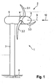
- FIG. 1 shows a schematic simplified perspective view of an inventive, diving power plant 1.
- This generically includes a water turbine, which is designed as an axial turbine 2.
- an axial turbine 2 with three turbine blades 3.1, 3.2, 3.3 is used, which are arranged along the peripheral surface of a hub 4 at an angular distance of 120 °.
- the axial turbine 2 runs together with the hood 6 on the nacelle housing.
- FIG. 1 apparent drive shaft in torsionally rigid connection to the axial turbine 2.
- the drive shaft transmits the driving torque at least indirectly to an electric generator (not shown).
- the nacelle housing 5 is fixed to a support structure 7, which is fundamental for the illustrated embodiment as a cylindrical tower on the body of water 8.
- a support structure 7 is used in a generalized manner and can also designate a buoyant unit with which the axial turbine 2 is at least indirectly connected.
- the support structure 7 is a flow obstacle and builds for a windward according to FIG. 1 in the upstream direction on a Turmvorstau. Each time the turbine blades pass through this tower prow, a pressure pulse is created.
- a corresponding problem exists for a Lee13r, here is the support structure with respect to the plane of rotation of the axial turbine 2 upstream, so that a tower shadow is created. In this case, the flow velocity falls locally in the tower shadow or the flow is otherwise influenced by the support structure 7; in the problematic case, an unsteady flow in the form of a vortex street arises.
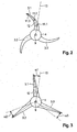
- the turbine blades 3.1, 3.2, 3.3 for an axial turbine 2 of a submersible power generation plant 1 according to the invention deviate along the longitudinal extension with respect to the projection into the plane of rotation from the radial direction.
- This is for two exemplary designs in the FIGS. 2 and 3 shown.
- the radial beam 13 is regarded as the radial leading to the direction of the axis of rotation 9 through the base point of the respective turbine blade.
- the turbine blades 3.1, 3.2, 3.3 for the projection on the plane of rotation a crescent-shaped course of Auffädelline 12.
- the Auffädelline 12 may have an additional directional component, which points in the normal direction to the plane of rotation of the axial turbine 2.
- the profile sections may be of any shape, in particular, the profiles of the three-digit Göttinger profile family come into consideration, wherein the profile profile of the turbine blades 3.1, 3.2, 3.3 can be configured as a wing profile. It is also conceivable to use a bidirectionally inflowable profile, in particular a point-symmetrical. In addition, the turbine blades, respectively their profile sections, occupy a predetermined angular position to the direction of flow 10. Furthermore, it is conceivable to form the turbine blades 3.1, 3.2, 3.3 rotationally rigidly connected to the hub or to associate them with an angle adjustment mechanism (pitch).
- an angle adjustment mechanism pitch
- FIG. 3 an embodiment of the invention is shown, for the course of a Auffädelline 12 of the turbine blades 3.1, 3.2, 3.3 in contrast to the embodiment according to FIG. 2 for the projection in the plane of rotation not sickle-shaped, but is straight-lined.
- the course of Auffädelline 12 has an angular deviation from the radial direction, which in FIG. 3 is illustrated for the respective turbine blades by the reference numerals ⁇ 1, ⁇ 2 and ⁇ 3.
- the angular deviations from the radial beam ⁇ 1, ⁇ 2, ⁇ 3 differ from one another, so that a symmetry operation is applied in the circumferential direction.
- the radially outer region of the turbine blades 3.1, 3.2, 3.3 is designed so that in the event of cavitation bubbles arising, they are guided over a reduced area of the turbine blades, so as to limit the damage potential.
- this is achieved by a curving or Abwirikeln the trailing edge of the rotor blades in the direction of rotation, d. H. the Auffädelline runs in the radially outer region of the radial beam ahead.
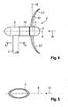
- the deviation of the course of the threading line 12 with respect to the radial direction may be a turbine blade from the plane of rotation 15 of the axial turbine 2 lead out.
- An example of such a design is in longitudinal section through a submersible power generation plant according to the invention FIG. 4 shown.
- a crescent-shaped course of the threading line can be seen in a plane which is predetermined by the radial direction 13 and the axis of rotation 9. Accordingly, the outer ends of the turbine blades 3.1, 3.2 jump forward or backward relative to the plane of rotation.
- the ends of the turbine blades 3.1, 3.2 upstream so that in particular the fast rotating parts of the turbine blades 3.1, 3.2, namely the turbine blade tips, a further distance in the direction of the axis of rotation of the axial turbine 2 of the support structure 7 than the near-hub areas. Consequently, the turbine blades 3.1, 3.2 traverse along their longitudinal extent at a predetermined time the area of the turret advance over a certain axial distance, wherein the turbine blade tip engages in a region of lesser influence by the support structure 7. As a result, the pressure pulses generated by the Turmvorstau can be further mitigated.
- elliptical or otherwise flattened cross sections in question so that the upstream nose of the Cross-section causes a low flow resistance and the Strömungsaustauf downstream is disturbed as low as possible.
Landscapes
- Engineering & Computer Science (AREA)
- Chemical & Material Sciences (AREA)
- Combustion & Propulsion (AREA)
- Mechanical Engineering (AREA)
- General Engineering & Computer Science (AREA)
- Power Engineering (AREA)
- Life Sciences & Earth Sciences (AREA)
- General Life Sciences & Earth Sciences (AREA)
- Oceanography (AREA)
- Other Liquid Machine Or Engine Such As Wave Power Use (AREA)
- Hydraulic Turbines (AREA)
Claims (9)
- Unité immergée de production d'énergie (1) entraînée par un courant de marée, comprenant1.1 une turbine à eau sous forme de turbine (2) avec des pales de turbine (3.1, 3.2, 3.3) et un axe de rotation associé (9), où la turbine axiale (2) est fixée à une structure d'appui (7) en forme de tour et où un plan de rotation (15) est associé à la turbine axiale (2), plan défini par l'axe de rotation (9) comme normale à la surface et un point de pied d'une pale de turbine (3.1, 3.2, 3.3);1.2 les pales de turbine (3.1, 3.2, 3.3) présentent un profil d'aile portante où les sections de profil (11.1. 11.2, 11.3) sont constituées le long d'une ligne d'empilage (12) dans une direction radiale vers l'extérieur avec une profondeur de profil réduisant de façon continue;
caractérisée en ce1.3 les pales de turbine (3.1, 3.2. 3.3) sont conçues de telle sorte que le tracé de la ligne d'empilage (12) des sections de profil respectifs (11.1, 11.2, 11.3), projeté sur le plan de rotation (15) de la turbine axiale (2), s'écarte du faisceau radial (13) et se projette de manière courbe sur un plan perpendiculaire au plan de rotation (15) pour que la ligne d'empilage (12) présente une composante de direction s'écartant de la structure d'appui (7). - Unité immergée de production d'énergie (1) selon la revendication 1, caractérisée en ce que les pales de turbine (3.1, 3.2, 3.3) sont affluables dans les deux directions.
- Unité immergée de production d'énergie (1) selon l'une des revendications 1 ou 2, caractérisée en ce que la projection de la ligne d'empilage (12) impacte le plan de rotation (15) de façon rectiligne et adopte un écart angulaire non nul (a1, a2, a3) par rapport au faisceau radial (13).
- Unité immergée de production d'énergie (1) selon l'une des revendications 1 ou 2, caractérisée en ce que la projection de la ligne d'empilage (12) impacte le plan de rotation (15) selon un tracé courbe.
- Unité immergée de production d'énergie (1) selon l'une quelconque au moins des revendications précédentes, caractérisée en ce que la zone des positions avant et arrière maximales de la projection de la ligne d'empilage (12) par rapport au faisceau radial présente un écart angulaire minimal d'au moins 10° par rapport au faisceau radial.
- Unité immergée de production d'énergie (1) selon l'une quelconque au moins des revendications précédentes, caractérisée en ce que la ligne d'empilage (12) présente une composante parallèle à l'axe de rotation (9) dans au moins une zone partielle.
- Unité immergée de production d'énergie (1) selon l'une quelconque au moins des revendications précédentes, comportant également une structure d'appui (7) asymétrique par rapport à l'axe de rotation (9) de la turbine axiale.
- Unité immergée de production d'énergie (1) selon l'une quelconque au moins des revendications précédentes, caractérisée en ce qu'un élément d'écartement axial (14) est prévu entre la structure d'appui (7) et la turbine à eau, élément écartant la turbine à eau de la structure d'appui (7) dans le sens de l'axe de rotation (9).
- Unité immergée de production d'énergie (1) selon l'une quelconque au moins des revendications précédentes, caractérisée en ce que la structure d'appui (7) est conçue en forme de ligne de courant pour réduire l'ombre de la tour et/ou les turbulences dues au passage des pales, au moins dans des zones partielles.
Applications Claiming Priority (2)
| Application Number | Priority Date | Filing Date | Title |
|---|---|---|---|
| DE102008007043A DE102008007043A1 (de) | 2008-01-31 | 2008-01-31 | Freistehende, tauchende Energieerzeugungsanlage mit einer Axialturbine |
| PCT/EP2009/000098 WO2009095149A2 (fr) | 2008-01-31 | 2009-01-10 | Installation de production d'énergie immergée indépendante munie d'une turbine axiale |
Publications (2)
| Publication Number | Publication Date |
|---|---|
| EP2242923A2 EP2242923A2 (fr) | 2010-10-27 |
| EP2242923B1 true EP2242923B1 (fr) | 2015-07-29 |
Family
ID=40822077
Family Applications (1)
| Application Number | Title | Priority Date | Filing Date |
|---|---|---|---|
| EP09706561.9A Not-in-force EP2242923B1 (fr) | 2008-01-31 | 2009-01-10 | Installation de production d'énergie immergée indépendante munie d'une turbine axiale |
Country Status (8)
| Country | Link |
|---|---|
| US (1) | US20110081251A1 (fr) |
| EP (1) | EP2242923B1 (fr) |
| KR (1) | KR20100115781A (fr) |
| CA (1) | CA2714289A1 (fr) |
| CL (1) | CL2009000159A1 (fr) |
| DE (1) | DE102008007043A1 (fr) |
| NZ (1) | NZ587411A (fr) |
| WO (1) | WO2009095149A2 (fr) |
Families Citing this family (7)
| Publication number | Priority date | Publication date | Assignee | Title |
|---|---|---|---|---|
| US8376686B2 (en) | 2007-03-23 | 2013-02-19 | Flodesign Wind Turbine Corp. | Water turbines with mixers and ejectors |
| CN102128128A (zh) * | 2011-03-23 | 2011-07-20 | 刘华栋 | 一种永磁直驱式潮流发电装置 |
| DE102011107286A1 (de) * | 2011-07-06 | 2013-01-10 | Voith Patent Gmbh | Strömungskraftwerk und Verfahren für dessen Betrieb |
| DE102011053370A1 (de) * | 2011-09-07 | 2013-03-07 | Schottel Gmbh | Wasserströmungskraftwerk |
| US8926289B2 (en) | 2012-03-08 | 2015-01-06 | Hamilton Sundstrand Corporation | Blade pocket design |
| JP6026786B2 (ja) * | 2012-06-08 | 2016-11-16 | 株式会社ベルシオン | 水力発電装置 |
| DE102012021689A1 (de) * | 2012-11-07 | 2014-01-09 | Voith Patent Gmbh | Strömungskraftwerk mit einer Wasserturbine und einem Generator |
Family Cites Families (28)
| Publication number | Priority date | Publication date | Assignee | Title |
|---|---|---|---|---|
| US1127143A (en) * | 1908-08-01 | 1915-02-02 | Wiedling Mfg Company | Propeller. |
| US970404A (en) * | 1909-07-28 | 1910-09-13 | American Power & Mfg Co | Fluid-actuated motor. |
| FR412148A (fr) * | 1910-01-13 | 1910-07-04 | William Snee | Moteurs du genre turbine |
| US1504737A (en) * | 1921-07-01 | 1924-08-12 | Allis Chalmers Mfg Co | Hydraulic turbine |
| US4219303A (en) * | 1977-10-27 | 1980-08-26 | Mouton William J Jr | Submarine turbine power plant |
| US4368007A (en) * | 1980-10-10 | 1983-01-11 | Ely Walter K | Fluid driven turbine |
| US4533297A (en) * | 1982-09-15 | 1985-08-06 | Bassett David A | Rotor system for horizontal axis wind turbines |
| US4613279A (en) * | 1984-03-22 | 1986-09-23 | Riverside Energy Technology, Inc. | Kinetic hydro energy conversion system |
| US5254876A (en) * | 1992-05-28 | 1993-10-19 | Hickey John J | Combined solar and wind powered generator with spiral blades |
| DK100497A (da) * | 1997-09-04 | 1997-09-04 | Novo Nordisk As | Kemisk forbindelse |
| ES2232959T3 (es) * | 1997-09-04 | 2005-06-01 | Lm Glasfiber A/S | Rotor de molino de viento y aspas para el mismo. |
| DE60014071T2 (de) * | 1999-02-24 | 2005-11-24 | Marine Current Turbines Ltd. | Um eine hülse angeordnete wasserströmungsturbine |
| DE19963252A1 (de) * | 1999-12-17 | 2001-07-12 | Lutz Schulze | Längsachsial verändertes Rotorblatt zur Erhöhung der Rotorleistung für HA-Windturbinen |
| JP4024208B2 (ja) * | 2001-09-17 | 2007-12-19 | クリーン カーレント パワー システムズ インコーポレイテッド | 水中用ダクテッドタービン |
| DE10212467A1 (de) * | 2002-03-20 | 2003-10-09 | Edzard Hafner | Windkraftanlage und deren Teile |
| NO320852B1 (no) | 2002-09-04 | 2006-02-06 | Hammerfest Strom As | Anordning med en skrastilt baeresoyle for forankring av en aksialturbin for produksjon av elektrisk energi fra vannstrommer |
| GB0229042D0 (en) * | 2002-12-13 | 2003-01-15 | Marine Current Turbines Ltd | Hydraulic speed-increasing transmission for water current powered turbine |
| JP2007529662A (ja) * | 2004-03-18 | 2007-10-25 | ロトリオンテ,フランク,ダニエル | タービンおよびそのためのローター |
| GB0408939D0 (en) * | 2004-04-22 | 2004-05-26 | Weir Strachan & Henshaw | Water current turbine |
| US7344360B2 (en) * | 2004-09-29 | 2008-03-18 | General Electric Company | Wind turbine rotor blade with in-plane sweep and devices using same, and methods for making same |
| GB0510417D0 (en) * | 2005-05-21 | 2005-06-29 | Rotech Holdings Ltd | Improved turbine |
| US7199484B2 (en) * | 2005-07-05 | 2007-04-03 | Gencor Industries Inc. | Water current generator |
| DE202005020071U1 (de) * | 2005-12-21 | 2006-06-29 | Grath, Christian | Wandler mit einer elektrischen Maschine sowie mehrstufiger Wandler |
| US20070205603A1 (en) * | 2006-03-03 | 2007-09-06 | Karl Appa | Methods and devices for improving efficiency of wind turbines in low wind speed sites |
| US20080018115A1 (en) * | 2006-07-20 | 2008-01-24 | Boray Technologies, Inc. | Semi-submersible hydroelectric power plant |
| US7789629B2 (en) * | 2006-12-07 | 2010-09-07 | Verdant Power | Non-fouling kinetic hydro power system axial-flow blade tip treatment |
| DE202007004170U1 (de) * | 2007-03-16 | 2007-06-14 | Schurig, Joachim | Energiegewinnungs-Sperrwerk in strömenden Gewässern |
| US8102071B2 (en) * | 2007-10-18 | 2012-01-24 | Catlin Christopher S | River and tidal power harvester |
-
2008
- 2008-01-31 DE DE102008007043A patent/DE102008007043A1/de not_active Withdrawn
-
2009
- 2009-01-10 EP EP09706561.9A patent/EP2242923B1/fr not_active Not-in-force
- 2009-01-10 NZ NZ587411A patent/NZ587411A/en unknown
- 2009-01-10 US US12/735,612 patent/US20110081251A1/en not_active Abandoned
- 2009-01-10 CA CA2714289A patent/CA2714289A1/fr not_active Abandoned
- 2009-01-10 WO PCT/EP2009/000098 patent/WO2009095149A2/fr not_active Ceased
- 2009-01-10 KR KR1020107019095A patent/KR20100115781A/ko not_active Ceased
- 2009-01-26 CL CL2009000159A patent/CL2009000159A1/es unknown
Also Published As
| Publication number | Publication date |
|---|---|
| WO2009095149A3 (fr) | 2010-04-08 |
| US20110081251A1 (en) | 2011-04-07 |
| KR20100115781A (ko) | 2010-10-28 |
| CL2009000159A1 (es) | 2010-11-12 |
| WO2009095149A2 (fr) | 2009-08-06 |
| EP2242923A2 (fr) | 2010-10-27 |
| NZ587411A (en) | 2011-12-22 |
| DE102008007043A1 (de) | 2009-08-06 |
| CA2714289A1 (fr) | 2009-08-06 |
Similar Documents
| Publication | Publication Date | Title |
|---|---|---|
| EP2242923B1 (fr) | Installation de production d'énergie immergée indépendante munie d'une turbine axiale | |
| EP2004990B1 (fr) | Pale de rotor d'un dispositif d'énergie éolienne | |
| DE60125172T2 (de) | Rotorblatt für eine windkraftanlage | |
| EP2594478B1 (fr) | Agencement à hélice, notamment pour bateaux | |
| WO1992005341A1 (fr) | Rotor | |
| DE102011118844B3 (de) | Vertikalwindturbine und Rotorblatt hierfür | |
| EP1196696A2 (fr) | Rotor dote d'une pale fendue | |
| WO2008141763A2 (fr) | Bras de support destiné aux pales de turbines éoliennes présentant un axe de rotation vertical | |
| WO2011113424A2 (fr) | Turbo machine comportant un réglage passif des aubes mobiles | |
| EP2339171A2 (fr) | Pale pour une éolienne | |
| WO2009098007A2 (fr) | Configuration d'une aube de rotor pour une turbine wells | |
| DE202016101461U1 (de) | Rotorblatt für Windenergieanlagen mit horizontaler Drehachse sowieWindenergieanlage mit selbigem | |
| DE102013206437A1 (de) | Rotorblatt einer Windenergieanlage und Windenergieanlage | |
| EP2985452A1 (fr) | Corps de rallonge de pale de rotor et eolienne | |
| EP3147499B1 (fr) | Pale de rotor a profil optimise contre le bruit et procede de fabrication d'une pale de rotor | |
| EP3066337A1 (fr) | Pale de rotor d'une éolienne et éolienne | |
| DE102004029109A1 (de) | Francisturbine | |
| EP3399183B1 (fr) | Pale de rotor d'une éolienne | |
| EP1211414A2 (fr) | Turbine | |
| DE102011052667A1 (de) | Schwimmkraftwerk | |
| DE202004018879U1 (de) | Wind- und Wasserkraftanlage mit Vertikalrotoren | |
| EP2920454B1 (fr) | Dispositif pour exploiter l'énergie cinétique d'un fluide en écoulement | |
| DE102009018924A1 (de) | Bidirektional anströmbare Turbine | |
| DE102019113848A1 (de) | Turbinenvorrichtung | |
| AT527653B1 (de) | Vorrichtung zur Gewinnung elektrischer Energie aus Strömungsenergie eines strömenden Gewässers |
Legal Events
| Date | Code | Title | Description |
|---|---|---|---|
| PUAI | Public reference made under article 153(3) epc to a published international application that has entered the european phase |
Free format text: ORIGINAL CODE: 0009012 |
|
| 17P | Request for examination filed |
Effective date: 20100811 |
|
| AK | Designated contracting states |
Kind code of ref document: A2 Designated state(s): AT BE BG CH CY CZ DE DK EE ES FI FR GB GR HR HU IE IS IT LI LT LU LV MC MK MT NL NO PL PT RO SE SI SK TR |
|
| AX | Request for extension of the european patent |
Extension state: AL BA RS |
|
| DAX | Request for extension of the european patent (deleted) | ||
| GRAP | Despatch of communication of intention to grant a patent |
Free format text: ORIGINAL CODE: EPIDOSNIGR1 |
|
| INTG | Intention to grant announced |
Effective date: 20150417 |
|
| GRAS | Grant fee paid |
Free format text: ORIGINAL CODE: EPIDOSNIGR3 |
|
| GRAA | (expected) grant |
Free format text: ORIGINAL CODE: 0009210 |
|
| AK | Designated contracting states |
Kind code of ref document: B1 Designated state(s): AT BE BG CH CY CZ DE DK EE ES FI FR GB GR HR HU IE IS IT LI LT LU LV MC MK MT NL NO PL PT RO SE SI SK TR |
|
| REG | Reference to a national code |
Ref country code: GB Ref legal event code: FG4D Free format text: NOT ENGLISH |
|
| REG | Reference to a national code |
Ref country code: CH Ref legal event code: EP |
|
| REG | Reference to a national code |
Ref country code: AT Ref legal event code: REF Ref document number: 739512 Country of ref document: AT Kind code of ref document: T Effective date: 20150815 |
|
| REG | Reference to a national code |
Ref country code: IE Ref legal event code: FG4D Free format text: LANGUAGE OF EP DOCUMENT: GERMAN |
|
| REG | Reference to a national code |
Ref country code: DE Ref legal event code: R096 Ref document number: 502009011322 Country of ref document: DE |
|
| REG | Reference to a national code |
Ref country code: LT Ref legal event code: MG4D |
|
| REG | Reference to a national code |
Ref country code: NL Ref legal event code: MP Effective date: 20150729 |
|
| REG | Reference to a national code |
Ref country code: FR Ref legal event code: PLFP Year of fee payment: 8 |
|
| PG25 | Lapsed in a contracting state [announced via postgrant information from national office to epo] |
Ref country code: LV Free format text: LAPSE BECAUSE OF FAILURE TO SUBMIT A TRANSLATION OF THE DESCRIPTION OR TO PAY THE FEE WITHIN THE PRESCRIBED TIME-LIMIT Effective date: 20150729 Ref country code: GR Free format text: LAPSE BECAUSE OF FAILURE TO SUBMIT A TRANSLATION OF THE DESCRIPTION OR TO PAY THE FEE WITHIN THE PRESCRIBED TIME-LIMIT Effective date: 20151030 Ref country code: FI Free format text: LAPSE BECAUSE OF FAILURE TO SUBMIT A TRANSLATION OF THE DESCRIPTION OR TO PAY THE FEE WITHIN THE PRESCRIBED TIME-LIMIT Effective date: 20150729 Ref country code: NO Free format text: LAPSE BECAUSE OF FAILURE TO SUBMIT A TRANSLATION OF THE DESCRIPTION OR TO PAY THE FEE WITHIN THE PRESCRIBED TIME-LIMIT Effective date: 20151029 Ref country code: LT Free format text: LAPSE BECAUSE OF FAILURE TO SUBMIT A TRANSLATION OF THE DESCRIPTION OR TO PAY THE FEE WITHIN THE PRESCRIBED TIME-LIMIT Effective date: 20150729 |
|
| PG25 | Lapsed in a contracting state [announced via postgrant information from national office to epo] |
Ref country code: ES Free format text: LAPSE BECAUSE OF FAILURE TO SUBMIT A TRANSLATION OF THE DESCRIPTION OR TO PAY THE FEE WITHIN THE PRESCRIBED TIME-LIMIT Effective date: 20150729 Ref country code: PL Free format text: LAPSE BECAUSE OF FAILURE TO SUBMIT A TRANSLATION OF THE DESCRIPTION OR TO PAY THE FEE WITHIN THE PRESCRIBED TIME-LIMIT Effective date: 20150729 Ref country code: SE Free format text: LAPSE BECAUSE OF FAILURE TO SUBMIT A TRANSLATION OF THE DESCRIPTION OR TO PAY THE FEE WITHIN THE PRESCRIBED TIME-LIMIT Effective date: 20150729 Ref country code: HR Free format text: LAPSE BECAUSE OF FAILURE TO SUBMIT A TRANSLATION OF THE DESCRIPTION OR TO PAY THE FEE WITHIN THE PRESCRIBED TIME-LIMIT Effective date: 20150729 Ref country code: IS Free format text: LAPSE BECAUSE OF FAILURE TO SUBMIT A TRANSLATION OF THE DESCRIPTION OR TO PAY THE FEE WITHIN THE PRESCRIBED TIME-LIMIT Effective date: 20151129 Ref country code: PT Free format text: LAPSE BECAUSE OF FAILURE TO SUBMIT A TRANSLATION OF THE DESCRIPTION OR TO PAY THE FEE WITHIN THE PRESCRIBED TIME-LIMIT Effective date: 20151130 |
|
| PG25 | Lapsed in a contracting state [announced via postgrant information from national office to epo] |
Ref country code: NL Free format text: LAPSE BECAUSE OF FAILURE TO SUBMIT A TRANSLATION OF THE DESCRIPTION OR TO PAY THE FEE WITHIN THE PRESCRIBED TIME-LIMIT Effective date: 20150729 |
|
| PG25 | Lapsed in a contracting state [announced via postgrant information from national office to epo] |
Ref country code: SK Free format text: LAPSE BECAUSE OF FAILURE TO SUBMIT A TRANSLATION OF THE DESCRIPTION OR TO PAY THE FEE WITHIN THE PRESCRIBED TIME-LIMIT Effective date: 20150729 Ref country code: DK Free format text: LAPSE BECAUSE OF FAILURE TO SUBMIT A TRANSLATION OF THE DESCRIPTION OR TO PAY THE FEE WITHIN THE PRESCRIBED TIME-LIMIT Effective date: 20150729 Ref country code: EE Free format text: LAPSE BECAUSE OF FAILURE TO SUBMIT A TRANSLATION OF THE DESCRIPTION OR TO PAY THE FEE WITHIN THE PRESCRIBED TIME-LIMIT Effective date: 20150729 Ref country code: IT Free format text: LAPSE BECAUSE OF FAILURE TO SUBMIT A TRANSLATION OF THE DESCRIPTION OR TO PAY THE FEE WITHIN THE PRESCRIBED TIME-LIMIT Effective date: 20150729 Ref country code: CZ Free format text: LAPSE BECAUSE OF FAILURE TO SUBMIT A TRANSLATION OF THE DESCRIPTION OR TO PAY THE FEE WITHIN THE PRESCRIBED TIME-LIMIT Effective date: 20150729 |
|
| REG | Reference to a national code |
Ref country code: DE Ref legal event code: R097 Ref document number: 502009011322 Country of ref document: DE |
|
| PG25 | Lapsed in a contracting state [announced via postgrant information from national office to epo] |
Ref country code: RO Free format text: LAPSE BECAUSE OF FAILURE TO SUBMIT A TRANSLATION OF THE DESCRIPTION OR TO PAY THE FEE WITHIN THE PRESCRIBED TIME-LIMIT Effective date: 20150729 Ref country code: BE Free format text: LAPSE BECAUSE OF NON-PAYMENT OF DUE FEES Effective date: 20160131 |
|
| PLBE | No opposition filed within time limit |
Free format text: ORIGINAL CODE: 0009261 |
|
| STAA | Information on the status of an ep patent application or granted ep patent |
Free format text: STATUS: NO OPPOSITION FILED WITHIN TIME LIMIT |
|
| 26N | No opposition filed |
Effective date: 20160502 |
|
| PG25 | Lapsed in a contracting state [announced via postgrant information from national office to epo] |
Ref country code: LU Free format text: LAPSE BECAUSE OF FAILURE TO SUBMIT A TRANSLATION OF THE DESCRIPTION OR TO PAY THE FEE WITHIN THE PRESCRIBED TIME-LIMIT Effective date: 20160110 Ref country code: SI Free format text: LAPSE BECAUSE OF FAILURE TO SUBMIT A TRANSLATION OF THE DESCRIPTION OR TO PAY THE FEE WITHIN THE PRESCRIBED TIME-LIMIT Effective date: 20150729 |
|
| REG | Reference to a national code |
Ref country code: CH Ref legal event code: PL |
|
| PG25 | Lapsed in a contracting state [announced via postgrant information from national office to epo] |
Ref country code: MC Free format text: LAPSE BECAUSE OF FAILURE TO SUBMIT A TRANSLATION OF THE DESCRIPTION OR TO PAY THE FEE WITHIN THE PRESCRIBED TIME-LIMIT Effective date: 20150729 |
|
| PG25 | Lapsed in a contracting state [announced via postgrant information from national office to epo] |
Ref country code: LI Free format text: LAPSE BECAUSE OF NON-PAYMENT OF DUE FEES Effective date: 20160131 Ref country code: CH Free format text: LAPSE BECAUSE OF NON-PAYMENT OF DUE FEES Effective date: 20160131 |
|
| REG | Reference to a national code |
Ref country code: IE Ref legal event code: MM4A |
|
| REG | Reference to a national code |
Ref country code: FR Ref legal event code: PLFP Year of fee payment: 9 |
|
| PG25 | Lapsed in a contracting state [announced via postgrant information from national office to epo] |
Ref country code: IE Free format text: LAPSE BECAUSE OF NON-PAYMENT OF DUE FEES Effective date: 20160110 |
|
| REG | Reference to a national code |
Ref country code: AT Ref legal event code: MM01 Ref document number: 739512 Country of ref document: AT Kind code of ref document: T Effective date: 20160110 |
|
| PG25 | Lapsed in a contracting state [announced via postgrant information from national office to epo] |
Ref country code: AT Free format text: LAPSE BECAUSE OF NON-PAYMENT OF DUE FEES Effective date: 20160110 |
|
| PG25 | Lapsed in a contracting state [announced via postgrant information from national office to epo] |
Ref country code: MT Free format text: LAPSE BECAUSE OF FAILURE TO SUBMIT A TRANSLATION OF THE DESCRIPTION OR TO PAY THE FEE WITHIN THE PRESCRIBED TIME-LIMIT Effective date: 20150729 |
|
| REG | Reference to a national code |
Ref country code: FR Ref legal event code: PLFP Year of fee payment: 10 |
|
| PG25 | Lapsed in a contracting state [announced via postgrant information from national office to epo] |
Ref country code: CY Free format text: LAPSE BECAUSE OF FAILURE TO SUBMIT A TRANSLATION OF THE DESCRIPTION OR TO PAY THE FEE WITHIN THE PRESCRIBED TIME-LIMIT Effective date: 20150729 Ref country code: HU Free format text: LAPSE BECAUSE OF FAILURE TO SUBMIT A TRANSLATION OF THE DESCRIPTION OR TO PAY THE FEE WITHIN THE PRESCRIBED TIME-LIMIT; INVALID AB INITIO Effective date: 20090110 |
|
| PG25 | Lapsed in a contracting state [announced via postgrant information from national office to epo] |
Ref country code: MK Free format text: LAPSE BECAUSE OF FAILURE TO SUBMIT A TRANSLATION OF THE DESCRIPTION OR TO PAY THE FEE WITHIN THE PRESCRIBED TIME-LIMIT Effective date: 20150729 Ref country code: TR Free format text: LAPSE BECAUSE OF FAILURE TO SUBMIT A TRANSLATION OF THE DESCRIPTION OR TO PAY THE FEE WITHIN THE PRESCRIBED TIME-LIMIT Effective date: 20150729 |
|
| PG25 | Lapsed in a contracting state [announced via postgrant information from national office to epo] |
Ref country code: BG Free format text: LAPSE BECAUSE OF FAILURE TO SUBMIT A TRANSLATION OF THE DESCRIPTION OR TO PAY THE FEE WITHIN THE PRESCRIBED TIME-LIMIT Effective date: 20150729 |
|
| PGFP | Annual fee paid to national office [announced via postgrant information from national office to epo] |
Ref country code: DE Payment date: 20200121 Year of fee payment: 12 Ref country code: GB Payment date: 20200124 Year of fee payment: 12 |
|
| PGFP | Annual fee paid to national office [announced via postgrant information from national office to epo] |
Ref country code: FR Payment date: 20200121 Year of fee payment: 12 |
|
| REG | Reference to a national code |
Ref country code: DE Ref legal event code: R119 Ref document number: 502009011322 Country of ref document: DE |
|
| GBPC | Gb: european patent ceased through non-payment of renewal fee |
Effective date: 20210110 |
|
| PG25 | Lapsed in a contracting state [announced via postgrant information from national office to epo] |
Ref country code: FR Free format text: LAPSE BECAUSE OF NON-PAYMENT OF DUE FEES Effective date: 20210131 |
|
| PG25 | Lapsed in a contracting state [announced via postgrant information from national office to epo] |
Ref country code: DE Free format text: LAPSE BECAUSE OF NON-PAYMENT OF DUE FEES Effective date: 20210803 Ref country code: GB Free format text: LAPSE BECAUSE OF NON-PAYMENT OF DUE FEES Effective date: 20210110 |