EP2243426A1 - Lanzettenvorrichtung und einstichvorrichtung - Google Patents
Lanzettenvorrichtung und einstichvorrichtung Download PDFInfo
- Publication number
- EP2243426A1 EP2243426A1 EP08862071A EP08862071A EP2243426A1 EP 2243426 A1 EP2243426 A1 EP 2243426A1 EP 08862071 A EP08862071 A EP 08862071A EP 08862071 A EP08862071 A EP 08862071A EP 2243426 A1 EP2243426 A1 EP 2243426A1
- Authority
- EP
- European Patent Office
- Prior art keywords
- lancet
- puncture
- piercing
- movable
- casing
- Prior art date
- Legal status (The legal status is an assumption and is not a legal conclusion. Google has not performed a legal analysis and makes no representation as to the accuracy of the status listed.)
- Withdrawn
Links
- 230000007246 mechanism Effects 0.000 claims description 32
- 230000000717 retained effect Effects 0.000 claims description 17
- 239000000470 constituent Substances 0.000 claims description 14
- 230000001105 regulatory effect Effects 0.000 claims description 7
- 239000012530 fluid Substances 0.000 claims description 6
- 238000003780 insertion Methods 0.000 claims description 4
- 230000037431 insertion Effects 0.000 claims description 4
- 239000008280 blood Substances 0.000 description 50
- 210000004369 blood Anatomy 0.000 description 50
- 238000005259 measurement Methods 0.000 description 6
- 230000004044 response Effects 0.000 description 6
- 238000004519 manufacturing process Methods 0.000 description 4
- 208000019901 Anxiety disease Diseases 0.000 description 3
- 108090000854 Oxidoreductases Proteins 0.000 description 3
- 102000004316 Oxidoreductases Human genes 0.000 description 3
- 230000036506 anxiety Effects 0.000 description 3
- 238000000034 method Methods 0.000 description 3
- 230000000452 restraining effect Effects 0.000 description 3
- 239000000126 substance Substances 0.000 description 3
- 239000000758 substrate Substances 0.000 description 3
- WQZGKKKJIJFFOK-GASJEMHNSA-N Glucose Natural products OC[C@H]1OC(O)[C@H](O)[C@@H](O)[C@@H]1O WQZGKKKJIJFFOK-GASJEMHNSA-N 0.000 description 2
- 108010050375 Glucose 1-Dehydrogenase Proteins 0.000 description 2
- 108010015776 Glucose oxidase Proteins 0.000 description 2
- 239000004366 Glucose oxidase Substances 0.000 description 2
- 239000003153 chemical reaction reagent Substances 0.000 description 2
- HVYWMOMLDIMFJA-DPAQBDIFSA-N cholesterol Chemical compound C1C=C2C[C@@H](O)CC[C@]2(C)[C@@H]2[C@@H]1[C@@H]1CC[C@H]([C@H](C)CCCC(C)C)[C@@]1(C)CC2 HVYWMOMLDIMFJA-DPAQBDIFSA-N 0.000 description 2
- 239000008103 glucose Substances 0.000 description 2
- 235000019420 glucose oxidase Nutrition 0.000 description 2
- 229940116332 glucose oxidase Drugs 0.000 description 2
- JVTAAEKCZFNVCJ-UHFFFAOYSA-N lactic acid Chemical compound CC(O)C(O)=O JVTAAEKCZFNVCJ-UHFFFAOYSA-N 0.000 description 2
- 238000000465 moulding Methods 0.000 description 2
- 238000003825 pressing Methods 0.000 description 2
- 239000011347 resin Substances 0.000 description 2
- 229920005989 resin Polymers 0.000 description 2
- 125000006850 spacer group Chemical group 0.000 description 2
- 239000012327 Ruthenium complex Substances 0.000 description 1
- 230000017531 blood circulation Effects 0.000 description 1
- 230000008859 change Effects 0.000 description 1
- 235000012000 cholesterol Nutrition 0.000 description 1
- 210000003722 extracellular fluid Anatomy 0.000 description 1
- 230000004438 eyesight Effects 0.000 description 1
- 230000006872 improvement Effects 0.000 description 1
- 230000002452 interceptive effect Effects 0.000 description 1
- XEEYBQQBJWHFJM-UHFFFAOYSA-N iron Substances [Fe] XEEYBQQBJWHFJM-UHFFFAOYSA-N 0.000 description 1
- 150000004698 iron complex Chemical class 0.000 description 1
- 235000014655 lactic acid Nutrition 0.000 description 1
- 239000004310 lactic acid Substances 0.000 description 1
- 230000008569 process Effects 0.000 description 1
- 230000009467 reduction Effects 0.000 description 1
- 230000001954 sterilising effect Effects 0.000 description 1
Images









Classifications
-
- A—HUMAN NECESSITIES
- A61—MEDICAL OR VETERINARY SCIENCE; HYGIENE
- A61B—DIAGNOSIS; SURGERY; IDENTIFICATION
- A61B5/00—Measuring for diagnostic purposes; Identification of persons
- A61B5/145—Measuring characteristics of blood in vivo, e.g. gas concentration or pH-value ; Measuring characteristics of body fluids or tissues, e.g. interstitial fluid or cerebral tissue
- A61B5/14532—Measuring characteristics of blood in vivo, e.g. gas concentration or pH-value ; Measuring characteristics of body fluids or tissues, e.g. interstitial fluid or cerebral tissue for measuring glucose, e.g. by tissue impedance measurement
-
- A—HUMAN NECESSITIES
- A61—MEDICAL OR VETERINARY SCIENCE; HYGIENE
- A61B—DIAGNOSIS; SURGERY; IDENTIFICATION
- A61B5/00—Measuring for diagnostic purposes; Identification of persons
- A61B5/145—Measuring characteristics of blood in vivo, e.g. gas concentration or pH-value ; Measuring characteristics of body fluids or tissues, e.g. interstitial fluid or cerebral tissue
- A61B5/14546—Measuring characteristics of blood in vivo, e.g. gas concentration or pH-value ; Measuring characteristics of body fluids or tissues, e.g. interstitial fluid or cerebral tissue for measuring analytes not otherwise provided for, e.g. ions, cytochromes
-
- A—HUMAN NECESSITIES
- A61—MEDICAL OR VETERINARY SCIENCE; HYGIENE
- A61B—DIAGNOSIS; SURGERY; IDENTIFICATION
- A61B5/00—Measuring for diagnostic purposes; Identification of persons
- A61B5/145—Measuring characteristics of blood in vivo, e.g. gas concentration or pH-value ; Measuring characteristics of body fluids or tissues, e.g. interstitial fluid or cerebral tissue
- A61B5/1468—Measuring characteristics of blood in vivo, e.g. gas concentration or pH-value ; Measuring characteristics of body fluids or tissues, e.g. interstitial fluid or cerebral tissue using chemical or electrochemical methods, e.g. by polarographic means
- A61B5/1486—Measuring characteristics of blood in vivo, e.g. gas concentration or pH-value ; Measuring characteristics of body fluids or tissues, e.g. interstitial fluid or cerebral tissue using chemical or electrochemical methods, e.g. by polarographic means using enzyme electrodes, e.g. with immobilised oxidase
-
- A—HUMAN NECESSITIES
- A61—MEDICAL OR VETERINARY SCIENCE; HYGIENE
- A61B—DIAGNOSIS; SURGERY; IDENTIFICATION
- A61B5/00—Measuring for diagnostic purposes; Identification of persons
- A61B5/15—Devices for taking samples of blood
- A61B5/150007—Details
- A61B5/150015—Source of blood
- A61B5/150022—Source of blood for capillary blood or interstitial fluid
-
- A—HUMAN NECESSITIES
- A61—MEDICAL OR VETERINARY SCIENCE; HYGIENE
- A61B—DIAGNOSIS; SURGERY; IDENTIFICATION
- A61B5/00—Measuring for diagnostic purposes; Identification of persons
- A61B5/15—Devices for taking samples of blood
- A61B5/150007—Details
- A61B5/150206—Construction or design features not otherwise provided for; manufacturing or production; packages; sterilisation of piercing element, piercing device or sampling device
- A61B5/150213—Venting means
-
- A—HUMAN NECESSITIES
- A61—MEDICAL OR VETERINARY SCIENCE; HYGIENE
- A61B—DIAGNOSIS; SURGERY; IDENTIFICATION
- A61B5/00—Measuring for diagnostic purposes; Identification of persons
- A61B5/15—Devices for taking samples of blood
- A61B5/150007—Details
- A61B5/150358—Strips for collecting blood, e.g. absorbent
-
- A—HUMAN NECESSITIES
- A61—MEDICAL OR VETERINARY SCIENCE; HYGIENE
- A61B—DIAGNOSIS; SURGERY; IDENTIFICATION
- A61B5/00—Measuring for diagnostic purposes; Identification of persons
- A61B5/15—Devices for taking samples of blood
- A61B5/150007—Details
- A61B5/150374—Details of piercing elements or protective means for preventing accidental injuries by such piercing elements
- A61B5/150381—Design of piercing elements
- A61B5/150412—Pointed piercing elements, e.g. needles, lancets for piercing the skin
-
- A—HUMAN NECESSITIES
- A61—MEDICAL OR VETERINARY SCIENCE; HYGIENE
- A61B—DIAGNOSIS; SURGERY; IDENTIFICATION
- A61B5/00—Measuring for diagnostic purposes; Identification of persons
- A61B5/15—Devices for taking samples of blood
- A61B5/150007—Details
- A61B5/150374—Details of piercing elements or protective means for preventing accidental injuries by such piercing elements
- A61B5/150381—Design of piercing elements
- A61B5/150503—Single-ended needles
- A61B5/150519—Details of construction of hub, i.e. element used to attach the single-ended needle to a piercing device or sampling device
-
- A—HUMAN NECESSITIES
- A61—MEDICAL OR VETERINARY SCIENCE; HYGIENE
- A61B—DIAGNOSIS; SURGERY; IDENTIFICATION
- A61B5/00—Measuring for diagnostic purposes; Identification of persons
- A61B5/15—Devices for taking samples of blood
- A61B5/150007—Details
- A61B5/150374—Details of piercing elements or protective means for preventing accidental injuries by such piercing elements
- A61B5/150534—Design of protective means for piercing elements for preventing accidental needle sticks, e.g. shields, caps, protectors, axially extensible sleeves, pivotable protective sleeves
- A61B5/150541—Breakable protectors, e.g. caps, shields or sleeves, i.e. protectors separated destructively, e.g. by breaking a connecting area
- A61B5/150549—Protectors removed by rotational movement, e.g. torsion or screwing
-
- A—HUMAN NECESSITIES
- A61—MEDICAL OR VETERINARY SCIENCE; HYGIENE
- A61B—DIAGNOSIS; SURGERY; IDENTIFICATION
- A61B5/00—Measuring for diagnostic purposes; Identification of persons
- A61B5/15—Devices for taking samples of blood
- A61B5/150007—Details
- A61B5/150374—Details of piercing elements or protective means for preventing accidental injuries by such piercing elements
- A61B5/150534—Design of protective means for piercing elements for preventing accidental needle sticks, e.g. shields, caps, protectors, axially extensible sleeves, pivotable protective sleeves
- A61B5/15058—Joining techniques used for protective means
- A61B5/150618—Integrally moulded protectors, e.g. protectors simultaneously moulded together with a further component, e.g. a hub, of the piercing element
-
- A—HUMAN NECESSITIES
- A61—MEDICAL OR VETERINARY SCIENCE; HYGIENE
- A61B—DIAGNOSIS; SURGERY; IDENTIFICATION
- A61B5/00—Measuring for diagnostic purposes; Identification of persons
- A61B5/15—Devices for taking samples of blood
- A61B5/150007—Details
- A61B5/150374—Details of piercing elements or protective means for preventing accidental injuries by such piercing elements
- A61B5/150534—Design of protective means for piercing elements for preventing accidental needle sticks, e.g. shields, caps, protectors, axially extensible sleeves, pivotable protective sleeves
- A61B5/150694—Procedure for removing protection means at the time of piercing
- A61B5/150717—Procedure for removing protection means at the time of piercing manually removed
-
- A—HUMAN NECESSITIES
- A61—MEDICAL OR VETERINARY SCIENCE; HYGIENE
- A61B—DIAGNOSIS; SURGERY; IDENTIFICATION
- A61B5/00—Measuring for diagnostic purposes; Identification of persons
- A61B5/15—Devices for taking samples of blood
- A61B5/151—Devices specially adapted for taking samples of capillary blood, e.g. by lancets, needles or blades
- A61B5/15101—Details
- A61B5/15103—Piercing procedure
- A61B5/15107—Piercing being assisted by a triggering mechanism
- A61B5/15113—Manually triggered, i.e. the triggering requires a deliberate action by the user such as pressing a drive button
-
- A—HUMAN NECESSITIES
- A61—MEDICAL OR VETERINARY SCIENCE; HYGIENE
- A61B—DIAGNOSIS; SURGERY; IDENTIFICATION
- A61B5/00—Measuring for diagnostic purposes; Identification of persons
- A61B5/15—Devices for taking samples of blood
- A61B5/151—Devices specially adapted for taking samples of capillary blood, e.g. by lancets, needles or blades
- A61B5/15101—Details
- A61B5/15115—Driving means for propelling the piercing element to pierce the skin, e.g. comprising mechanisms based on shape memory alloys, magnetism, solenoids, piezoelectric effect, biased elements, resilient elements, vacuum or compressed fluids
- A61B5/15117—Driving means for propelling the piercing element to pierce the skin, e.g. comprising mechanisms based on shape memory alloys, magnetism, solenoids, piezoelectric effect, biased elements, resilient elements, vacuum or compressed fluids comprising biased elements, resilient elements or a spring, e.g. a helical spring, leaf spring, or elastic strap
-
- A—HUMAN NECESSITIES
- A61—MEDICAL OR VETERINARY SCIENCE; HYGIENE
- A61B—DIAGNOSIS; SURGERY; IDENTIFICATION
- A61B5/00—Measuring for diagnostic purposes; Identification of persons
- A61B5/15—Devices for taking samples of blood
- A61B5/151—Devices specially adapted for taking samples of capillary blood, e.g. by lancets, needles or blades
- A61B5/15101—Details
- A61B5/15126—Means for controlling the lancing movement, e.g. 2D- or 3D-shaped elements, tooth-shaped elements or sliding guides
- A61B5/15128—Means for controlling the lancing movement, e.g. 2D- or 3D-shaped elements, tooth-shaped elements or sliding guides comprising 2D- or 3D-shaped elements, e.g. cams, curved guide rails or threads
-
- A—HUMAN NECESSITIES
- A61—MEDICAL OR VETERINARY SCIENCE; HYGIENE
- A61B—DIAGNOSIS; SURGERY; IDENTIFICATION
- A61B5/00—Measuring for diagnostic purposes; Identification of persons
- A61B5/15—Devices for taking samples of blood
- A61B5/151—Devices specially adapted for taking samples of capillary blood, e.g. by lancets, needles or blades
- A61B5/15186—Devices loaded with a single lancet, i.e. a single lancet with or without a casing is loaded into a reusable drive device and then discarded after use; drive devices reloadable for multiple use
- A61B5/15188—Constructional features of reusable driving devices
- A61B5/1519—Constructional features of reusable driving devices comprising driving means, e.g. a spring, for propelling the piercing unit
-
- A—HUMAN NECESSITIES
- A61—MEDICAL OR VETERINARY SCIENCE; HYGIENE
- A61B—DIAGNOSIS; SURGERY; IDENTIFICATION
- A61B5/00—Measuring for diagnostic purposes; Identification of persons
- A61B5/15—Devices for taking samples of blood
- A61B5/151—Devices specially adapted for taking samples of capillary blood, e.g. by lancets, needles or blades
- A61B5/15186—Devices loaded with a single lancet, i.e. a single lancet with or without a casing is loaded into a reusable drive device and then discarded after use; drive devices reloadable for multiple use
- A61B5/15188—Constructional features of reusable driving devices
- A61B5/15192—Constructional features of reusable driving devices comprising driving means, e.g. a spring, for retracting the lancet unit into the driving device housing
- A61B5/15194—Constructional features of reusable driving devices comprising driving means, e.g. a spring, for retracting the lancet unit into the driving device housing fully automatically retracted, i.e. the retraction does not require a deliberate action by the user, e.g. by terminating the contact with the patient's skin
-
- A—HUMAN NECESSITIES
- A61—MEDICAL OR VETERINARY SCIENCE; HYGIENE
- A61B—DIAGNOSIS; SURGERY; IDENTIFICATION
- A61B5/00—Measuring for diagnostic purposes; Identification of persons
- A61B5/15—Devices for taking samples of blood
- A61B5/157—Devices characterised by integrated means for measuring characteristics of blood
Definitions
- the present invention relates to a lancet device and a puncture device used when, for example, a specimen, such as a blood or an interstitial fluid, is extracted through a skin.
- the skin is pierced using a puncture device to which, for example, a lancet is attached.
- the blood is supplied to the analytical instrument by, for example, contacting a specimen inlet of the analytical instrument with a blood flow-out site of the skin.
- the blood is supplied to the analytical instrument before the analytical instrument is attached to a blood analyzer, or with the analytical instrument being attached to the blood analyzer.
- a puncture device which can be united with a blood analyzer (see, for example, Patent Literatures 1 and 2).
- the blood analyzer and the puncture device can be used in a united condition, or can be used individually, which results in improvement of the usability.
- attachment of a lancet or an analytical instrument and contacting of the analytical instrument with a blood flow-out site appropriately are not still improved, which leaves botheration and difficulty.
- Such device can pierce a skin with a lancet and can supply a specimen to an analytical instrument by merely being attached to an analyzer and being used as it is.
- the integrated-type device in general, as the lancet is retained in a casing, it is difficult for a user to check the lancet or a flow-out condition of a blood through a skin when the skin is pierced. As a result, insufficient supply of a specimen to the analytical instrument or measurement error is likely to happen originating from the user's anxiety when the skin is pierced, or difficulty of checking of a blood flow-out condition through the skin.
- the present invention according to a first aspect provides a lancet device which is attached to a puncture device and is used for piercing a target site, and which retains a lancet comprising a puncture needle in an internal space of a casing, wherein the casing includes a visible region through which a leading end of the lancet is visually recognizable.
- the casing comprises, for example, a main body including the internal space, and a cover which covers a part of the internal space.
- the visible region is not covered by the cover in the internal space, and includes an opened part adjacent to the cover.
- the visible region should make the puncture needle visually recognizable.
- the main body includes, for example, a wall which defines the internal space. It is preferable that the wall should include a recess which allows the puncture needle of the lancet to move, and configures a part of the visible region.
- the lancet comprises, for example, a lancet main body including the puncture needle and an engaging part, and a cap which covers a leading end of the puncture needle and is detachable from the lancet main body.
- the casing should comprise a first stopper and a second stopper which restrain the engaging part, and substantially restrict a movement of the lancet in the internal space.
- the casing may comprise a stopper for regulating an insertion depth to the puncture device when attached to the puncture device.
- the lancet device of the present invention may further comprise an analytical instrument retained in the casing.
- the casing should comprise a flow path for supplying a fluid flowing out from the target site to the analytical instrument.
- the flow path extends along, for example, a moving route of the puncture needle, and includes a suction part to be contacted with the target site. Moreover, the flow path may further include a through-hole opened in a retaining face on which the analytical instrument is held.
- the present invention according to a second aspect provides a puncture device to which a lancet device is attached and which is for piercing a target site, wherein the puncture device employs the lancet device according to the first aspect of the present invention as the lancet device.
- the puncture device may further comprise an analyzing mechanism which analyzes a specific constituent in the fluid using the analytical instrument.
- the present invention according to a third aspect provides a puncture device for moving a puncture element in a piercing direction from a stand-by position toward a piercing position, and for piercing a target site with the puncture element
- the puncture device comprises a first member which is movable in the piercing direction and in an evacuating direction opposite to the piercing direction, a second member which is movable in the piercing direction and in the evacuating direction together with a motion of the first member, and a third member which is movable together with the puncture element and the second member, and is movable in the piercing direction and in the evacuating direction.
- the puncture device should further comprise a fourth member for interconnecting the first member and the second member together, and for converting a motion of the first member into a reciprocating motion of the second member.
- the fourth member comprises, for example, a rotating shaft fixed at a certain position, a first movable part which engages with the first member, and is rotatable around the rotating shaft, and a second movable part which engages with the second member, and is rotatable around the rotating shaft.
- the first member includes, for example, a first engaging part for allowing the first movable part to rotate
- the second member includes, for example, a second engaging part for allowing the second movable part to rotate.
- the first engaging part includes, for example, an inclined part inclined relative to the piercing direction and the evacuating direction.
- the second member should be reciprocated in the piercing direction or in the evacuating direction as the second movable part moves through the second engaging part when the first movable part moves through the inclined part.
- the fourth member is biased toward, for example, the evacuating direction, and is selectable a condition in which the fourth member is movable together with the first member, and a condition in which the fourth member is movable together with the second member.
- the first engaging part may further include a straight line part connected to an end of the inclined part in the evacuating direction.
- the third member is movable together with the first member without moving the second member and the fourth member in the piercing direction and in the evacuating direction when, for example, the first movable part moves through the straight line part.
- the puncture device is to be used together with a lancet device comprising the puncture element and an analytical instrument attached thereto, and the puncture device may further comprise an analyzing mechanism which analyzes a specific constituent in the fluid using the analytical instrument.
- An analyzer 1 shown in FIG. 1 is to be used together with a sensor/lancet integrated device 2 (hereinafter, simply called a "device 2") attached thereto, and is configured as a handy type which facilitates carrying thereof.
- the analyzer 1 has both function of piercing a skin and function of analyzing a specific constituent in a blood using the blood caused to flow out through the skin.
- the analyzer 1 employs a configuration that a piercing mechanism 10 for realizing the function of piercing a skin and an analyzing mechanism 11 which realizes the function of analyzing a specific constituent are retained in an interior of a housing 12.
- the housing 12 is for defining a contour of the device, and operation buttons 13 and a display panel 14 are provided on a surface of the housing 12.
- the operation button 13 is pressed for generating a signal for various operations (e.g., an analyzing operation or a printing operation), or is pressed for various settings (e.g., setting of an analysis condition, or inputting of an ID of a human subject).
- the display panel 14 is for displaying an analysis result or an error indication, and is also for displaying an operation procedure at the time of setting, and an operation condition.
- a device retaining part 15 is further provided on a side face of the housing 12, and a slit 16 and a through-hole 17 are provided in another side face of the housing 12.
- the device retaining part 15 is for retaining the device 2.
- the slit 16 is for allowing an operation part 61B of the piercing mechanism 10 to be discussed later to move.
- the through-hole 17 is for exposing a button 70 of the piercing mechanism to be discussed later.
- the device 2 is for enabling piercing and analysis of the analyzer 1, and as shown in FIG. 3A and FIG. 3B , comprises a casing 3, a lancet 4 and a biosensor 5.
- the casing 3 is retained in the device retaining part 15 of the analyzer 1 (see FIG. 1 and FIG. 2 ), and is for retaining the lancet 4 and the biosensor 5 therein.
- the casing 3 comprises a casing main body 30 and a cover 31.
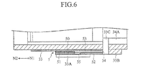
- the casing main body 30 configures a major part of the casing 3, and has an internal space 35 defined by a pair of side walls 32, a rear wall 33 and a lower wall 34.
- Each of the side walls 32 has stoppers 32A, 32B and 32C.
- the stopper 32A interferes with the device retaining part 15 when the device 2 is attached to the device retaining part 15 of the analyzer 1, and protrudes outwardly from the side wall 32. That is, the device 2 has an insertion depth in the device retaining part 15 regulated by the stopper 32A.
- the stopper 32B causes an engaging part 43 of the lancet 4 to be discussed later to interfere, and is for restraining the lancet 4 movable by a fixed distance in directions N1 and N2 together with the lower wall 34. That is, the lancet 4 is movable within a certain range in the directions N1 and N2 in the internal space 35.
- the stopper 32C is for retaining the engaging part 43 together with the stopper 32B, and is for restraining the lancet 4.
- the cover 31 is for interconnecting the pair of side walls 32 together.
- the cover 31 is for restraining the lancet 4 together with the rear wall 33 in a thickness direction in the internal space 35.
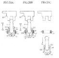
- the cover 31 has a smaller dimension in the directions N1 and N2 than that of the side wall 32, and selectively interconnects only upper parts of the side walls 32 together. Accordingly, the internal space 35 is partially covered, and a part of the internal space 35 is exposed, so that a leading end of the lancet 4 is visually recognizable. That is, an adjoining part of the cover 31 in the direction N1 is an opening 36 for exposing the lancet 4.
- the rear wall 33 has a positioning parts 33A, 33B and a through-hole 33C.
- the positioning part 33A functions as a guide when the biosensor 5 is attached to the casing main body 30, and is for positioning and holding the biosensor 5 when the biosensor 5 is attached.
- the positioning 33B is for defining a position of the biosensor 5 together with the positioning part 33A, and is formed so as to protrude from the rear wall 33.
- the through-hole 33C is for making capillary force effective, and is for supplying a blood to the biosensor 5 together with a suction part 34B of the lower wall 34 to be discussed later.
- the through-hole 33C is provided so as to pass all the way through the rear wall 33, is communicated with the suction part 34B, and is opened in a surface of the rear wall 33.
- the through-hole 33C is communicated with the suction part 34B, and configures a flow path together with the suction part 34B.
- the through-hole 33C permits a blood sucked by the suction part 34B to be supplied therethrough, and to be supplied to the biosensor 5.
- the through-hole 33C can also supply the blood to the biosensor 5 as the blood is directly supplied without flowing through the suction part 34B.
- the lower wall 34 is for regulating a position of the lancet 4 and a moving range thereof in the directions N1 and N2, and has a recess 34A and the suction part 34B.
- the recess 34A is for retaining a narrow part 46 of a cap 41 of the lancet 4 to be discussed later.
- the lower wall 34 is also for allowing a puncture needle 44 in the lancet 4 to move with the cap 41 being detached from the lancet 4. That is, the recess 34A also has a function of making a puncture 41 in a lancet 41 visually recognizable, and configures a part of a visible region.
- the suction part 34B is for suctioning a blood caused to flow out through a skin by capillary force, and is formed in a groove-like shape opened laterally.
- the suction part 34B is communicated with the through-hole 33C, and allows the blood sucked by the suction part 34B to be supplied to the through-hole 33C.
- the casing 3 employs a very simple configuration including the casing main body 30 and the cover 31, and can be easily formed by, for example, resin molding. Accordingly, it becomes possible to suppress any effort of processing the casing 3 and increasing of a cost thereof.
- the lancet 4 is retained in a lancet holder 63 (see FIG. 2 ) in the piercing mechanism 10 to be discussed later, and is used for piercing a skin.
- the lancet 4 has a lancet main body 40, the cap 41 and a brittle part 42,
- the lancet main body 40 is retained in the lancet holder 63 (see FIG. 2 ), and has the engaging part 43 and the puncture needle 44.
- the engaging part 43 is engaged with the stopper 32B of the casing 3, and is for preventing the lancet 4 from carelessly ejecting out from the casing 3 in the direction N2 (see FIG. 4B ).
- the puncture needle 44 is fixed in the lancet main body 40, and has a needle tip 45 protruding from the lancet main body 40.
- the cap 41 is for covering the needle tip 45 of the puncture needle 44, and is detachable from the lancet main body 40.
- the cap 41 When the cap 41 is detached from the lancet 4, as the needle tip 45 of the puncture needle 44 protrudes from the lancet main body 40, the needle tip of the puncture needle 44 is in an exposed condition.
- the cap 41 has the narrow part 46. As shown in FIG. 3A , FIG. 4A and FIG. 5 , the narrow part 46 is retained in the recess 34A of the lower wall 34 of the casing main body 30. With the narrow part 46 being retained in the recess 34A, the position of the lancet 4 relative to the casing main body 30 (the casing 3) is regulated, and the lancet 4 is restrained in the directions N1 and N2.
- the brittle part 42 is for facilitating detachment of the cap 41 from the lancet main body 40.
- the lancet 4 can be formed by inserting the puncture needle 44 therein by resin molding. Moreover, as a sterilizing process is performed on the lancet after the lancet is formed, the lancet 4 can maintain a clean condition until the cap 41 is detached and the needle tip 45 of the puncture needle 44 is exposed. Furthermore, by devising the shape of the casing main body 30 of the casing 3, the existing lancet 4 can be also used. Accordingly, it becomes possible to reduce the production cost of the lancet 4, thereby reducing the production cost of the device 2.
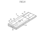
- the biosensor 5 employs a configuration that a cover 52 is stacked on a long-rectangular substrate 50 via a spacer 51.
- a capillary 53 extending in a lengthwise direction of the substrate 50 is defined by each of structural elements 50 to 52 in the biosensor 5.
- the capillary 53 is for moving a blood introduced from an end 54 to a through-hole 55 of the cover 52 using an capillary phenomenon, and is for retaining the introduced blood.
- an acting electrode 56 Formed on an upper face of the substrate 50 are an acting electrode 56, a counter electrode 57 and a reagent part 58.
- the acting electrode 56 and the counter electrode 57 are caused to contact connectors (not illustrated) of the analyzer 1 when the device 2 is attached to the analyzer 1.
- the acting electrode 56 and the counter electrode 57 enable application of a voltage to a blood in the capillary 53, and enable measurement of a response current when the voltage is applied.
- the reagent part 58 is arranged in the interior of the capillary 53, and contains, for example, an electron transferring substance and an oxidoreductase.
- the oxidoreductase are a glucose oxidase (GOD) and a glucose dehydrogenase (GDH) when a glucose in a blood is analyzed, and a PQQGDH is typically used.
- the electron transferring substance are a ruthenium complex and an iron complex, and an [Ru(NH 3 ) 6 ]CI 3 or a K 3 [Fe(CN) 6 ] can be typically used.
- an existing biosensor can be also used by devising the respective positions of the positioning parts 33A and 33B of the casing main body 30 of the casing 3 and the respective shapes thereof. This enables reduction of the production cost of the biosensor 5, thereby reducing the production cost of the device 2.
- the analyzing mechanism 11 is for analyzing a specific constituent in the blood from a response current when the voltage is applied across the acting electrode 56 and the counter electrode 57 (see FIG. 6 and FIG. 8 ).
- the analyzing mechanism 11 has information indicating, for example, a relationship between the response current and a concentration of the specific constituent (e.g., a standard curve or a corresponding table), and enables analysis of the concentration or the like of the specific constituent in the blood by comparing the information with a measured response current.
- the piercing mechanism 10 is used for moving the lancet 4 in the device 2 from a stand-by position to a piercing position to pierce a skin, and is for causing a blood to flow out through the skin.
- the piercing mechanism 10 has a lancet moving mechanism 6 and a latch releasing member 7.
- the lancet moving mechanism 6 has a link member 60, a first moving member 61, a second moving member 62 and the lancet holder 63.
- the lancet moving mechanism 6 converts the reciprocating motion of the first moving member 61 into the reciprocating motion of the lancet holder 63 through the circular motion of the link member 60.
- the link member 60 is for interlocking the second moving member 62 with the movement of the first moving member 61 when the first moving member 61 moves and for moving the second moving member 62.
- the link member 60 has a first movable pin 60A, a second movable pin 60B, a fixed shaft 60C, a first arm 60D and a second arm 60E.
- the first movable pin 60A engages with the first moving member 61, and is for connecting the first arm 60D and the second arm 60E together. More specifically, the first movable pin 60A fixes an end 60Db of the first arm 60D and an end 60Eb of the second arm 60E together in a shifted condition from each other at an end 60Da of the first arm 60D and an end 60Ea of the second arm 60E.
- the second movable pin 60B engages with the second moving member 62, and protrudes in a direction opposite to the first movable pin 60A at the end 60Eb of the second arm 60E.
- the fixed shaft 60C is for fixing the link member 60 rotatable relative to the housing 12, and protrudes in a direction opposite to the first movable pin 60A at the end 60Db of the first arm 60D.
- the first movable pin 60A, the second movable pin 60B and the fixed shaft 60C are connected together via the first arm 60D and the second arm 60E, so that positional relationships among the first movable pin 60A, the second movable pin 60B and the fixed shaft 60C are regulated. More specifically, the first movable pin 60A and the second movable pin 60B have the same distance to the fixed shaft 60C, and are rotatable over a circumference around the fixed shaft 60C with respective phases being shifted.
- the first moving member 61 is movable relative to the housing 12 in the directions N1 and N2, and as shown in FIG. 2 , is connected to the housing 12 via a coil spring 64 (see FIG. 2 ).
- the first moving member 61 has a groove 61A, the operation part 6 1 B, a hook 61C and a push-down part 61D.
- the groove 61A is for allowing the first movable pin 60A of the link member 60 to move.
- the groove 61A has an inclined groove 61Aa extending in a direction inclined to the directions N1 and N2, and a straight line groove 61Ab connected to an end of the inclined groove 61 Aa.
- the inclined groove 61Aa is for rotating the first movable pin 60A when the first moving member 61 is moved in the directions N1 and N2.
- the straight line groove 61Ab is for allowing the first moving member 61 to move in the directions N1 and N2 without rotating the first movable pin 60A.
- the operation part 61B is used when the first moving member 61 is manually moved.
- the operation part 61B has a part protruding outwardly through the slit 16 of the housing 12, and is allowed by the slit 16 to move in the directions N1 and N2 (see FIG. 1 and FIG. 2 ).
- the hook 61C is for latching the first moving member 61 with the housing 12 by engaging with a protruding part 18 of the housing 12.
- the push-down part 61D moves the lancet holder 63 in the direction N1 when the first moving member 61 is moved in the direction N1 below a position (a latching position) where the hook 61C is latched with the protruding part 18 of the housing 12.
- the push-down part 61D protrudes in the direction N1 at a lower part of the first moving member 61, and is movable between a pair of flanges 62B of the second moving member 62 to be discussed later.
- the second moving member 62 is for reciprocating the lancet holder 63 in the directions N1 and N2 when the hook 61C of the first moving member 61 is located above the latching position.
- the second moving member 62 has a groove 62A and the pair of flanges 62B.
- the groove 62A engages with the second movable pin 60B while allowing the rotational motion of the second movable pin 60B.
- the groove 62A is formed in an arc shape, and as the second movable pin 60B engages with the groove 62A with a rotational motion, the second moving member 62 is moved in the directions N1 and N2. That is, when the first moving member 61 is moved in the directions N1 and N2, the second moving member 62 is moved together with the rotational motion of the link member 60 (the first movable pin 60A) in the directions N1 and N2.
- the pair of flanges 62B are for moving the lancet holder 63 in the directions N1 and N2 when the second moving member 62 moves in the directions N1 and N2.
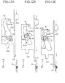
- the flanges 62B are provided so as to interfere with the lancet holder 63 when the hook 61C of the first moving member 61 moves in the directions N1 and N2 above the latching position (see FIG. 12A to FIG. 12C ).
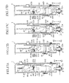
- the pair of flanges 62B are spaced apart from each other, and when the first moving member 61 moves below the latching position in a clearance 62C (see FIG. 14A to FIG. 14C ), the push-down part 61D of the first moving member 61 is allowed to move.
- the lancet holder 63 is for retaining the lancet 4 of the device 2, and is for moving the lancet 4.
- the lancet holder 63 has a pair of engaging parts 63A, a block 63B and a latching part 63C.
- the pair of engaging parts 63A are for retaining the lancet 4, and grooves 63D are formed respectively therein.
- the grooves 63D are for fitting an end of the lancet 4 therein.
- the grooves 63D in the pair of engaging parts 63A are formed at positions facing each other.
- the block 63B is for interfering with the push-down part 61D of the first moving member 61 or the flange 62B of the second moving member 62 (see FIG. 14A to FIG. 14C , or (see FIG. 15A to FIG. 15D )).
- the latching part 63C is for latching with an end 66 of a coil spring 65, and is protrudingly provided from the block 63B.
- the coil spring 65 has an end 67 fixed to the housing 12, and force directed toward the direction N2 acts on the block 63B (the lancet holder 63). That is, the block 63B (the lancet holder 63) is permitted by the coil spring 65 to maintain a condition in which the block contacts the push-down part 61D of the first moving member 61 or the flange 62B of the second moving member 62 (see, FIG. 14A to FIG. 14C , or (see FIG. 15A to FIG. 15D )).
- the lancet holder 63 can be moved in the directions N1 and N2 by the second moving member 62 when the hook 61C of the first moving member 61 is located above the latching position, and as shown in FIG. 14A to FIG. 14C , the lancet holder can be moved in the direction N1 by the first moving member 61 when the hook 61C of the first moving member 61 is located below the latching position.
- the latch releasing member 7 is for releasing a latching condition of the first moving member 61 relative to the housing 12 (the protruding part 18), and has the button 70 and a plate spring 71.
- the button 70 is exposed from the side face of the housing 12, and can wobble.
- the plate spring 71 has moderate elasticity, extends from the button 70 and is fixed to the housing 12 at an end 72.
- the first moving member 61, the second moving member 62, the link member 60 and the lancet holder 63 have respective positional relationships as shown in FIG. 17A .
- the device 2 When a skin is pierced using the analyzer 1, first, the device 2 is retained in the device retaining part 15 of the housing 12. Such an operation is performed by inserting the device 2 into the device retaining part 15. At this time, as the casing 3 of the device 2 is provided with the stopper 32A, the insertion depth (position) of the device 2 is regulated as the stopper 32A interferes with the device retaining part 15 (see FIG. 2 and FIG. 4A ). As the device 2 is larger than the lancet 4 and the biosensor 5, the attachment of the device 2 to the analyzer 1 can be performed easily in comparison with a case in which the lancet 4 and the biosensor 5 are individually attached to the analyzer 1
- the lancet 4 of the device 2 is retained in the lancet holder 63, and the hook 61C of the first moving member 61 is engaged with the protruding part 18 of the housing 12.
- Such an operation is accomplished by pushing down the operation part 61B of the first moving member 61 in the direction N1 by a predetermined distance.
- the hook 61C reaches a position engageable with the protruding part 18 of the housing 12.
- the lancet does not move because the narrow part 46 of the cap 41 is engaging with the recess 34A of the casing main body 30 (see, FIG. 4A ).
- the lancet holder 63 also does not move, and the lancet holder 63 is detached from the first moving member 61.
- the lancet 4 As shown in FIG. 18A and FIG. 18B , with the lancet 4 being retained in the lancet holder 63, when the cap 41 is detached from the lancet 4, the puncture needle 44 is exposed from the lancet main body 40 (see FIG. 7B ). Meanwhile, with regard to the lancet main body 40, as the restraint of the device 4 in the recess 34A of the rear wall 34 in the casing main body 30 is released (see FIG. 4B ), the lancet 4 moves together with the lancet holder 63 in the direction N2 by the elastic force of the coil spring 65. The movement of the lancet 4 in the direction N2 is stopped as the lancet holder 63 interferes with the flange 62B of the second moving member 62.
- the first moving member 61 is connected to the stretched coil spring 64, the first moving member moves in the direction N2 by the elastic force of the coil spring 64.
- the link member 60 rotates around the fixed shaft 60C.
- the second movable pin 60B moves through the groove 62A of the second moving member 62.
- the second moving member 62 moves in the direction N1, and then moves in the direction N2 together with the rotational trajectory of the second movable pin.
- the lancet holder 63 As the lancet holder 63 is connected to the coil spring 65 and interferes with the flange 62B of the second moving member 62, the lancet holder moves together with the second moving member 62. As the lancet 4 is retained in the lancet holder 63, the lancet 4 also moves together with the second moving member 62 in the direction N1, and then moves in the direction N2.
- the puncture needle 44 As the puncture needle 44 is exposed from the lancet 4, when the lancet 4 is moved in the direction N1, the puncture needle 44 protrudes from the casing 3, and pierces the skin 8. Conversely, when the lancet 4 moves in the direction N2, the puncture needle 44 is pulled out from the skin 8, and the piercing operation completes. In this manner, piercing of the skin 8 by the lancet 4 and pulling out of the puncture needle are performed together with the movement of the first moving member 61 in the direction N2.
- a blood flows out through the skin 8.
- the blood is suctioned by the suction part 34B of the lower wall 34 in the casing main body 30.
- a lower part of the lancet 4 is exposed. Accordingly, the user can check the piercing operation of the lancet 4 (the puncture needle 44) to the skin 8 through the casing 3. Consequently, the user can check a flow-out amount of the blood when extracting the blood. Accordingly, the user can check whether or not the flow-out amount is a sufficient amount necessary for the analysis of the blood.
- the blood suctioned by the suction part 34B moves through the through-hole 33C by capillary force, and reaches an end of the capillary 53 (an edge of the through-hole 55 of the cover 52) of the biosensor 5.
- the capillary 53 the blood is moved and retained by the capillary force.
- the blood flowing out through the skin is supplied to the biosensor 5 through the suction part 34B and the through-hole 33C. Accordingly, it is not necessary to position the end 54 of the capillary 53 of the biosensor 5 to a blood flow-out site of the skin 8 and to introduce the blood into the capillary 53 in order to supply the blood to the biosensor 5. Consequently, when the device 2 is used, an effort of introducing the blood into the biosensor 5 can be omitted.
- a specific constituent in the blood is analyzed in the analyzing mechanism 11 (see FIG. 2 ).
- the analysis of the specific constituent is performed by comparing a response current after a certain time when a voltage is applied across the acting electrode of the biosensor 5 and the counter electrode thereof (see FIG. 6 and FIG. 8 ) with information indicating a relationship between a response current and the concentration of the specific constituent. An analysis result at this time is displayed on the display panel 4.
- the device 2 is detached from the device retaining part 15 of the housing 12.
- the device 2 is detached as the device 2 is moved in the direction N1 relative to the housing 12.
- the engaging part 43 of the lancet 4 keeps being restrained between the stopper 32B and the stopper 32C. Accordingly, in the device 2 after the use, the puncture needle 44 of the lancet 4 is prevented from protruding from the casing 3. As a result, the device 2 can be detached and discarded safely and hygienically.
- the detachment of the device 2 from the analyzer 1 can be performed easily in comparison with a case in which the lancet 4 and the biosensor 5 are individually detached from the analyzer 1.
- the first moving member 61 can be easily latched with the protruding part 18 of the housing 12 by pushing down the operation part 61B of the first moving member 61. Meanwhile, in order to pierce a skin, it is fine if the button 70 of the latch releasing member 7 is just pressed. In this manner, the analyzer 1 is convenient for use as the skin can be pierced through very simple operations, such as the downward movement of the operation part 61B and pressing of the button 70. Moreover, when an amount of a blood supplied to the biosensor 5 is insufficient, it is possible to pierce the skin again by downwardly moving the operation part 61B and pressing the button 70 again. Accordingly, it becomes possible to reduce the possibility of occurrence of any measurement error due to lack of a blood, or of any false measurement, and to reduce the number of the devices 2 to be discarded by efficiently using the device 2.
- the analyzer of the present invention and the device 2 thereof are not limited to the above-explained embodiment, and can be changed and modified in various forms.
- the piercing mechanism in the analyzer 1 is not limited to the mechanism employing the link member.
- the biosensor 5 of the device 2 is not limited to an electrode type, and may be a colorimetric type, and may be affixed to a holder via a spacer with a cover being omitted.
- the present invention is not limited to the analyzer, and is further applicable to a puncture device having no analytical function. In this case, the biosensor in the device is omitted.
Landscapes
- Health & Medical Sciences (AREA)
- Life Sciences & Earth Sciences (AREA)
- Physics & Mathematics (AREA)
- Engineering & Computer Science (AREA)
- Animal Behavior & Ethology (AREA)
- General Health & Medical Sciences (AREA)
- Biophysics (AREA)
- Biomedical Technology (AREA)
- Heart & Thoracic Surgery (AREA)
- Medical Informatics (AREA)
- Molecular Biology (AREA)
- Surgery (AREA)
- Veterinary Medicine (AREA)
- Pathology (AREA)
- Public Health (AREA)
- Hematology (AREA)
- Optics & Photonics (AREA)
- Emergency Medicine (AREA)
- Manufacturing & Machinery (AREA)
- Chemical & Material Sciences (AREA)
- Chemical Kinetics & Catalysis (AREA)
- General Chemical & Material Sciences (AREA)
- Dermatology (AREA)
- Measurement Of The Respiration, Hearing Ability, Form, And Blood Characteristics Of Living Organisms (AREA)
Applications Claiming Priority (2)
| Application Number | Priority Date | Filing Date | Title |
|---|---|---|---|
| JP2007328086 | 2007-12-19 | ||
| PCT/JP2008/073263 WO2009078488A1 (ja) | 2007-12-19 | 2008-12-19 | ランセットデバイスおよび穿刺装置 |
Publications (1)
| Publication Number | Publication Date |
|---|---|
| EP2243426A1 true EP2243426A1 (de) | 2010-10-27 |
Family
ID=40795599
Family Applications (1)
| Application Number | Title | Priority Date | Filing Date |
|---|---|---|---|
| EP08862071A Withdrawn EP2243426A1 (de) | 2007-12-19 | 2008-12-19 | Lanzettenvorrichtung und einstichvorrichtung |
Country Status (5)
| Country | Link |
|---|---|
| US (1) | US20100305597A1 (de) |
| EP (1) | EP2243426A1 (de) |
| JP (1) | JPWO2009078488A1 (de) |
| CN (2) | CN101902962A (de) |
| WO (1) | WO2009078488A1 (de) |
Families Citing this family (1)
| Publication number | Priority date | Publication date | Assignee | Title |
|---|---|---|---|---|
| TW201212887A (en) * | 2010-07-08 | 2012-04-01 | Sanofi Aventis Deutschland | Eliciting a blood sample |
Family Cites Families (9)
| Publication number | Priority date | Publication date | Assignee | Title |
|---|---|---|---|---|
| DE19824036A1 (de) | 1997-11-28 | 1999-06-02 | Roche Diagnostics Gmbh | Analytisches Meßgerät mit Stechhilfe |
| JPH11206742A (ja) * | 1998-01-22 | 1999-08-03 | Terumo Corp | 穿刺具 |
| JP2000014662A (ja) * | 1998-01-22 | 2000-01-18 | Terumo Corp | 体液検査装置 |
| JP3668382B2 (ja) * | 1998-11-19 | 2005-07-06 | テルモ株式会社 | 成分測定装置 |
| JP2000225110A (ja) * | 1999-02-09 | 2000-08-15 | Terumo Corp | 穿刺具 |
| JP3742741B2 (ja) * | 1999-12-16 | 2006-02-08 | テルモ株式会社 | 体液検査装置 |
| JP2004033376A (ja) | 2002-07-01 | 2004-02-05 | Terumo Corp | 穿刺針一体型体液採取具 |
| JP4233496B2 (ja) * | 2004-06-17 | 2009-03-04 | テルモ株式会社 | 体液検査装置 |
| US8105244B2 (en) * | 2005-11-30 | 2012-01-31 | Abbott Diabetes Care Inc. | Integrated sensor for analyzing biological samples |
-
2008
- 2008-12-19 EP EP08862071A patent/EP2243426A1/de not_active Withdrawn
- 2008-12-19 CN CN2008801218976A patent/CN101902962A/zh active Pending
- 2008-12-19 CN CN201210075880XA patent/CN102631200A/zh active Pending
- 2008-12-19 US US12/735,169 patent/US20100305597A1/en not_active Abandoned
- 2008-12-19 JP JP2009546305A patent/JPWO2009078488A1/ja not_active Abandoned
- 2008-12-19 WO PCT/JP2008/073263 patent/WO2009078488A1/ja not_active Ceased
Non-Patent Citations (1)
| Title |
|---|
| See references of WO2009078488A1 * |
Also Published As
| Publication number | Publication date |
|---|---|
| WO2009078488A1 (ja) | 2009-06-25 |
| CN102631200A (zh) | 2012-08-15 |
| JPWO2009078488A1 (ja) | 2011-05-06 |
| CN101902962A (zh) | 2010-12-01 |
| US20100305597A1 (en) | 2010-12-02 |
Similar Documents
| Publication | Publication Date | Title |
|---|---|---|
| US8323212B2 (en) | Attachment for body fluid sampling device and method of making the same | |
| EP1541087B1 (de) | Vorrichtung zur entnahme von körperflüssigkeit | |
| KR100893275B1 (ko) | 일체식 샘플 시험용 계측기 | |
| CN101346101B (zh) | 血液检查装置 | |
| EP2100560B1 (de) | Prüfsensor mit dünner Lanzette | |
| US8328735B2 (en) | Analytical system for detecting an analyte in a body fluid and disposable integrated puncturing and analyzing element | |
| US8647575B2 (en) | Device for measuring blood component | |
| WO2005039413A1 (ja) | ランセットおよび穿刺装置 | |
| JP4143753B2 (ja) | 取り出し機構を備えた分析用具カートリッジ、およびこれと分析装置のセット | |
| CN101336092A (zh) | 传感器-刺血针一体型器件、以及使用其的体液采集方法 | |
| JP2013500126A5 (de) | ||
| TW201206400A (en) | Allowing measurements to be made of a blood sample | |
| JP2000152923A (ja) | 成分測定装置 | |
| CN104159511B (zh) | 用于引出血液样本的装置 | |
| CN104010572B (zh) | 液体试料测定装置 | |
| JPH1028683A (ja) | ランセット一体型血糖値測定器 | |
| US20100305597A1 (en) | Lancet device and puncture device | |
| EP1637078A1 (de) | Körperflüssigkeitsentnahme-vorrichtung und körperflüssigkeitsentnahme-verfahren | |
| EP1875230A1 (de) | marker für bei tests an alternativen stellen vorgenommene ablesevorgänge | |
| JP2000116626A (ja) | 体液測定装置および装着体 | |
| JP2007301105A (ja) | 測定器用ホルダ及びバイオセンサ測定器 | |
| EP3706910B1 (de) | Analysevorrichtung mit einem gehäuse und halter für eine probenaufnahmevorrichtung | |
| JP4635140B2 (ja) | ランセット一体型体液測定装置およびこの体液測定装置に装着して使用する装着体 | |
| WO2012060400A1 (ja) | 体液成分測定装置 | |
| JP2008154952A (ja) | バイオセンサ用試料採取器具及びバイオセンサシステム |
Legal Events
| Date | Code | Title | Description |
|---|---|---|---|
| PUAI | Public reference made under article 153(3) epc to a published international application that has entered the european phase |
Free format text: ORIGINAL CODE: 0009012 |
|
| 17P | Request for examination filed |
Effective date: 20100714 |
|
| AK | Designated contracting states |
Kind code of ref document: A1 Designated state(s): AT BE BG CH CY CZ DE DK EE ES FI FR GB GR HR HU IE IS IT LI LT LU LV MC MT NL NO PL PT RO SE SI SK TR |
|
| AX | Request for extension of the european patent |
Extension state: AL BA MK RS |
|
| DAX | Request for extension of the european patent (deleted) | ||
| STAA | Information on the status of an ep patent application or granted ep patent |
Free format text: STATUS: THE APPLICATION HAS BEEN WITHDRAWN |
|
| 18W | Application withdrawn |
Effective date: 20120927 |