EP3706910B1 - Analysevorrichtung mit einem gehäuse und halter für eine probenaufnahmevorrichtung - Google Patents
Analysevorrichtung mit einem gehäuse und halter für eine probenaufnahmevorrichtung Download PDFInfo
- Publication number
- EP3706910B1 EP3706910B1 EP18800887.4A EP18800887A EP3706910B1 EP 3706910 B1 EP3706910 B1 EP 3706910B1 EP 18800887 A EP18800887 A EP 18800887A EP 3706910 B1 EP3706910 B1 EP 3706910B1
- Authority
- EP
- European Patent Office
- Prior art keywords
- microcuvette
- analysis apparatus
- holder
- activating
- acquiring device
- Prior art date
- Legal status (The legal status is an assumption and is not a legal conclusion. Google has not performed a legal analysis and makes no representation as to the accuracy of the status listed.)
- Active
Links
Images



Classifications
-
- B—PERFORMING OPERATIONS; TRANSPORTING
- B01—PHYSICAL OR CHEMICAL PROCESSES OR APPARATUS IN GENERAL
- B01L—CHEMICAL OR PHYSICAL LABORATORY APPARATUS FOR GENERAL USE
- B01L9/00—Supporting devices; Holding devices
- B01L9/06—Test-tube stands; Test-tube holders
- B01L9/065—Test-tube stands; Test-tube holders specially adapted for capillary tubes
-
- G—PHYSICS
- G01—MEASURING; TESTING
- G01N—INVESTIGATING OR ANALYSING MATERIALS BY DETERMINING THEIR CHEMICAL OR PHYSICAL PROPERTIES
- G01N21/00—Investigating or analysing materials by the use of optical means, i.e. using sub-millimetre waves, infrared, visible or ultraviolet light
- G01N21/01—Arrangements or apparatus for facilitating the optical investigation
- G01N21/13—Moving of cuvettes or solid samples to or from the investigating station
-
- G—PHYSICS
- G01—MEASURING; TESTING
- G01N—INVESTIGATING OR ANALYSING MATERIALS BY DETERMINING THEIR CHEMICAL OR PHYSICAL PROPERTIES
- G01N35/00—Automatic analysis not limited to methods or materials provided for in any single one of groups G01N1/00 - G01N33/00; Handling materials therefor
- G01N35/10—Devices for transferring samples or any liquids to, in, or from, the analysis apparatus, e.g. suction devices, injection devices
- G01N35/1081—Devices for transferring samples or any liquids to, in, or from, the analysis apparatus, e.g. suction devices, injection devices characterised by the means for relatively moving the transfer device and the containers in an horizontal plane
-
- B—PERFORMING OPERATIONS; TRANSPORTING
- B01—PHYSICAL OR CHEMICAL PROCESSES OR APPARATUS IN GENERAL
- B01L—CHEMICAL OR PHYSICAL LABORATORY APPARATUS FOR GENERAL USE
- B01L3/00—Containers or dishes for laboratory use, e.g. laboratory glassware; Droppers
- B01L3/50—Containers for the purpose of retaining a material to be analysed, e.g. test tubes
- B01L3/508—Rigid containers without fluid transport within
-
- B—PERFORMING OPERATIONS; TRANSPORTING
- B01—PHYSICAL OR CHEMICAL PROCESSES OR APPARATUS IN GENERAL
- B01L—CHEMICAL OR PHYSICAL LABORATORY APPARATUS FOR GENERAL USE
- B01L9/00—Supporting devices; Holding devices
- B01L9/06—Test-tube stands; Test-tube holders
-
- B—PERFORMING OPERATIONS; TRANSPORTING
- B01—PHYSICAL OR CHEMICAL PROCESSES OR APPARATUS IN GENERAL
- B01L—CHEMICAL OR PHYSICAL LABORATORY APPARATUS FOR GENERAL USE
- B01L2200/00—Solutions for specific problems relating to chemical or physical laboratory apparatus
- B01L2200/02—Adapting objects or devices to another
- B01L2200/025—Align devices or objects to ensure defined positions relative to each other
-
- B—PERFORMING OPERATIONS; TRANSPORTING
- B01—PHYSICAL OR CHEMICAL PROCESSES OR APPARATUS IN GENERAL
- B01L—CHEMICAL OR PHYSICAL LABORATORY APPARATUS FOR GENERAL USE
- B01L2200/00—Solutions for specific problems relating to chemical or physical laboratory apparatus
- B01L2200/10—Integrating sample preparation and analysis in single entity, e.g. lab-on-a-chip concept
-
- B—PERFORMING OPERATIONS; TRANSPORTING
- B01—PHYSICAL OR CHEMICAL PROCESSES OR APPARATUS IN GENERAL
- B01L—CHEMICAL OR PHYSICAL LABORATORY APPARATUS FOR GENERAL USE
- B01L2300/00—Additional constructional details
- B01L2300/08—Geometry, shape and general structure
- B01L2300/0809—Geometry, shape and general structure rectangular shaped
-
- G—PHYSICS
- G01—MEASURING; TESTING
- G01N—INVESTIGATING OR ANALYSING MATERIALS BY DETERMINING THEIR CHEMICAL OR PHYSICAL PROPERTIES
- G01N21/00—Investigating or analysing materials by the use of optical means, i.e. using sub-millimetre waves, infrared, visible or ultraviolet light
- G01N21/01—Arrangements or apparatus for facilitating the optical investigation
- G01N21/13—Moving of cuvettes or solid samples to or from the investigating station
- G01N2021/135—Sample holder displaceable
Definitions
- the invention relates to a sample acquiring device holder to be inserted into a housing of an analysis apparatus. Furthermore, the invention relates to an analysis apparatus comprising the aforesaid housing and sample acquiring device holder, wherein the analysis apparatus may be adapted to conduct a quantitative hemoglobin determination in undiluted, unhemolyzed whole blood. Additionally, the invention relates to a method for analysing a blood sample which is stored within a sample acquiring device.
- the sample acquiring device may be a microcuvette comprising two interspaced transparent plates, and the blood sample may be stored within the plates.
- the sample acquiring device may be inserted into a blood analysis apparatus for analysis such as hemoglobin determination, blood glucose determination or white blood cell count.
- SE 538371 C2 discloses a type of a sample acquiring device holder, which is intended to be pushed into an analyzer and then to be pushed slightly to open it again.
- DE 10 2007 059167 A1 discloses an pipette tip for use in an optical measuring device.
- analysis apparatuses which comprise a sample acquiring device holder.
- an operator of such analysis apparatuses has to open up the holder, put the sample acquiring device in the designated place on the holder, then close the holder, wait for measurement to be made, open the holder again and remove the sample acquiring device from the holder.
- This procedure may be acceptable, if the measurement time is e.g. 10-60 seconds long. In this case it may be acceptable to add the time for opening and closing the holder and put down the sample acquiring device.
- a sample acquiring device holder for a housing of an analysis apparatus.
- the sample acquiring device holder comprises an activating element and a reception recess for receiving a sample acquiring device.
- a first portion of the activating element protrudes into the reception recess, if the activating element is in a non-activating position.
- the activating element is adapted to be moved into an activating position by the sample acquiring device, if the sample acquiring device is inserted into an intended measurement position within the reception recess.
- the activating element is adapted to activate a measurement triggering element, if the activating element is in its activating position, such that the measurement triggering element activates a measurement of the analysis apparatus.
- the measurement especially may include an analysis of a sample stored within the sample acquiring device.
- the first portion of the activating element protrudes into the reception recess, the first portion forms an obstacle which partially blocks the path of the sample acquiring device on the way to its intended measurement position.
- the first portion of the activating element can be pushed out of the way, especially out of the reception recess, by the sample acquiring device.
- the activating element may be an elastic and flexible part.
- the sample acquiring device may push away the first portion of the activating element in a direction towards the measurement triggering element.
- the activating element may be brought into its activating position out of a non-activating position.
- the activating element may push the measurement triggering element, especially a button. By pushing the measurement triggering element, a measurement of the analysis apparatus may be activated.
- the sample acquiring device holder enables that a measurement will not start unless the sample acquiring device with the blood sample is in the correct position. You cannot start a measurement if you accidently come in contact with another part of the analysis apparatus. Thus, an unintentional activation of a measuring may be prevented, as the sample acquiring device must be in its correct (i.e. in its intended) measurement position to do so.
- the sample acquiring device holder also enables to shorten the measurement duration and, thus, to increase speed.
- An operator e.g. a nurse
- An operator of the analysis apparatus does not have to let go of the sample acquiring device when performing a measurement.
- the operator handles the analysis apparatus close to a patient. So, the operator can e.g. prick a fingertip of the patient, fill a sample acquiring device with blood from the fingertip and then push the sample acquiring device into the sample acquiring device holder being inserted within the analyzing apparatus. After the measurement has been completed, the operator may simply and quickly pull the sample acquiring device out of the sample acquiring device holder, while the results of the measurement will be available immediately.
- the operator can hold the sample acquiring device the whole time from pricking the patient's fingertip to throwing the sample acquiring device away after having completed the measurement procedure.
- the effect of not being able to start a measurement before the sample acquiring device is in the correct position ensures that no erroneous results are shown to the operator. Either the sample acquiring device is in the correct place and you will obtain a result, or the sample acquiring device is not in the correct place and no measurement will be performed.
- the activating element comprises an arm shaped element.
- the arm shaped element can comprise an upper arm element and a forearm element.
- the upper arm element and the forearm element can be connected in an elbow portion of the arm shaped element in a one-piece manner, especially rigidly.
- a first end portion of the arm shaped element, especially a distal end portion of the forearm element protrudes into the reception recess, especially close to a bottom area of the housing.
- a second end portion of the arm shaped element, especially a distal end portion of the upper arm element can be connected - pivotably or at least substantially rigidly - with an upper part of the reception part.
- the elbow portion of the arm shaped element is adapted to activate the measurement triggering element, if the activating element is in its activating position, such that the measurement triggering element activates a measurement of the analysis apparatus.
- This embodiment provides a simple and reliably mechanical construction for detecting the correct position of the sample acquiring device and for automatically starting an analysis of a sample stored within the sample acquiring device.
- the activating element may be a simple bar.
- the bar may comprise a chamfered end portion which protrudes into the reception recess of the sample acquiring device holder and which is directed to a sample acquiring device.
- the sample acquiring device may push the chamfered end portion of the bar, such that the bar is moved towards the measuring triggering element and pushes the latter to start the measuring of the analysis apparatus.
- the analysis apparatus may comprise a spring element which is adapted to move the bar back, such that the chamfered end portion protrudes into the reception recess again.
- the sample acquiring device holder can further comprise a reception part which forms the reception recess for receiving the sample acquiring device.
- the reception part can be made of a plastic material.
- the activating element, especially the arm shaped element, can be attached to the reception part in a one-piece manner.
- the activating element can be made of the same material as the reception part, especially made of a plastic material. Said attachment can especially be implemented in a substantially rigidly manner.
- the activating element especially the arm shaped element, may comprise a first plastic material and a second plastic material being different from the first plastic material.
- the second plastic material can be included along the activating element, especially along the arm shaped element. This contributes to make the activating element, especially the arm shaped element, more flexible.
- the reception part can be made of a first material and the activating element, especially the arm shaped element, can be made of a second material.
- the first material can be a first plastic material
- the second material can be a second plastic material.
- the first plastic material can be a different material than the second plastic material, such that the activating element, especially the arm shaped element is provided with high flexibility.
- the first plastic material also be the same than the second plastic material.
- the activating element is pivotably attached to the reception part.
- the activating element especially the arm shaped element, to the reception part, flexibility of the activation element can be enhanced.
- the activating element can be pivotably attached to the reception part by means of a hinge.
- This hinge can be a separate hinge which is connected to the reception part on the one side and to the activating element, especially the arm shaped element, on the other side.
- the hinge can be formed by the reception part and by the activating element, especially by the arm shaped element.
- the activating element, especially the arm shaped element can form a shaft while the reception part forms a socket for accommodating the shaft.
- Both the activating element, especially the arm shaped element, and the reception part can be made of a same plastic material.
- a metal pin may be attached to the reception part.
- the activating element may be made of a plastic material and may comprise a recess corresponding to the size and shape of the pin. Further, the pin may be inserted into the recess such that the activating element is pivotably attached to the reception part.
- the activating element may be made of a metal material, and the activating element may be attached to the reception part, especially in a rigid manner.
- the reception part may be made of a plastic material.
- the metal activating element comprises a particularly high stability and elasticity.
- the metal activating element can be made relatively thin, especially compared to an activating element made of a plastic material.
- the sample acquiring device must be inserted into a compartment.
- This compartment usually is accessible only, if an opening/closing element is brought into an open position, whereas - when brought into a closed position - the opening/closing element closes the compartment such that the sample acquiring device cannot be inserted into the compartment.
- the compartment may be formed and arranged such that it provides a space for a accommodating of the sample acquiring device in its intended measurement position within the analysis apparatus, wherein the opening/closing element may secure the sample acquiring device in its intended measurement position within the analysis apparatus.
- this process of opening the opening/closing element, inserting the sample acquiring device into the compartment in the intended position and closing the opening/closing element again may take a lot of time.
- the sample acquiring device holder may further comprise a guiding structure.
- the guiding structure may comprise a first rail and a second rail, wherein the first rail of the guiding structure of the sample acquiring device holder corresponds to a first groove of the sample acquiring device and wherein the second rail of the guiding structure of the sample acquiring device holder corresponds to a second groove of the sample acquiring device.
- the guiding structure may comprise a first groove and a second groove, wherein the first groove of the guiding structure of the sample acquiring device holder corresponds to a first rail of the sample acquiring device and wherein the second groove of the guiding structure of the sample acquiring device holder corresponds to a second rail of the sample acquiring device.
- the guiding structure may be adapted for inserting the sample acquiring device into the intended measurement position within the reception recess, such that the sample acquiring device protrudes out of the sample acquiring device holder and out of the analysis apparatus, if the sample acquiring device is in its intended measurement position within the reception recess.
- This embodiment enables that the sample acquiring device only must be introduced into the guiding structure and to be pushed into the sample acquiring device holder, until the sample acquiring device is in its intended measurement position. This can be done in a single step. Because the sample acquiring device still protrudes out of the sample acquiring device holder and the analysis apparatus when being brought into its intended measurement position, the sample acquiring device can be inserted manually without any tools or aids. By means of the activating element it can be easily ensured, that the sample acquiring device is in its intended measurement position within the sample acquiring device holder and within the analysis apparatus, also. It is no longer necessary to laboriously open and close an opening/closing element to bring and secure the sample acquiring device in its intended position.
- the analysis apparatus further comprises a magnet detecting element, e.g. a metal bar.
- the magnet detecting element is adapted to detect a magnetic field of a magnet of the sample acquiring device holder.
- the analysis apparatus may be ready for a measurement, when the sample acquiring device holder is arranged within the recess of the housing. This simple arrangement of a magnet and a magnet detecting element enables a reliable detection, whether the sample acquiring device holder is arranged within the sample acquiring device holder and within the analysis apparatus, or not.
- the analysis apparatus can automatically switch over into a "ready to measure” modus, if the analysis apparatus detects, that the sample acquiring device holder is within the recess of the housing (or that the magnet is within the sensing range of the magnet detecting element). If then a sample acquiring device is pushed into the reception recess of the sample acquiring device holder, such that the sample acquiring device is its intended measurement position, the measurement will be started by the activating device which pushes the measurement triggering device.
- a method for analysing a blood sample which is stored within a sample acquiring device may comprise providing an analysis apparatus according to the second aspect of the invention.
- the sample acquiring device holder of the analysis apparatus may be inserted into the housing of the analysis apparatus.
- a sample acquiring device may be provided, wherein a blood sample may be stored within the sample acquiring device.
- the sample acquiring device may be inserted into the intended position within the reception recess of the sample acquiring device holder. Thereby, the activating element of the sample acquiring device holder is moved into its activating position by the sample acquiring device, such that the activating element activates the measurement triggering element of the analysis apparatus.
- the measurement triggering element activates a measurement of the analysis apparatus.
- the analysis of the blood sample may include a hemoglobin determination, blood glucose determination or a white blood cell count.
- the analysis may comprise a quantitative hemoglobin determination in undiluted, unhemolyzed whole blood. Such a determination method is described e.g. in EP 1 456 649 B1 of the applicant.
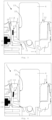
- Figs. 1 and 2 show a part of an analysis apparatus 1, a housing 2, a sample acquiring device holder 3 and a sample acquiring device 4.
- the sample acquiring device holder 3 is removably accommodated within a recess 25 of the housing 2.
- the sample acquiring device 4 is a microcuvette.
- the sample acquiring device is referred to as a "microcuvette 4" in the following.
- the sample acquiring device holder is referred to as a "microcuvette holder 3" in the following.
- the sample acquiring device alternatively also may be e.g. a spectrophotometry cuvette, a sample tube or an EPPENDORF ® tube, and especially the sample acquiring device holder 3 may be designed to receive such an alternative sample acquiring device as will be described in the following.
- the microcuvette holder 3 comprises an activating element 5.
- the activating element comprises an arm shaped element with an upper arm element 6 and a forearm element 7.
- the upper arm element 6 and the forearm element 7 are connected in an elbow portion 8 of the arm shaped element in a one-piece manner.
- a first end portion 10 of the arm shaped element in the shown embodiment a distal end portion 10 of the forearm element 7, protrudes into a reception recess 11, which is formed by a reception part 12 of the microcuvette holder 3.
- the shape and dimensions are designed such that the microcuvette 4 can be pushed into the reception recess 11 to start a measurement and also to be pulled out of the reception recess 11 again.
- a second end portion 13 of the arm shaped element is connected with an upper part, which may be called a shoulder part 14, of the reception part 12 in a one-piece manner.
- the second end portion 13 of the arm shaped element may be substantially rigidly connected to the shoulder part 14 of the reception part 12 of the microcuvette holder 3, the arm shaped element may be a flexible and elastic part that may be pivoted to some extent around the shoulder part 14.
- the reception part 12 of the microcuvette holder 3 provides a guiding structure 22, in the shown example in form of two inner guiding surfaces each corresponding to an outer side surface 23 of the microcuvette 4 (see also Fig. 14 ).
- the guiding structure e.g. may be comprise at least one rail or groove corresponding to a groove respectively rail of the microcuvette 4.
- the guiding structure 22 is adapted for guiding the microcuvette 4 while the microcuvette 4 is inserted into the intended measurement position within the reception recess 11.
- the guiding structure 22 is adapted to guide the microcuvette 4 when being inserted into the microcuvette holder 3, such that the microcuvette 4 protrudes out of the microcuvette holder 3 and out of the analysis apparatus 1, if the microcuvette 4 is in its intended measurement position within the reception recess 11, as it is shown in Fig. 2 .
- the microcuvette 4 only must be introduced and pushed into the guiding structure of the microcuvette holder 3 until the microcuvette 4 is in its intended position. As will be described in the following, this is sufficient to correctly insert the microcuvette 4 into the measurement apparatus 1 and to start a measurement.
- the microcuvette holder 3 with its arm shaped element and with its reception part 12 is made of a plastic material.
- the microcuvette 4 is not in contact with the distal end portion 10 of the forearm element 7 and is not yet pushed as far into the reception recess 11 as to reach its intended measurement position.
- the arm shaped element is in a non-activating position, in which the distal end portion 10 of the forearm element 7 is an obstacle which partially blocks the path of the microcuvette 4 on the way to its intended measurement position.
- the arm shaped element may be an elastic and flexible part.
- the microcuvette 4 can push away the distal end portion 10 of the forearm element 7 in a lateral direction (to the left in Figs. 1 and 2 ) when being pushed further into the reception recess 11, as it is shown in Fig. 2 , which shows the microcuvette 4 is in its intended measurement position.
- the arm shaped element may be pivoted around the shoulder part 14 clockwise according to Figs. 1 and 2 . Thereby, especially the elbow portion 8 may be moved laterally (to the left in Figs. 1 and 2 ).
- the elbow portion 8 may push a measurement triggering element, in the shown example a button 15.
- a measurement of the analysis apparatus 1 may be activated.
- a membrane 16 is positioned between the elbow portion 8 and the button 15 in the shown example.
- the elbow portion 8 may push the button 15 indirectly via the membrane 16.
- the analysis apparatus 1 may be adapted to analyse a blood sample which is stored within the microcuvette 4, when the microcuvette 4 is in its intended measurement position within the reception recess 11 of the microcuvette holder 3.
- the analysis of the blood sample may include a hemoglobin determination, blood glucose determination or a white blood cell count.
- the analysis apparatus 1 may be adapted to conduct a quantitative hemoglobin determination in undiluted, unhemolyzed whole blood as described e.g. in EP 1 456 649 B1 of the applicant.
- the analysis apparatus may be adapted to analyse plasma, serum, urine, milk, waste water or similar substances which are stored within a sample acquiring device inserted within the reception recess of the sample acquiring device holder.
- the embodiment shown by Figs. 3 and 4 substantially has the same functionality than that as per Fig. 1 and 2 .
- the upper arm element 6 as per Figs. 3 and 4 is thicker.
- the arm shaped element as per Figs. 3 and 4 comprises a first plastic material, which builds the forearm element 7 and the elbow portion 8.
- the reception part 12 may be made of the first plastic material, too.
- the upper arm element 6 may be substantially made of the first plastic material.
- a flexibility portion 17 extending along the upper arm element 6 may be made of a second plastic material which is different from the first plastic material. This second plastic material may contribute to make the arm shaped element more flexible.
- the embodiment shown by Figs. 5 and 6 substantially has the same functionality than that as per Fig. 1 and 2 .
- the arm shaped element is pivotably attached to the shoulder part 14 of the reception part 12.
- the upper arm element 6 is pivotably attached to the shoulder part 14 by means of a hinge 18.
- the hinge 18 is formed by the upper arm element 6 and by the shoulder part 14.
- the upper arm element 6 forms a shaft 19 and the shoulder part 14 forms a socket 20 for accommodating the shaft.
- Both the arm shaped element and the reception part 12 can be made of a same plastic material.
- Figs. 7 and 8 as well as 9 and 10 also show embodiments according to which the arm shaped element is pivotably attached to the shoulder part 14 of the reception part 12 by means of a hinge.
- the shoulder part 14 forms a metal pin 19 and upper arm element 6 forms a socket 20 for accommodating the pin.
- the rest of the arm shaped element and the reception part 12 can be made of a same plastic material.
- Figs. 11 and 12 show an embodiment, wherein the arm shaped element is made of a metal material.
- the upper arm element 6 of the arm shaped element is rigidly attached to the shoulder part 14 of the reception part 12.
- the metal activating element 5 comprises a particularly high stability and elasticity.
- the metal activating element 5 can be made relatively thin, especially compared to an activating element 5 made of a plastic material as per Figs. 1 to 10 .
- the reception part 12 can be made of a plastic material.
- Fig. 13 shows another analysis apparatus 1 which substantially has the same functionality than that as per Fig. 1 and 2 .
- the analysis apparatus as per Fig. 13 may comprise a magnet detecting element, in the shown example in the form of a metal bar 21.
- the metal bar 21 is accommodated within a recess of the housing 2.
- the microcuvette holder 3 may comprise a magnet 24.
- the magnet 24 is accommodated within a recess formed by the reception part 12.
- Fig. 13 depicts the microcuvette holder 3 being inserted into an intended position within the recess 25 of the housing 2 of the analysis apparatus 1. In this position, the magnet 24 is in vicinity of the metal bar 21, such that a magnetic field of the magnet 24 may be detected by the metal bar.
- the analysis apparatus 1 may be adapted to detect the magnet 24 of the microcuvette holder 3, when the microcuvette holder 3 is arranged within the recess 25 of the housing 2. If the analysis apparatus 1 detects this, it may automatically switch over into a modus, in which the analysis apparatus 1 is ready for a measurement.
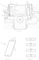
- Fig. 14 shows a microcuvette 4 suitable and adapted for being used in one of the microcuvette holders 3 and analysis apparatuses as per Figs. 1 to 13 .
- Fig. 15 shows a flow chart of a method for analysing a blood sample which is stored within a sample acquiring device 4.
- an analysis apparatus 1 as per one of the Figs. 1 to 13 is provided.
- a microcuvette holder 3 is inserted into the recess 25 of the housing 2 of the analysis apparatus 1.
- a microcuvette 4 is provided, e.g. a microcuvette 4 as per Figs. 1 to 12 or 14 , wherein a blood sample is stored within the microcuvette 4.
- a fourth step 400 the microcuvette 4 is inserted into the intended position within the reception recess 11 of the microcuvette holder 3.
- the arm shaped element of the microcuvette holder 3 is brought into its activating position by the microcuvette 4.
- the elbow portion 5 pushes the button 15, such that the button 15 activates a measurement of the analysis apparatus 1.
- the measurement may include an analysis of the blood sample, e.g. a hemoglobin determination, blood glucose determination or a white blood cell count.
- the analysis may comprise a quantitative hemoglobin determination in undiluted, unhemolyzed whole blood. Such a determination method is described e.g. in EP 1 456 649 B1 of the applicant.
Landscapes
- Health & Medical Sciences (AREA)
- Chemical & Material Sciences (AREA)
- Analytical Chemistry (AREA)
- General Health & Medical Sciences (AREA)
- Chemical Kinetics & Catalysis (AREA)
- Clinical Laboratory Science (AREA)
- Biochemistry (AREA)
- Life Sciences & Earth Sciences (AREA)
- General Physics & Mathematics (AREA)
- Immunology (AREA)
- Pathology (AREA)
- Physics & Mathematics (AREA)
- Hematology (AREA)
- Investigating Or Analysing Biological Materials (AREA)
- Automatic Analysis And Handling Materials Therefor (AREA)
- Investigating Or Analysing Materials By Optical Means (AREA)
- Analysing Materials By The Use Of Radiation (AREA)
Claims (12)
- Analysevorrichtung (1), umfassendein Gehäuse (2),einen Mikroküvettenhalter (3), undein Messauslöseelement (15), insbesondere eine Taste (15),wobei der Mikroküvettenhalter (3)ein Aktivierungselement (5) undeine Aufnahmeausnehmung (11) zum Aufnehmen einer Mikroküvette (4) umfasst,wobei ein erster Abschnitt (10) des Aktivierungselements (5) in die Aufnahmeausnehmung (11) hineinragt, wenn sich das Aktivierungselement (5) in einer Nicht-Aktivierungsposition befindet,wobei das Aktivierungselement (5) dazu angepasst ist, durch die Mikroküvette (4) in eine Aktivierungsposition bewegt zu werden, wenn die Mikroküvette (4) in eine vorgesehene Messposition innerhalb der Aufnahmeausnehmung (11) eingesetzt ist,wobei das Aktivierungselement (5) dazu angepasst ist, das Messauslöseelement (15) durch eine seitliche Bewegung des Aktivierungselements (5) zu aktivieren, wenn sich das Aktivierungselement (5) in seiner Aktivierungsposition befindet, so dass das Messauslöseelement (15) eine Messung der Analysevorrichtung (1) aktiviertwobei das Aktivierungselement (5) ein armförmiges Element umfasst,wobei ein erster Endabschnitt (10) des armförmigen Elements in die Aufnahmeausnehmung (11) hineinragt,wobei ein Winkelabschnitt (8) des armförmigen Elements dazu angepasst ist, das Messauslöseelement (15) durch Drücken zu aktivieren, wenn sich das armförmige Element in seiner Aktivierungsposition befindet, so dass das Messauslöseelement (15) eine Messung der Analysevorrichtung (1) aktiviert,wobei der Mikroküvettenhalter (3) dazu angepasst ist, in einer Aussparung (25) des Gehäuses (2) herausnehmbar untergebracht zu werden,wobei die Analysevorrichtung (1) ein Magneterfassungselement (21) umfasst, wobei das Magneterfassungselement (21) dazu angepasst ist, einen Magneten (24) des Mikroküvettenhalters (3) zu erfassen, undwobei die Analysevorrichtung (1) für eine Messung bereit ist, wenn der Mikroküvettenhalter (3) innerhalb der Aussparung (25) des Gehäuses (2) angeordnet ist.
- Analysevorrichtung (1) nach Anspruch 1,wobei der Mikroküvettenhalter (3) ein Aufnahmeteil (12) umfasst, das die Aufnahmeausnehmung (11) zum Aufnehmen der Mikroküvette (4) bildet, undwobei das Aktivierungselement (5) auf einstückige Weise an dem Aufnahmeteil (12) des Mikroküvettenhalters (3) befestigt ist,wobei das Aufnahmeteil (12) ein Schulterteil (14) umfasst, an dem das Aktivierungselement (5) befestigt ist.
- Analysevorrichtung (1) nach Anspruch 2,
wobei das Aufnahmeteil (12) und das Aktivierungselement (5) aus einem gleichen Kunststoffmaterial hergestellt sind. - Analysevorrichtung (1) nach einem der vorstehenden Ansprüche, wobei das Aktivierungselement (5) ein erstes Kunststoffmaterial und ein
zweites Kunststoffmaterial (17) umfasst, das sich von dem ersten Kunststoffmaterial unterscheidet. - Analysevorrichtung (1) nach einem der vorstehenden Ansprüche,wobei der Mikroküvettenhalter (3) ein Mikroküvettenaufnahmeteil (12) umfasst, das die Aufnahmeausnehmung (11) zum Aufnehmen der Mikroküvette (4) bildet, undwobei das Aktivierungselement (5) schwenkbar am Aufnahmeteil (12) befestigt ist.
- Analysevorrichtung (1) nach Anspruch 5,wobei das Aktivierungselement (5) mittels eines Scharniers (18) schwenkbar am Aufnahmeteil (12) befestigt ist, undwobei das Mikroküvettenaufnahmeteil (12) und das Aktivierungselement (5) aus einem gleichen Kunststoffmaterial hergestellt sind.
- Analysevorrichtung (1) nach Anspruch 5 oder 6,wobei am Mikroküvettenaufnahmeteil (12) ein Metallstift (19) befestigt ist,wobei das Aktivierungselement (5) aus einem Kunststoffmaterial hergestellt ist und eine der Größe und Form des Stifts (19) entsprechende Aussparung (20) umfasst, undwobei der Stift (19) so in die Aussparung (20) eingesetzt ist, dass das Aktivierungselement (5) schwenkbar am Mikroküvettenaufnahmeteil (12) befestigt ist.
- Analysevorrichtung (1) nach einem der vorstehenden Ansprüche, wobei der Mikroküvettenhalter (3) ein Aufnahmeteil (12) umfasst, das die Aufnahmeausnehmung (11) zum Aufnehmen der Mikroküvette (4) bildet,wobei das Aktivierungselement (5) aus einem Metallmaterial hergestellt ist, undwobei das Aktivierungselement (5) am Mikroküvettenaufnahmeteil (12) befestigt ist.
- Analysevorrichtung (1) nach einem der vorstehenden Ansprüche, wobei der Mikroküvettenhalter (3) weiter eine Führungsstruktur (22) umfasst, wobei die Führungsstruktur (22) zum Einsetzen der Mikroküvette (4)
in die vorgesehene Messposition innerhalb der Aufnahmeausnehmung (11) angepasst ist, so dass die Mikroküvette (4) aus dem Mikroküvettenhalter (3) und aus der Analysevorrichtung (1) herausragt, wenn sich die Mikroküvette (4) in ihrer vorgesehenen Messposition innerhalb der Aufnahmeausnehmung (11) befindet. - Analysevorrichtung (1) nach Anspruch 1,
wobei die Analysevorrichtung (1) dazu angepasst ist, eine Blutprobe zu analysieren, die in einer Mikroküvette (4) aufbewahrt wird, die in die Aufnahmeausnehmung (11) des Mikroküvettenhalters (3) eingesetzt ist. - Analysevorrichtung (1) nach Anspruch 10,
wobei die Analysevorrichtung (1) dazu angepasst ist, eine quantitative Hämoglobinbestimmung in unverdünntem, nicht hämolysiertem Vollblut durchzuführen. - Verfahren zum Analysieren einer Blutprobe, die in einer Mikroküvette (4) aufbewahrt wird, wobei das Verfahren umfasst:(100) Bereitstellen einer Analysevorrichtung (1) nach einem der Ansprüche 1-11,(200) Einsetzen des Mikroküvettenhalters (3) der Analysevorrichtung (1) in das Gehäuse (2) der Analysevorrichtung (1), wobei der Mikroküvettenhalter (3) herausnehmbar in einer Aussparung (25) des Gehäuses (2) aufgenommen ist,(300) Bereitstellen einer Mikroküvette (4), in der eine Blutprobe aufbewahrt wird,(400) Einsetzen der Mikroküvette (4) in die vorgesehene Messposition innerhalb der Aufnahmeausnehmung (11) des Mikroküvettenhalters (3), wodurch das Aktivierungselement (5) des Mikroküvettenhalters (3) durch die Mikroküvette (4) in seine Aktivierungsposition bewegt wird, so dass das Aktivierungselement (5) das Messauslöseelement (15) der Analysevorrichtung (1) durch seitliche Bewegung des Aktivierungselements (5) aktiviert, so dass das Messauslöseelement (15) eine Messung der Analysevorrichtung (1) aktiviert.
Applications Claiming Priority (2)
| Application Number | Priority Date | Filing Date | Title |
|---|---|---|---|
| SE1730309A SE542103C2 (en) | 2017-11-09 | 2017-11-09 | A microcuvette holder, an analysis apparatus comprising the holder and method for analysing a blood sample using the analysis apparatus |
| PCT/EP2018/080385 WO2019091993A1 (en) | 2017-11-09 | 2018-11-07 | Sample acquiring device holder for a housing of an analysis apparatus |
Publications (2)
| Publication Number | Publication Date |
|---|---|
| EP3706910A1 EP3706910A1 (de) | 2020-09-16 |
| EP3706910B1 true EP3706910B1 (de) | 2025-06-04 |
Family
ID=64277660
Family Applications (1)
| Application Number | Title | Priority Date | Filing Date |
|---|---|---|---|
| EP18800887.4A Active EP3706910B1 (de) | 2017-11-09 | 2018-11-07 | Analysevorrichtung mit einem gehäuse und halter für eine probenaufnahmevorrichtung |
Country Status (9)
| Country | Link |
|---|---|
| US (1) | US12007404B2 (de) |
| EP (1) | EP3706910B1 (de) |
| JP (1) | JP6857287B2 (de) |
| CN (1) | CN111447998B (de) |
| AU (1) | AU2018363712B2 (de) |
| DK (1) | DK3706910T3 (de) |
| SE (1) | SE542103C2 (de) |
| WO (1) | WO2019091993A1 (de) |
| ZA (1) | ZA202002317B (de) |
Families Citing this family (1)
| Publication number | Priority date | Publication date | Assignee | Title |
|---|---|---|---|---|
| US12368036B2 (en) | 2020-05-05 | 2025-07-22 | Micromass Uk Limited | Holder for a capillary triggered to hold when a capillary is inserted |
Family Cites Families (29)
| Publication number | Priority date | Publication date | Assignee | Title |
|---|---|---|---|---|
| FR1593913A (de) | 1968-12-02 | 1970-06-01 | ||
| US3977794A (en) * | 1974-07-15 | 1976-08-31 | Coulter Electronics, Inc. | Universal cell holder |
| JPS5220871A (en) * | 1976-06-03 | 1977-02-17 | Seiko Epson Corp | Battery watch |
| JPH0395431A (ja) * | 1989-09-08 | 1991-04-19 | Terumo Corp | 測定装置 |
| AU635314B2 (en) * | 1989-09-08 | 1993-03-18 | Terumo Kabushiki Kaisha | Measuring apparatus |
| DE69308493T2 (de) * | 1992-06-29 | 1997-10-23 | Dade Int Inc | Träger für proberöhrchen |
| SE520341C2 (sv) * | 1998-01-14 | 2003-06-24 | Hemocue Ab | Metod och förfarande för blandning i ett tunt vätskeskick |
| KR100776980B1 (ko) * | 2000-03-09 | 2007-11-21 | 클리니컬 어낼리시스 코포레이션 | 의료진단시스템 |
| SE0104443D0 (sv) * | 2001-12-28 | 2001-12-28 | Hemocue Ab | Analysis method and cuvette therefor |
| DE60316900T2 (de) * | 2002-11-18 | 2008-07-24 | Sysmex Corp., Kobe | Analysevorrichtung |
| EP1767272B1 (de) * | 2005-09-21 | 2010-03-31 | F. Hoffmann-La Roche Ltd. | Halter für Kuvetten, Kuvettenmatrix und Analysevorrichtung mit diesen Komponenten |
| EP1963854B1 (de) * | 2005-12-21 | 2021-02-03 | Meso Scale Technologies, LLC | Assay-vorrichtungen, -verfahren und -reagenzien |
| EP1803499A1 (de) * | 2005-12-27 | 2007-07-04 | F.Hoffmann-La Roche Ag | Proberöhrchenbehälter |
| SE530192C2 (sv) * | 2006-07-19 | 2008-03-25 | Hemocue Ab | Apparat för avbildning av prov där provhållaren är flyttbar medelst magnetisk växelverkan |
| FR2904114B1 (fr) * | 2006-07-21 | 2008-10-17 | Biocode Hycel France Sa Sa | Cartouche pour produits reactifs destinee a etre utilisee da dans des apprareils d'analyse, portoir destine a recevoir cette cartouche, et ensemble d'analyse comprenant cette cartouche et ce portoir |
| US20080293091A1 (en) * | 2007-05-25 | 2008-11-27 | Ravi Kanipayor | Apparatus and methods for automated diffusion filtration, culturing and photometric detection and enumeration of microbiological parameters in fluid samples |
| EA017587B1 (ru) * | 2007-11-02 | 2013-01-30 | Медпласт С.А. | Способ и аппарат для мониторинга пространственного образования фибринового сгустка |
| DE102007059167A1 (de) * | 2007-12-06 | 2009-06-10 | Synentec Gmbh | Pipettenspitze und optische Messvorrichtung |
| US7833491B2 (en) * | 2008-05-16 | 2010-11-16 | Bel-Art Products, Inc. | Sample container holder |
| CN103025859A (zh) * | 2010-05-25 | 2013-04-03 | 阿尔利克斯公司 | 用于检测生物学和化学分析中的颗粒的位置自由度的方法和装置以及在免疫诊断学中的应用 |
| EP2434291B1 (de) * | 2010-09-23 | 2016-12-07 | Hach Lange GmbH | Verfahren zur automatisierten Bestimmung eines Analyts |
| KR20130015184A (ko) * | 2011-08-02 | 2013-02-13 | 삼성전자주식회사 | 시료분석기기 |
| US20140193892A1 (en) * | 2012-07-25 | 2014-07-10 | Theranos, Inc. | Image analysis and measurement of biological samples |
| ES2770588T3 (es) * | 2013-03-18 | 2020-07-02 | Siemens Healthcare Diagnostics Products Gmbh | Sistema de cierre para posiciones de alojamiento de recipiente de reactivo en un aparato de análisis automático |
| CA2935999C (en) * | 2014-01-24 | 2021-11-02 | Siemens Healthcare Diagnostics Inc. | High density in situ barcode reading system |
| WO2016019026A1 (en) * | 2014-07-29 | 2016-02-04 | Indx Lifecare, Inc. | Partially encapsulated waveguide based sensing chips, systems and methods of use |
| SE538371C2 (en) * | 2014-09-15 | 2016-05-31 | Hemocue Ab | A cuvette holder |
| EP3029468B1 (de) * | 2014-12-02 | 2019-10-30 | F.Hoffmann-La Roche Ag | Vorrichtung zum Neupositionieren von Röhrchen in einem Röhrchenständer |
| CN206496929U (zh) * | 2017-03-09 | 2017-09-15 | 贵阳中医学院 | 一种药物分析微量定量取样保存装置 |
-
2017
- 2017-11-09 SE SE1730309A patent/SE542103C2/en unknown
-
2018
- 2018-11-07 US US16/761,955 patent/US12007404B2/en active Active
- 2018-11-07 CN CN201880067261.1A patent/CN111447998B/zh active Active
- 2018-11-07 EP EP18800887.4A patent/EP3706910B1/de active Active
- 2018-11-07 WO PCT/EP2018/080385 patent/WO2019091993A1/en not_active Ceased
- 2018-11-07 AU AU2018363712A patent/AU2018363712B2/en active Active
- 2018-11-07 JP JP2020543398A patent/JP6857287B2/ja active Active
- 2018-11-07 DK DK18800887.4T patent/DK3706910T3/da active
-
2020
- 2020-05-04 ZA ZA2020/02317A patent/ZA202002317B/en unknown
Also Published As
| Publication number | Publication date |
|---|---|
| US20210181225A1 (en) | 2021-06-17 |
| US12007404B2 (en) | 2024-06-11 |
| CN111447998B (zh) | 2022-07-12 |
| SE542103C2 (en) | 2020-02-25 |
| AU2018363712B2 (en) | 2021-05-06 |
| JP2021501337A (ja) | 2021-01-14 |
| EP3706910A1 (de) | 2020-09-16 |
| CN111447998A (zh) | 2020-07-24 |
| JP6857287B2 (ja) | 2021-04-14 |
| DK3706910T3 (da) | 2025-06-30 |
| ZA202002317B (en) | 2023-10-25 |
| SE1730309A1 (en) | 2019-05-10 |
| AU2018363712A1 (en) | 2020-04-23 |
| WO2019091993A1 (en) | 2019-05-16 |
Similar Documents
| Publication | Publication Date | Title |
|---|---|---|
| US8858467B2 (en) | Lancing and analysis device | |
| US7169116B2 (en) | Actuation system for a bodily fluid extraction device and associated methods | |
| CZ36027U1 (cs) | Systém pro měření fyziologických parametrů příjemce | |
| KR100893275B1 (ko) | 일체식 샘플 시험용 계측기 | |
| JP5952411B2 (ja) | センサ挿入装置 | |
| CN101374457B (zh) | 血液检查装置 | |
| US20100198108A1 (en) | Analyte measurement device with a single shot actuator | |
| US8328735B2 (en) | Analytical system for detecting an analyte in a body fluid and disposable integrated puncturing and analyzing element | |
| JP6086916B2 (ja) | 血液試料の検出 | |
| EP3331443B1 (de) | Vorrichtung zum sammeln eines biologischen fluids | |
| JP2004538077A (ja) | 原位置検査装置用アダプタ | |
| EP3706910B1 (de) | Analysevorrichtung mit einem gehäuse und halter für eine probenaufnahmevorrichtung | |
| EP2601890B1 (de) | Lanzettenkartusche | |
| CN114384259B (zh) | 一种兽用样本分析仪及其样本分析方法 | |
| JP4206370B2 (ja) | 検査要素用の位置付け装置 | |
| KR102628812B1 (ko) | 나비 니들 어댑터 장치 | |
| CN210794923U (zh) | 自动夹杯放杯装置 | |
| US20230404552A1 (en) | Biopsy devices and methods | |
| EP2243426A1 (de) | Lanzettenvorrichtung und einstichvorrichtung | |
| HK1171933B (en) | Analyte measurement device with a single shot actuator |
Legal Events
| Date | Code | Title | Description |
|---|---|---|---|
| STAA | Information on the status of an ep patent application or granted ep patent |
Free format text: STATUS: UNKNOWN |
|
| STAA | Information on the status of an ep patent application or granted ep patent |
Free format text: STATUS: THE INTERNATIONAL PUBLICATION HAS BEEN MADE |
|
| PUAI | Public reference made under article 153(3) epc to a published international application that has entered the european phase |
Free format text: ORIGINAL CODE: 0009012 |
|
| STAA | Information on the status of an ep patent application or granted ep patent |
Free format text: STATUS: REQUEST FOR EXAMINATION WAS MADE |
|
| 17P | Request for examination filed |
Effective date: 20200505 |
|
| AK | Designated contracting states |
Kind code of ref document: A1 Designated state(s): AL AT BE BG CH CY CZ DE DK EE ES FI FR GB GR HR HU IE IS IT LI LT LU LV MC MK MT NL NO PL PT RO RS SE SI SK SM TR |
|
| AX | Request for extension of the european patent |
Extension state: BA ME |
|
| DAV | Request for validation of the european patent (deleted) | ||
| DAX | Request for extension of the european patent (deleted) | ||
| P01 | Opt-out of the competence of the unified patent court (upc) registered |
Effective date: 20230529 |
|
| GRAP | Despatch of communication of intention to grant a patent |
Free format text: ORIGINAL CODE: EPIDOSNIGR1 |
|
| STAA | Information on the status of an ep patent application or granted ep patent |
Free format text: STATUS: GRANT OF PATENT IS INTENDED |
|
| INTG | Intention to grant announced |
Effective date: 20250108 |
|
| GRAS | Grant fee paid |
Free format text: ORIGINAL CODE: EPIDOSNIGR3 |
|
| GRAA | (expected) grant |
Free format text: ORIGINAL CODE: 0009210 |
|
| STAA | Information on the status of an ep patent application or granted ep patent |
Free format text: STATUS: THE PATENT HAS BEEN GRANTED |
|
| AK | Designated contracting states |
Kind code of ref document: B1 Designated state(s): AL AT BE BG CH CY CZ DE DK EE ES FI FR GB GR HR HU IE IS IT LI LT LU LV MC MK MT NL NO PL PT RO RS SE SI SK SM TR |
|
| REG | Reference to a national code |
Ref country code: GB Ref legal event code: FG4D |
|
| REG | Reference to a national code |
Ref country code: CH Ref legal event code: EP |
|
| REG | Reference to a national code |
Ref country code: DE Ref legal event code: R096 Ref document number: 602018082427 Country of ref document: DE |
|
| REG | Reference to a national code |
Ref country code: DK Ref legal event code: T3 Effective date: 20250625 |
|
| REG | Reference to a national code |
Ref country code: IE Ref legal event code: FG4D |
|
| REG | Reference to a national code |
Ref country code: NL Ref legal event code: FP |
|
| REG | Reference to a national code |
Ref country code: SE Ref legal event code: TRGR |
|
| PG25 | Lapsed in a contracting state [announced via postgrant information from national office to epo] |
Ref country code: FI Free format text: LAPSE BECAUSE OF FAILURE TO SUBMIT A TRANSLATION OF THE DESCRIPTION OR TO PAY THE FEE WITHIN THE PRESCRIBED TIME-LIMIT Effective date: 20250604 Ref country code: ES Free format text: LAPSE BECAUSE OF FAILURE TO SUBMIT A TRANSLATION OF THE DESCRIPTION OR TO PAY THE FEE WITHIN THE PRESCRIBED TIME-LIMIT Effective date: 20250604 |
|
| REG | Reference to a national code |
Ref country code: LT Ref legal event code: MG9D |
|
| PG25 | Lapsed in a contracting state [announced via postgrant information from national office to epo] |
Ref country code: GR Free format text: LAPSE BECAUSE OF FAILURE TO SUBMIT A TRANSLATION OF THE DESCRIPTION OR TO PAY THE FEE WITHIN THE PRESCRIBED TIME-LIMIT Effective date: 20250905 |
|
| PG25 | Lapsed in a contracting state [announced via postgrant information from national office to epo] |
Ref country code: PL Free format text: LAPSE BECAUSE OF FAILURE TO SUBMIT A TRANSLATION OF THE DESCRIPTION OR TO PAY THE FEE WITHIN THE PRESCRIBED TIME-LIMIT Effective date: 20250604 |
|
| PG25 | Lapsed in a contracting state [announced via postgrant information from national office to epo] |
Ref country code: BG Free format text: LAPSE BECAUSE OF FAILURE TO SUBMIT A TRANSLATION OF THE DESCRIPTION OR TO PAY THE FEE WITHIN THE PRESCRIBED TIME-LIMIT Effective date: 20250604 |
|
| PG25 | Lapsed in a contracting state [announced via postgrant information from national office to epo] |
Ref country code: HR Free format text: LAPSE BECAUSE OF FAILURE TO SUBMIT A TRANSLATION OF THE DESCRIPTION OR TO PAY THE FEE WITHIN THE PRESCRIBED TIME-LIMIT Effective date: 20250604 |
|
| PG25 | Lapsed in a contracting state [announced via postgrant information from national office to epo] |
Ref country code: RS Free format text: LAPSE BECAUSE OF FAILURE TO SUBMIT A TRANSLATION OF THE DESCRIPTION OR TO PAY THE FEE WITHIN THE PRESCRIBED TIME-LIMIT Effective date: 20250904 |
|
| PG25 | Lapsed in a contracting state [announced via postgrant information from national office to epo] |
Ref country code: LV Free format text: LAPSE BECAUSE OF FAILURE TO SUBMIT A TRANSLATION OF THE DESCRIPTION OR TO PAY THE FEE WITHIN THE PRESCRIBED TIME-LIMIT Effective date: 20250604 |
|
| PG25 | Lapsed in a contracting state [announced via postgrant information from national office to epo] |
Ref country code: PT Free format text: LAPSE BECAUSE OF FAILURE TO SUBMIT A TRANSLATION OF THE DESCRIPTION OR TO PAY THE FEE WITHIN THE PRESCRIBED TIME-LIMIT Effective date: 20251006 |
|
| PGFP | Annual fee paid to national office [announced via postgrant information from national office to epo] |
Ref country code: NL Payment date: 20251124 Year of fee payment: 8 |
|
| REG | Reference to a national code |
Ref country code: AT Ref legal event code: MK05 Ref document number: 1799870 Country of ref document: AT Kind code of ref document: T Effective date: 20250604 |
|
| PG25 | Lapsed in a contracting state [announced via postgrant information from national office to epo] |
Ref country code: IS Free format text: LAPSE BECAUSE OF FAILURE TO SUBMIT A TRANSLATION OF THE DESCRIPTION OR TO PAY THE FEE WITHIN THE PRESCRIBED TIME-LIMIT Effective date: 20251004 |
|
| PGFP | Annual fee paid to national office [announced via postgrant information from national office to epo] |
Ref country code: DE Payment date: 20251126 Year of fee payment: 8 |
|
| PGFP | Annual fee paid to national office [announced via postgrant information from national office to epo] |
Ref country code: GB Payment date: 20251125 Year of fee payment: 8 |
|
| PGFP | Annual fee paid to national office [announced via postgrant information from national office to epo] |
Ref country code: NO Payment date: 20251119 Year of fee payment: 8 |
|
| PG25 | Lapsed in a contracting state [announced via postgrant information from national office to epo] |
Ref country code: AT Free format text: LAPSE BECAUSE OF FAILURE TO SUBMIT A TRANSLATION OF THE DESCRIPTION OR TO PAY THE FEE WITHIN THE PRESCRIBED TIME-LIMIT Effective date: 20250604 Ref country code: SM Free format text: LAPSE BECAUSE OF FAILURE TO SUBMIT A TRANSLATION OF THE DESCRIPTION OR TO PAY THE FEE WITHIN THE PRESCRIBED TIME-LIMIT Effective date: 20250604 |
|
| PGFP | Annual fee paid to national office [announced via postgrant information from national office to epo] |
Ref country code: DK Payment date: 20251124 Year of fee payment: 8 |
|
| PGFP | Annual fee paid to national office [announced via postgrant information from national office to epo] |
Ref country code: FR Payment date: 20251125 Year of fee payment: 8 |
|
| PGFP | Annual fee paid to national office [announced via postgrant information from national office to epo] |
Ref country code: SE Payment date: 20251124 Year of fee payment: 8 |
|
| PG25 | Lapsed in a contracting state [announced via postgrant information from national office to epo] |
Ref country code: CZ Free format text: LAPSE BECAUSE OF FAILURE TO SUBMIT A TRANSLATION OF THE DESCRIPTION OR TO PAY THE FEE WITHIN THE PRESCRIBED TIME-LIMIT Effective date: 20250604 |
|
| PG25 | Lapsed in a contracting state [announced via postgrant information from national office to epo] |
Ref country code: EE Free format text: LAPSE BECAUSE OF FAILURE TO SUBMIT A TRANSLATION OF THE DESCRIPTION OR TO PAY THE FEE WITHIN THE PRESCRIBED TIME-LIMIT Effective date: 20250604 |
|
| PG25 | Lapsed in a contracting state [announced via postgrant information from national office to epo] |
Ref country code: SK Free format text: LAPSE BECAUSE OF FAILURE TO SUBMIT A TRANSLATION OF THE DESCRIPTION OR TO PAY THE FEE WITHIN THE PRESCRIBED TIME-LIMIT Effective date: 20250604 Ref country code: RO Free format text: LAPSE BECAUSE OF FAILURE TO SUBMIT A TRANSLATION OF THE DESCRIPTION OR TO PAY THE FEE WITHIN THE PRESCRIBED TIME-LIMIT Effective date: 20250604 |
|
| PG25 | Lapsed in a contracting state [announced via postgrant information from national office to epo] |
Ref country code: IT Free format text: LAPSE BECAUSE OF FAILURE TO SUBMIT A TRANSLATION OF THE DESCRIPTION OR TO PAY THE FEE WITHIN THE PRESCRIBED TIME-LIMIT Effective date: 20250604 |
|
| REG | Reference to a national code |
Ref country code: DE Ref legal event code: R097 Ref document number: 602018082427 Country of ref document: DE |
|
| PLBE | No opposition filed within time limit |
Free format text: ORIGINAL CODE: 0009261 |
|
| STAA | Information on the status of an ep patent application or granted ep patent |
Free format text: STATUS: NO OPPOSITION FILED WITHIN TIME LIMIT |
|
| REG | Reference to a national code |
Ref country code: CH Ref legal event code: L10 Free format text: ST27 STATUS EVENT CODE: U-0-0-L10-L00 (AS PROVIDED BY THE NATIONAL OFFICE) Effective date: 20260416 |