EP2243576A1 - Moule à injection pour la fabrication de pièces d'aluminium en ligne - Google Patents
Moule à injection pour la fabrication de pièces d'aluminium en ligne Download PDFInfo
- Publication number
- EP2243576A1 EP2243576A1 EP09382053A EP09382053A EP2243576A1 EP 2243576 A1 EP2243576 A1 EP 2243576A1 EP 09382053 A EP09382053 A EP 09382053A EP 09382053 A EP09382053 A EP 09382053A EP 2243576 A1 EP2243576 A1 EP 2243576A1
- Authority
- EP
- European Patent Office
- Prior art keywords
- movable part
- intermediate part
- aluminum
- cavity
- piece
- Prior art date
- Legal status (The legal status is an assumption and is not a legal conclusion. Google has not performed a legal analysis and makes no representation as to the accuracy of the status listed.)
- Granted
Links
Images


Classifications
-
- B—PERFORMING OPERATIONS; TRANSPORTING
- B22—CASTING; POWDER METALLURGY
- B22D—CASTING OF METALS; CASTING OF OTHER SUBSTANCES BY THE SAME PROCESSES OR DEVICES
- B22D17/00—Pressure die casting or injection die casting, i.e. casting in which the metal is forced into a mould under high pressure
- B22D17/005—Pressure die casting or injection die casting, i.e. casting in which the metal is forced into a mould under high pressure using two or more fixed moulds
-
- B—PERFORMING OPERATIONS; TRANSPORTING
- B22—CASTING; POWDER METALLURGY
- B22D—CASTING OF METALS; CASTING OF OTHER SUBSTANCES BY THE SAME PROCESSES OR DEVICES
- B22D15/00—Casting using a mould or core of which a part significant to the process is of high thermal conductivity, e.g. chill casting; Moulds or accessories specially adapted therefor
- B22D15/005—Casting using a mould or core of which a part significant to the process is of high thermal conductivity, e.g. chill casting; Moulds or accessories specially adapted therefor of rolls, wheels or the like
-
- B—PERFORMING OPERATIONS; TRANSPORTING
- B22—CASTING; POWDER METALLURGY
- B22D—CASTING OF METALS; CASTING OF OTHER SUBSTANCES BY THE SAME PROCESSES OR DEVICES
- B22D17/00—Pressure die casting or injection die casting, i.e. casting in which the metal is forced into a mould under high pressure
- B22D17/08—Cold chamber machines, i.e. with unheated press chamber into which molten metal is ladled
- B22D17/10—Cold chamber machines, i.e. with unheated press chamber into which molten metal is ladled with horizontal press motion
Definitions
- the invention is comprised within the field of injection molds for aluminum and specifically molds which allow obtaining several pieces simultaneously.
- the mold is formed by two parts which, when they are connected, form a space which the cast aluminum fills.
- the desired piece is obtained.
- the two parts of the mold are securely seamed together in order to withstand, without separating, high pressures, which is achieved with the closing force of the injecting machine which must withstand the injection pressure multiplied by the projected area of the piece plus the feed system.
- the two parts of the mold are unlocked and opened to extract the hot cast piece.
- the mold can be simple, i.e., it can allow obtaining one piece in each working cycle, or it can be multiple, with several cavities to obtain several pieces in each working cycle.
- Molds with several cavities for injecting aluminum pieces are normally complex and require a large investment.
- the cavities are placed on the same plane, therefore the projected surface is proportional to the number of cavities and the mold size increases with the number of cavities.
- the necessary closing force is multiplied with the closing number, a larger machine with a greater tonnage being necessary (with the subsequent increase in the investment).
- the placement of movable carriages for obtaining complex geometries is hugely encumbered in multi-cavity molds due to the movement of the carriages of one cavity interfering with the other.
- patent document US 4,589,840 describes a plastic injection mold formed by a fixed mold, a movable mold and an intermediate mold.
- the injection nozzle is located in the fixed mold, and the plastic reaches each of the cavities through multiple feeding conduits, which cavities will form the pieces to be obtained.
- the plastic is heated at high temperatures and branches out from the feeding conduit, connected to the injection nozzle, in order to fill each of the cavities.
- This type of mold is suitable only for injecting plastics, given that if another type of material is used, for example, aluminum, it would not reach each of the cavities, since it would begin to solidify before reaching them; furthermore, the incoming material valve or sensor-type control systems can be sophisticated but with aluminum they would degrade too quickly due to the temperature and pressure.
- another type of material for example, aluminum
- the object of the invention is an injection mold for aluminum pieces which can manufacture several pieces in line simultaneously.
- the mold of the invention comprises:
- the first plate comprises a first hole traversing the first cavity and the third plate comprises a third hole traversing the third and fourth cavity.
- the movable part has a protuberance which, in the coupling position, can be partially housed in the first and third holes to define a feeding conduit communicating the first and second spaces, the injection means being configured to inject cast aluminum in the feeding conduit and in that the feeding conduit is dimensionally configured so that the cast aluminum completely fills the first and second spaces, such that the cast aluminum can solidify in the first and second spaces and inside the feeding conduit.
- the first hole, the third hole, the injection conduit and the protuberance can be aligned in the coupling position.
- the first piece and the second piece are obtained, connected through the solidified aluminum inside the feeding conduit.
- the feeding conduit In order for the cast aluminum to completely fill the first and second spaces, it is necessary for the feeding conduit to be sized depending on the characteristics of the pieces to be obtained so as to allow the aluminum to flow quickly to the first and second spaces and to be able to completely fill said spaces before the aluminum starts to solidify.
- the feeding conduit actually operates by holding the cast aluminum for enough time so as to completely fill the first and second spaces before the aluminum solidification process occurs.
- the mold can comprise demolding means comprising movement means configured to separate the movable part with respect to the intermediate and fixed parts, such that between the movable part and the intermediate part there is a first separation distance which allows demolding the second piece and between the intermediate part and the fixed part, there is a second separation distance which allows demolding the first piece.
- the movement means can comprise at least one tie rod configured to pull on the intermediate part, the mentioned tie rod comprising at one end at least a first stop, linked to the movable part, such that the movement of the movable part drags the tie rod until it reaches the first separation distance and in that the tie rod comprises a second stop which, once the first separation distance is reached, contacts with the intermediate part, such that the movement of the movable part drags the intermediate part, separating it from the fixed part.
- the first separation distance will be enough so as to allow that, for example, robotized means can be moved into the space created and extract the second piece obtained.
- the movement means can comprise at least one guide, and the guide can comprise a third stop configured to limit the second separation distance.
- this second distance will be enough so as to allow demolding the first piece obtained and the length of the tie rod and the distance to the stop will be sized so as to make it possible to extract both pieces with manual or automatic means sequentially or simultaneously.
- the mold can comprise fracture means configured to separate the first piece from the second piece and from the solidified aluminum inside the feeding conduit in order to separate the pieces.
- the first piece to be obtained can be connected to the feeding conduit through a feeding branch.
- the mentioned branch can have a width "n" and is connected to the feeding conduit at a sharp angle, such that when the movement means separate the movable part with respect to the intermediate and fixed parts the mentioned feeding branch fractures due to shear stress, thus being separated from the feeding conduit. Once separated from the solidified aluminum inside the feeding conduit, the branch is connected to the first piece.
- the sharp angle formed between the feeding conduit and the branch allows that, when the movement means separate the movable part with respect to the intermediate and fixed parts, the mentioned feeding branch is fractured by shear stress, such that the first piece is separated from the feeding conduit which is dragged together with the second piece.
- the fracture means can comprise locking means for locking the intermediate part configured to limit the movement of the mentioned intermediate part at the start of the movement of the movable part.
- These locking means can comprise a first step which is in the tie rod, a spring configured to push the mentioned first step against the intermediate part and a second step arranged in the tie rod and configured to contact with a third step of the movable part when the movement of the movable part reaches a distance which is equivalent to the width n.
- the intermediate part exerts pressure on the tie rod in the area corresponding to the first step. At this time the cast aluminum is injected into the first and second spaces. Once the aluminum has solidified, the first piece and the second piece are connected through the solidified aluminum inside the feeding conduit.
- the movement means separate the movable part with respect to the intermediate and fixed parts
- the solidified aluminum inside the feeding conduit is sheared.
- the spring presses against the intermediate part for the purpose of keeping it connected to the fixed part during the movement of the movable part and thus being able to fracture the solidified aluminum.
- the movable part is moved, i.e., it is separated with respect to the intermediate part a distance which is equivalent to the width n of the branch. With this small movement the solidified aluminum inside the feeding conduit is fractured and the first piece is thus separated from the second piece and from the solidified aluminum.
- the mold can comprise connecting means configured to lock the fixed part, the movable part and the intermediate part when the cast aluminum is injected.
- the connecting means can comprise a locking element which moves in a direction perpendicular to the movement of the movable part, comprising a protuberance fitting in a housing of the intermediate part.
- the protuberance is inserted in the housing of the intermediate part in the coupling position such that the parts are locked.
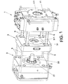
- the mold comprises a movable part (2), a fixed part (1) and an intermediate part (3).
- the fixed part (1) comprises a first plate (11) in turn comprising a first hole (111) traversing a first cavity (12).
- the intermediate part (3) comprises a third plate (31) in turn comprising a third hole (311) traversing a third cavity (32) and a fourth cavity (33).
- the movable part (2) comprises a second plate (21) having a protuberance (23), which can be partially housed in the first hole (111) and third hole (311) to define a feeding conduit (7).
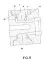
- Figure 5 shows the feeding conduit (7) which is connected to a first space and to a second space through feeding branches (9, 9'), respectively.
- the first space is defined by the first cavity (12) and the third cavity (32) corresponding with the geometry of a first piece (A), whereas the second space is defined between the fourth cavity (33) and the second cavity (22) corresponding with the geometry of a second piece (B).
- the cast aluminum is injected into these two spaces to form the pieces (A) and (B), which will be connected through the solidified aluminum in the feeding conduit (7).
- the feeding conduit (7) has to be dimensionally configured so that the cast aluminum completely fills the first and second spaces, such that the cast aluminum can solidify in the first and second spaces and inside the feeding conduit (7).
- the mold can comprise a first feeding branch (9) which is connected to the first space and a second branch (9') connected to the second space.
- the first branch (9) can also be connected to the feeding conduit (7) at a sharp angle, such that once the aluminum is injected, the first piece (A) is connected to the solidified aluminum inside the feeding conduit (7) through the solidified aluminum inside the branch (9).
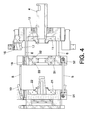
- Figure 2 shows the movable part (2), the intermediate part (3) and the fixed part (1) coupled together to cause the cast aluminum to be injected through an injection conduit (4).
- the pressure which the mold must withstand at the time of the injection is very great, therefore the mold can comprise connecting means which allow keeping the intermediate part (3), fixed part (1) and movable part (2) locked in the coupling position.
- these connecting means can comprise a locking element (16) having a boss (17) which is fitted in a housing (18) of the intermediate part (3).
- the aluminum is injected through the injection conduit (4) which can be aligned with the feeding conduit (7), such that the aluminum flows from the injection conduit (4), completely filling the first and second spaces through the feeding conduit (7).
- Figure 1 shows this demolding position, in which the parts have been separated, i.e., the movable part (2) separated with respect to the intermediate part (3) and fixed part (1), and the intermediate part (3) separated with respect to the fixed part (1).
- the movable part (2) is separated from the intermediate part (3) a first separation distance, which is a distance that is suitable so as to allow demolding the second piece (B), whereas the intermediate part (3) is separated from the fixed part (1) a second separation distance, which is the distance suitable so as to allow demolding the first piece (A).
- these pieces (A) and (B) are connected by the solidified aluminum inside the feeding conduit (7), therefore in order to demold the pieces (A) and (B), it is necessary to separate them.
- the mold can comprise fracture means configured to separate the first piece (A) from the second piece (B) and from the solidified aluminum inside the feeding conduit (7).
- the first piece (A) can be connected to the feeding conduit (7) through the feeding branch (9) which is connected, at a sharp angle, to the mentioned feeding conduit (7).
- This branch (9) has a width "n" and is configured so that when movement means, not depicted in the figures, separate the movable part (2) with respect to the intermediate part (3) and fixed part (1), the mentioned feeding branch (9) fractures due to shear stress.
- the feeding branch (9) fractures due to shear stress, being separated from the solidified aluminum inside the feeding conduit (7).
- the first piece (A) is separated from the solidified aluminum inside the feeding conduit (7), which is dragged together with the second piece.
- the demolding is carried out, what is obtained is the first piece (A) together with the solidified aluminum in the branch (9), and on the other hand, the second piece is obtained together with the solidified aluminum inside the branch (9') and the solidified aluminum inside the feeding conduit (7).
- the fracture means can comprise locking means for locking the intermediate part (3) configured to limit the movement of the mentioned part (3) at the start of the movement of the movable part (2), for the purpose of keeping the intermediate part (3) connected to the fixed part (1).
- these locking means can comprise a first step (8) arranged in a tie rod (5), a spring (13) configured to push the mentioned step (8) against the intermediate part (3) and a second step (14) arranged in the tie rod (5) which contacts with a third step (15) of the movable part (2) when the movement of the movable part (2) reaches a distance which is equivalent to the width n of the branch (9).
- coupling means In the phase for the injection of the aluminum in the first and second spaces through feeding conduit (7), coupling means, not depicted in the figures, couple the movable part (2), intermediate part (3) and fixed part (1), such that the spring (13) is compressed and the second step (14) is not in contact with the step (15) of the movable part (2).
- the movement means start to separate the movable part (2) with respect to the intermediate part (3), the spring (13) pushes the first step (8) against the intermediate part (3) so that said part (3) is connected to the fixed part (1) and, the second step (14) contacts with the third step (15) of the movable part (2).
- This movement covers a distance which is equivalent to the width "n" of the branch (9).
- the first piece (A) is already separated from the solidified aluminum inside the feeding conduit (7) and from the second piece (B).
- the movement means continue to separate the movable part (2) from the intermediate part (3) until reaching the first separation distance.
- the first separation distance is reached when a second stop (52) of the tie rod (5) contacts with the intermediate part (3).
- the second stop (52) can collide, for example, with a boss arranged in the intermediate part (3) such that the movable part (2) drags the intermediate part (3), separating it with respect to the fixed part (1).
- Figure 3 shows how the movable part (2) has reached the first separation distance.
- the pieces (A) and (B) have been separated and the piece to be demolded is a piece formed by the second piece (B) and the solidified aluminum inside the feeding conduit (7).
- the second stop (52) has collided with the boss of the intermediate part (2).
- the intermediate part (3) is dragged to be separated with respect to the fixed part (1).
- the second separation distance is reached when a third stop (61) of guides (6) collides with the intermediate part (3). This position is shown in Figure 4 . Once the second separation distance has been reached, the first piece (A) can be demolded.
Landscapes
- Engineering & Computer Science (AREA)
- Mechanical Engineering (AREA)
- Moulds For Moulding Plastics Or The Like (AREA)
Priority Applications (2)
| Application Number | Priority Date | Filing Date | Title |
|---|---|---|---|
| ES09382053.8T ES2471137T3 (es) | 2009-04-23 | 2009-04-23 | Molde de inyección de piezas de aluminio en línea |
| EP20090382053 EP2243576B1 (fr) | 2009-04-23 | 2009-04-23 | Moule à injection pour la fabrication de pièces d'aluminium en ligne |
Applications Claiming Priority (1)
| Application Number | Priority Date | Filing Date | Title |
|---|---|---|---|
| EP20090382053 EP2243576B1 (fr) | 2009-04-23 | 2009-04-23 | Moule à injection pour la fabrication de pièces d'aluminium en ligne |
Publications (2)
| Publication Number | Publication Date |
|---|---|
| EP2243576A1 true EP2243576A1 (fr) | 2010-10-27 |
| EP2243576B1 EP2243576B1 (fr) | 2014-05-21 |
Family
ID=40749853
Family Applications (1)
| Application Number | Title | Priority Date | Filing Date |
|---|---|---|---|
| EP20090382053 Active EP2243576B1 (fr) | 2009-04-23 | 2009-04-23 | Moule à injection pour la fabrication de pièces d'aluminium en ligne |
Country Status (2)
| Country | Link |
|---|---|
| EP (1) | EP2243576B1 (fr) |
| ES (1) | ES2471137T3 (fr) |
Cited By (1)
| Publication number | Priority date | Publication date | Assignee | Title |
|---|---|---|---|---|
| CN117961025A (zh) * | 2024-03-28 | 2024-05-03 | 兴化市永泰新材料有限公司 | 一种汽车零件压铸机 |
Citations (3)
| Publication number | Priority date | Publication date | Assignee | Title |
|---|---|---|---|---|
| US4589840A (en) | 1985-03-18 | 1986-05-20 | Husky Injection Molding Systems Ltd. | Apparatus and method for removing molded articles in uniform orientation |
| WO2002038311A1 (fr) | 2000-11-10 | 2002-05-16 | Idra Presse S.P.A. | Machine de coulee sous pression |
| US7320591B2 (en) | 1997-02-25 | 2008-01-22 | Jes Tougaard Gram | Procedure and machine for multi-component molding |
-
2009
- 2009-04-23 EP EP20090382053 patent/EP2243576B1/fr active Active
- 2009-04-23 ES ES09382053.8T patent/ES2471137T3/es active Active
Patent Citations (3)
| Publication number | Priority date | Publication date | Assignee | Title |
|---|---|---|---|---|
| US4589840A (en) | 1985-03-18 | 1986-05-20 | Husky Injection Molding Systems Ltd. | Apparatus and method for removing molded articles in uniform orientation |
| US7320591B2 (en) | 1997-02-25 | 2008-01-22 | Jes Tougaard Gram | Procedure and machine for multi-component molding |
| WO2002038311A1 (fr) | 2000-11-10 | 2002-05-16 | Idra Presse S.P.A. | Machine de coulee sous pression |
Cited By (2)
| Publication number | Priority date | Publication date | Assignee | Title |
|---|---|---|---|---|
| CN117961025A (zh) * | 2024-03-28 | 2024-05-03 | 兴化市永泰新材料有限公司 | 一种汽车零件压铸机 |
| CN117961025B (zh) * | 2024-03-28 | 2024-06-11 | 兴化市永泰新材料有限公司 | 一种汽车零件压铸机 |
Also Published As
| Publication number | Publication date |
|---|---|
| ES2471137T3 (es) | 2014-06-25 |
| EP2243576B1 (fr) | 2014-05-21 |
Similar Documents
| Publication | Publication Date | Title |
|---|---|---|
| CN103624233B (zh) | 压力铸造装置及压力铸造方法 | |
| JP2014042926A5 (fr) | ||
| JP5515302B2 (ja) | 金型装置及び成形品の製造方法 | |
| CN107053613A (zh) | 一种滑块二次抽芯强脱孔机构 | |
| GB2476703A (en) | Controlling the volume of injected resin in injection moulding | |
| WO2007048291A1 (fr) | Procede et dispositif de retrait et d’insertion de noyau avec ouverture et fermeture synchrone de moule | |
| EP2243576A1 (fr) | Moule à injection pour la fabrication de pièces d'aluminium en ligne | |
| CN106393592A (zh) | 一种流道可调的注塑模具 | |
| JPH067977B2 (ja) | 金型のガス抜き装置 | |
| US2808627A (en) | Die casting apparatus | |
| WO2012172669A1 (fr) | Dispositif de moulage pour le moulage par injection et machine à mouler par injection | |
| EP4091738B1 (fr) | Appareil et procédé de formage de matériau | |
| CZ436798A3 (cs) | Způsob a zařízení pro lití pod tlakem | |
| CN107921683A (zh) | 带有层压模具的用于注射冲压应用的注射成型机器以及注射冲压方法 | |
| KR101234028B1 (ko) | 복합 언더컷부 성형용 사출성형 금형 | |
| EP3445557B1 (fr) | Procédé d'utilisation d'un appareil de moulage par injection | |
| EP3797966B1 (fr) | Dispositif d'ajustage automatique de portes d'injection et procédé de fonctionnement | |
| EP2388123A1 (fr) | Procédé et appareil pour surmoulage par injection de pièces en matière métallique | |
| JP6000134B2 (ja) | モールド射出成形金型 | |
| JP2008221656A (ja) | 樹脂成形品の製造方法及び樹脂成形装置 | |
| JP6134776B1 (ja) | ダイカスト用金型 | |
| KR102826750B1 (ko) | 주조품의 제조 방법 및 주조품 제조 장치 그리고 금형 | |
| US11213981B2 (en) | Device and method for producing objects from a solidifying moulding compound with a pusher device | |
| EP2815819A1 (fr) | Alimentateur exothermique | |
| JPH08276259A (ja) | 成形装置および成形方法 |
Legal Events
| Date | Code | Title | Description |
|---|---|---|---|
| PUAI | Public reference made under article 153(3) epc to a published international application that has entered the european phase |
Free format text: ORIGINAL CODE: 0009012 |
|
| AK | Designated contracting states |
Kind code of ref document: A1 Designated state(s): AT BE BG CH CY CZ DE DK EE ES FI FR GB GR HR HU IE IS IT LI LT LU LV MC MK MT NL NO PL PT RO SE SI SK TR |
|
| 17P | Request for examination filed |
Effective date: 20110426 |
|
| 17Q | First examination report despatched |
Effective date: 20120127 |
|
| GRAP | Despatch of communication of intention to grant a patent |
Free format text: ORIGINAL CODE: EPIDOSNIGR1 |
|
| INTG | Intention to grant announced |
Effective date: 20131206 |
|
| GRAS | Grant fee paid |
Free format text: ORIGINAL CODE: EPIDOSNIGR3 |
|
| GRAA | (expected) grant |
Free format text: ORIGINAL CODE: 0009210 |
|
| AK | Designated contracting states |
Kind code of ref document: B1 Designated state(s): AT BE BG CH CY CZ DE DK EE ES FI FR GB GR HR HU IE IS IT LI LT LU LV MC MK MT NL NO PL PT RO SE SI SK TR |
|
| REG | Reference to a national code |
Ref country code: GB Ref legal event code: FG4D |
|
| REG | Reference to a national code |
Ref country code: CH Ref legal event code: EP |
|
| REG | Reference to a national code |
Ref country code: AT Ref legal event code: REF Ref document number: 669351 Country of ref document: AT Kind code of ref document: T Effective date: 20140615 |
|
| REG | Reference to a national code |
Ref country code: IE Ref legal event code: FG4D |
|
| REG | Reference to a national code |
Ref country code: ES Ref legal event code: FG2A Ref document number: 2471137 Country of ref document: ES Kind code of ref document: T3 Effective date: 20140625 |
|
| REG | Reference to a national code |
Ref country code: DE Ref legal event code: R096 Ref document number: 602009024236 Country of ref document: DE Effective date: 20140703 |
|
| REG | Reference to a national code |
Ref country code: NL Ref legal event code: VDEP Effective date: 20140521 Ref country code: AT Ref legal event code: MK05 Ref document number: 669351 Country of ref document: AT Kind code of ref document: T Effective date: 20140521 |
|
| REG | Reference to a national code |
Ref country code: LT Ref legal event code: MG4D |
|
| PG25 | Lapsed in a contracting state [announced via postgrant information from national office to epo] |
Ref country code: IS Free format text: LAPSE BECAUSE OF FAILURE TO SUBMIT A TRANSLATION OF THE DESCRIPTION OR TO PAY THE FEE WITHIN THE PRESCRIBED TIME-LIMIT Effective date: 20140921 Ref country code: FI Free format text: LAPSE BECAUSE OF FAILURE TO SUBMIT A TRANSLATION OF THE DESCRIPTION OR TO PAY THE FEE WITHIN THE PRESCRIBED TIME-LIMIT Effective date: 20140521 Ref country code: LT Free format text: LAPSE BECAUSE OF FAILURE TO SUBMIT A TRANSLATION OF THE DESCRIPTION OR TO PAY THE FEE WITHIN THE PRESCRIBED TIME-LIMIT Effective date: 20140521 Ref country code: NO Free format text: LAPSE BECAUSE OF FAILURE TO SUBMIT A TRANSLATION OF THE DESCRIPTION OR TO PAY THE FEE WITHIN THE PRESCRIBED TIME-LIMIT Effective date: 20140821 |
|
| PG25 | Lapsed in a contracting state [announced via postgrant information from national office to epo] |
Ref country code: AT Free format text: LAPSE BECAUSE OF FAILURE TO SUBMIT A TRANSLATION OF THE DESCRIPTION OR TO PAY THE FEE WITHIN THE PRESCRIBED TIME-LIMIT Effective date: 20140521 Ref country code: LV Free format text: LAPSE BECAUSE OF FAILURE TO SUBMIT A TRANSLATION OF THE DESCRIPTION OR TO PAY THE FEE WITHIN THE PRESCRIBED TIME-LIMIT Effective date: 20140521 Ref country code: HR Free format text: LAPSE BECAUSE OF FAILURE TO SUBMIT A TRANSLATION OF THE DESCRIPTION OR TO PAY THE FEE WITHIN THE PRESCRIBED TIME-LIMIT Effective date: 20140521 Ref country code: SE Free format text: LAPSE BECAUSE OF FAILURE TO SUBMIT A TRANSLATION OF THE DESCRIPTION OR TO PAY THE FEE WITHIN THE PRESCRIBED TIME-LIMIT Effective date: 20140521 Ref country code: PL Free format text: LAPSE BECAUSE OF FAILURE TO SUBMIT A TRANSLATION OF THE DESCRIPTION OR TO PAY THE FEE WITHIN THE PRESCRIBED TIME-LIMIT Effective date: 20140521 |
|
| PG25 | Lapsed in a contracting state [announced via postgrant information from national office to epo] |
Ref country code: PT Free format text: LAPSE BECAUSE OF FAILURE TO SUBMIT A TRANSLATION OF THE DESCRIPTION OR TO PAY THE FEE WITHIN THE PRESCRIBED TIME-LIMIT Effective date: 20140922 |
|
| PG25 | Lapsed in a contracting state [announced via postgrant information from national office to epo] |
Ref country code: SK Free format text: LAPSE BECAUSE OF FAILURE TO SUBMIT A TRANSLATION OF THE DESCRIPTION OR TO PAY THE FEE WITHIN THE PRESCRIBED TIME-LIMIT Effective date: 20140521 Ref country code: DK Free format text: LAPSE BECAUSE OF FAILURE TO SUBMIT A TRANSLATION OF THE DESCRIPTION OR TO PAY THE FEE WITHIN THE PRESCRIBED TIME-LIMIT Effective date: 20140521 Ref country code: RO Free format text: LAPSE BECAUSE OF FAILURE TO SUBMIT A TRANSLATION OF THE DESCRIPTION OR TO PAY THE FEE WITHIN THE PRESCRIBED TIME-LIMIT Effective date: 20140521 Ref country code: CZ Free format text: LAPSE BECAUSE OF FAILURE TO SUBMIT A TRANSLATION OF THE DESCRIPTION OR TO PAY THE FEE WITHIN THE PRESCRIBED TIME-LIMIT Effective date: 20140521 Ref country code: BE Free format text: LAPSE BECAUSE OF FAILURE TO SUBMIT A TRANSLATION OF THE DESCRIPTION OR TO PAY THE FEE WITHIN THE PRESCRIBED TIME-LIMIT Effective date: 20140521 Ref country code: EE Free format text: LAPSE BECAUSE OF FAILURE TO SUBMIT A TRANSLATION OF THE DESCRIPTION OR TO PAY THE FEE WITHIN THE PRESCRIBED TIME-LIMIT Effective date: 20140521 |
|
| REG | Reference to a national code |
Ref country code: DE Ref legal event code: R097 Ref document number: 602009024236 Country of ref document: DE |
|
| PG25 | Lapsed in a contracting state [announced via postgrant information from national office to epo] |
Ref country code: NL Free format text: LAPSE BECAUSE OF FAILURE TO SUBMIT A TRANSLATION OF THE DESCRIPTION OR TO PAY THE FEE WITHIN THE PRESCRIBED TIME-LIMIT Effective date: 20140521 |
|
| PLBE | No opposition filed within time limit |
Free format text: ORIGINAL CODE: 0009261 |
|
| STAA | Information on the status of an ep patent application or granted ep patent |
Free format text: STATUS: NO OPPOSITION FILED WITHIN TIME LIMIT |
|
| 26N | No opposition filed |
Effective date: 20150224 |
|
| REG | Reference to a national code |
Ref country code: DE Ref legal event code: R097 Ref document number: 602009024236 Country of ref document: DE Effective date: 20150224 |
|
| PG25 | Lapsed in a contracting state [announced via postgrant information from national office to epo] |
Ref country code: SI Free format text: LAPSE BECAUSE OF FAILURE TO SUBMIT A TRANSLATION OF THE DESCRIPTION OR TO PAY THE FEE WITHIN THE PRESCRIBED TIME-LIMIT Effective date: 20140521 |
|
| REG | Reference to a national code |
Ref country code: CH Ref legal event code: PLI Free format text: EXCLUSIVE LICENCE Name of requester: SIVANTOS PTE. LTD., SG |
|
| PG25 | Lapsed in a contracting state [announced via postgrant information from national office to epo] |
Ref country code: LU Free format text: LAPSE BECAUSE OF FAILURE TO SUBMIT A TRANSLATION OF THE DESCRIPTION OR TO PAY THE FEE WITHIN THE PRESCRIBED TIME-LIMIT Effective date: 20150423 Ref country code: MC Free format text: LAPSE BECAUSE OF FAILURE TO SUBMIT A TRANSLATION OF THE DESCRIPTION OR TO PAY THE FEE WITHIN THE PRESCRIBED TIME-LIMIT Effective date: 20140521 |
|
| REG | Reference to a national code |
Ref country code: CH Ref legal event code: PL |
|
| REG | Reference to a national code |
Ref country code: IE Ref legal event code: MM4A |
|
| PG25 | Lapsed in a contracting state [announced via postgrant information from national office to epo] |
Ref country code: CH Free format text: LAPSE BECAUSE OF NON-PAYMENT OF DUE FEES Effective date: 20150430 Ref country code: LI Free format text: LAPSE BECAUSE OF NON-PAYMENT OF DUE FEES Effective date: 20150430 |
|
| REG | Reference to a national code |
Ref country code: FR Ref legal event code: PLFP Year of fee payment: 8 |
|
| PG25 | Lapsed in a contracting state [announced via postgrant information from national office to epo] |
Ref country code: IE Free format text: LAPSE BECAUSE OF NON-PAYMENT OF DUE FEES Effective date: 20150423 |
|
| PG25 | Lapsed in a contracting state [announced via postgrant information from national office to epo] |
Ref country code: MT Free format text: LAPSE BECAUSE OF FAILURE TO SUBMIT A TRANSLATION OF THE DESCRIPTION OR TO PAY THE FEE WITHIN THE PRESCRIBED TIME-LIMIT Effective date: 20140521 |
|
| REG | Reference to a national code |
Ref country code: FR Ref legal event code: PLFP Year of fee payment: 9 |
|
| PG25 | Lapsed in a contracting state [announced via postgrant information from national office to epo] |
Ref country code: HU Free format text: LAPSE BECAUSE OF FAILURE TO SUBMIT A TRANSLATION OF THE DESCRIPTION OR TO PAY THE FEE WITHIN THE PRESCRIBED TIME-LIMIT; INVALID AB INITIO Effective date: 20090423 Ref country code: BG Free format text: LAPSE BECAUSE OF FAILURE TO SUBMIT A TRANSLATION OF THE DESCRIPTION OR TO PAY THE FEE WITHIN THE PRESCRIBED TIME-LIMIT Effective date: 20140521 |
|
| PG25 | Lapsed in a contracting state [announced via postgrant information from national office to epo] |
Ref country code: GR Free format text: LAPSE BECAUSE OF FAILURE TO SUBMIT A TRANSLATION OF THE DESCRIPTION OR TO PAY THE FEE WITHIN THE PRESCRIBED TIME-LIMIT Effective date: 20140521 Ref country code: CY Free format text: LAPSE BECAUSE OF FAILURE TO SUBMIT A TRANSLATION OF THE DESCRIPTION OR TO PAY THE FEE WITHIN THE PRESCRIBED TIME-LIMIT Effective date: 20140521 |
|
| PG25 | Lapsed in a contracting state [announced via postgrant information from national office to epo] |
Ref country code: TR Free format text: LAPSE BECAUSE OF FAILURE TO SUBMIT A TRANSLATION OF THE DESCRIPTION OR TO PAY THE FEE WITHIN THE PRESCRIBED TIME-LIMIT Effective date: 20140521 |
|
| REG | Reference to a national code |
Ref country code: FR Ref legal event code: PLFP Year of fee payment: 10 |
|
| PG25 | Lapsed in a contracting state [announced via postgrant information from national office to epo] |
Ref country code: MK Free format text: LAPSE BECAUSE OF FAILURE TO SUBMIT A TRANSLATION OF THE DESCRIPTION OR TO PAY THE FEE WITHIN THE PRESCRIBED TIME-LIMIT Effective date: 20140521 |
|
| PGFP | Annual fee paid to national office [announced via postgrant information from national office to epo] |
Ref country code: FR Payment date: 20250318 Year of fee payment: 17 |
|
| PGFP | Annual fee paid to national office [announced via postgrant information from national office to epo] |
Ref country code: GB Payment date: 20250313 Year of fee payment: 17 |
|
| PGFP | Annual fee paid to national office [announced via postgrant information from national office to epo] |
Ref country code: DE Payment date: 20250422 Year of fee payment: 17 |
|
| PGFP | Annual fee paid to national office [announced via postgrant information from national office to epo] |
Ref country code: ES Payment date: 20250506 Year of fee payment: 17 |
|
| PGFP | Annual fee paid to national office [announced via postgrant information from national office to epo] |
Ref country code: IT Payment date: 20250401 Year of fee payment: 17 |