EP2243581B1 - Outil manuel doté d'un entraînement d'oscillation linéaire - Google Patents
Outil manuel doté d'un entraînement d'oscillation linéaire Download PDFInfo
- Publication number
- EP2243581B1 EP2243581B1 EP10001640.1A EP10001640A EP2243581B1 EP 2243581 B1 EP2243581 B1 EP 2243581B1 EP 10001640 A EP10001640 A EP 10001640A EP 2243581 B1 EP2243581 B1 EP 2243581B1
- Authority
- EP
- European Patent Office
- Prior art keywords
- piston
- hand tool
- motor housing
- compressed air
- working chambers
- Prior art date
- Legal status (The legal status is an assumption and is not a legal conclusion. Google has not performed a legal analysis and makes no representation as to the accuracy of the status listed.)
- Not-in-force
Links
Images
Classifications
-
- B—PERFORMING OPERATIONS; TRANSPORTING
- B23—MACHINE TOOLS; METAL-WORKING NOT OTHERWISE PROVIDED FOR
- B23D—PLANING; SLOTTING; SHEARING; BROACHING; SAWING; FILING; SCRAPING; LIKE OPERATIONS FOR WORKING METAL BY REMOVING MATERIAL, NOT OTHERWISE PROVIDED FOR
- B23D51/00—Sawing machines or sawing devices working with straight blades, characterised only by constructional features of particular parts; Carrying or attaching means for tools, covered by this subclass, which are connected to a carrier at both ends
- B23D51/16—Sawing machines or sawing devices working with straight blades, characterised only by constructional features of particular parts; Carrying or attaching means for tools, covered by this subclass, which are connected to a carrier at both ends of drives or feed mechanisms for straight tools, e.g. saw blades, or bows
- B23D51/18—Sawing machines or sawing devices working with straight blades, characterised only by constructional features of particular parts; Carrying or attaching means for tools, covered by this subclass, which are connected to a carrier at both ends of drives or feed mechanisms for straight tools, e.g. saw blades, or bows actuated by fluid or gas pressure
-
- F—MECHANICAL ENGINEERING; LIGHTING; HEATING; WEAPONS; BLASTING
- F16—ENGINEERING ELEMENTS AND UNITS; GENERAL MEASURES FOR PRODUCING AND MAINTAINING EFFECTIVE FUNCTIONING OF MACHINES OR INSTALLATIONS; THERMAL INSULATION IN GENERAL
- F16J—PISTONS; CYLINDERS; SEALINGS
- F16J1/00—Pistons; Trunk pistons; Plungers
- F16J1/001—One-piece pistons
- F16J1/003—One-piece pistons with integral sealing lips
-
- F—MECHANICAL ENGINEERING; LIGHTING; HEATING; WEAPONS; BLASTING
- F16—ENGINEERING ELEMENTS AND UNITS; GENERAL MEASURES FOR PRODUCING AND MAINTAINING EFFECTIVE FUNCTIONING OF MACHINES OR INSTALLATIONS; THERMAL INSULATION IN GENERAL
- F16J—PISTONS; CYLINDERS; SEALINGS
- F16J1/00—Pistons; Trunk pistons; Plungers
- F16J1/10—Connection to driving members
- F16J1/12—Connection to driving members with piston-rods, e.g. rigid connections
Definitions
- the present invention relates to a hand tool with a pneumatically operated linear oscillating drive according to the preamble of claim 1.
- a hand tool is from the EP 1 028 826 B1 known.
- the pneumatically operated linear vibration drive of the known hand tool has a motor housing and a movable piston in the motor housing, which separates two working spaces of the motor housing from each other and having a pointing to one of the two working spaces piston skirt.
- a compressed air supply to the motor housing and a spool control a supply of compressed air to both work spaces.
- the compressed air supply is such that the piston is alternately driven in one direction and the other and thus performs an oscillating float.
- the two working chambers are each vented.
- the piston drives an oscillating tool via a piston rod, for example a saw blade or a filing tool.
- a piston rod for example a saw blade or a filing tool.
- the piston crown is thin-walled and cambered and merges at its periphery into a thin-walled cylindrical sleeve in order to keep the mass of the piston and thus also the reaction forces to be eliminated in its oscillating motion low.
- Such a thin-walled cylindrical sleeve is also referred to in the present application as a piston skirt.
- the piston skirt forming the cylindrical sleeve and the piston head form a piston pot, the inside of which faces one of the two working spaces. In other words, a section taken in the direction of movement of the piston through the center of the piston results in a U-shaped cross section, wherein the two U-legs point to one of the working spaces.
- Double piston with expandable piston shirts or sealing lips are from the publications US 3,745,890 A . US 3,902,405 A . FR 2 635 365 A1 . EP 0 284 772 A2 . US 3,150,570 A and BE 509 458 A for various pneumatic and hydraulic applications such as hydraulic rams, compressed air cylinders in the food industry, and applications suitable for dry running, known for applications in connection with expandable cylinder walls in aircraft actuators.
- the object of the invention in the specification of a hand tool with a pneumatic linear vibration drive with improved efficiency. This object is achieved in a hand tool of the type mentioned with the features of claim 1.
- the invention is based on the finding that the thin-walled piston skirt radially expands under the action of the compressed air, which leads to an improved sealing of the annular gap between the piston and the engine housing.
- the better the seal the greater the pressure difference between the two working spaces and thus the resulting force.
- the improved sealing is achieved both in a forward movement and in a backward movement of the piston.
- the same force is generated in particular in both directions of movement of the piston rod.
- the piston diameter can not only expand in the region of the piston pot opening, but also in the area of the piston crown, the seal is additionally improved. Further advantages will be apparent from the dependent claims, the description and the attached figures.
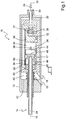
- FIG. 1 a hand tool 10 having a handle body 12 and a piston rod 14 which is movably mounted along an axis 16 in the handle body 12.
- the piston rod 14 is rigidly connected to a piston 17 which is movably mounted in a motor housing 18 within the handle body 12 in the direction of the axis 16 and a first working space 20 of a second working chamber 22 of the motor housing 18 is movably separated from each other.
- a piston 17 which is movably mounted in a motor housing 18 within the handle body 12 in the direction of the axis 16 and a first working space 20 of a second working chamber 22 of the motor housing 18 is movably separated from each other.
- Each of the two working spaces 20, 22 is viewed alternately filled with compressed air and vented, the filling of both working spaces 20, 22 takes place in each case in alternation.
- the hand tool 10 has a compressed air connection 26 with a compressed air control valve 28, with which a stream of compressed air in the working chambers 20, 22 is controllable.
- the compressed air control valve 28 is actuated by an actuating means, not shown, of the hand tool 10, as for example in the EP 1 028 826 is disclosed in the form of a manually operated toggle lever.
- the compressed air enters via the compressed air connection 26 of the hand tool 10 and a compressed air connector 30 of the motor housing 18 in the motor housing 18 and flows depending on the position of a spool 36 either via a first compressed air channel 32 in the first working space 20 or via a second compressed air duct 34 in the second Working space 22.
- the compressed air flows via the first compressed air passage 32 into the first working space 20 and drives the piston 17 to the left.
- the piston 17 passes through an exhaust port 38 in the motor housing 18, which represents an exhaust air cross-section to the outside space outside of the hand tool 10.
- the piston 17 running to the left just opens an exhaust air cross-section to the exhaust air opening 38.
- the compressed air volume flow in the first working chamber 20 increases.
- the pressure conditions on the spool 36 change so that it is pulled to the left and thereby closes the flow cross-section to the first working chamber 20 and opens a flow cross-section to the second working chamber 22 via the annular groove 37 in the spool 36.
- the then flowing into the second working chamber 22 compressed air drives the piston 17 then to the right.
- the piston 17 running to the right then opens an exhaust air cross section from the second working space to the exhaust opening 38, whereupon the spool valve 36 again switches over to a filling of the first working space 20.
- the hand tool 10 is characterized in that the piston 17 has both a first piston skirt 44 facing the first working chamber 20 and a second piston skirt 46 facing the second working chamber 22.
- the respective thin-walled piston skirt 44, 46 When filling the respective working space 20, 22 with compressed air, the respective thin-walled piston skirt 44, 46 expands in the radial direction and thus snugly fits against the inner wall of the motor housing 18, which forms a running and sealing surface for the piston 17. This nestling narrows the annular gap between the piston 17 and the motor housing 18 and thus leads to an improved seal between the two working spaces. This reduces the amount of compressed air flowing between the piston 17 and the motor housing 18 from the ventilated to the vented working space. As a result, the pressure gradient between the working spaces 20, 22 and the Air losses fall. Because of the larger pressure gradient results in a greater value of the resulting pressure force, which is available as a driving force on the tool.
- the improved sealing effect always occurs when the working chamber 20, 22 facing the respective piston skirt 44, 46 is filled with compressed air.
- the pneumatic linear oscillating drive according to the invention in addition to the first piston skirt 44, which faces the first working space 20, the second piston skirt 46, which faces the second working space 22.
- the improved sealing effect is achieved both in the outward and in the reciprocation of the piston 17.
- An efficiency-reducing flow of air between the piston 17 and the motor housing 18 during the filling of the second working space 22 with compressed air therefore occurs in the invention to a lesser extent than in the prior art.
- a preferred embodiment is characterized in that a material cross section of the piston skirt 44, 46 is smaller than a material cross section of a bottom 48, 49 of the piston 17.
- piston shirts 44, 46 with respect to their material and their dimensions to the operating pressure of a compressed air supply of the hand tool 10 adapted that the piston shirts 44, 46 elastically expand under the influence of compressed air.
- the piston 17 and the motor housing 18 made of metallic materials. As a result, a long service life and a high compressive strength and thus performance of the hand tool 10 is achieved.
- a further preferred embodiment is characterized in that a running surface of the piston 17 and / or the motor housing 18 is coated with a friction-reducing material, or that friction-reducing material is embedded in a metallic material of the running surface of the piston 17 and / or the motor housing 18.
- the metallic materials have light metal or consist of light metal, in particular of aluminum, because thereby the mass forces during operation of the hand tool 10 remain limited to correspondingly low values.
- a further preferred embodiment is characterized in that the running surfaces are heartkoatiert.
- the motor housing and / or the piston are made of steel.
- the design of the piston made of steel is less expensive to manufacture, because the important for the elasticity thin material cross section of the piston shirts made of steel can be relatively easily and inexpensively.
- a hardened surface is favorable for reducing wear.
- the motor housing 18 is mounted elastically movable in a handle body 12 of the hand tool 10 in the direction of movement of the piston 17.
- This type of storage allows an antiphase to the vibration of the piston 17 taking place vibration of the motor housing 18, which contributes to a desired eradication of inertial forces.
- the compressed air connection 26 of the hand tool 10 has a section 50 which is configured as a guide for a pressure connection piece 30 of the motor housing 18 and in which the pressure connection piece 30 is mounted in an axially movable manner.
- Each piston skirt 44, 46 forms with the associated piston crown a piston pot 54, 56, so that the piston 17 has a total of two piston heads 54, 56 which are rigidly connected to each other and open to opposite sides.
- Each piston pot 54, 56 has a cylindrical jacket in the form of its piston skirt 44, 46, a pot bottom 48, 49 and a cup opening 48, 49 opposite pot opening.
- the pot bottoms 48, 49 of both piston heads 54, 56 are at a fixed distance from each other and are arranged between the pot openings, so that the piston heads 54, 56 open in opposite directions.
- the linear oscillating drive each has an end position damping for the piston 17.
- this end position damping results in each case in that the motor housing 18 at the end of a working space 20, 22 which is opposite to the piston 17, in each case an annular groove 58, 60 which has a receptacle for the cylinder jacket-shaped piston skirt 44, 46 forms.
- the compressed air channels 32, 34 each end in the annular groove 58, 60.
- the second piston skirt 46 runs into the groove 60 and blocks the compressed air duct 34. Thereby, an air volume is trapped by the left end of the motor housing 18 in the second piston pot 56.
- the piston 17, which continues to the left compresses this volume of air and thus generates a brake on the piston, which brakes the further approach to a possible mechanical end position 17 acting damping force.
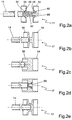
- Fig. 2 a shows an inventive embodiment of a double piston 17, which consists of two via a spacer 62 and piston pressure plates 64, 66 by means of a screw 68 with a piston rod 14 bolted piston cups 54, 56 composed. Due to the convex and thin-walled design of the piston crowns, these have an elastically variable diameter. This embodiment is characterized in that the piston diameter can not only expand in the region of the piston pot opening, but also in the region of the piston crown, which additionally improves the seal.
- Fig. 2b shows an integral alternative of a double piston 17, in which the piston heads 54, 56 are made together with the piston rod 14 of solid material.
- FIG. 2c also shows an integral alternative of a double piston 17, in which the piston heads 54, 56 are made together with the piston rod 14 of solid material.
- This embodiment is more massive than the embodiment according to the overall Fig. 2b , Another difference is that the space between the two piston bottoms is filled with solid material, which increases the inertial mass of the double piston.
- the more massive design allows a waiver of piston thrust washers when the double piston is to be bolted to the piston rod 14. This is done by the Fig. 2d illustrated.
- Fig. 2e shows an embodiment of a piston connected to the piston rod 14 double piston 17, wherein the compound alternatively by a screw, a bond, a combination of a screw and a bond, or by a press connection. For reasons of strength, an embodiment of the double piston made of steel is preferred for the press connection.
Landscapes
- Engineering & Computer Science (AREA)
- General Engineering & Computer Science (AREA)
- Mechanical Engineering (AREA)
- Chemical & Material Sciences (AREA)
- Combustion & Propulsion (AREA)
- Sawing (AREA)
- Actuator (AREA)
- Portable Power Tools In General (AREA)
- Pistons, Piston Rings, And Cylinders (AREA)
Claims (8)
- Outil à main (10) comportant un entraînement oscillant linéaire à commande pneumatique présentant un carter de moteur (18) et un piston (17) mobile dans le carter de moteur (18), lequel piston sépare deux espaces de travail (20, 22) du carter de moteur (18) et présente une chemise de piston (44) dirigée vers l'un (20) des deux espaces de travail (20, 22), une conduite d'alimentation en air comprimé vers le carter de moteur (18) et une coulisse de commande (36) qui commande une alimentation en air comprimé alternativement vers l'un et l'autre des deux espaces de travail (20, 22), et un orifice d'évacuation d'air (38) dans le carter de moteur (18), le piston (17) et le carter de moteur (18) étant constitués de matières métalliques, et une surface de roulement du piston (17) et/ou du carter de moteur (18) étant revêtue d'une matière réduisant les frottements, ou une matière réduisant les frottements étant incorporée dans une matière métallique de la surface de roulement du piston (17) et/ou du carter de moteur (18), caractérisé en ce que le piston (17) présente, en plus, une chemise de piston (46) dirigée vers l'autre (20) des deux espaces de travail (20, 22), les chemises de piston (44, 46) étant adaptées, au niveau de leur matière et de leurs dimensions, à la pression de service d'une alimentation en air comprimé de l'outil à main (10) de telle manière que les chemises de piston (44, 46) s'élargissent de manière élastique sous l'action de l'air comprimé et les deux têtes (48, 49) du piston (17), dirigées vers les deux espaces de travail (20, 22) sont convexes et ont des parois minces de manière à présenter un diamètre variable de manière élastique de sorte que le diamètre du piston ne se dilate pas seulement au niveau d'une ouverture de piston mais aussi, en plus, au niveau de la tête de piston.
- Outil à main (10) selon la revendication 1, caractérisé en ce qu'une section de la matière des chemises de piston (44, 46) est inférieure à celle d'une tête (48, 49) du piston (17) .
- Outil à main (10) selon la revendication 1, caractérisé en ce que les matières métalliques présentent un métal léger ou sont constituées d'un métal léger.
- Outil à main (10) selon la revendication 1, caractérisé en ce que le métal léger est de l'aluminium.
- Outil à main (10) selon l'une quelconque des revendications 3 à 4, caractérisé en ce que la surface de roulement a un revêtement dur.
- Outil à main (10) selon la revendication 1, caractérisé en ce que la matière métallique est de l'acier.
- Outil à main (10) selon la revendication 6, caractérisé par une surface trempée.
- Outil à main (10) selon l'une quelconque des revendications précédentes, caractérisé en ce que le carter de moteur (18) est positionné de manière mobile et élastique dans un organe de préhension (12) de l'outil à main (10) dans le sens de déplacement du piston (17).
Applications Claiming Priority (1)
| Application Number | Priority Date | Filing Date | Title |
|---|---|---|---|
| DE102009019081A DE102009019081A1 (de) | 2009-04-22 | 2009-04-22 | Handwerkzeug mit einem Linear-Schwingantrieb |
Publications (2)
| Publication Number | Publication Date |
|---|---|
| EP2243581A1 EP2243581A1 (fr) | 2010-10-27 |
| EP2243581B1 true EP2243581B1 (fr) | 2017-10-18 |
Family
ID=42542837
Family Applications (1)
| Application Number | Title | Priority Date | Filing Date |
|---|---|---|---|
| EP10001640.1A Not-in-force EP2243581B1 (fr) | 2009-04-22 | 2010-02-18 | Outil manuel doté d'un entraînement d'oscillation linéaire |
Country Status (8)
| Country | Link |
|---|---|
| US (1) | US8292003B2 (fr) |
| EP (1) | EP2243581B1 (fr) |
| JP (1) | JP5276621B2 (fr) |
| CN (1) | CN101885176B (fr) |
| DE (1) | DE102009019081A1 (fr) |
| DK (1) | DK2243581T3 (fr) |
| ES (1) | ES2654536T3 (fr) |
| TW (1) | TWI481483B (fr) |
Families Citing this family (9)
| Publication number | Priority date | Publication date | Assignee | Title |
|---|---|---|---|---|
| CN102275013B (zh) * | 2011-08-15 | 2013-04-03 | 成都飞机工业(集团)有限责任公司 | 气动往复锯 |
| CH706211B1 (de) * | 2012-03-08 | 2016-03-31 | Suhner Intertrade Ag | Mit Druckluft betriebene Antriebsmaschine für eine oszillierende Säge oder Feile. |
| KR101412092B1 (ko) * | 2013-11-28 | 2014-07-02 | 주식회사 엔와이테크 | 저소음형 유압 타격 장치 |
| TWM513773U (zh) * | 2015-06-24 | 2015-12-11 | Basso Ind Corp | 氣動鋸之具有緩衝效果的氣動裝置 |
| DE102016112616B3 (de) | 2016-07-08 | 2017-12-14 | Biax Maschinen Gmbh | Rippenschälgerät mit einem ausbalancierten Klingenhalter |
| EP3743241A4 (fr) | 2018-01-23 | 2021-11-10 | Quantum Impact, LLC | Procédé et appareil d'usinage d'une pièce |
| JP2020037432A (ja) * | 2018-09-04 | 2020-03-12 | 矢崎総業株式会社 | バンド結束工具 |
| CN112128372A (zh) * | 2020-10-16 | 2020-12-25 | 苏州舍勒智能科技有限公司 | 一种用于推杆缸活塞与活塞杆连接结构 |
| CN114669781B (zh) * | 2022-04-21 | 2024-01-30 | 深圳市速航科技发展有限公司 | 一种活塞轴可旋转的气动振动装置 |
Family Cites Families (16)
| Publication number | Priority date | Publication date | Assignee | Title |
|---|---|---|---|---|
| BE509458A (fr) * | ||||
| DE314231C (fr) * | ||||
| DE316135C (fr) * | ||||
| DE288325C (fr) * | 1913-11-22 | |||
| US3150570A (en) * | 1963-05-14 | 1964-09-29 | American Mach & Foundry | Piston |
| US3745890A (en) * | 1971-06-09 | 1973-07-17 | N Costarella | Ringless piston |
| US3902405A (en) * | 1971-06-09 | 1975-09-02 | Nino F Costarella | Ringless piston |
| JPS6190883A (ja) * | 1984-10-12 | 1986-05-09 | 日東工器株式会社 | 空圧式衝撃工具等の緩衝装置 |
| DE3710403A1 (de) * | 1987-03-28 | 1988-10-06 | Lechler Elring Dichtungswerke | Komplettkolben |
| DE3826931A1 (de) * | 1988-08-09 | 1990-02-22 | Kaco Gmbh Co | Kolbendichtung |
| JP3378029B2 (ja) * | 1991-08-08 | 2003-02-17 | 丸善工業株式会社 | 油圧ブレーカ |
| US5626199A (en) * | 1995-07-05 | 1997-05-06 | T.C. Service Company | Pneumatic impact tool having improved vibration and noise attenuation |
| JPH09144884A (ja) * | 1995-11-24 | 1997-06-03 | Nok Corp | ピストン |
| DE19746447C2 (de) | 1997-10-21 | 2002-11-07 | Biax Maschinen Gmbh Steckborn | Handwerkzeug mit einem Linear-Schwingantrieb |
| ATE467487T1 (de) * | 2003-03-21 | 2010-05-15 | Black & Decker Inc | Schwingungsreduziervorrichtung für kraftbetriebenes werkzeug und solch eine vorrichtung enthaltendes kraftbetriebenes werkzeug |
| TWM351754U (en) * | 2008-10-22 | 2009-03-01 | Hong Bing Pneumatic Industry Co Ltd | Rotary type power tool structure |
-
2009
- 2009-04-22 DE DE102009019081A patent/DE102009019081A1/de not_active Ceased
-
2010
- 2010-02-18 DK DK10001640.1T patent/DK2243581T3/da active
- 2010-02-18 ES ES10001640.1T patent/ES2654536T3/es active Active
- 2010-02-18 EP EP10001640.1A patent/EP2243581B1/fr not_active Not-in-force
- 2010-02-24 TW TW099105287A patent/TWI481483B/zh not_active IP Right Cessation
- 2010-04-13 JP JP2010092128A patent/JP5276621B2/ja not_active Expired - Fee Related
- 2010-04-21 US US12/764,378 patent/US8292003B2/en active Active
- 2010-04-22 CN CN201010167637.1A patent/CN101885176B/zh not_active Expired - Fee Related
Non-Patent Citations (1)
| Title |
|---|
| None * |
Also Published As
| Publication number | Publication date |
|---|---|
| JP5276621B2 (ja) | 2013-08-28 |
| US8292003B2 (en) | 2012-10-23 |
| EP2243581A1 (fr) | 2010-10-27 |
| JP2010253672A (ja) | 2010-11-11 |
| DK2243581T3 (da) | 2017-12-18 |
| US20100270049A1 (en) | 2010-10-28 |
| TWI481483B (zh) | 2015-04-21 |
| ES2654536T3 (es) | 2018-02-14 |
| DE102009019081A1 (de) | 2010-11-11 |
| CN101885176B (zh) | 2014-09-24 |
| TW201039988A (en) | 2010-11-16 |
| CN101885176A (zh) | 2010-11-17 |
Similar Documents
| Publication | Publication Date | Title |
|---|---|---|
| EP2243581B1 (fr) | Outil manuel doté d'un entraînement d'oscillation linéaire | |
| DE3852260T2 (de) | Pumpe und Ventil. | |
| DE2008684C3 (de) | Steuerung für einen doppelt wirken den Pneumatik Kolbenmotor | |
| EP3183149B1 (fr) | Groupe motopompe à moteur électrique | |
| DE19603109C2 (de) | Kolben-Kältemittelkompressor mit verbesserter Dichtfunktion | |
| DE3934124A1 (de) | Druckluftgetriebene pumpenanordnung | |
| DE60215467T2 (de) | Kolbenschmiersystem für einen hubkolbenverdichter mit einem linearmotor | |
| EP2163784A2 (fr) | Amortisseur d'oscillations doté d'une force d'amortissement à amplitude sélective | |
| DE4015786A1 (de) | Kolbenbetriebene hydraulikpumpe | |
| DE10026147C2 (de) | Elektrohydraulisches Betätigungsgerät | |
| EP1306574A3 (fr) | Amortisseur de vibrations avec force d'amortissement réglable | |
| DE102019133576B3 (de) | Kompressor und Verfahren zur Förderung und Verdichtung eines Förderfluids in ein Zielsystem | |
| DE3542926C2 (fr) | ||
| DE10038734C2 (de) | Gedämpfter Pneumatikzylinder zur Erzeugung einer konstanten langsamen linearen Antriebsbewegung | |
| DE69420713T2 (de) | Durch druckmittel angetriebene vorrichtung die eine lineare bewegung ausführt | |
| EP0933169A2 (fr) | Dispositif de percussion actionné par un fluide | |
| WO2017178249A2 (fr) | Vérin hydraulique | |
| DE102008054976A1 (de) | Kolben für eine Schlageinheit, insbesondere eines Bohr- und/oder Schlaghammers, Elektrohandwerkzeug mit einer Schlageinheit sowie Verfahren zum Betreiben eines Elektrohandwerkzeugs | |
| EP0554760A1 (fr) | Multiplication de pression hydropneumatique | |
| DE102011106545A1 (de) | Vorrichtung Kolbenabstützung an Hubkolbenmaschinen | |
| DE3717546A1 (de) | Bremsbetaetigungsvorrichtung fuer kraftfahrzeuge | |
| DE10253020A1 (de) | Pneumatische Betätigungseinrichtung, insbesondere für eine Reibungskupplung | |
| DE2246571A1 (de) | Vibrator | |
| DE4233149C1 (de) | Druckluftmotor | |
| DE1209520B (de) | Motorisch angetriebener Hammer |
Legal Events
| Date | Code | Title | Description |
|---|---|---|---|
| PUAI | Public reference made under article 153(3) epc to a published international application that has entered the european phase |
Free format text: ORIGINAL CODE: 0009012 |
|
| AK | Designated contracting states |
Kind code of ref document: A1 Designated state(s): AT BE BG CH CY CZ DE DK EE ES FI FR GB GR HR HU IE IS IT LI LT LU LV MC MK MT NL NO PL PT RO SE SI SK SM TR |
|
| AX | Request for extension of the european patent |
Extension state: AL BA RS |
|
| 17P | Request for examination filed |
Effective date: 20110426 |
|
| 17Q | First examination report despatched |
Effective date: 20130603 |
|
| RIN1 | Information on inventor provided before grant (corrected) |
Inventor name: BAUMANN, MARCO |
|
| GRAP | Despatch of communication of intention to grant a patent |
Free format text: ORIGINAL CODE: EPIDOSNIGR1 |
|
| INTG | Intention to grant announced |
Effective date: 20170510 |
|
| GRAS | Grant fee paid |
Free format text: ORIGINAL CODE: EPIDOSNIGR3 |
|
| GRAA | (expected) grant |
Free format text: ORIGINAL CODE: 0009210 |
|
| STAA | Information on the status of an ep patent application or granted ep patent |
Free format text: STATUS: THE PATENT HAS BEEN GRANTED |
|
| RAP1 | Party data changed (applicant data changed or rights of an application transferred) |
Owner name: BIAX MASCHINEN GMBH |
|
| AK | Designated contracting states |
Kind code of ref document: B1 Designated state(s): AT BE BG CH CY CZ DE DK EE ES FI FR GB GR HR HU IE IS IT LI LT LU LV MC MK MT NL NO PL PT RO SE SI SK SM TR |
|
| REG | Reference to a national code |
Ref country code: GB Ref legal event code: FG4D Free format text: NOT ENGLISH |
|
| REG | Reference to a national code |
Ref country code: CH Ref legal event code: EP |
|
| REG | Reference to a national code |
Ref country code: CH Ref legal event code: NV Representative=s name: DREISS PATENTANWAELTE PARTG MBB, DE Ref country code: AT Ref legal event code: REF Ref document number: 937507 Country of ref document: AT Kind code of ref document: T Effective date: 20171115 Ref country code: IE Ref legal event code: FG4D Free format text: LANGUAGE OF EP DOCUMENT: GERMAN |
|
| REG | Reference to a national code |
Ref country code: DE Ref legal event code: R096 Ref document number: 502010014259 Country of ref document: DE |
|
| REG | Reference to a national code |
Ref country code: DK Ref legal event code: T3 Effective date: 20171213 |
|
| REG | Reference to a national code |
Ref country code: ES Ref legal event code: FG2A Ref document number: 2654536 Country of ref document: ES Kind code of ref document: T3 Effective date: 20180214 |
|
| REG | Reference to a national code |
Ref country code: NL Ref legal event code: MP Effective date: 20171018 |
|
| REG | Reference to a national code |
Ref country code: LT Ref legal event code: MG4D |
|
| PG25 | Lapsed in a contracting state [announced via postgrant information from national office to epo] |
Ref country code: NL Free format text: LAPSE BECAUSE OF FAILURE TO SUBMIT A TRANSLATION OF THE DESCRIPTION OR TO PAY THE FEE WITHIN THE PRESCRIBED TIME-LIMIT Effective date: 20171018 |
|
| PG25 | Lapsed in a contracting state [announced via postgrant information from national office to epo] |
Ref country code: SE Free format text: LAPSE BECAUSE OF FAILURE TO SUBMIT A TRANSLATION OF THE DESCRIPTION OR TO PAY THE FEE WITHIN THE PRESCRIBED TIME-LIMIT Effective date: 20171018 Ref country code: LT Free format text: LAPSE BECAUSE OF FAILURE TO SUBMIT A TRANSLATION OF THE DESCRIPTION OR TO PAY THE FEE WITHIN THE PRESCRIBED TIME-LIMIT Effective date: 20171018 Ref country code: NO Free format text: LAPSE BECAUSE OF FAILURE TO SUBMIT A TRANSLATION OF THE DESCRIPTION OR TO PAY THE FEE WITHIN THE PRESCRIBED TIME-LIMIT Effective date: 20180118 Ref country code: FI Free format text: LAPSE BECAUSE OF FAILURE TO SUBMIT A TRANSLATION OF THE DESCRIPTION OR TO PAY THE FEE WITHIN THE PRESCRIBED TIME-LIMIT Effective date: 20171018 |
|
| PG25 | Lapsed in a contracting state [announced via postgrant information from national office to epo] |
Ref country code: LV Free format text: LAPSE BECAUSE OF FAILURE TO SUBMIT A TRANSLATION OF THE DESCRIPTION OR TO PAY THE FEE WITHIN THE PRESCRIBED TIME-LIMIT Effective date: 20171018 Ref country code: BG Free format text: LAPSE BECAUSE OF FAILURE TO SUBMIT A TRANSLATION OF THE DESCRIPTION OR TO PAY THE FEE WITHIN THE PRESCRIBED TIME-LIMIT Effective date: 20180118 Ref country code: GR Free format text: LAPSE BECAUSE OF FAILURE TO SUBMIT A TRANSLATION OF THE DESCRIPTION OR TO PAY THE FEE WITHIN THE PRESCRIBED TIME-LIMIT Effective date: 20180119 Ref country code: IS Free format text: LAPSE BECAUSE OF FAILURE TO SUBMIT A TRANSLATION OF THE DESCRIPTION OR TO PAY THE FEE WITHIN THE PRESCRIBED TIME-LIMIT Effective date: 20180218 Ref country code: HR Free format text: LAPSE BECAUSE OF FAILURE TO SUBMIT A TRANSLATION OF THE DESCRIPTION OR TO PAY THE FEE WITHIN THE PRESCRIBED TIME-LIMIT Effective date: 20171018 |
|
| REG | Reference to a national code |
Ref country code: DE Ref legal event code: R097 Ref document number: 502010014259 Country of ref document: DE |
|
| PG25 | Lapsed in a contracting state [announced via postgrant information from national office to epo] |
Ref country code: EE Free format text: LAPSE BECAUSE OF FAILURE TO SUBMIT A TRANSLATION OF THE DESCRIPTION OR TO PAY THE FEE WITHIN THE PRESCRIBED TIME-LIMIT Effective date: 20171018 Ref country code: SK Free format text: LAPSE BECAUSE OF FAILURE TO SUBMIT A TRANSLATION OF THE DESCRIPTION OR TO PAY THE FEE WITHIN THE PRESCRIBED TIME-LIMIT Effective date: 20171018 |
|
| PLBE | No opposition filed within time limit |
Free format text: ORIGINAL CODE: 0009261 |
|
| STAA | Information on the status of an ep patent application or granted ep patent |
Free format text: STATUS: NO OPPOSITION FILED WITHIN TIME LIMIT |
|
| PG25 | Lapsed in a contracting state [announced via postgrant information from national office to epo] |
Ref country code: RO Free format text: LAPSE BECAUSE OF FAILURE TO SUBMIT A TRANSLATION OF THE DESCRIPTION OR TO PAY THE FEE WITHIN THE PRESCRIBED TIME-LIMIT Effective date: 20171018 Ref country code: SM Free format text: LAPSE BECAUSE OF FAILURE TO SUBMIT A TRANSLATION OF THE DESCRIPTION OR TO PAY THE FEE WITHIN THE PRESCRIBED TIME-LIMIT Effective date: 20171018 Ref country code: PL Free format text: LAPSE BECAUSE OF FAILURE TO SUBMIT A TRANSLATION OF THE DESCRIPTION OR TO PAY THE FEE WITHIN THE PRESCRIBED TIME-LIMIT Effective date: 20171018 |
|
| 26N | No opposition filed |
Effective date: 20180719 |
|
| PG25 | Lapsed in a contracting state [announced via postgrant information from national office to epo] |
Ref country code: MC Free format text: LAPSE BECAUSE OF FAILURE TO SUBMIT A TRANSLATION OF THE DESCRIPTION OR TO PAY THE FEE WITHIN THE PRESCRIBED TIME-LIMIT Effective date: 20171018 Ref country code: MT Free format text: LAPSE BECAUSE OF FAILURE TO SUBMIT A TRANSLATION OF THE DESCRIPTION OR TO PAY THE FEE WITHIN THE PRESCRIBED TIME-LIMIT Effective date: 20171018 |
|
| GBPC | Gb: european patent ceased through non-payment of renewal fee |
Effective date: 20180218 |
|
| REG | Reference to a national code |
Ref country code: IE Ref legal event code: MM4A |
|
| PG25 | Lapsed in a contracting state [announced via postgrant information from national office to epo] |
Ref country code: SI Free format text: LAPSE BECAUSE OF FAILURE TO SUBMIT A TRANSLATION OF THE DESCRIPTION OR TO PAY THE FEE WITHIN THE PRESCRIBED TIME-LIMIT Effective date: 20171018 Ref country code: LU Free format text: LAPSE BECAUSE OF NON-PAYMENT OF DUE FEES Effective date: 20180218 |
|
| REG | Reference to a national code |
Ref country code: FR Ref legal event code: ST Effective date: 20181031 |
|
| PG25 | Lapsed in a contracting state [announced via postgrant information from national office to epo] |
Ref country code: IE Free format text: LAPSE BECAUSE OF NON-PAYMENT OF DUE FEES Effective date: 20180218 |
|
| PG25 | Lapsed in a contracting state [announced via postgrant information from national office to epo] |
Ref country code: GB Free format text: LAPSE BECAUSE OF NON-PAYMENT OF DUE FEES Effective date: 20180218 Ref country code: FR Free format text: LAPSE BECAUSE OF NON-PAYMENT OF DUE FEES Effective date: 20180228 |
|
| PG25 | Lapsed in a contracting state [announced via postgrant information from national office to epo] |
Ref country code: TR Free format text: LAPSE BECAUSE OF FAILURE TO SUBMIT A TRANSLATION OF THE DESCRIPTION OR TO PAY THE FEE WITHIN THE PRESCRIBED TIME-LIMIT Effective date: 20171018 |
|
| PG25 | Lapsed in a contracting state [announced via postgrant information from national office to epo] |
Ref country code: PT Free format text: LAPSE BECAUSE OF FAILURE TO SUBMIT A TRANSLATION OF THE DESCRIPTION OR TO PAY THE FEE WITHIN THE PRESCRIBED TIME-LIMIT Effective date: 20171018 Ref country code: HU Free format text: LAPSE BECAUSE OF FAILURE TO SUBMIT A TRANSLATION OF THE DESCRIPTION OR TO PAY THE FEE WITHIN THE PRESCRIBED TIME-LIMIT; INVALID AB INITIO Effective date: 20100218 |
|
| PGFP | Annual fee paid to national office [announced via postgrant information from national office to epo] |
Ref country code: CZ Payment date: 20200206 Year of fee payment: 11 Ref country code: BE Payment date: 20200220 Year of fee payment: 11 |
|
| PG25 | Lapsed in a contracting state [announced via postgrant information from national office to epo] |
Ref country code: MK Free format text: LAPSE BECAUSE OF NON-PAYMENT OF DUE FEES Effective date: 20171018 Ref country code: CY Free format text: LAPSE BECAUSE OF FAILURE TO SUBMIT A TRANSLATION OF THE DESCRIPTION OR TO PAY THE FEE WITHIN THE PRESCRIBED TIME-LIMIT Effective date: 20171018 |
|
| PGFP | Annual fee paid to national office [announced via postgrant information from national office to epo] |
Ref country code: IT Payment date: 20210226 Year of fee payment: 12 Ref country code: CH Payment date: 20210222 Year of fee payment: 12 |
|
| PGFP | Annual fee paid to national office [announced via postgrant information from national office to epo] |
Ref country code: ES Payment date: 20210323 Year of fee payment: 12 Ref country code: AT Payment date: 20210216 Year of fee payment: 12 Ref country code: DK Payment date: 20210218 Year of fee payment: 12 |
|
| PGFP | Annual fee paid to national office [announced via postgrant information from national office to epo] |
Ref country code: DE Payment date: 20210419 Year of fee payment: 12 |
|
| REG | Reference to a national code |
Ref country code: BE Ref legal event code: MM Effective date: 20210228 |
|
| PG25 | Lapsed in a contracting state [announced via postgrant information from national office to epo] |
Ref country code: CZ Free format text: LAPSE BECAUSE OF NON-PAYMENT OF DUE FEES Effective date: 20210218 |
|
| PG25 | Lapsed in a contracting state [announced via postgrant information from national office to epo] |
Ref country code: BE Free format text: LAPSE BECAUSE OF NON-PAYMENT OF DUE FEES Effective date: 20210228 |
|
| REG | Reference to a national code |
Ref country code: DE Ref legal event code: R119 Ref document number: 502010014259 Country of ref document: DE |
|
| REG | Reference to a national code |
Ref country code: DK Ref legal event code: EBP Effective date: 20220228 |
|
| REG | Reference to a national code |
Ref country code: CH Ref legal event code: PL |
|
| REG | Reference to a national code |
Ref country code: AT Ref legal event code: MM01 Ref document number: 937507 Country of ref document: AT Kind code of ref document: T Effective date: 20220218 |
|
| PG25 | Lapsed in a contracting state [announced via postgrant information from national office to epo] |
Ref country code: AT Free format text: LAPSE BECAUSE OF NON-PAYMENT OF DUE FEES Effective date: 20220218 |
|
| PG25 | Lapsed in a contracting state [announced via postgrant information from national office to epo] |
Ref country code: LI Free format text: LAPSE BECAUSE OF NON-PAYMENT OF DUE FEES Effective date: 20220228 Ref country code: DK Free format text: LAPSE BECAUSE OF NON-PAYMENT OF DUE FEES Effective date: 20220228 Ref country code: DE Free format text: LAPSE BECAUSE OF NON-PAYMENT OF DUE FEES Effective date: 20220901 Ref country code: CH Free format text: LAPSE BECAUSE OF NON-PAYMENT OF DUE FEES Effective date: 20220228 |
|
| REG | Reference to a national code |
Ref country code: ES Ref legal event code: FD2A Effective date: 20230503 |
|
| PG25 | Lapsed in a contracting state [announced via postgrant information from national office to epo] |
Ref country code: IT Free format text: LAPSE BECAUSE OF NON-PAYMENT OF DUE FEES Effective date: 20220218 |
|
| PG25 | Lapsed in a contracting state [announced via postgrant information from national office to epo] |
Ref country code: ES Free format text: LAPSE BECAUSE OF NON-PAYMENT OF DUE FEES Effective date: 20220219 |