EP2243633B1 - Imprimante thermique - Google Patents
Imprimante thermique Download PDFInfo
- Publication number
- EP2243633B1 EP2243633B1 EP08872603.9A EP08872603A EP2243633B1 EP 2243633 B1 EP2243633 B1 EP 2243633B1 EP 08872603 A EP08872603 A EP 08872603A EP 2243633 B1 EP2243633 B1 EP 2243633B1
- Authority
- EP
- European Patent Office
- Prior art keywords
- shaft
- head
- lock lever
- ribbon
- turn
- Prior art date
- Legal status (The legal status is an assumption and is not a legal conclusion. Google has not performed a legal analysis and makes no representation as to the accuracy of the status listed.)
- Active
Links
Images


Classifications
-
- B—PERFORMING OPERATIONS; TRANSPORTING
- B41—PRINTING; LINING MACHINES; TYPEWRITERS; STAMPS
- B41J—TYPEWRITERS; SELECTIVE PRINTING MECHANISMS, i.e. MECHANISMS PRINTING OTHERWISE THAN FROM A FORME; CORRECTION OF TYPOGRAPHICAL ERRORS
- B41J2/00—Typewriters or selective printing mechanisms characterised by the printing or marking process for which they are designed
- B41J2/315—Typewriters or selective printing mechanisms characterised by the printing or marking process for which they are designed characterised by selective application of heat to a heat sensitive printing or impression-transfer material
- B41J2/32—Typewriters or selective printing mechanisms characterised by the printing or marking process for which they are designed characterised by selective application of heat to a heat sensitive printing or impression-transfer material using thermal heads
- B41J2/325—Typewriters or selective printing mechanisms characterised by the printing or marking process for which they are designed characterised by selective application of heat to a heat sensitive printing or impression-transfer material using thermal heads by selective transfer of ink from ink carrier, e.g. from ink ribbon or sheet
-
- B—PERFORMING OPERATIONS; TRANSPORTING
- B41—PRINTING; LINING MACHINES; TYPEWRITERS; STAMPS
- B41J—TYPEWRITERS; SELECTIVE PRINTING MECHANISMS, i.e. MECHANISMS PRINTING OTHERWISE THAN FROM A FORME; CORRECTION OF TYPOGRAPHICAL ERRORS
- B41J25/00—Actions or mechanisms not otherwise provided for
- B41J25/304—Bodily-movable mechanisms for print heads or carriages movable towards or from paper surface
- B41J25/312—Bodily-movable mechanisms for print heads or carriages movable towards or from paper surface with print pressure adjustment mechanisms, e.g. pressure-on-the paper mechanisms
-
- B—PERFORMING OPERATIONS; TRANSPORTING
- B41—PRINTING; LINING MACHINES; TYPEWRITERS; STAMPS
- B41J—TYPEWRITERS; SELECTIVE PRINTING MECHANISMS, i.e. MECHANISMS PRINTING OTHERWISE THAN FROM A FORME; CORRECTION OF TYPOGRAPHICAL ERRORS
- B41J25/00—Actions or mechanisms not otherwise provided for
- B41J25/304—Bodily-movable mechanisms for print heads or carriages movable towards or from paper surface
- B41J25/316—Bodily-movable mechanisms for print heads or carriages movable towards or from paper surface with tilting motion mechanisms relative to paper surface
-
- B—PERFORMING OPERATIONS; TRANSPORTING
- B41—PRINTING; LINING MACHINES; TYPEWRITERS; STAMPS
- B41J—TYPEWRITERS; SELECTIVE PRINTING MECHANISMS, i.e. MECHANISMS PRINTING OTHERWISE THAN FROM A FORME; CORRECTION OF TYPOGRAPHICAL ERRORS
- B41J35/00—Other apparatus or arrangements associated with, or incorporated in, ink-ribbon mechanisms
- B41J35/20—Ink-ribbon shifts, e.g. for exposing print, for case-shift adjustment, for rendering ink ribbon inoperative
-
- B—PERFORMING OPERATIONS; TRANSPORTING
- B41—PRINTING; LINING MACHINES; TYPEWRITERS; STAMPS
- B41J—TYPEWRITERS; SELECTIVE PRINTING MECHANISMS, i.e. MECHANISMS PRINTING OTHERWISE THAN FROM A FORME; CORRECTION OF TYPOGRAPHICAL ERRORS
- B41J2202/00—Embodiments of or processes related to ink-jet or thermal heads
- B41J2202/30—Embodiments of or processes related to thermal heads
- B41J2202/31—Thermal printer with head or platen movable
Definitions
- the present invention relates to a thermal printer which performs printing processing with a print target medium and an ink ribbon stacked on one another, by holding and conveying the ink ribbon and the print target medium between a platen roller and a thermal head, and in particularly to a thermal printer which allows the thermal head to be attached and detached to/from the platen roller by operating a head lock lever.
- thermal printers which performs printing processing with a print target medium and an ink ribbon stacked on one another, by holding and conveying the ink ribbon and the print target medium between a platen roller and a thermal head, an arrangement has been known which allows the thermal head to be attached and detached to/from the platen roller (which allows the terminal head to be switched between an opened state and a closed state) by operating a head lock lever (see Patent document 1, for example).
- Such a thermal printer has a configuration in which the thermal head is supported by a head supporting means swingably mounted to a support shaft, the head supporting means can be swung by turning a turn shaft mounting a contact member which is in contact with the head supporting means, and the turn shaft can be turned by operating the head lock lever including a hook at the tip thereof.
- the hook is engaged to an engagement reception shaft provided on the platen roller side.
- the hook In a case in which the hook is located at a position which crosses the ink ribbon traveling route as viewed from the open end side in the opened state in which the ink ribbon can be replaced, the ink ribbon comes in contact with the hook in the ink ribbon replacement operation. This leads to a difficulty in the ink ribbon replacement operation, which is a problem. Furthermore, in a case in which the traveling route for the ink ribbon is set bypassing the hook, there is a need to prepare a space for the ink ribbon traveling route, leading to a larger scale of the apparatus.
- the present invention has been made in order to solve the aforementioned problem. It is an object of the present invention to provide a thermal printer in which, in order to facilitate the maintenance, even in a case in which a configuration is employed which allows the thermal head to be significantly distanced from the platen roller, the hook located at a position in the opened state does not inhibit the ink ribbon replacement operation, thereby allowing the ink ribbon to be easily replaced.
- the invention described in Claim 1 relates to a thermal printer which performs printing processing with an ink ribbon, which has been set between a ribbon supply shaft and a ribbon winding shaft supported in a cantilever manner, and a print target medium stacked on one another, by holding and conveying the ink ribbon and the print target medium between a platen roller and a thermal head.
- the thermal printer includes: a head supporting means which supports the thermal head, and which is swingably mounted to a support shaft; a swing control means which controls the swing of the head supporting means according to the turn of a turn shaft; a head lock lever which includes an engaging means at the tip thereof along the longitudinal direction, and which is movably mounted such that it can be moved in the longitudinal direction relative to the turn shaft while turning the turn shaft, thereby allowing the distance between the turn shaft and the engaging means to be changed; and a movement control means which moves the head lock lever such that the distance between the turn shaft and the engaging means in the opened state in which the thermal head is separated from the platen roller is smaller than that in the pressed state in which the thermal head is pressed into contact with the platen roller, thereby extending the engaging means in the pressed state to a position at which the engaging means can be engaged with an engagement reception shaft such that it crosses the traveling route for the ink ribbon as viewed from the open end side of the ribbon supply shaft and the ribbon winding shaft, and thereby retracting the engaging means in the opened
- the invention described in Claim 2 relates to a thermal printer described in Claim 1, wherein the movement control means comprises: a groove portion wherein the distance from the turn shaft, within a movable range of the head lock lever, is reduced from the position at which the head lock lever is positioned in the pressed state towards the position at which the head lock lever is positioned in the opened state; and a protrusion portion provided to the head lock lever, and loosely fit to the groove portion.
- a thermal printer includes: a head supporting means which supports a thermal head and which is swingably mounted to a support shaft; a swing control means which controls the swing of the head supporting means according to the turn of a turn shaft; a head lock lever which includes an engaging means at the tip thereof along the longitudinal direction, and which is mounted such that it can be moved in the longitudinal direction relative to the turn shaft while turning the turn shaft, thereby allowing the distance between the turn shaft and the engaging means to be changed; and a movement control means which moves the head lock lever such that the distance between the turn shaft and the engaging means in the opened state in which the thermal head is separated from a platen roller is smaller than that in the pressed state in which the thermal head is pressed into contact with the platen roller.
- the thermal printer is configured such that, in the pressed state, the engaging means is extended such that it can be engaged with an engagement reception shaft and such that it crosses the traveling route for an ink ribbon as viewed from the open end side of a ribbon supply shaft and a ribbon winding shaft. On the other hand, in the opened state, the engaging means is retracted to a position at which the engaging means does not cross the traveling route for the ink ribbon as viewed from the open end side of the ribbon supply shaft and the ribbon winding shaft.
- the movement control means has a configuration including: a groove portion wherein the distance from the turn shaft, within a movable range of the head lock lever, is reduced from the position at which the head lock lever is positioned in the pressed state towards the position at which the head lock lever is positioned in the opened state; and a protrusion portion provided to the head lock lever and loosely fit to the groove portion.
- Fig. 1 is a schematic side view which shows a configuration of an embodiment of a thermal printer according to the present invention.
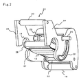
- Fig. 2 is a perspective view which shows a configuration of a printing unit chassis shown in Fig. 1 .
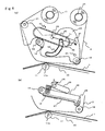
- Fig. 3 is a principal side view which shows the pressed state in which a thermal head shown in Fig. 1 is pressed into contact with a platen roller.
- Fig. 4 is a principal side view which shows the opened state in which the thermal head shown in Fig. 1 is separated from the platen roller.
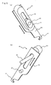
- Fig. 5 is a perspective view which shows a configuration of a head lock lever shown in Fig. 1 .
- Fig. 6 is an explanatory diagram which shows the movement action of the head lock lever shown in Fig. 1 .
- the thermal printer 10 has a configuration including, as a printing unit, a platen roller 11 and a thermal head 12 arranged such that the face thereof on which multiple heaters are formed in the width direction faces the platen roller 11.
- a print target medium 1 which is a consecutive tag set formed of consecutive tags, and an ink ribbon 2 stacked on one another are held and conveyed between the platen roller 11 and the thermal head 12.
- ink is transferred from the ink ribbon 2 to the print target medium 1 by instructing the heaters on the thermal head 12 to selectively generate heat, thereby performing printing processing.
- the print target medium 1 thus printed is cut off at a predetermined position by a cutter device 50 provided in the downstream stage of the printing unit, following which the print target medium 1 thus cut off is discharged.
- the print target medium 1 is rotatably supported in a state in which it is wound onto a tubular member such as a paper tube or the like in the form of a roll, i.e., as a roll paper sheet 3.
- the print target medium 1 is pulled out by holding and conveying the ink ribbon and the print target medium between the platen roller 11 and the thermal head 12.
- the print target medium 1 thus pulled out from a supply shaft 13 is supplied to the nip between the platen roller 11 and the thermal head 12.
- reference numeral 14 shown in Fig. 1 denotes a roll paper sheet guide plate which guides the roll paper sheet 3 mounted to the supply shaft 13.
- Reference numeral 15 shown in Fig. 1 denotes a guide roller which guides the print target medium 1 pulled out from the supply shaft 13 to the nip between the platen roller 11 and the thermal head 12.
- the ink ribbon 2 is set between the ribbon supply shaft 16 and the ribbon winding shaft 17 which is rotationally driven in association with the platen roller 11.
- the unused ink ribbon 2 supported by the ribbon supply shaft 16 in a state in which the ink ribbon 2 has been wound on the ribbon supply shaft 16 in the form of a roll is supplied along with the print target medium 1 to the nip between the platen roller 11 and the thermal head 12.
- the ink ribbon 2 is spooled onto the ribbon winding shaft 17.
- reference numeral 18 shown in Fig. 1 denotes a guide roller which guides the unused ink ribbon 2 supported by the ribbon supply shaft 16 to the nip between the platen roller 11 and the thermal head 12.
- Reference numerals 19 and 20 denote guide rollers which guide the ink ribbon 2 to the ribbon winding shaft 17 after the ink has been transferred.
- the supply shaft 13, the guide roller 15, the ribbon supply shaft 16, and the ribbon winding shaft 17 are supported by a main side plate 21 in a cantilever manner, and a print unit chassis 22 which supports the thermal head 12, the guide roller 18, and the guide roller 20 are supported by the main side plate 21 in a cantilever manner.
- a first side plate 23 and a second side plate 24, which are mounted to the main side plate 21, are arranged opposite to one another at a predetermined interval.
- the guide roller 18 is arranged at the perimeter in the lower portion on the upstream side of the conveying direction for the print target medium 1 (which will be referred to simply as the "conveying direction"), the guide roller 20 is arranged at the perimeter in the upper portion on the upstream side of the conveying direction, and the support shaft 25 is arranged in the lower portion on the relatively downstream side in the conveying direction. Furthermore, a turn shaft 26 is arranged in the upper portion on the downstream side in the conveying direction relative to the support shaft 25 such that it protrudes from the second side plate 24.
- the head support unit 27 which supports the thermal head 12, and a pressing unit 28 which presses the head support unit 27, i.e., the thermal head 12, into contact with the platen roller 11 with a predetermined pressing force are swingably mounted to the support shaft 25.
- the guide roller 19 is mounted on the open end side of the pressing unit 28.
- By turning the turn shaft 26, such an arrangement allows the state to be switched between the pressing state as shown in Fig. 3 in which the thermal head 12 is pressed into contact with the platen roller 11 mounted to a bottom portion 30 and the opened state as shown in Fig. 4 in which the thermal head 12 is separated from the platen roller 11 mounted to the bottom portion 30.
- the turn shaft 26 can be turned using a head lock lever 40 which is mounted to the open end of the turn shaft 26 protruding from the second side plate 24, and which includes a hook 41 which is an engaging means provided to the tip thereof along the longitudinal direction.
- a head lock lever 40 which is mounted to the open end of the turn shaft 26 protruding from the second side plate 24, and which includes a hook 41 which is an engaging means provided to the tip thereof along the longitudinal direction.
- the state is set to the pressed state in which the contact member 29 attached to the turn shaft 26 presses the pressing unit 28 downward such that the thermal head 12 is pressed into contact with the platen roller 11 mounted to the bottom portion 30.
- the printing operation is performed.
- force is applied to the head support unit 27 and the pressing unit 28 using an unshown force applying means such as a spring or the like in a direction in which the thermal head 12 is separated from the platen roller 11, i.e., the direction in which the thermal head 12 is moved upward.
- an unshown force applying means such as a spring or the like in a direction in which the thermal head 12 is separated from the platen roller 11, i.e., the direction in which the thermal head 12 is moved upward.
- engagement between the hook 41 and the engagement shaft 11a maintains the pressed state.
- the replace operation for the ink ribbon 2 is performed, i.e., the ink ribbon 2 is detached and mounted from/to the ribbon supply shaft 16 and the ribbon winding shaft 17.
- the ribbon supply shaft 16, the ribbon winding shaft 17, and the print unit chassis 22 which supports the thermal head 12, the guide roller 18, and the guide roller 20 are supported by the main side plate 21 in a cantilever manner.
- the replacement operation for the ink ribbon 20 is performed on the open end side of the ribbon supply shaft 16, the ribbon winding shaft 17, and the print unit chassis 22.
- the opened state permits the maintenance operation such as cleaning of the platen roller 11 and the thermal head 12 etc., and the sheet feeding operation for the print target medium 1.
- the state can be switched between the pressed state and the opened state by operating the head lock lever 40.
- a configuration is employed in which the distance between the turn shaft 26 and the hook 41 provided to the head lock lever 40 is changed according to the operation of the head lock lever 40. That is to say, with such an arrangement, the head lock lever 40 is moved relative to the turn shaft 26 such that the distance L 2 between the turn shaft 26 and the hook 41 provided to the head lock lever 40 in the opened state shown in Fig. 4(a) is smaller than the distance L 1 between the turn shaft 26 and the hook 41 provided to the head lock lever 40 in the pressed state shown in Fig. 3(a) .
- Fig. 5 shows the head lock lever 40 in a state when a cover 42 has been removed.
- the head lock lever 40 includes a slide unit 43 which is slidably mounted to a slide reception unit 31 fixed at the open end of the turn shaft 26 protruding from the second side plate 24 and a plate member 44 which is fixed to the slide unit 43 and which includes the hook 41 at the tip thereof.
- a slide unit 43 which is slidably mounted to a slide reception unit 31 fixed at the open end of the turn shaft 26 protruding from the second side plate 24 and a plate member 44 which is fixed to the slide unit 43 and which includes the hook 41 at the tip thereof.
- Such an arrangement allows the slide unit 43 to slide in the longitudinal direction of the head lock lever 40. Sliding the slide unit 43 changes the distance between the turn shaft 26 and the tip at which the hook 41 is provided.
- a groove portion 32 is formed in the second side plate 24 of the print unit chassis 22 such that the distance from the turn shaft 26 is reduced according to the movement of the head lock lever 40 in the movable range from the position at which the head lock lever 40 is positioned in the pressed state to the position at which the head lock lever 40 is positioned in the opened state. Furthermore, a protrusion portion 45 is provided to the plate member 44, which is loosely fit to the groove portion 32 formed in the second side plate 24. A combination of the groove portion 32 and the protrusion portion 45 provides a function as a movement control means which allows the head lock lever 40 to be moved in the longitudinal direction.
- the protrusion portion 45 is guided along the groove portion 32 according to the operation of the head lock lever 40, thereby changing the distance between the turn shaft 26 and the protrusion portion 45. That is to say, the distance M 2 between the turn shaft 26 and the protrusion portion 45 in the opened state shown in Fig. 6(b) is smaller than the distance M 1 between the turn shaft 26 and the protrusion portion 45 in the pressed state shown in Fig. 6(a) . Accordingly, the head lock lever 40 is moved relative to the turn shaft 26 such that the distance between the hook 41 which is moved in the form of a single unit with the protrusion unit 45 and the turn shaft 26 in the opened state is smaller than the distance therebetween in the pressed state.
- the hook 41 in the pressed state, the hook 41 is extended such that it can be engaged with the unshown engagement reception shaft 11a arranged concentrically with the platen roller 11, i.e., positioned on the lower side relative to the traveling route for the ink ribbon 2, crossing the traveling route for the ink ribbon 2 as viewed from the open end side. Furthermore, in the opened state, the distance between the turn shaft 26 and the hook 41 is reduced, and the hook 41 is moved to a position at which the hook 41 does not cross the traveling route for the ink ribbon 2 as viewed from the open end side. Thus, such an arrangement allows the ink ribbon 2 to be replaced without interference of the head lock lever 40.
- the present embodiment includes: the head support unit 27 and the pressing unit 28, which support the thermal head 12 and which are swingably mounted to the support shaft 25; the contact means 29 which controls the swing of the head support unit 27 and the pressing unit 28 according to the turn of the turn shaft 26; the head lock lever 40 which includes the hook 41 at the tip thereof along the longitudinal direction, and which is mounted such that it can be moved in the longitudinal direction relative to the turn shaft 26 while turning the turn shaft 26, thereby allowing the distance between the turn shaft 26 and the hook 41 to be changed; and the movement control means which moves the head lock lever 40 such that the distance between the turn shaft 26 and the hook 41 in the opened state in which the thermal head 12 is separated from the platen roller 11 is smaller than that in the pressed state in which the thermal head 12 is pressed into contact with the platen roller 11.
- the present embodiment is configured such that, in the pressed state, the hook 41 is extended such that it can be engaged with the engagement reception shaft 11a and such that it crosses the traveling route for the ink ribbon 2 as viewed from the open end side of the ribbon supply shaft 16 and the ribbon winding shaft 17. On the other hand, in the opened state, the hook 41 is retracted to a position at which the hook 41 does not cross the traveling route for the ink ribbon 2 as viewed from the open end side of the ribbon supply shaft 16 and the ribbon winding shaft 17.
- the movement control means has a configuration including: the groove portion 32 wherein the distance from the turn shaft 26, within a movable range of the head lock lever 40, is reduced from the position at which the head lock lever 40 is positioned in the pressed state towards the position at which the head lock lever 40 is positioned in the opened state; and the protrusion portion 45 provided to the head lock lever 40 and loosely fit to the groove portion 32.
Landscapes
- Electronic Switches (AREA)
- Common Mechanisms (AREA)
- Impression-Transfer Materials And Handling Thereof (AREA)
Claims (2)
- Imprimante thermique qui effectue un traitement d'impression avec un ruban encreur (2), qui a été placé entre un arbre d'alimentation en ruban (16) et un arbre d'enroulement de ruban (17) supporté en porte-à-faux, et des supports cible d'impression (1) empilés les uns sur les autres, en maintenant et en convoyant le ruban encreur et le support cible d'impression entre un rouleau presseur (11) et une tête thermique (12), comprenant :- des moyens de support de tête (27) qui supportent la tête thermique et qui sont montés de façon pivotante sur un arbre de support ;- des moyens de commande de pivotement qui commandent le pivotement des moyens de support de tête suivant la rotation d'un arbre rotatif (26) ;- un levier de verrouillage de tête (40) qui comprend des moyens d'engagement (41) à sa pointe suivant la direction longitudinale, et caractérisée en ce que le levier de verrouillage de tête est monté de façon mobile de sorte qu'il puisse être déplacé dans la direction longitudinale par rapport à l'arbre rotatif tout en tournant l'arbre rotatif, permettant ainsi à la distance entre l'arbre rotatif et les moyens d'engagement d'être changée ;- et en ce que l'imprimante thermique comprend également des moyens de commande de mouvement qui déplacent le levier de verrouillage de tête de sorte que la distance entre l'arbre rotatif et les moyens d'engagement, à l'état ouvert dans lequel la tête thermique est séparée du rouleau presseur, soit inférieure à celle à l'état pressé, dans lequel la tête thermique est pressée au contact de rouleau presseur, étendant ainsi les moyens d'engagement à l'état pressé jusqu'à une position à laquelle les moyens d'engagement peuvent être engagés avec un arbre de réception d'engagement de sorte qu'ils traversent le chemin de passage du ruban encreur, vu depuis le côté d'extrémité ouverte de l'arbre d'alimentation en ruban et de l'arbre d'enroulement de ruban, et rétracte ainsi les moyens d'engagement à l'état ouvert jusqu'à une position à laquelle les moyens d'engagement ne traversent pas le chemin de passage du ruban encreur, vu depuis le côté d'extrémité ouverte de l'arbre d'alimentation en ruban et de l'arbre d'enroulement de ruban.
- Imprimante thermique selon la revendication 1, dans laquelle les moyens de commande de mouvement comprennent :- une partie en rainure dans laquelle la distance depuis l'arbre rotatif, dans une plage de mobilité du levier de verrouillage de tête, est réduite de la position à laquelle le levier de verrouillage de tête est positionné à l'état pressé vers la position à laquelle le levier de verrouillage de tête est positionné à l'état ouvert ; et- une partie en saillie disposée sur le levier de verrouillage de tête et insérée avec du jeu dans la partie en rainure.
Applications Claiming Priority (2)
| Application Number | Priority Date | Filing Date | Title |
|---|---|---|---|
| JP2008038698A JP4252106B1 (ja) | 2008-02-20 | 2008-02-20 | サーマルプリンタ |
| PCT/JP2008/068170 WO2009104300A1 (fr) | 2008-02-20 | 2008-10-06 | Imprimante thermique |
Publications (3)
| Publication Number | Publication Date |
|---|---|
| EP2243633A1 EP2243633A1 (fr) | 2010-10-27 |
| EP2243633A4 EP2243633A4 (fr) | 2012-05-02 |
| EP2243633B1 true EP2243633B1 (fr) | 2013-12-11 |
Family
ID=40612122
Family Applications (1)
| Application Number | Title | Priority Date | Filing Date |
|---|---|---|---|
| EP08872603.9A Active EP2243633B1 (fr) | 2008-02-20 | 2008-10-06 | Imprimante thermique |
Country Status (4)
| Country | Link |
|---|---|
| US (1) | US8284224B2 (fr) |
| EP (1) | EP2243633B1 (fr) |
| JP (1) | JP4252106B1 (fr) |
| WO (1) | WO2009104300A1 (fr) |
Families Citing this family (8)
| Publication number | Priority date | Publication date | Assignee | Title |
|---|---|---|---|---|
| KR101503515B1 (ko) * | 2014-08-18 | 2015-03-18 | (주)선진에스엠 | 스트로크 조절링크를 구비한 고속 스탬프 인쇄장치 |
| JP6631305B2 (ja) * | 2016-02-19 | 2020-01-15 | 沖電気工業株式会社 | サーマルプリンタおよび該サーマルプリンタを備える自動取引装置 |
| US10981395B2 (en) | 2017-09-26 | 2021-04-20 | Sato Holdings Kabushiki Kaisha | Printer |
| US10906327B2 (en) * | 2017-09-26 | 2021-02-02 | Sato Holdings Kabushiki Kaisha | Printer |
| EP3804999B1 (fr) | 2018-06-01 | 2023-09-13 | Sato Holdings Kabushiki Kaisha | Imprimante |
| CN111376620B (zh) * | 2018-12-26 | 2022-04-29 | 精工爱普生株式会社 | 装配于带印刷装置的盒 |
| JP2022057161A (ja) * | 2020-09-30 | 2022-04-11 | セイコーエプソン株式会社 | テープ印刷装置 |
| CN115091866B (zh) * | 2022-08-12 | 2023-11-21 | 杭州标佳数码科技有限公司 | 碳带收卷机构及包含其的打印机 |
Family Cites Families (13)
| Publication number | Priority date | Publication date | Assignee | Title |
|---|---|---|---|---|
| US4641151A (en) * | 1984-12-28 | 1987-02-03 | Victor Company Of Japan, Limited | Thermal transfer recording apparatus |
| JPH06320829A (ja) | 1993-05-14 | 1994-11-22 | Tohoku Ricoh Co Ltd | サーマルプリンタ |
| JPH07256978A (ja) * | 1994-03-25 | 1995-10-09 | Sato:Kk | サーマルプリンタ |
| JPH08169163A (ja) * | 1994-12-19 | 1996-07-02 | Seiko Instr Inc | プリンタ |
| DE19614080C2 (de) | 1995-04-10 | 1999-07-22 | Alps Electric Co Ltd | Thermodrucker |
| JP3812761B2 (ja) | 1996-09-27 | 2006-08-23 | 株式会社サトー | カッターユニットの取付け装置 |
| US6068415A (en) * | 1998-11-11 | 2000-05-30 | Eltron International, Inc. | Printer with floating print head with alignment surfaces to position printhead |
| JP2001310503A (ja) * | 2000-04-28 | 2001-11-06 | Canon Inc | 記録装置 |
| JP4315619B2 (ja) * | 2001-08-29 | 2009-08-19 | 日本モレックス株式会社 | レバー結合式コネクタ |
| JP4338986B2 (ja) * | 2003-02-13 | 2009-10-07 | セイコーインスツル株式会社 | 熱活性化装置 |
| JP4438504B2 (ja) | 2004-04-30 | 2010-03-24 | 富士ゼロックス株式会社 | 定着装置 |
| US7295223B2 (en) * | 2004-07-30 | 2007-11-13 | Samsung Electronics Co., Ltd. | Method and apparatus for adjusting an image alignment for an image forming apparatus |
| JP4589345B2 (ja) | 2006-06-29 | 2010-12-01 | 東芝テック株式会社 | 印刷装置 |
-
2008
- 2008-02-20 JP JP2008038698A patent/JP4252106B1/ja active Active
- 2008-10-06 WO PCT/JP2008/068170 patent/WO2009104300A1/fr not_active Ceased
- 2008-10-06 EP EP08872603.9A patent/EP2243633B1/fr active Active
- 2008-10-06 US US12/918,164 patent/US8284224B2/en active Active
Also Published As
| Publication number | Publication date |
|---|---|
| JP2009196162A (ja) | 2009-09-03 |
| JP4252106B1 (ja) | 2009-04-08 |
| WO2009104300A1 (fr) | 2009-08-27 |
| EP2243633A4 (fr) | 2012-05-02 |
| US8284224B2 (en) | 2012-10-09 |
| US20100321458A1 (en) | 2010-12-23 |
| EP2243633A1 (fr) | 2010-10-27 |
Similar Documents
| Publication | Publication Date | Title |
|---|---|---|
| EP2243633B1 (fr) | Imprimante thermique | |
| JP5106238B2 (ja) | カッター付きプリンタ | |
| EP2292541B1 (fr) | Appareil à découper | |
| JP2012210800A (ja) | プリンタ | |
| JP4752869B2 (ja) | ヘッド移動機構及び画像形成装置 | |
| JP3614730B2 (ja) | プリンタ | |
| US5120147A (en) | Printing device | |
| JP4419737B2 (ja) | テープ/チューブプリンタ | |
| US20110129281A1 (en) | Recording device and recording medium supply mechanism for a recording device | |
| US7878724B2 (en) | Printer | |
| JP5972650B2 (ja) | ラベルプリンタ | |
| JP2015016598A (ja) | プリンター | |
| JP2014061647A (ja) | ラベルプリンタ | |
| JP4803293B2 (ja) | テープ/チューブプリンタ | |
| JP4473377B2 (ja) | 印字装置 | |
| JP6302374B2 (ja) | サーマルプリンタ用紙ガイド装置 | |
| JP2009179013A (ja) | プリンタ | |
| JP5736205B2 (ja) | プリンタ | |
| JP5585049B2 (ja) | プリンタ | |
| JP2004058553A (ja) | プリンタ | |
| JP4589975B2 (ja) | プリンタ | |
| JP2005343643A (ja) | 印刷装置 | |
| JP2008303035A (ja) | スタッカ | |
| JP4914191B2 (ja) | スタッカー | |
| JP2011167910A (ja) | 連続用紙の手動切断用排出装置およびプリンター |
Legal Events
| Date | Code | Title | Description |
|---|---|---|---|
| PUAI | Public reference made under article 153(3) epc to a published international application that has entered the european phase |
Free format text: ORIGINAL CODE: 0009012 |
|
| 17P | Request for examination filed |
Effective date: 20100813 |
|
| AK | Designated contracting states |
Kind code of ref document: A1 Designated state(s): AT BE BG CH CY CZ DE DK EE ES FI FR GB GR HR HU IE IS IT LI LT LU LV MC MT NL NO PL PT RO SE SI SK TR |
|
| AX | Request for extension of the european patent |
Extension state: AL BA MK RS |
|
| DAX | Request for extension of the european patent (deleted) | ||
| A4 | Supplementary search report drawn up and despatched |
Effective date: 20120403 |
|
| RIC1 | Information provided on ipc code assigned before grant |
Ipc: B41J 25/312 20060101AFI20120328BHEP Ipc: B41J 2/32 20060101ALI20120328BHEP Ipc: B41J 25/316 20060101ALI20120328BHEP |
|
| GRAP | Despatch of communication of intention to grant a patent |
Free format text: ORIGINAL CODE: EPIDOSNIGR1 |
|
| INTG | Intention to grant announced |
Effective date: 20130529 |
|
| GRAS | Grant fee paid |
Free format text: ORIGINAL CODE: EPIDOSNIGR3 |
|
| GRAA | (expected) grant |
Free format text: ORIGINAL CODE: 0009210 |
|
| AK | Designated contracting states |
Kind code of ref document: B1 Designated state(s): AT BE BG CH CY CZ DE DK EE ES FI FR GB GR HR HU IE IS IT LI LT LU LV MC MT NL NO PL PT RO SE SI SK TR |
|
| REG | Reference to a national code |
Ref country code: GB Ref legal event code: FG4D |
|
| REG | Reference to a national code |
Ref country code: CH Ref legal event code: EP |
|
| REG | Reference to a national code |
Ref country code: AT Ref legal event code: REF Ref document number: 644302 Country of ref document: AT Kind code of ref document: T Effective date: 20140115 |
|
| REG | Reference to a national code |
Ref country code: NL Ref legal event code: T3 Ref country code: IE Ref legal event code: FG4D |
|
| REG | Reference to a national code |
Ref country code: DE Ref legal event code: R096 Ref document number: 602008029325 Country of ref document: DE Effective date: 20140206 Ref country code: NL Ref legal event code: T3 |
|
| REG | Reference to a national code |
Ref country code: AT Ref legal event code: MK05 Ref document number: 644302 Country of ref document: AT Kind code of ref document: T Effective date: 20131211 |
|
| PG25 | Lapsed in a contracting state [announced via postgrant information from national office to epo] |
Ref country code: SE Free format text: LAPSE BECAUSE OF FAILURE TO SUBMIT A TRANSLATION OF THE DESCRIPTION OR TO PAY THE FEE WITHIN THE PRESCRIBED TIME-LIMIT Effective date: 20131211 Ref country code: LT Free format text: LAPSE BECAUSE OF FAILURE TO SUBMIT A TRANSLATION OF THE DESCRIPTION OR TO PAY THE FEE WITHIN THE PRESCRIBED TIME-LIMIT Effective date: 20131211 Ref country code: NO Free format text: LAPSE BECAUSE OF FAILURE TO SUBMIT A TRANSLATION OF THE DESCRIPTION OR TO PAY THE FEE WITHIN THE PRESCRIBED TIME-LIMIT Effective date: 20140311 Ref country code: HR Free format text: LAPSE BECAUSE OF FAILURE TO SUBMIT A TRANSLATION OF THE DESCRIPTION OR TO PAY THE FEE WITHIN THE PRESCRIBED TIME-LIMIT Effective date: 20131211 Ref country code: FI Free format text: LAPSE BECAUSE OF FAILURE TO SUBMIT A TRANSLATION OF THE DESCRIPTION OR TO PAY THE FEE WITHIN THE PRESCRIBED TIME-LIMIT Effective date: 20131211 |
|
| REG | Reference to a national code |
Ref country code: DE Ref legal event code: R082 Ref document number: 602008029325 Country of ref document: DE Representative=s name: GRUENECKER, KINKELDEY, STOCKMAIR & SCHWANHAEUS, DE Effective date: 20140403 Ref country code: DE Ref legal event code: R081 Ref document number: 602008029325 Country of ref document: DE Owner name: SATO HOLDINGS KABUSHIKI KAISHA, JP Free format text: FORMER OWNER: KABUSHIKI KAISHA SATO, KABUSHIKI KAISHA SATO CHISHIKI, , JP Effective date: 20140403 Ref country code: DE Ref legal event code: R081 Ref document number: 602008029325 Country of ref document: DE Owner name: SATO HOLDINGS KABUSHIKI KAISHA, JP Free format text: FORMER OWNERS: KABUSHIKI KAISHA SATO, TOKIO/TOKYO, JP; KABUSHIKI KAISHA SATO CHISHIKI ZAISAN KENKYUSYO, TOKYO, JP Effective date: 20140403 Ref country code: DE Ref legal event code: R082 Ref document number: 602008029325 Country of ref document: DE Representative=s name: GRUENECKER PATENT- UND RECHTSANWAELTE PARTG MB, DE Effective date: 20140403 |
|
| REG | Reference to a national code |
Ref country code: NL Ref legal event code: SD Effective date: 20140509 Ref country code: NL Ref legal event code: TD Effective date: 20140509 |
|
| REG | Reference to a national code |
Ref country code: LT Ref legal event code: MG4D |
|
| PG25 | Lapsed in a contracting state [announced via postgrant information from national office to epo] |
Ref country code: AT Free format text: LAPSE BECAUSE OF FAILURE TO SUBMIT A TRANSLATION OF THE DESCRIPTION OR TO PAY THE FEE WITHIN THE PRESCRIBED TIME-LIMIT Effective date: 20131211 Ref country code: LV Free format text: LAPSE BECAUSE OF FAILURE TO SUBMIT A TRANSLATION OF THE DESCRIPTION OR TO PAY THE FEE WITHIN THE PRESCRIBED TIME-LIMIT Effective date: 20131211 Ref country code: CY Free format text: LAPSE BECAUSE OF FAILURE TO SUBMIT A TRANSLATION OF THE DESCRIPTION OR TO PAY THE FEE WITHIN THE PRESCRIBED TIME-LIMIT Effective date: 20131211 |
|
| REG | Reference to a national code |
Ref country code: GB Ref legal event code: 732E Free format text: REGISTERED BETWEEN 20140515 AND 20140521 |
|
| PG25 | Lapsed in a contracting state [announced via postgrant information from national office to epo] |
Ref country code: IS Free format text: LAPSE BECAUSE OF FAILURE TO SUBMIT A TRANSLATION OF THE DESCRIPTION OR TO PAY THE FEE WITHIN THE PRESCRIBED TIME-LIMIT Effective date: 20140411 Ref country code: BE Free format text: LAPSE BECAUSE OF FAILURE TO SUBMIT A TRANSLATION OF THE DESCRIPTION OR TO PAY THE FEE WITHIN THE PRESCRIBED TIME-LIMIT Effective date: 20131211 Ref country code: EE Free format text: LAPSE BECAUSE OF FAILURE TO SUBMIT A TRANSLATION OF THE DESCRIPTION OR TO PAY THE FEE WITHIN THE PRESCRIBED TIME-LIMIT Effective date: 20131211 |
|
| PG25 | Lapsed in a contracting state [announced via postgrant information from national office to epo] |
Ref country code: RO Free format text: LAPSE BECAUSE OF FAILURE TO SUBMIT A TRANSLATION OF THE DESCRIPTION OR TO PAY THE FEE WITHIN THE PRESCRIBED TIME-LIMIT Effective date: 20131211 Ref country code: SK Free format text: LAPSE BECAUSE OF FAILURE TO SUBMIT A TRANSLATION OF THE DESCRIPTION OR TO PAY THE FEE WITHIN THE PRESCRIBED TIME-LIMIT Effective date: 20131211 Ref country code: PT Free format text: LAPSE BECAUSE OF FAILURE TO SUBMIT A TRANSLATION OF THE DESCRIPTION OR TO PAY THE FEE WITHIN THE PRESCRIBED TIME-LIMIT Effective date: 20140411 Ref country code: CZ Free format text: LAPSE BECAUSE OF FAILURE TO SUBMIT A TRANSLATION OF THE DESCRIPTION OR TO PAY THE FEE WITHIN THE PRESCRIBED TIME-LIMIT Effective date: 20131211 Ref country code: PL Free format text: LAPSE BECAUSE OF FAILURE TO SUBMIT A TRANSLATION OF THE DESCRIPTION OR TO PAY THE FEE WITHIN THE PRESCRIBED TIME-LIMIT Effective date: 20131211 Ref country code: ES Free format text: LAPSE BECAUSE OF FAILURE TO SUBMIT A TRANSLATION OF THE DESCRIPTION OR TO PAY THE FEE WITHIN THE PRESCRIBED TIME-LIMIT Effective date: 20131211 |
|
| REG | Reference to a national code |
Ref country code: DE Ref legal event code: R097 Ref document number: 602008029325 Country of ref document: DE |
|
| PLBE | No opposition filed within time limit |
Free format text: ORIGINAL CODE: 0009261 |
|
| STAA | Information on the status of an ep patent application or granted ep patent |
Free format text: STATUS: NO OPPOSITION FILED WITHIN TIME LIMIT |
|
| PG25 | Lapsed in a contracting state [announced via postgrant information from national office to epo] |
Ref country code: DK Free format text: LAPSE BECAUSE OF FAILURE TO SUBMIT A TRANSLATION OF THE DESCRIPTION OR TO PAY THE FEE WITHIN THE PRESCRIBED TIME-LIMIT Effective date: 20131211 |
|
| 26N | No opposition filed |
Effective date: 20140912 |
|
| REG | Reference to a national code |
Ref country code: DE Ref legal event code: R097 Ref document number: 602008029325 Country of ref document: DE Effective date: 20140912 |
|
| PG25 | Lapsed in a contracting state [announced via postgrant information from national office to epo] |
Ref country code: SI Free format text: LAPSE BECAUSE OF FAILURE TO SUBMIT A TRANSLATION OF THE DESCRIPTION OR TO PAY THE FEE WITHIN THE PRESCRIBED TIME-LIMIT Effective date: 20131211 |
|
| PG25 | Lapsed in a contracting state [announced via postgrant information from national office to epo] |
Ref country code: LU Free format text: LAPSE BECAUSE OF FAILURE TO SUBMIT A TRANSLATION OF THE DESCRIPTION OR TO PAY THE FEE WITHIN THE PRESCRIBED TIME-LIMIT Effective date: 20141006 Ref country code: MC Free format text: LAPSE BECAUSE OF FAILURE TO SUBMIT A TRANSLATION OF THE DESCRIPTION OR TO PAY THE FEE WITHIN THE PRESCRIBED TIME-LIMIT Effective date: 20131211 |
|
| REG | Reference to a national code |
Ref country code: CH Ref legal event code: PL |
|
| REG | Reference to a national code |
Ref country code: IE Ref legal event code: MM4A |
|
| PG25 | Lapsed in a contracting state [announced via postgrant information from national office to epo] |
Ref country code: CH Free format text: LAPSE BECAUSE OF NON-PAYMENT OF DUE FEES Effective date: 20141031 Ref country code: LI Free format text: LAPSE BECAUSE OF NON-PAYMENT OF DUE FEES Effective date: 20141031 |
|
| REG | Reference to a national code |
Ref country code: FR Ref legal event code: ST Effective date: 20150630 |
|
| PG25 | Lapsed in a contracting state [announced via postgrant information from national office to epo] |
Ref country code: FR Free format text: LAPSE BECAUSE OF NON-PAYMENT OF DUE FEES Effective date: 20141031 |
|
| PG25 | Lapsed in a contracting state [announced via postgrant information from national office to epo] |
Ref country code: IE Free format text: LAPSE BECAUSE OF NON-PAYMENT OF DUE FEES Effective date: 20141006 |
|
| PG25 | Lapsed in a contracting state [announced via postgrant information from national office to epo] |
Ref country code: BG Free format text: LAPSE BECAUSE OF FAILURE TO SUBMIT A TRANSLATION OF THE DESCRIPTION OR TO PAY THE FEE WITHIN THE PRESCRIBED TIME-LIMIT Effective date: 20131211 |
|
| PG25 | Lapsed in a contracting state [announced via postgrant information from national office to epo] |
Ref country code: GR Free format text: LAPSE BECAUSE OF FAILURE TO SUBMIT A TRANSLATION OF THE DESCRIPTION OR TO PAY THE FEE WITHIN THE PRESCRIBED TIME-LIMIT Effective date: 20140312 Ref country code: IT Free format text: LAPSE BECAUSE OF FAILURE TO SUBMIT A TRANSLATION OF THE DESCRIPTION OR TO PAY THE FEE WITHIN THE PRESCRIBED TIME-LIMIT Effective date: 20131211 |
|
| PG25 | Lapsed in a contracting state [announced via postgrant information from national office to epo] |
Ref country code: TR Free format text: LAPSE BECAUSE OF FAILURE TO SUBMIT A TRANSLATION OF THE DESCRIPTION OR TO PAY THE FEE WITHIN THE PRESCRIBED TIME-LIMIT Effective date: 20131211 Ref country code: MT Free format text: LAPSE BECAUSE OF FAILURE TO SUBMIT A TRANSLATION OF THE DESCRIPTION OR TO PAY THE FEE WITHIN THE PRESCRIBED TIME-LIMIT Effective date: 20131211 Ref country code: HU Free format text: LAPSE BECAUSE OF FAILURE TO SUBMIT A TRANSLATION OF THE DESCRIPTION OR TO PAY THE FEE WITHIN THE PRESCRIBED TIME-LIMIT; INVALID AB INITIO Effective date: 20081006 |
|
| P01 | Opt-out of the competence of the unified patent court (upc) registered |
Effective date: 20230413 |
|
| PGFP | Annual fee paid to national office [announced via postgrant information from national office to epo] |
Ref country code: NL Payment date: 20241021 Year of fee payment: 17 |
|
| PGFP | Annual fee paid to national office [announced via postgrant information from national office to epo] |
Ref country code: DE Payment date: 20251021 Year of fee payment: 18 |
|
| PGFP | Annual fee paid to national office [announced via postgrant information from national office to epo] |
Ref country code: GB Payment date: 20251022 Year of fee payment: 18 |