EP2243639A1 - Indicateur de pression - Google Patents
Indicateur de pression Download PDFInfo
- Publication number
- EP2243639A1 EP2243639A1 EP10161081A EP10161081A EP2243639A1 EP 2243639 A1 EP2243639 A1 EP 2243639A1 EP 10161081 A EP10161081 A EP 10161081A EP 10161081 A EP10161081 A EP 10161081A EP 2243639 A1 EP2243639 A1 EP 2243639A1
- Authority
- EP
- European Patent Office
- Prior art keywords
- pressure
- indicator
- pressure chamber
- valve stem
- receiving space
- Prior art date
- Legal status (The legal status is an assumption and is not a legal conclusion. Google has not performed a legal analysis and makes no representation as to the accuracy of the status listed.)
- Withdrawn
Links
- 239000012528 membrane Substances 0.000 claims abstract description 33
- 238000000034 method Methods 0.000 claims description 8
- 230000000007 visual effect Effects 0.000 claims description 2
- 235000012489 doughnuts Nutrition 0.000 claims 2
- 239000007789 gas Substances 0.000 description 8
- 239000000463 material Substances 0.000 description 3
- 230000006978 adaptation Effects 0.000 description 2
- 239000012530 fluid Substances 0.000 description 2
- 238000012986 modification Methods 0.000 description 2
- 230000004048 modification Effects 0.000 description 2
- 238000001816 cooling Methods 0.000 description 1
- 230000003247 decreasing effect Effects 0.000 description 1
- 230000001419 dependent effect Effects 0.000 description 1
- 230000000994 depressogenic effect Effects 0.000 description 1
- 239000000945 filler Substances 0.000 description 1
- 238000010438 heat treatment Methods 0.000 description 1
- 238000004519 manufacturing process Methods 0.000 description 1
- 238000012806 monitoring device Methods 0.000 description 1
- 230000000630 rising effect Effects 0.000 description 1
Images


Classifications
-
- B—PERFORMING OPERATIONS; TRANSPORTING
- B60—VEHICLES IN GENERAL
- B60C—VEHICLE TYRES; TYRE INFLATION; TYRE CHANGING; CONNECTING VALVES TO INFLATABLE ELASTIC BODIES IN GENERAL; DEVICES OR ARRANGEMENTS RELATED TO TYRES
- B60C23/00—Devices for measuring, signalling, controlling, or distributing tyre pressure or temperature, specially adapted for mounting on vehicles; Arrangement of tyre inflating devices on vehicles, e.g. of pumps or of tanks; Tyre cooling arrangements
- B60C23/02—Signalling devices actuated by tyre pressure
- B60C23/04—Signalling devices actuated by tyre pressure mounted on the wheel or tyre
- B60C23/0491—Constructional details of means for attaching the control device
- B60C23/0496—Valve stem attachments positioned outside of the tyre chamber
-
- B—PERFORMING OPERATIONS; TRANSPORTING
- B60—VEHICLES IN GENERAL
- B60C—VEHICLE TYRES; TYRE INFLATION; TYRE CHANGING; CONNECTING VALVES TO INFLATABLE ELASTIC BODIES IN GENERAL; DEVICES OR ARRANGEMENTS RELATED TO TYRES
- B60C23/00—Devices for measuring, signalling, controlling, or distributing tyre pressure or temperature, specially adapted for mounting on vehicles; Arrangement of tyre inflating devices on vehicles, e.g. of pumps or of tanks; Tyre cooling arrangements
- B60C23/02—Signalling devices actuated by tyre pressure
- B60C23/04—Signalling devices actuated by tyre pressure mounted on the wheel or tyre
- B60C23/0408—Signalling devices actuated by tyre pressure mounted on the wheel or tyre transmitting the signals by non-mechanical means from the wheel or tyre to a vehicle body mounted receiver
Definitions
- the invention relates to a pressure indicator. More specifically the invention relates to a pressure indicator suitable for vehicle tires.
- a suboptimal pressure such as a pressure of a vehicle tire below the designed operating pressure of the tire can cause a number of problems, ranging from suboptimal roll resistance, suboptimal grip and excessive wear to a considerable enhancement of the accident probability of the vehicle in question.
- One type of pressure indicating system relates to indicators that can be screwed onto the valve stem of the tube of a vehicle tire.
- An example of such indicators can be found in the United States patent US 6 629 454 .
- This document discloses a screw on type of pressure indicator for vehicle tires, comprising a first and a second pressure chamber separated by a membrane, wherein a first surface of the membrane acts as a first contact terminal, and a first battery pole opposite to the first surface of the membrane acts as a second contact terminal.
- the first contact terminal is connected to an electrical printed circuit, which in turn is connected to an indicator connected to a second pole of the battery.
- the membrane between the chambers flexes, causing the first and second contact terminals to make contact and thereby closing an electrical circuit.
- the battery becomes connected to the indicator through the contacting terminals and the electrical printed circuit.
- the logical printed circuit will generate an intermitted electrical signal which actuates the indicator.
- the indicator comprises a set of light emitting diodes.
- a disadvantage of this system is that the indicator is adding considerable length to the valve stem of the tube and/or tire, leading to impractical space requirements.
- the pressure indicator can for instance reach outside the rim of the wheel and can thus disturb the wheel balance.
- a further disadvantage of this pressure indicator is that the cap needs to be screwed off or at least be un-tightened to calibrate the sensor and/or to equalise the pressure in both the first and the second pressure chamber.
- US-4,763,517 discloses a valve cap pressure indicator that has a display that shows the internal pressure of the tire when the cap is depressed. It is not a continously monitoring device that warns the user when the pressure in the tire becomes too low or to high.
- the battery receiving space is not positioned next to the valve stem receiving space in the radial sense but axially behind the valve stem receiving space. Thus, the length of the know cap is rather large, which is disadvantageous.
- WO2008/043177 is a device that may be mounted on the valve stem of a tire valve and that may be used to measure pressure inside the tire and to wirelessly transmit air pressure information to a receiver. It is, however, not a valve cap that can be used to close off a valve and to itself indicate whether the pressure in the tire is acceptable. Apart from that, when mounted on a tire valve stem, the total length thus obtained is considerable because the device is not a valve cap but an intermediate part on which a cap has to be mounted.
- An object of the invention can be to provide an alternative pressure indicator.
- Another object of the invention can be to provide an alternative pressure indicating system that is less protruding from the valve stem of the tube and/or the tire.
- Still another object of the invention can be to provide a pressure indicator that automatically calibrates.
- a first aspect of the invention can be seen a pressure indicator, suitable for connection on a valve of a tire and/or a tube and for valve stem mounted indication of the pressure inside the tire and/or the tube, the pressure indicator comprising:
- a further aspect of the invention can be seen in a method of indicating and/or checking the pressure of a vehicle tire with the pressure indicator as described above comprising the following step: connecting the indicator on the valve stem of a vehicle tire.
- a vehicle wheel 100 is depicted.
- the vehicle wheel comprises a tire 101 around the rim 103 of a hub 102.
- the hub 102 can be connected to a shaft 105 by means of the connector surface 104 of the hub 102.
- holes 106 are provided for attaching the connector surface 104 to a connector plate (not shown) attached to the shaft 105.
- the hub 102 is connected to the shaft 105 by means of bolts. However any other type off connection for attaching the hub 102 to the shaft 105 can be applied.
- the tire 101 comprises a valve stem 107 having a longitudinal axis A for introducing air into the tire 101.
- a pressure indicator 1 is attached onto the valve stem 107.
- the pressure indicator 1 is only minimally extending in the longitudinal axis from the valve stem 107.
- the arrangement of the pressure indicator on the valve stem is illustrated in figure 6 .
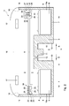
- FIG 2 a cross sectional view of a first embodiment of the pressure indicator 1 is presented.
- a first chamber 2 is provided which can be connected to an inner space 120 of a tube 108. How this connection to the valve stem 107 can be made is illustrated in figure 6 and explained below in more detail.
- the first pressure chamber 2 at least one battery receiving space 18a is provided in the first pressure chamber 2.
- two battery receiving spaces 18a are depicted.
- the battery receiving spaces 18a are, relative to the central longitudinal axis A, positioned offset relative to the central longitudinal axis A of a valve stem receiving space 5.
- the central longitudinal axis A of the valve stem receiving space coincides with the longitudinal axis of the valve stem 107 when the embodiment is mounted on the valves stem 107.
- the battery receiving spaces 18a are in a radial direction R placed next to the valve receiving space 5.
- the pressure indicator 1 protrudes less from the valve stem 107 in the longitudinal direction of the valve stem.
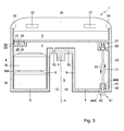
- Figure 3 depicts another embodiment of the pressure indicator 1.
- one battery receiving space 18a is arranged next to the valve stem receiving space 5.
- two or more battery receiving spaces 18a can be arranged next to and/or around the valve receiving space 18a in a suitable arrangement.
- a suitable arrangement in this aspect can be, for instance, that the battery receiving spaces 18a are distributed in substantially equal angles around the valve stem receiving space 5.
- a second pressure chamber 3 is provided in the pressure indicator 1, a second pressure chamber 3 is provided. In the second pressure chamber 3 a reference pressure can be maintained. The first and the second pressure chambers 2, 3 are separated by a wall 6.
- the wall 6 is provided with a membrane compartment 38.
- the membrane compartment 38 comprises a chamber 26 with a first wall 24, on which a second contact terminal 25 is positioned. The second contact terminal 25 can be electrically connected to a first pole of at least one battery 18.
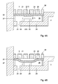
- FIG. 4a and 4b an enlarged cutout view of the membrane compartment 38 is depicted.
- a membrane 22 is positioned inside the membrane compartment 38.
- a first surface of the membrane 22 forms a first contact terminal 22a, and the bottom wall 24 of the membrane compartment 38, is equipped with the second contact terminal 25.
- the first contact terminal 22a can be electrically connected to an indicator 17, which can be for instance embedded in a translucent lens part 16.
- This electrical connection can be direct or through a printed circuit 39, being part of an electrical circuit E, depicted schematically in figure 7 .
- the printed circuit 39 can for instance generate an intermitted signal causing the one or more indicators 17 to provide an intermittent signal at for instance a desired predetermined frequency.
- the membrane compartment 38 further comprises a membrane support member 20, wherein holes 21 are provided for allowing the membrane 22 to experience the reference pressure of the second pressure chamber 3.
- the support member 20 will support the membrane 22 and prevent the membrane 22 from collapsing or flexing in the direction F2 opposite to the intended flexing direction F1.
- the membrane 22 will flex as is depicted in figure 4b . As can be seen, by the flexing of the membrane 22, a contact is made between the terminals 22a and 25, thus closing the electrical circuit E ( figure 7 ).
- the first pressure chamber 2 is connected to a second pressure chamber 3 through check valve (here shown as a non return valve) 27.
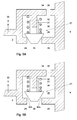
- check valve 27 is depicted in more detail.
- the check valve 27 can be equipped with a closing member 30 which is attached to a guiding sleeve 31.
- the guiding sleeve 31 is arranged around a guiding rod 36, connected to and extending from the first valve housing part 34.
- the closing member 30 is forced against a seat 29 inside a valve housing 33 by means of a spring 32.
- the spring 32 is arranged around the guiding sleeve 31 and the guiding rod 36 and forces the closing member 30 to abut and to close of the seat 29 of the valve 27.
- the housing 33 of the valve 27 is further provided with an opening 35 towards the second pressure chamber 3. If the pressure in the first pressure chamber 2 is higher than the pressure in the second pressure chamber 3, the pressure in the first pressure chamber 2 will force the closing member 30 out of the seat 29 so that gasses can enter through the valve space 28 and the opening 35 into the second pressure chamber 3.
- the spring 32 will force the guiding sleeve 31 and the closing member 30 back towards their original position, wherein the closing member 30 again abuts the seat 29.
- a reset button 41 is provided.
- the reset button 41 comprises a pushing knob 42, which is connected to an actuating rod 43.
- the actuating rod 43 abuts the closing member 30 of the valve 27.
- the actuating rod is gas tight connected to the lower wall 7 of the pressure indicator 1.
- This gas tight connection can be constructed as a bellow seal 44, covering an e.g. integrated spring 45.
- a first side 44a of the bellow seal 44 is gas tight connected to the lower wall 7, a second side 44b of the bellow seal 44 is gas tight connected to the actuating rod 43.
- the spring 45 which is placed inside the bellow seal 44 or is integrated within the bellow seal 44, maintains the actuating rod 43 at its position and can urge the actuating rod 43 back to its original position when the push knob 42 is pressed by a user.
- the push knob 42 and the actuating rod 43 move in direction p1. Since the actuating rod 43 abuts the closing member 30 of the check valve 27, by pushing the reset button 41, the check valve 27 opens and the pressure in the first pressure chamber 2 and the second pressure chamber 3 can thus be equalized.
- This reset button thus can open the check valve 27, such that the reference pressure in pressure chamber 3 can be equalized for instance when it is substantially higher than the pressure in the pressure chamber 2 and/or in the tire 100 or inner tube 108.
- This reset button can be of practical use if for instance due to severe temperature changes, the pressure in the pressure chamber 3 is higher than the pressure in the pressure chamber 2 and/or the pressure in the tire 100 or the inner tube 108.
- the indicator 1 can for instance give a low pressure alarm, where it is in the actual situation only due to for instance rapid heating of the pressure indicator 1 and/or rapid cooling of the tire 100.
- the membrane 22 can for instance be made slightly permeable or porous.
- the connection of the pressure indicator 1 onto the valve stem 107 is visualized.
- the inner tube 108 is arranged inside the outer tube 101 and around the rim 103 of the hub 104.
- the valve stem 107 is connected to the inner tube 108 trough the connection structure 109.
- the inner tube 108 can be molded or poured in a form or mold and can be vulcanized with the valve stem 107 already being inserted inside the inner tube material in order to have a firm and gas tight connection between the stem 107 and the inner tube 108.
- the vehicle tire can be of a tubeless type.
- the valve stem 107 is directly and airtight connected to the rim 103.
- the pressure indicator can be applied in a similar way to tires of the tubeless type.
- the valve stem 107 contains a valve 121 like for instance a Schrader valve.
- This valve 121 comprises an axially moveable valve closing element 114.
- the valve closing element 114 can be a longitudinally extending rod 117 having on the tube side 120 a closing member 108 and on the extending end 121 a knob 119.
- the knob 119 can be rounded off in order to smoothly interact with a valve opener 11 of the pressure indicator 1 or a valve opener of a filling device such as a tire pump or a filler hose of a compressor device.
- the valve stem 107 is on the outside circumference provided with a thread 122.
- the thread 122 can cooperate with the inside thread 13 of the valve receiving space 5 of the pressure indicator 1.
- the pressure indicator 1 can be screwed on the valve stem 107.
- the valve opener 11 will urge the valve rod 114 in the direction of the inner valve space 110. This motion will push against the knob 119 on the rod 117, thus releasing the closing member 118 from the seat 111, opening the valve 121 and thus establishing a fluid connection between the interior space 120 of the vehicle tire 100 and the first pressure chamber 2.
- the first pressure chamber 2 Since the fluid connection is established, the first pressure chamber 2 will experience a pressure that is substantially equal to the pressure in the tire 100 or the tube 108. During the rising of the pressure in the first pressure chamber 2, a pressure difference will occur between the first and the second pressure chamber 3. This pressure difference will urge the check valve 27 to open and allow gasses inside the second pressure chamber 3. The pressures in the tire 100 and both pressure chambers 2 and 3 will now be substantially the same. During the service life of the tire 100, due to for instance a slightly porosity of the material of the tire 100 and/or the tube 108, the pressure will gradually decrease. Since the first pressure chamber 2 and the inner space 120 of the tube 10 or the tire 100 are connected, the pressure in the first pressure chamber 2 is decreasing as well. Since the first and second pressure chambers 2 and 3 are only connected by means of the check valve 27, the pressure in the second pressure chamber 3 will substantially be maintained.
- the pressure in the tire 100 and in the first pressure chamber 2 will be sufficiently less than the pressure in the second pressure chamber 3 to flex the membrane 22.
- the contact terminals 22a and 25 will make contact, thus closing the electrical circuit E.
- a signal will be generated by the one or more indicators 17, alarming the driver and/or others that a dangerous situation is developing in that the tire pressure dropped below a threshold.
- the pressure difference between the pressure chambers 2 and 3 will decrease.
- the membrane 22 will stop being flexed, thus breaking the contact between the terminals 22a and 25.
- the electrical circuit E is broken and the alarm signal will be stopped.
- the presure indicator 1 can be equipped with a lower collar that supports on the rim 103 of the wheel 100. Thus impacts on the pressure indicator 1 will be less likely to impair the pressure indicator 1.
- the indication of low tire pressure can also be performed by e.g. a sonic indicator and/or a signal transmitter, transmitting a signal for instance to a receiver in the dashboard of a vehicle.
- the indicator can alternatively be connected to a vehicle main electrical circuit interrupter, such that at low pressures the vehicle refuses to drive. This interrupter can for instance be integrated in the vehicle motor management system.
Landscapes
- Engineering & Computer Science (AREA)
- Mechanical Engineering (AREA)
- Measuring Fluid Pressure (AREA)
Applications Claiming Priority (1)
| Application Number | Priority Date | Filing Date | Title |
|---|---|---|---|
| NL2002802A NL2002802C2 (en) | 2009-04-24 | 2009-04-24 | PRESSURE INDICATOR. |
Publications (1)
| Publication Number | Publication Date |
|---|---|
| EP2243639A1 true EP2243639A1 (fr) | 2010-10-27 |
Family
ID=41353931
Family Applications (1)
| Application Number | Title | Priority Date | Filing Date |
|---|---|---|---|
| EP10161081A Withdrawn EP2243639A1 (fr) | 2009-04-24 | 2010-04-26 | Indicateur de pression |
Country Status (2)
| Country | Link |
|---|---|
| EP (1) | EP2243639A1 (fr) |
| NL (1) | NL2002802C2 (fr) |
Citations (6)
| Publication number | Priority date | Publication date | Assignee | Title |
|---|---|---|---|---|
| US4763517A (en) | 1987-06-16 | 1988-08-16 | Feinberg Andrew S | Valve cap pressure indicator |
| WO1996036861A1 (fr) * | 1995-05-16 | 1996-11-21 | Hines Wragg John Alexander | Capuchon de valve a detection de pression laissant passer l'air |
| US6300867B1 (en) | 2000-06-01 | 2001-10-09 | Ryan M. Rea | Tire low pressure audio warning device |
| US20020059825A1 (en) * | 2000-11-21 | 2002-05-23 | Lundqvist Torbjorn Boson | Tire pressure monitoring device |
| US20070044552A1 (en) * | 2005-08-31 | 2007-03-01 | Teng-Wen Huang | Tire pressure detector |
| WO2008043177A1 (fr) | 2006-10-13 | 2008-04-17 | Smartire Systems Inc. | Procédé et appareil de détection de pression fluidique |
-
2009
- 2009-04-24 NL NL2002802A patent/NL2002802C2/en not_active IP Right Cessation
-
2010
- 2010-04-26 EP EP10161081A patent/EP2243639A1/fr not_active Withdrawn
Patent Citations (7)
| Publication number | Priority date | Publication date | Assignee | Title |
|---|---|---|---|---|
| US4763517A (en) | 1987-06-16 | 1988-08-16 | Feinberg Andrew S | Valve cap pressure indicator |
| WO1996036861A1 (fr) * | 1995-05-16 | 1996-11-21 | Hines Wragg John Alexander | Capuchon de valve a detection de pression laissant passer l'air |
| US6300867B1 (en) | 2000-06-01 | 2001-10-09 | Ryan M. Rea | Tire low pressure audio warning device |
| US20020059825A1 (en) * | 2000-11-21 | 2002-05-23 | Lundqvist Torbjorn Boson | Tire pressure monitoring device |
| US6629454B2 (en) | 2000-11-21 | 2003-10-07 | Lundqvist Torbjoern Boson | Tire pressure monitoring device |
| US20070044552A1 (en) * | 2005-08-31 | 2007-03-01 | Teng-Wen Huang | Tire pressure detector |
| WO2008043177A1 (fr) | 2006-10-13 | 2008-04-17 | Smartire Systems Inc. | Procédé et appareil de détection de pression fluidique |
Also Published As
| Publication number | Publication date |
|---|---|
| NL2002802C2 (en) | 2010-10-26 |
Similar Documents
| Publication | Publication Date | Title |
|---|---|---|
| US5774047A (en) | Tire pressure sensing system including improved switch and location indicator | |
| AU2002219805B2 (en) | Tire pressure monitoring device | |
| US7509849B2 (en) | Tire pressure gauge with data transmitter | |
| EP2994323B1 (fr) | Système complet de maintien de la pression dans un pneumatique | |
| US6817235B2 (en) | Tire pressure sensor | |
| AU2002219805A1 (en) | Tire pressure monitoring device | |
| EP1661736A2 (fr) | Dispositif de valve | |
| US6100798A (en) | Tire pressure detecting/warning apparatus | |
| KR20140138703A (ko) | 타이어 공기압 감지 장치 및 그 제조방법 | |
| US20040025581A1 (en) | Method and apparatus for monitoring tire pressure with a color indicator | |
| GB2490302A (en) | TYre pressure warning system | |
| US6595046B2 (en) | Temperature and pressure compensating indicator | |
| US6588264B1 (en) | Pressure indicating devices | |
| US20190047337A1 (en) | System for monitoring tire pressure and method for mounting a tire pressure monitoring system on a rim | |
| EP2243639A1 (fr) | Indicateur de pression | |
| CN1894115A (zh) | 用于充气轮胎的卸压装置 | |
| NL2005070C2 (en) | A pressure indicating valve cap for mounting on a valve stem of a vehicle tire. | |
| WO2002081236A1 (fr) | Dispositifs de controle de la pression de pneus | |
| US20010023613A1 (en) | Pressure gauge for vehicle tires | |
| US7178389B2 (en) | Method and apparatus for scavenging and using energy caused by changes in pressure | |
| US7327244B2 (en) | Valve device with pressure alarm for tire | |
| KR20130013754A (ko) | 타이어 공기압 지시 밸브 캡 | |
| US20050217364A1 (en) | Air valve housing with tire pressure indicator | |
| OA10074A (en) | Tyre fault warning device | |
| WO2004048128A2 (fr) | Detecteur de pression pour pneus |
Legal Events
| Date | Code | Title | Description |
|---|---|---|---|
| PUAI | Public reference made under article 153(3) epc to a published international application that has entered the european phase |
Free format text: ORIGINAL CODE: 0009012 |
|
| AK | Designated contracting states |
Kind code of ref document: A1 Designated state(s): AT BE BG CH CY CZ DE DK EE ES FI FR GB GR HR HU IE IS IT LI LT LU LV MC MK MT NL NO PL PT RO SE SI SK SM TR |
|
| AX | Request for extension of the european patent |
Extension state: AL BA ME RS |
|
| 17P | Request for examination filed |
Effective date: 20110421 |
|
| RIC1 | Information provided on ipc code assigned before grant |
Ipc: B60C 23/00 20060101AFI20110606BHEP |
|
| GRAP | Despatch of communication of intention to grant a patent |
Free format text: ORIGINAL CODE: EPIDOSNIGR1 |
|
| STAA | Information on the status of an ep patent application or granted ep patent |
Free format text: STATUS: THE APPLICATION IS DEEMED TO BE WITHDRAWN |
|
| 18D | Application deemed to be withdrawn |
Effective date: 20111208 |