EP2243662A1 - Vorrichtung zur Beleuchtung und/oder Signalisierung für Kraftfahrzeuge - Google Patents
Vorrichtung zur Beleuchtung und/oder Signalisierung für Kraftfahrzeuge Download PDFInfo
- Publication number
- EP2243662A1 EP2243662A1 EP09305350A EP09305350A EP2243662A1 EP 2243662 A1 EP2243662 A1 EP 2243662A1 EP 09305350 A EP09305350 A EP 09305350A EP 09305350 A EP09305350 A EP 09305350A EP 2243662 A1 EP2243662 A1 EP 2243662A1
- Authority
- EP
- European Patent Office
- Prior art keywords
- support
- movable block
- block
- guide
- vehicle
- Prior art date
- Legal status (The legal status is an assumption and is not a legal conclusion. Google has not performed a legal analysis and makes no representation as to the accuracy of the status listed.)
- Granted
Links
- 230000011664 signaling Effects 0.000 title claims abstract description 27
- 238000007747 plating Methods 0.000 claims abstract description 11
- 238000006073 displacement reaction Methods 0.000 claims abstract description 5
- 239000002184 metal Substances 0.000 claims description 24
- 230000000295 complement effect Effects 0.000 claims description 6
- 230000004224 protection Effects 0.000 claims description 5
- 230000000149 penetrating effect Effects 0.000 claims description 3
- 239000003550 marker Substances 0.000 abstract 1
- 230000035939 shock Effects 0.000 description 6
- 229920002994 synthetic fiber Polymers 0.000 description 5
- 239000000872 buffer Substances 0.000 description 4
- 238000013016 damping Methods 0.000 description 2
- 239000013536 elastomeric material Substances 0.000 description 2
- 238000009434 installation Methods 0.000 description 2
- 230000000284 resting effect Effects 0.000 description 2
- 210000000078 claw Anatomy 0.000 description 1
- 230000006835 compression Effects 0.000 description 1
- 238000007906 compression Methods 0.000 description 1
- 230000006378 damage Effects 0.000 description 1
- 230000000593 degrading effect Effects 0.000 description 1
- 230000000694 effects Effects 0.000 description 1
- 229920001971 elastomer Polymers 0.000 description 1
- 239000000806 elastomer Substances 0.000 description 1
- 238000001125 extrusion Methods 0.000 description 1
- 238000002513 implantation Methods 0.000 description 1
- 230000001788 irregular Effects 0.000 description 1
- 238000000465 moulding Methods 0.000 description 1
- 210000000056 organ Anatomy 0.000 description 1
- 230000003014 reinforcing effect Effects 0.000 description 1
- 230000003252 repetitive effect Effects 0.000 description 1
- 239000000725 suspension Substances 0.000 description 1
Images


Classifications
-
- B—PERFORMING OPERATIONS; TRANSPORTING
- B60—VEHICLES IN GENERAL
- B60Q—ARRANGEMENT OF SIGNALLING OR LIGHTING DEVICES, THE MOUNTING OR SUPPORTING THEREOF OR CIRCUITS THEREFOR, FOR VEHICLES IN GENERAL
- B60Q1/00—Arrangement of optical signalling or lighting devices, the mounting or supporting thereof or circuits therefor
- B60Q1/26—Arrangement of optical signalling or lighting devices, the mounting or supporting thereof or circuits therefor the devices being primarily intended to indicate the vehicle, or parts thereof, or to give signals, to other traffic
- B60Q1/30—Arrangement of optical signalling or lighting devices, the mounting or supporting thereof or circuits therefor the devices being primarily intended to indicate the vehicle, or parts thereof, or to give signals, to other traffic for indicating rear of vehicle, e.g. by means of reflecting surfaces
- B60Q1/305—Indicating devices for towed vehicles
-
- B—PERFORMING OPERATIONS; TRANSPORTING
- B60—VEHICLES IN GENERAL
- B60Q—ARRANGEMENT OF SIGNALLING OR LIGHTING DEVICES, THE MOUNTING OR SUPPORTING THEREOF OR CIRCUITS THEREFOR, FOR VEHICLES IN GENERAL
- B60Q1/00—Arrangement of optical signalling or lighting devices, the mounting or supporting thereof or circuits therefor
- B60Q1/26—Arrangement of optical signalling or lighting devices, the mounting or supporting thereof or circuits therefor the devices being primarily intended to indicate the vehicle, or parts thereof, or to give signals, to other traffic
- B60Q1/2657—Arrangement of optical signalling or lighting devices, the mounting or supporting thereof or circuits therefor the devices being primarily intended to indicate the vehicle, or parts thereof, or to give signals, to other traffic mounted on a shaft, e.g. telescopic
Definitions
- the invention relates to the field of lighting and / or signaling devices for vehicles, and in particular the devices arranged at the rear of a road transport vehicle of goods such as a truck or a trailer.
- Road freight vehicles have their rear particularly subjected to shocks.
- trucks or trailers are often pushed back against loading / unloading docks.
- Massive stops connected to the chassis of the vehicle, and sometimes mounted on a spring element, allow to collect the impact of the vehicle on the loading dock. These stops are located at the height of the load plate of the truck or trailer.
- the trucks or their trailers are equipped with underrun bars arranged at the height of the bumpers of passenger vehicles.
- the rear of trucks or trailers can also be equipped with fixed buffers to back the trailer as close to a wall.
- damping pads may extend vertically between the vehicle loading platform and the underride bar.
- stop lamps change of direction indicators, or reversing indicators
- reversing indicators are particularly delicate. Indeed, these must be visible from the rear of the vehicle. They often include lamps or LEDs surrounded by a cabochon of particularly fragile synthetic material. Such lights have for example been implanted slightly recessed with respect to underrun bars, any cylinder stops, or buffer dampers. This prevents the driver from crushing the taillights of his truck by pulling it back against the unloading dock. The removal of the fire with respect to the various abutment members is however limited by the need for these organs to remain visible.
- cabochons taillight truck are often broken, without the fire itself is broken.
- the quantity of these small incidents is quite important.
- the causes can be multiple.
- unloading docks may have irregular obstacles that protrude slightly from the dock, such as stones or metal stops.
- the unloading maneuvers on the platform of a rear tailgate of the trailer or truck can hit the taillight and break the cabochons.
- a large manually loaded crate can hit the taillight and break a cabochon.
- the invention aims in particular to reduce the impact of these small anomalies on traffic lights.
- signaling devices for motorcycles such as indicator lights change of direction. Some of these lights are mounted on a support of elastomeric material. During a shock at low speed, such fires retract and return to approximately their initial position.
- traffic lights are not suitable for trucks because the normal position of use is not precise.
- road freight vehicles are subject to high amplitude vibrations due to road irregularities and suspensions of the vehicle. If signal lights oscillated with respect to an average position, there is the risk that the signal perceived by a user following the vehicle, appears flashing. This could be a source of error or accident.
- the invention proposes a lighting and / or signaling device for vehicles, in particular for the transport of road goods of the truck or trailer type, which overcomes the aforementioned drawbacks, and in particular which makes it possible to better control the normal position of use. fires while avoiding the destruction of the device by shocks of reduced amplitude.
- the lighting and / or vehicle signaling device comprises a support equipped with a means of attachment to the vehicle and a movable block having a reference position relative to the support and being equipped with least one signaling element intended to be illuminated. It comprises a resilient return means adapted to return the movable block to said reference position when the movable block is located in an automatic return displacement zone and to exert a plating force between the support and the moving block when the latter is in the reference position.
- the moving zone of the self-returning mobile block allows the block to retract under the pressure of slightly intrusive objects.
- the signaling element (s) are then only subjected to the force of the elastic return means which remains much lower than the mechanical strength of the possible cabochons of lights.
- the fire returns to its reference position when the slightly intrusive object retreats.
- the plating force in the reference position prevents the signal element from oscillating under the effect of its own inertia. This makes it possible to better control the reference position of the device.
- the elastic return means may be a helical or spiral metal spring or blade, an elastomeric block or a gas compass.
- the support may be an insert on the chassis of the vehicle or part of the chassis itself.
- the movable block and the support are rigid and comprise complementary complementary guide surfaces, when the block is in the reference position relative to the support, to immobilize five degrees of freedom and to limit the relative displacement in one direction according to the sixth degree of freedom, the plating force exerted in the opposite direction to said direction of movement limited by the guide surfaces.
- the guide means allows the device to retract in the direction of the degree of freedom left free in one direction. . This avoids breaking the cabochons of fires.
- the device remains in the reference position as the force exerted is less than the plating force exerted by the biasing means.
- the degree of freedom left free can be a rotation or a translation.
- the block is rotatable relative to the support about a pivot axis.
- the pivot axis is offset laterally with respect to all the signaling elements in a direction perpendicular to the vehicle advance.
- a shock from the rear of the vehicle on signal elements rotates the movable block about the pivot axis.
- the reference position is defined by complementary bearing surfaces of the movable block and the radially remote support of the pivot axis.
- the device comprises a first guide element equipped with a sleeve and a second guide element equipped with a guide shaft movable in translation in the sleeve, the guide shaft and the sleeve being coaxial with the pivot axis, one of the two guide elements being fixed to the support, the other guide element being fixed to the movable block.
- the elastic return means is arranged to exert a force between the two guide elements in the pivot axis.
- the spring can act in compression or extension, the reference position corresponds to a prestressing configuration of the spring.
- the guide shaft is rotatable relative to the sleeve and in which at least one of the guide elements has a surface inclined with respect to the pivot axis and extending at a radial distance from the pivot axis, the other guide member having a bearing surface, the guide members being so designed that the bearing surface is adapted to engage and slide along the inclined surface; inclined. While the bearing surface slides along the inclined surface, the guide elements are movable relative to each other in a helical path. A stop along this path, and maintaining support between the two aforementioned surfaces to control the relative position of the two guide elements and define the reference position of the device.
- the first inclined surface is extended by a disengagement surface, perpendicular to the axis of the guide shaft, the guide element not comprising the disengagement surface being adapted to cooperate with said disengagement surface, the block moving out of the automatic return zone.
- the return spring exerts an axial force perpendicular to the clearance surface. This allows the lighting and / or signaling device not to be destroyed if the intrusive shock on said device requires a displacement of the upper movable block to the area of return to automatic return.
- the device may include an indicator of the exit of the automatic return zone.
- This indicator may be a breakable key or an electric switch actuated when the opposite guide member cooperates with the clearance surface.
- the switch may extinguish the lights and / or send an error message to the driver's cab of the vehicle.
- the first guide element comprises a first interface flank extending radially at one end of the sleeve
- the second guide element comprises a second interface flank extending radially out of the shaft and located opposite the first interface flank, one of the first or second interface flank comprising a V-shaped groove, the other interface flank comprising a V-shaped rib, corresponding to the V e of the groove and having an axis of rib intersecting the pivot axis.
- the axial plating of the rib in the groove fixes the relative position of the two guide elements in rotation and in translation. This determines the reference position of the moving block relative to the support.
- the rotation is accompanied by a slight axial translation which compresses or extends the spring beyond the prestressing configuration.
- the device comprises a metal shaft fixed at the center of the guide shaft, the elastic return means comprising a helical spring axially abutting between the first guide element and said metal axis.
- the elastic return means comprising a helical spring axially abutting between the first guide element and said metal axis.
- the movable block comprises a block metal armature having a guide bore fitted to said metal axis and extending over most of the radial extent of said movable block.
- the external force exerted on the moving block is transmitted by the metal frame of the block to the metal axis of the support. This reduces the mechanical stresses to which the other components of the moving block are subjected when the latter is displaced by an external force. This can reduce, for example, the stresses in external shells or in the electronic circuits supplying the signaling elements of the block.
- the first guide element is integrated in the support, said support comprising a metal armature having means for fixing the support to the chassis of the vehicle and a reinforcing bore surrounding the guide sleeve.
- the movable block and the support further comprise arcuate cylinder surfaces facing one another, said surfaces each having a light through which a power supply conduit passes. This allows the power supply conduits are always protected by the device and out of the support to go along the frame.
- the elastic return means comprises at least one helical spring whose end bears against a fixed abutment integral with the support, the other end of the spring bearing on a movable abutment integral with the movable block.
- the elastic return means comprises a monobloc elastomer spring having two coaxial cylindrical cylindrical portions, one of the portions receiving a polygonal shaft adjusted and fixed to the movable block (respectively to the support), the other portion being received in a seat attached to the support (respectively to the moving block).
- the mobile block comprises a rigid monobloc assembly equipped with a main plate on which is disposed the at least one signaling element and a side plate penetrating into at least one light of the support able to define a articulation axis, the elastic return means being designed to press the lateral plate against the support at at least one point distant from the axis of articulation.
- the light can be a vertical slot. Several lights can be aligned along the hinge axis. Alternatively, the side plate can be connected to the support by aligned elastomeric pivots.
- the invention also relates to a vehicle equipped with an underrun system, of the truck or trailer type, comprising a lighting and / or signaling device arranged at the rear of the vehicle so that the signaling elements, when the moving block is in the reference position, are set back and above the underride system and the automatic return travel zone is further set back towards the front of the vehicle.
- "Underrun protection” means a horizontal underride bar or a rear tailgate section that complies with the applicable legislation on underrun protection.
- the underride bars are generally slightly reduced compared to possible backstops on cylinders or damping buffer. Thus, the potential shocks of large amplitude do not reach the device. Other rear impacts, of reduced amplitude, do not cause the device to break because the mobile block can move in the automatic return zone.
- the vehicle comprises a longitudinal central frame on which is fixed the support.
- the rear face of a goods road transport vehicle such as a truck or a trailer, comprises passive stops 1, generally made of elastomeric material, spring-backing pads 2 mounted on spring elements and equipped with horizontal rollers; underrun bar 3 and two lighting and / or signaling devices 4 fixed on the outer faces 5 of the beams 6 of the chassis of the vehicle.
- the passive stops 1 are arranged along a threshold bar 7 just below the level of the loading floor and the opening of the doors 8.
- Passive stops 1 are also arranged vertically on the height of the beams 6 of the frame.
- the reversing pads 2 allow to roll along a vertical edge of the loading dock. This avoids degrading the dock during the gradual raising of the vehicle load plate during the unloading of the vehicle.
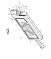
- Each of the lighting and / or signaling devices 4 of the vehicle comprises a support 9 whose attachment on the outer face 5 will be detailed in FIG. figure 7 .
- the device 4 also comprises a movable block 10 articulated in the support 9 around a vertical pivot axis 11.
- the movable block 10 comprises a series of light-emitting signaling elements 12 and one or more retro-reflectors.
- the signaling elements 12 emitting the light may either provide an indication, such as direction indicators, stop lamps, sidelights or fog lamps, others serve to illuminate as well as to give an indication such as the reversing lamps .
- the movable block 10 is extended at its outer end by a horn 13 mounted on an elastomeric support, and indicating the extreme bulk of the vehicle.
- the moving block 10, as well as the luminous elements 12 that it contains, are located at a distance or at most in line with an end rear surface 14 of the underrun bar 3.
- the recoil pad 2 protrudes at the rear of the trailer or truck beyond the extreme surface 14.
- the maximum retracted position 2a of the recoil pad 2 is shown in dashed line on the figure 2 .
- the device 4 is set back from this maximum retracted position 2a.
- the reversing buffer 2, the vertical passive stop 1 and the underrun protection bar 3 constitute so many protections of the signaling device 4.
- the latter pivots around the axis of vertical pivoting 11 from the reference position shown in full lines on the Figures 2 and 3 to an extreme non-functional position.
- the automatic return to the reference position is ensured regardless of the pivoting position between the reference position and an automatic return end position 16.
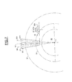
- the support 9 comprises a base 33 and a protrusion 34 containing a sleeve 35.
- the support 9 comprises a first interface flank 36 normal to the vertical pivot axis 11.
- the interface flank 36 comprises two circular lips 31 and 32 concentric.
- Each of the lips 31 and 32 is equipped with two V-shaped grooves having inclined surfaces 38 and 39 respectively.
- the apex angle of the inclined surfaces 38, 39 of each V-groove is proportional to the diameter of the circular lip 31, 32 on each side. which is located said groove Vee.
- the sheath 35 and the two V-shaped grooves 38 and 39 constitute the first guiding element 23 of the device 4.
- the lips 31, 32 also contribute to the stiffness of the first interface flank 36.
- the base 33 of the support 9 has a surface 54 in a cylinder arc comprising a slot 40 intended to correspond to the light 29 of the movable support 10.
- the top lips 31, 32 constitute a clearance surface 41 against which the rib vertex 25 can slide ( figures 6 , 7 ) once these out of the grooves Vee 38 and 39.
- the movable block 10 is of generally rectangular shape and has a lateral protrusion 19 projecting from a small side 21 of the rectangle.
- the mobile block 10 comprises a front outer shell 17 and a back 18.
- the outer front shell 17 is perforated according to the legislation in force and shows the signaling elements 12.
- a guide shaft 20 protrudes from the lateral protrusion 19 and extends along the pivot axis 11 in parallel and at a radial distance from the recessed lateral side 21 of the movable block 10.
- the guide shaft 20 is connected at the lateral protrusion 19 by a second interface flank 24 extending out of the guide shaft 20 on one side of the lateral protrusion 19.
- the guide shaft 20 is fitted to the sleeve 35 and slides in said sleeve 35 in rotation and in slight translation.
- the second interface flank 24 is opposite the first interface flank 36.
- the second interface flank 24 comprises two ribs 25 projecting from a flat portion 26 of the second interface flank 24.
- the two ribs 25 are arranged in two diametrically opposite radii on either side of the guide shaft. 20 along a rib axis 52 and each comprise two inclined surfaces 27 and 27a.
- the guide shaft 20 and the rib 25 constitute a second guide element 22 of the device 4.
- the lateral protrusion 19 also comprises a cylindrical arc surface 28 having a slot 29 extending along a plane perpendicular to the vertical pivot axis 11.
- a metal shaft 44 is fitted into the guide shaft 20 which is integral with the back 18 of synthetic material.
- the metal axis 44 protrudes outside the guide shaft 20 on a side opposite to the lateral protrusion 19.
- the inclined surfaces 27 and 27a of the ribs 25 are arranged so that their median lines 30 and 30a in a radial plane, pass through the vertical pivot axis 11.
- the inclination of the surfaces 27, 27a varies so that proportional to the distance to the vertical pivot axis 11.
- the V groove 38 of the larger diameter lip 31 causes the same block elevation. mobile 10 that the groove Vee 39 less flared and located on the lip 32 of smaller diameter.
- the device further comprises a block frame 42 and an electronic box 43 enclosing the light signaling elements not shown. These can be, for example, bulbs or LEDs.
- the electronic box 43 and the block frame 42 are inserted between the front outer shell 17 and the back 18.
- the block frame 42 comprises orifices 53 intended to receive the metal axis 44.
- the support 9 comprises a metal frame 45 overmolded within a support body 46.
- the sheath 35 and the first interface flank 36 are integral with the support body 46.
- the metal armature 45 comprises a bore 47 surrounding the sheath 35 of synthetic material.
- the metal frame 45 also comprises fixing screws 51.
- a helical spring 48 is disposed between the metal frame 45 and a washer 49 integral with the metal axis 44.
- the device 4 comprises a hinge about the vertical pivot axis 11 for which all the surfaces intended to be in frictional contact with each other are made of synthetic material so as to reduce friction.
- the first interface flank 36, the second interface flank 24, the sleeve 35 and the guide shaft 20 are obtained by molding.
- this same joint comprises a succession of metal frames 45, 44 and 42 for ensuring the rigidity of the joint. This allows reduced friction forces while having high plating efforts.
- the electronic box 43 is substantially sealed.
- a power supply conduit 50 leaks from the box 43 and passes through the corresponding slots 46 and 29 of the mobile block 10 and the support 9.
- the device 4 has a reference position determined by the plating of the rib 25 in the grooves 38, 39.
- the movable block 10 can pivot about the pivot axis 11. As long as the surfaces 27 or 27a of the rib 25 are supported on the inclined surfaces 38, 39 of the Vee grooves, the movable block 10 is in the area of movement to return automatically to the reference position. As soon as the rib 25 slides on the clearance surfaces 41, the moving block leaves the automatic return movement zone.
- the second embodiment comprises a movable block 60 and a U-shaped support 62.
- the movable block 60 has a generally parallelepipedal shape and contains an assembly 61 of signaling elements.
- the bottom of the U-shape of the support 62 is fixed on the chassis beam 6.
- the device also comprises a cylindrical pivot shaft 63 of circular cross section through corresponding orifices in horizontal walls 64 of the movable block 60 and in side walls. 65 of the U-shape of the support 62.
- the device also comprises two helical springs 66 surrounding the pivot shaft 63.
- Each spring 66 has a first end 67 resting on a lug 68 of one of the side walls 65 of the support 62 and a second end 69 resting on a vertical wall 70 of the movable block 60.
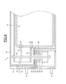
- the horizontal walls 64 of the movable block 60 have an arcuate shape illustrated in dashed lines on the figure 11 so that the assembly of the movable block can pivot about the axis 71 of the pivot shaft 63.
- the vertical wall 70 of the movable block 60 serves as a support against support 80. This support defines the reference position. In this position, the spring 66 is prestressed.
- the elastic return means comprises a monobloc elastomeric spring 75 obtained by extrusion and having two portions 76 and 77 cylindrical, hollow, coaxial and of square cross section. Portion 76 is located within portion 77. A square section pivot shaft 78 fitted to elastomeric portion 76 is secured in two square slots of horizontal walls 64 of movable block 60. Elastomeric outer portion 77 is adjusted. in a metal tube 79 of corresponding square section and fixed on a U-shaped support 80. A vertical wall 70 of the movable block 60 serves as a support against the support 80. This support defines the reference position. The elastomeric spring is at rest when the inner 76 and outer 77 portions are offset by 45 °. In the reference position illustrated in figure 11 , the elastomeric spring is prestressed at an angle of 5 to 20 °.
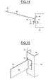
- the fourth embodiment comprises a support 85 which is a part of the chassis beam 6 and a T-shaped movable block 86.
- the movable block 86 comprises a vertically disposed main plate 87 on which a set of elements is fixed. signaling not shown.
- the movable block 86 also includes a side plate 88 perpendicular to the main plate 87, having a rear vertical recess 89 penetrating into a corresponding vertical slot 90 of the support 85.
- the device also comprises a spring mechanism 91 pulling the side plate 88 against the The light 90 and the vertical recess 89 define a pivot axis 93 of the device.
- the spring mechanism 91 is prestressed. Thus the pivoting takes place only from a certain threshold of effort on the moving block.
Landscapes
- Engineering & Computer Science (AREA)
- Mechanical Engineering (AREA)
- Lighting Device Outwards From Vehicle And Optical Signal (AREA)
Priority Applications (4)
| Application Number | Priority Date | Filing Date | Title |
|---|---|---|---|
| ES09305350T ES2388402T3 (es) | 2009-04-24 | 2009-04-24 | Dispositivo de iluminación y/o de señalización para vehículo |
| DK09305350.2T DK2243662T3 (da) | 2009-04-24 | 2009-04-24 | Belysnings- og/eller signaleringsapparat til køretøj |
| AT09305350T ATE553957T1 (de) | 2009-04-24 | 2009-04-24 | Vorrichtung zur beleuchtung und/oder signalisierung für kraftfahrzeuge |
| EP09305350A EP2243662B1 (de) | 2009-04-24 | 2009-04-24 | Vorrichtung zur Beleuchtung und/oder Signalisierung für Kraftfahrzeuge |
Applications Claiming Priority (1)
| Application Number | Priority Date | Filing Date | Title |
|---|---|---|---|
| EP09305350A EP2243662B1 (de) | 2009-04-24 | 2009-04-24 | Vorrichtung zur Beleuchtung und/oder Signalisierung für Kraftfahrzeuge |
Publications (2)
| Publication Number | Publication Date |
|---|---|
| EP2243662A1 true EP2243662A1 (de) | 2010-10-27 |
| EP2243662B1 EP2243662B1 (de) | 2012-04-18 |
Family
ID=41057340
Family Applications (1)
| Application Number | Title | Priority Date | Filing Date |
|---|---|---|---|
| EP09305350A Not-in-force EP2243662B1 (de) | 2009-04-24 | 2009-04-24 | Vorrichtung zur Beleuchtung und/oder Signalisierung für Kraftfahrzeuge |
Country Status (4)
| Country | Link |
|---|---|
| EP (1) | EP2243662B1 (de) |
| AT (1) | ATE553957T1 (de) |
| DK (1) | DK2243662T3 (de) |
| ES (1) | ES2388402T3 (de) |
Cited By (2)
| Publication number | Priority date | Publication date | Assignee | Title |
|---|---|---|---|---|
| FR3073797A1 (fr) * | 2017-11-20 | 2019-05-24 | Lamberet | Dispositif de signalisation et d’eclairage |
| TWI815671B (zh) * | 2022-09-23 | 2023-09-11 | 和碩聯合科技股份有限公司 | 方向燈控制機構 |
Citations (6)
| Publication number | Priority date | Publication date | Assignee | Title |
|---|---|---|---|---|
| US4058720A (en) * | 1976-03-01 | 1977-11-15 | Renfrow Lonnie C | Suspension means for automobile fog light |
| US4658335A (en) * | 1981-10-13 | 1987-04-14 | Culler Daniel L | Resilient mounting mechanism for vehicle tail lights |
| FR2686846A1 (fr) | 1992-02-04 | 1993-08-06 | Daimler Benz Ag | Fixation laterale, au chassis, d'un tube support de feu arriere ou d'aile de camion ou de remorque. |
| US6164804A (en) * | 1998-08-12 | 2000-12-26 | Self; Walter H. | Truck light bar and mudflap holder apparatus |
| US20030200623A1 (en) * | 2002-04-03 | 2003-10-30 | Wen-Yi Hung | Two stage compressive spring operated door check hinge |
| EP1959076A1 (de) * | 2007-02-15 | 2008-08-20 | Westag & Getalit AG | Schließautomat für einen Tür-oder Fensterflügel |
-
2009
- 2009-04-24 DK DK09305350.2T patent/DK2243662T3/da active
- 2009-04-24 EP EP09305350A patent/EP2243662B1/de not_active Not-in-force
- 2009-04-24 ES ES09305350T patent/ES2388402T3/es active Active
- 2009-04-24 AT AT09305350T patent/ATE553957T1/de active
Patent Citations (6)
| Publication number | Priority date | Publication date | Assignee | Title |
|---|---|---|---|---|
| US4058720A (en) * | 1976-03-01 | 1977-11-15 | Renfrow Lonnie C | Suspension means for automobile fog light |
| US4658335A (en) * | 1981-10-13 | 1987-04-14 | Culler Daniel L | Resilient mounting mechanism for vehicle tail lights |
| FR2686846A1 (fr) | 1992-02-04 | 1993-08-06 | Daimler Benz Ag | Fixation laterale, au chassis, d'un tube support de feu arriere ou d'aile de camion ou de remorque. |
| US6164804A (en) * | 1998-08-12 | 2000-12-26 | Self; Walter H. | Truck light bar and mudflap holder apparatus |
| US20030200623A1 (en) * | 2002-04-03 | 2003-10-30 | Wen-Yi Hung | Two stage compressive spring operated door check hinge |
| EP1959076A1 (de) * | 2007-02-15 | 2008-08-20 | Westag & Getalit AG | Schließautomat für einen Tür-oder Fensterflügel |
Cited By (3)
| Publication number | Priority date | Publication date | Assignee | Title |
|---|---|---|---|---|
| FR3073797A1 (fr) * | 2017-11-20 | 2019-05-24 | Lamberet | Dispositif de signalisation et d’eclairage |
| EP3492316A1 (de) * | 2017-11-20 | 2019-06-05 | Lamberet | Signalisierungs- und beleuchtungsvorrichtung |
| TWI815671B (zh) * | 2022-09-23 | 2023-09-11 | 和碩聯合科技股份有限公司 | 方向燈控制機構 |
Also Published As
| Publication number | Publication date |
|---|---|
| DK2243662T3 (da) | 2012-07-30 |
| ATE553957T1 (de) | 2012-05-15 |
| EP2243662B1 (de) | 2012-04-18 |
| ES2388402T3 (es) | 2012-10-15 |
Similar Documents
| Publication | Publication Date | Title |
|---|---|---|
| EP2432954B1 (de) | Handgriff für ein türblatt eines fahrzeugs | |
| FR2758779A1 (fr) | Ensemble formant pare-chocs de vehicule | |
| EP1893469A1 (de) | Geführter unterbereich der front eines automobils | |
| EP1808332A2 (de) | Vorrichtung zur Montage einer Leuchtenanordnung zwischen Strukturelementen eines Kraftfahrzeugs und Leuchtenanordnung, die eine solche Montagevorrichtung umfasst | |
| FR2630986A1 (fr) | Palier lateral elastique pour vehicule ferroviaire | |
| EP0936118B1 (de) | Fahrzeug, insbesondere Schienenfahrzeug, mit einer Vorrichtung zur Energieverzerrung | |
| EP2243662B1 (de) | Vorrichtung zur Beleuchtung und/oder Signalisierung für Kraftfahrzeuge | |
| FR3065433B1 (fr) | Dispositif de detection ou de communication articule et vehicule correspondant | |
| FR2842152A1 (fr) | Armature de pare-chocs avec elements absorbeur de chocs perfectionne | |
| EP1601558B1 (de) | Schutzvorrichtung gegen stösse für eine fahrzeugvorderseite | |
| EP1827943A2 (de) | Stossdämpfungsvorrichtung für eisenbahnfahrzeug | |
| EP1645465B1 (de) | System zur Montage eines Scheinwerfers an einem Fahrzeug und Fahrzeug mit einem solchen Montagesystem | |
| FR2901202A1 (fr) | Projecteur de vehicule automobile et vehicule automobile comportant un tel projecteur | |
| EP1683691B1 (de) | Motorhauben-Anschlag für Fahrzeug versenkbar im Fall eines Aufschlags | |
| FR2844755A1 (fr) | Projecteur de vehicule automobile comportant un systeme d'amortissement | |
| US11597346B2 (en) | Sensor for activating a vehicle-sensitive locking mechanism of a belt retractor | |
| FR2944547A1 (fr) | Dispositif de debrayage de tringle de serrure de porte pour vehicule, serrure de porte de vehicule et vehicule ainsi equipes | |
| EP3445617A1 (de) | Stossfänger eines kraftfahrzeugs mit beleuchtungsvorrichtungen mit eingeformtem schutzschirm zum schutz des fahrgestells im fall eines aufpralls | |
| FR3059616B1 (fr) | Dispositif d'eclairage et/ou de signalisation lumineuse comprenant des moyens de fixation sur un vehicule automobile | |
| FR3099733A1 (fr) | Seuil de porte passif pour un véhicule | |
| EP2142401B1 (de) | Stossfängerquerträger und energieabsorber anordnung | |
| EP3492316A1 (de) | Signalisierungs- und beleuchtungsvorrichtung | |
| EP1750972B1 (de) | Verbesserte scheinwerfer für kraftfahrzeuge | |
| FR2896212A1 (fr) | Dispositif d'absorption d'energie en cas de choc pour vehicule automobile. | |
| FR3131717A1 (fr) | Boîtier de projecteur pour véhicule automobile pourvu d’une rampe de guidage |
Legal Events
| Date | Code | Title | Description |
|---|---|---|---|
| PUAI | Public reference made under article 153(3) epc to a published international application that has entered the european phase |
Free format text: ORIGINAL CODE: 0009012 |
|
| AK | Designated contracting states |
Kind code of ref document: A1 Designated state(s): AT BE BG CH CY CZ DE DK EE ES FI FR GB GR HR HU IE IS IT LI LT LU LV MC MK MT NL NO PL PT RO SE SI SK TR |
|
| 17P | Request for examination filed |
Effective date: 20110228 |
|
| 17Q | First examination report despatched |
Effective date: 20110315 |
|
| GRAP | Despatch of communication of intention to grant a patent |
Free format text: ORIGINAL CODE: EPIDOSNIGR1 |
|
| RIC1 | Information provided on ipc code assigned before grant |
Ipc: B60Q 1/30 20060101ALI20110930BHEP Ipc: B60Q 1/26 20060101AFI20110930BHEP |
|
| RIN1 | Information on inventor provided before grant (corrected) |
Inventor name: COURTEILLE, BENOIT Inventor name: GAVARD, JEAN-MARC |
|
| GRAS | Grant fee paid |
Free format text: ORIGINAL CODE: EPIDOSNIGR3 |
|
| GRAA | (expected) grant |
Free format text: ORIGINAL CODE: 0009210 |
|
| AK | Designated contracting states |
Kind code of ref document: B1 Designated state(s): AT BE BG CH CY CZ DE DK EE ES FI FR GB GR HR HU IE IS IT LI LT LU LV MC MK MT NL NO PL PT RO SE SI SK TR |
|
| REG | Reference to a national code |
Ref country code: GB Ref legal event code: FG4D Free format text: NOT ENGLISH |
|
| REG | Reference to a national code |
Ref country code: CH Ref legal event code: EP |
|
| REG | Reference to a national code |
Ref country code: IE Ref legal event code: FG4D Free format text: LANGUAGE OF EP DOCUMENT: FRENCH |
|
| REG | Reference to a national code |
Ref country code: AT Ref legal event code: REF Ref document number: 553957 Country of ref document: AT Kind code of ref document: T Effective date: 20120515 |
|
| REG | Reference to a national code |
Ref country code: DE Ref legal event code: R096 Ref document number: 602009006437 Country of ref document: DE Effective date: 20120614 |
|
| REG | Reference to a national code |
Ref country code: NL Ref legal event code: T3 |
|
| REG | Reference to a national code |
Ref country code: DK Ref legal event code: T3 |
|
| REG | Reference to a national code |
Ref country code: AT Ref legal event code: MK05 Ref document number: 553957 Country of ref document: AT Kind code of ref document: T Effective date: 20120418 |
|
| LTIE | Lt: invalidation of european patent or patent extension |
Effective date: 20120418 |
|
| REG | Reference to a national code |
Ref country code: ES Ref legal event code: FG2A Ref document number: 2388402 Country of ref document: ES Kind code of ref document: T3 Effective date: 20121015 |
|
| PG25 | Lapsed in a contracting state [announced via postgrant information from national office to epo] |
Ref country code: LT Free format text: LAPSE BECAUSE OF FAILURE TO SUBMIT A TRANSLATION OF THE DESCRIPTION OR TO PAY THE FEE WITHIN THE PRESCRIBED TIME-LIMIT Effective date: 20120418 Ref country code: CY Free format text: LAPSE BECAUSE OF FAILURE TO SUBMIT A TRANSLATION OF THE DESCRIPTION OR TO PAY THE FEE WITHIN THE PRESCRIBED TIME-LIMIT Effective date: 20120418 Ref country code: IS Free format text: LAPSE BECAUSE OF FAILURE TO SUBMIT A TRANSLATION OF THE DESCRIPTION OR TO PAY THE FEE WITHIN THE PRESCRIBED TIME-LIMIT Effective date: 20120818 Ref country code: PL Free format text: LAPSE BECAUSE OF FAILURE TO SUBMIT A TRANSLATION OF THE DESCRIPTION OR TO PAY THE FEE WITHIN THE PRESCRIBED TIME-LIMIT Effective date: 20120418 Ref country code: FI Free format text: LAPSE BECAUSE OF FAILURE TO SUBMIT A TRANSLATION OF THE DESCRIPTION OR TO PAY THE FEE WITHIN THE PRESCRIBED TIME-LIMIT Effective date: 20120418 Ref country code: SE Free format text: LAPSE BECAUSE OF FAILURE TO SUBMIT A TRANSLATION OF THE DESCRIPTION OR TO PAY THE FEE WITHIN THE PRESCRIBED TIME-LIMIT Effective date: 20120418 Ref country code: NO Free format text: LAPSE BECAUSE OF FAILURE TO SUBMIT A TRANSLATION OF THE DESCRIPTION OR TO PAY THE FEE WITHIN THE PRESCRIBED TIME-LIMIT Effective date: 20120718 |
|
| PG25 | Lapsed in a contracting state [announced via postgrant information from national office to epo] |
Ref country code: GR Free format text: LAPSE BECAUSE OF FAILURE TO SUBMIT A TRANSLATION OF THE DESCRIPTION OR TO PAY THE FEE WITHIN THE PRESCRIBED TIME-LIMIT Effective date: 20120719 Ref country code: SI Free format text: LAPSE BECAUSE OF FAILURE TO SUBMIT A TRANSLATION OF THE DESCRIPTION OR TO PAY THE FEE WITHIN THE PRESCRIBED TIME-LIMIT Effective date: 20120418 Ref country code: HR Free format text: LAPSE BECAUSE OF FAILURE TO SUBMIT A TRANSLATION OF THE DESCRIPTION OR TO PAY THE FEE WITHIN THE PRESCRIBED TIME-LIMIT Effective date: 20120418 Ref country code: MC Free format text: LAPSE BECAUSE OF NON-PAYMENT OF DUE FEES Effective date: 20120430 Ref country code: PT Free format text: LAPSE BECAUSE OF FAILURE TO SUBMIT A TRANSLATION OF THE DESCRIPTION OR TO PAY THE FEE WITHIN THE PRESCRIBED TIME-LIMIT Effective date: 20120820 Ref country code: LV Free format text: LAPSE BECAUSE OF FAILURE TO SUBMIT A TRANSLATION OF THE DESCRIPTION OR TO PAY THE FEE WITHIN THE PRESCRIBED TIME-LIMIT Effective date: 20120418 |
|
| REG | Reference to a national code |
Ref country code: IE Ref legal event code: MM4A |
|
| PG25 | Lapsed in a contracting state [announced via postgrant information from national office to epo] |
Ref country code: IE Free format text: LAPSE BECAUSE OF NON-PAYMENT OF DUE FEES Effective date: 20120424 Ref country code: CZ Free format text: LAPSE BECAUSE OF FAILURE TO SUBMIT A TRANSLATION OF THE DESCRIPTION OR TO PAY THE FEE WITHIN THE PRESCRIBED TIME-LIMIT Effective date: 20120418 Ref country code: RO Free format text: LAPSE BECAUSE OF FAILURE TO SUBMIT A TRANSLATION OF THE DESCRIPTION OR TO PAY THE FEE WITHIN THE PRESCRIBED TIME-LIMIT Effective date: 20120418 Ref country code: SK Free format text: LAPSE BECAUSE OF FAILURE TO SUBMIT A TRANSLATION OF THE DESCRIPTION OR TO PAY THE FEE WITHIN THE PRESCRIBED TIME-LIMIT Effective date: 20120418 Ref country code: AT Free format text: LAPSE BECAUSE OF FAILURE TO SUBMIT A TRANSLATION OF THE DESCRIPTION OR TO PAY THE FEE WITHIN THE PRESCRIBED TIME-LIMIT Effective date: 20120418 Ref country code: EE Free format text: LAPSE BECAUSE OF FAILURE TO SUBMIT A TRANSLATION OF THE DESCRIPTION OR TO PAY THE FEE WITHIN THE PRESCRIBED TIME-LIMIT Effective date: 20120418 |
|
| PLBE | No opposition filed within time limit |
Free format text: ORIGINAL CODE: 0009261 |
|
| STAA | Information on the status of an ep patent application or granted ep patent |
Free format text: STATUS: NO OPPOSITION FILED WITHIN TIME LIMIT |
|
| PG25 | Lapsed in a contracting state [announced via postgrant information from national office to epo] |
Ref country code: MK Free format text: LAPSE BECAUSE OF FAILURE TO SUBMIT A TRANSLATION OF THE DESCRIPTION OR TO PAY THE FEE WITHIN THE PRESCRIBED TIME-LIMIT Effective date: 20120418 Ref country code: IT Free format text: LAPSE BECAUSE OF FAILURE TO SUBMIT A TRANSLATION OF THE DESCRIPTION OR TO PAY THE FEE WITHIN THE PRESCRIBED TIME-LIMIT Effective date: 20120418 |
|
| 26N | No opposition filed |
Effective date: 20130121 |
|
| REG | Reference to a national code |
Ref country code: DE Ref legal event code: R097 Ref document number: 602009006437 Country of ref document: DE Effective date: 20130121 |
|
| PG25 | Lapsed in a contracting state [announced via postgrant information from national office to epo] |
Ref country code: MT Free format text: LAPSE BECAUSE OF FAILURE TO SUBMIT A TRANSLATION OF THE DESCRIPTION OR TO PAY THE FEE WITHIN THE PRESCRIBED TIME-LIMIT Effective date: 20120418 Ref country code: BG Free format text: LAPSE BECAUSE OF FAILURE TO SUBMIT A TRANSLATION OF THE DESCRIPTION OR TO PAY THE FEE WITHIN THE PRESCRIBED TIME-LIMIT Effective date: 20120718 |
|
| REG | Reference to a national code |
Ref country code: CH Ref legal event code: PL |
|
| PG25 | Lapsed in a contracting state [announced via postgrant information from national office to epo] |
Ref country code: LI Free format text: LAPSE BECAUSE OF NON-PAYMENT OF DUE FEES Effective date: 20130430 Ref country code: CH Free format text: LAPSE BECAUSE OF NON-PAYMENT OF DUE FEES Effective date: 20130430 |
|
| PG25 | Lapsed in a contracting state [announced via postgrant information from national office to epo] |
Ref country code: TR Free format text: LAPSE BECAUSE OF FAILURE TO SUBMIT A TRANSLATION OF THE DESCRIPTION OR TO PAY THE FEE WITHIN THE PRESCRIBED TIME-LIMIT Effective date: 20120418 |
|
| PG25 | Lapsed in a contracting state [announced via postgrant information from national office to epo] |
Ref country code: LU Free format text: LAPSE BECAUSE OF NON-PAYMENT OF DUE FEES Effective date: 20120424 |
|
| PG25 | Lapsed in a contracting state [announced via postgrant information from national office to epo] |
Ref country code: HU Free format text: LAPSE BECAUSE OF FAILURE TO SUBMIT A TRANSLATION OF THE DESCRIPTION OR TO PAY THE FEE WITHIN THE PRESCRIBED TIME-LIMIT Effective date: 20090424 |
|
| REG | Reference to a national code |
Ref country code: FR Ref legal event code: PLFP Year of fee payment: 8 |
|
| REG | Reference to a national code |
Ref country code: FR Ref legal event code: PLFP Year of fee payment: 9 |
|
| REG | Reference to a national code |
Ref country code: FR Ref legal event code: PLFP Year of fee payment: 10 |
|
| PGFP | Annual fee paid to national office [announced via postgrant information from national office to epo] |
Ref country code: NL Payment date: 20200313 Year of fee payment: 12 Ref country code: DK Payment date: 20200331 Year of fee payment: 12 |
|
| PGFP | Annual fee paid to national office [announced via postgrant information from national office to epo] |
Ref country code: BE Payment date: 20200415 Year of fee payment: 12 |
|
| REG | Reference to a national code |
Ref country code: DK Ref legal event code: EBP Effective date: 20210430 |
|
| REG | Reference to a national code |
Ref country code: NL Ref legal event code: MM Effective date: 20210501 |
|
| REG | Reference to a national code |
Ref country code: BE Ref legal event code: MM Effective date: 20210430 |
|
| PG25 | Lapsed in a contracting state [announced via postgrant information from national office to epo] |
Ref country code: NL Free format text: LAPSE BECAUSE OF NON-PAYMENT OF DUE FEES Effective date: 20210501 |
|
| PG25 | Lapsed in a contracting state [announced via postgrant information from national office to epo] |
Ref country code: DK Free format text: LAPSE BECAUSE OF NON-PAYMENT OF DUE FEES Effective date: 20210430 |
|
| PGFP | Annual fee paid to national office [announced via postgrant information from national office to epo] |
Ref country code: FR Payment date: 20220330 Year of fee payment: 14 |
|
| PG25 | Lapsed in a contracting state [announced via postgrant information from national office to epo] |
Ref country code: BE Free format text: LAPSE BECAUSE OF NON-PAYMENT OF DUE FEES Effective date: 20210430 |
|
| PGFP | Annual fee paid to national office [announced via postgrant information from national office to epo] |
Ref country code: GB Payment date: 20220519 Year of fee payment: 14 Ref country code: ES Payment date: 20220512 Year of fee payment: 14 Ref country code: DE Payment date: 20220511 Year of fee payment: 14 |
|
| P01 | Opt-out of the competence of the unified patent court (upc) registered |
Effective date: 20230525 |
|
| REG | Reference to a national code |
Ref country code: DE Ref legal event code: R119 Ref document number: 602009006437 Country of ref document: DE |
|
| GBPC | Gb: european patent ceased through non-payment of renewal fee |
Effective date: 20230424 |
|
| PG25 | Lapsed in a contracting state [announced via postgrant information from national office to epo] |
Ref country code: GB Free format text: LAPSE BECAUSE OF NON-PAYMENT OF DUE FEES Effective date: 20230424 |
|
| PG25 | Lapsed in a contracting state [announced via postgrant information from national office to epo] |
Ref country code: GB Free format text: LAPSE BECAUSE OF NON-PAYMENT OF DUE FEES Effective date: 20230424 Ref country code: FR Free format text: LAPSE BECAUSE OF NON-PAYMENT OF DUE FEES Effective date: 20230430 Ref country code: DE Free format text: LAPSE BECAUSE OF NON-PAYMENT OF DUE FEES Effective date: 20231103 |
|
| REG | Reference to a national code |
Ref country code: ES Ref legal event code: FD2A Effective date: 20240531 |
|
| PG25 | Lapsed in a contracting state [announced via postgrant information from national office to epo] |
Ref country code: ES Free format text: LAPSE BECAUSE OF NON-PAYMENT OF DUE FEES Effective date: 20230425 |
|
| PG25 | Lapsed in a contracting state [announced via postgrant information from national office to epo] |
Ref country code: ES Free format text: LAPSE BECAUSE OF NON-PAYMENT OF DUE FEES Effective date: 20230425 |