EP2243885A1 - Dispositif de commutation pour extraire de l'eau d'un bac de lavage - Google Patents
Dispositif de commutation pour extraire de l'eau d'un bac de lavage Download PDFInfo
- Publication number
- EP2243885A1 EP2243885A1 EP08871131A EP08871131A EP2243885A1 EP 2243885 A1 EP2243885 A1 EP 2243885A1 EP 08871131 A EP08871131 A EP 08871131A EP 08871131 A EP08871131 A EP 08871131A EP 2243885 A1 EP2243885 A1 EP 2243885A1
- Authority
- EP
- European Patent Office
- Prior art keywords
- slideway
- sliding shaft
- section
- open
- stop position
- Prior art date
- Legal status (The legal status is an assumption and is not a legal conclusion. Google has not performed a legal analysis and makes no representation as to the accuracy of the status listed.)
- Granted
Links
Images


Classifications
-
- E—FIXED CONSTRUCTIONS
- E03—WATER SUPPLY; SEWERAGE
- E03C—DOMESTIC PLUMBING INSTALLATIONS FOR FRESH WATER OR WASTE WATER; SINKS
- E03C1/00—Domestic plumbing installations for fresh water or waste water; Sinks
- E03C1/12—Plumbing installations for waste water; Basins or fountains connected thereto; Sinks
- E03C1/22—Outlet devices mounted in basins, baths, or sinks
- E03C1/23—Outlet devices mounted in basins, baths, or sinks with mechanical closure mechanisms
- E03C1/2304—Outlet devices mounted in basins, baths, or sinks with mechanical closure mechanisms the actuation force being transmitted to the plug via flexible elements, e.g. chain, Bowden cable
Definitions
- the present invention relates to the washing tank field, especially, to an open/close device of the washing tank drain system.
- the ordinary open/close device of the washing tank drain is designed to be connected with a drain plug, so that users have to reach their hands into water to pull or press the plug in order to fulfil the action of opening or closing.
- Other open/close devices use some connecting mechanisms to connect the open/close part in the plug; thereby the connecting mechanisms bring about the open/close part of the plug to open or close the plug.
- this type of device has more complicated structure, and accordingly gets rise to inconvenient operation and extra work.
- the object of the present invention is to furnish an open/close device of the washing tank drain system, which can be operated more easily and has longer service life.
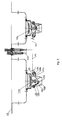
- the open/close device comprises an open/close controller and a drain plug mechanism with an open/close function mechanism; a connecting cable is set between the open/close controller and the open/close function mechanism of the drain plug mechanism.
- Said open/close controller has a sliding shaft, a fixed sleeve with a sliding through hole in it for allowing the sliding shaft to slide through, and a retaining hook for stopping the sliding shaft from moving; said sliding shaft has a first stop position and a second stop position on its surface in order to be movably engaged with the hook part of the retaining hook; said first stop position and second stop position are configured at the different height of the surface of the sliding shaft, the first stop position being closer to the head of the sliding shaft than the second stop position; a first one-way slideway is set on the surface of the sliding shaft allowing the sliding shaft to move from the point where the first stop position is movably engaged with the hook part of the retaining hook to the point where the second stop position is movably engaged with the hook part; a second one-way
- the sliding shaft can do up-and-down movement, and accordingly causes the connecting cable, and in turn the swing arm, to correspondingly move so as to open or close the drain plug; in addition, the sliding shaft will keep a fixed position once the up or down movement is fully finished, so that users don't have to hold it, which not only brings convenient usage, but also prolong the service life.
- the numerical designator 200 represents the place to install an open/close controller
- the numerical designator 300 represent the place to install a water faucet.
- the present invention comprises an open/close controller and a drain plug mechanism 100a with an open/close function mechanism.
- a connecting cable 101 connects the open/close controller with the open/close function mechanism of the drain plug mechanism.
- 108 represents a fixed base for fixing the open/close controller in a washing tank; 109 is a ruber pad set between the fixed base and the washing tank.
- 110 is a nut connected via thread to the fixed base; 111 is a rubber pad set between the nut and the washing tank drain system.
- Said open/close controller includes a sliding shaft 2 and a fixed sleeve with a sliding through hole 37 in it.
- the tail of the sliding shaft is connected via thread with a button 1.
- the manner of connection might be different, such as make a rib and a corresponding groove onto the button and the tail of the sliding shaft, respectively.
- Said open/close controller has a spring 4 which can push the sliding shaft to move in the direction from the head 21 to the tail of the sliding shaft 4.
- Said connecting cable has an end connected with the sliding shaft 2 of the open/close controller.
- said open/close function mechanism is a swing arm 102 which, by swinging movement, can open or close the plug mechanism 100a of the washing tank drain system.
- the other end of the connecting cable is connected with the free end 102a of said swing arm 102 and causes the swing arm to swing back and forth by pulling the free end.
- the numerical designator 103 represents the axis of rotation of the swing arm 102.
- 100b is the ascending-descending guidance shaft of the drain plug mechanism, on which the free end of the swing arm acts.
- said open/close function mechanism might be the one doing rectilinear motion, such as a mechanism provided with a part having a slope, the part being able to act on the ascending-descending guidance shaft 100b.
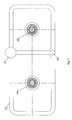
- the present embodiment provides a structure which allows the swing arm and the connecting cable to connect with each other very conveniently and fast.
- the connecting cable 101 is provided with a joint ball 200 at its end tha is supposed to be connected to the swing arm.
- Said free end of the swing arm has a special locating hole 201 for placing said joint ball; in additon, said free end has a sliding block 202 for fixing the joint ball inside the locating hole.
- the numerical designator 203 represents a sliding groove for the sliding block 202.
- the sliding block is provided with an operating button 204.
- the sliding block can do circumferential motion.
- Said free end of the swing arm has two locating slots, 205 and 206, and a spring 207 for acting on the sliding block.
- the numerical designator 208 represents the spring seat.
- the operating button 204 is set by hand to make the sliding block move back.
- the sliding block makes room for the locating hole 201; by slightly turning the operating button and in turn the sliding block, the operating button is moved to the locating slot 205 so as to be further located, and accordingly it becomes easy to put the joint ball 200 into the locating hole 201, which is shown in Fig.7 .
- the sliding block By turning the operating button and in turn moving the sliding block again in order to move the operating button 204 out of the locating slot 205, the sliding block is going to move forward under the action of the spring 207; when the operating button goes to the locating slot 206, the sliding block will lock the joint ball 200 into the locating hole 201; next, by fine-tuning the operating button 204 and in turn slightly moving the sliding block, the operating button will be located in the locating slot 206, and therefore the connection between the swing arm and the connecting cable will be more reliable and stable, which state is shown in Fig. 8 .
- Said connecting cable can be an entire steel cable or comprise of several connected steel cables.
- Said connecting cable can be provided with a guidance mating member 101 a for moving back and forth. This guidance mating member can cooperate with a guidance pipe 104 disposed in or out of the present device in order to guide the movement of the cable.
- a sealing ring 104a is set around the surface of the guidance mating member 101a for sealing the guidance mating member 101a from the guidance pipe 104.
- 105 is a screw cap connected with the guidance pipe 104.
- Said connecting cable might connect direct with the open/close controller and the open/close function mechanism of the plug mechanism of a washing tank system, or connect via other connecting parts.
- a split nut 33 is used to connect the head of one end of the connecting cable to the head 21 of the sliding shaft.
- a rubber pad 330 is mounted at the top of the split nut 33 for shock absorption.
- the other end of the connecting cable is connected to the free end of the swing arm via grooves on the connecting member 102b connected with the swing arm and via corresponding grooves on the swing arm.
- the numerical designator 101c is a plastic sleeve covering the connecting cable.
- 106 is an adjusting screw between the the plastic sleeve 101c and the spring installation sleeve 32 of a fixed sleeve.
- the adjusting screw is connected with the spring installation sleeve 32, and is used for fine tuning the length of the cable.
- the numerical designator 107 is a locknut connected via thread with the adjusting screw 106 and acts for tightening the adjusting screw.
- Said fixed sleeve includes a guide sleeve 31 and the spring installation sleeve 32 which is connected with the bottom of the guide sleeve.
- Said spring 4 is installed inside the spring installation sleeve 32 and, with the bulge in the spring installation sleeve as a support, holds upward the head of the sliding shaft.
- the spring 4 can be set inside the guide sleeve 31 and holds upward other parts of the sliding shaft or holds the button.
- the spring can also be set outside all these sleeves mentioned above or put in any parts positioned in a proper place of the washing tank, as long as the sliding shaft can receive a force in the direction from the head to the end.
- the connecting component 34 is connected via thread with the guide sleeve and is passed through by the sliding shaft.
- the sliding shaft has a locating groove 22 along its axis direction, and correspondingly there is a circumferential location mechanism in the open/close device matching the locating groove, which is a locating raised part 35 on the connecting component.
- the locating groove can also be set on the fixed sleeve, and then the locating raised part is set in a corresponding place of the sliding haft.
- the circumferential location mechanism can adopt other forms used between the shaft and the sleeve.
- Said open/close controller is provided with a retaining hook 6 for the sliding shaft; the retaining hook is connected to the locating raised part of said connecting component; therefore, the shape of the raised part can be utilized to match the retaining hook.
- a coil spring 36 provided outside the connecting component for fixing the retaining hook.
- the retaining hook can also be connected to the fixed sleeve or other fixed parts inside or outside the present device.
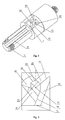
- first stop position 71 and second stop position 72 set on the surface of the sliding shaft, which is movably engaged with the hook part 60 of the retaining hook 6.
- the first stop position and second stop position is respectively configurated at a different height of the surface of the sliding shaft, with the first stop position being closer to the head 21 of the sliding shaft than the second stop position.
- a first one-way slideway is set on the surface of the sliding shaft that allows the sliding shaft to move from the point where the first stop position is movably engaged with the hook part of the retaining hook 60 to the point where the second stop position is movably engaged with the hook part.
- a second one-way slideway is also set on the surface of the sliding shaft that allows the sliding shaft to move from the point where the second stop position is movably engaged with the hook part of the retaining hook to the point, where the first stop position is movably engaged with the hook part.
- Said first one-way slideway includes a first section of slideway 81 starting from the first stop position and a second section of slideway 82 connecting with the first section of slideway and leading to the second stop position, the connecting area being farther from the head of the sliding shaft than the second stop position;
- said second one-way slideway includes a third section 83 of slideway starting from the second stop position and a fourth section 84 of slideway connecting with the third section of slideway, the connecting area being farther from the head of the sliding shaft than the second stop position; said fourth section of slideway is connected through the first section of slideway or connected to the first stop position.
- the first section of sideway 81 and the second section of sideway 82 connect with each other in a stepped manner, specifically at the joint 91; the bottom of the second section of slideway is lower than the bottom of the first section of slideway; the third section of slideway 83 and the fourth section of slideway 84 connect with each other in a stepped manner, specifically at the joint 92; the bottom of the fourth section of slideway is lower than the bottom of the third section of slideway; the second section of slideway has a downward step 93 at the place near to the second stop position; the fourth section slideway and the first section of slideway connect with each other in a stepped manner, specifically at the joint 94; the bottom of the first section of slideway is lower than the bottom of the fourth section of slideway
- the retaining hook can be movably engaged with the slideway of the sliding shaft.
- the sliding shaft can also be rotated at a certain angle in order to be movably engaged with the the retaining hook, but which is less convenient than the former.
- the button in virtue of the applied force of the spring 4, will make the sliding shaft move upward; however, because the first section of slideway and the second section of slideway connect through steps at joint 91, and the bottom of the second section of slideway is lower than the bottom of the first section of slideway, therefore the retaining hook is not able to backtrack, but only can go down along the second section of sideway to the second stop position area and further hook with the exact stop point of the second stop position, and accordingly fulfil the downward journey of the sliding shaft; at the same moment, the spring 4 is in a compressed state, which means the washing tank is in a water storing status and is illustrated in the left switch of Fig. 1 and Fig.2 . At that point, the connecting cable 101 stops pulling the swing arm 102, and then the swing arm rotates clockwise to get out of the ascending-descending guidance shaft 100b, and consequently the washing tank drain system gets into a closed state.
- the force acted by the spring 4 causes the sliding shaft 2 to move upward; since the third and fourth section of slideway connect through steps at joint 92, and the bottom of the fourth is lower than the third one, the retaining hook is not able to backtrack, but can only goes downward along the fourth section of slideway to the first stop position, or goes downward along the fourth section of slideway in order to get into the first section of slideway and finally goes back to the first stop position and further hook with the first stop position, which means that the sliding shatf has finished the entire upward journey and the open/close controller has started the other status that is illustrated in the right open/close controller of Fig.1 and Fig.2 .
- the connecting cable is tightening the swing arm, as illustrated in the left open/close controller of Fig.1 and Fig.2 , and further causes the swing arm to rotate counterclockwise so as to lift the ascending-descending guidance shaft 100 up; therefore, the washing tank drain system gets into a open state.
Landscapes
- Engineering & Computer Science (AREA)
- Mechanical Engineering (AREA)
- Environmental & Geological Engineering (AREA)
- Health & Medical Sciences (AREA)
- Life Sciences & Earth Sciences (AREA)
- Hydrology & Water Resources (AREA)
- Public Health (AREA)
- Water Supply & Treatment (AREA)
- Sink And Installation For Waste Water (AREA)
Applications Claiming Priority (2)
| Application Number | Priority Date | Filing Date | Title |
|---|---|---|---|
| CN2008100591025A CN101215848B (zh) | 2008-01-10 | 2008-01-10 | 一种洗槽下水的开关装置 |
| PCT/CN2008/073897 WO2009089767A1 (fr) | 2008-01-10 | 2008-12-31 | Dispositif de commutation pour extraire de l'eau d'un bac de lavage |
Publications (3)
| Publication Number | Publication Date |
|---|---|
| EP2243885A1 true EP2243885A1 (fr) | 2010-10-27 |
| EP2243885A4 EP2243885A4 (fr) | 2016-03-02 |
| EP2243885B1 EP2243885B1 (fr) | 2017-11-29 |
Family
ID=39622352
Family Applications (1)
| Application Number | Title | Priority Date | Filing Date |
|---|---|---|---|
| EP08871131.2A Active EP2243885B1 (fr) | 2008-01-10 | 2008-12-31 | Dispositif de commutation pour extraction de l'eau d'un bac de lavage |
Country Status (4)
| Country | Link |
|---|---|
| US (1) | US8468619B2 (fr) |
| EP (1) | EP2243885B1 (fr) |
| CN (1) | CN101215848B (fr) |
| WO (1) | WO2009089767A1 (fr) |
Families Citing this family (7)
| Publication number | Priority date | Publication date | Assignee | Title |
|---|---|---|---|---|
| CN101215848B (zh) * | 2008-01-10 | 2010-06-09 | 宁波搏盛阀门管件有限公司 | 一种洗槽下水的开关装置 |
| US9181686B2 (en) * | 2011-08-18 | 2015-11-10 | Kohler Co. | Replaceable trim kit |
| CN107188248B (zh) * | 2017-07-04 | 2018-06-26 | 江苏和顺布业有限公司 | 一种污水处理装置 |
| WO2019061210A1 (fr) * | 2017-09-29 | 2019-04-04 | 赵锦成 | Évier |
| CN110820875A (zh) * | 2018-08-07 | 2020-02-21 | 宁波搏盛阀门管件有限公司 | 安装方便的按压式台控及下水装置 |
| CN111851665A (zh) * | 2019-04-30 | 2020-10-30 | 宁波搏盛阀门管件有限公司 | 厨卫设施快简安装的连接机构及厨卫设施 |
| US10858813B1 (en) | 2020-04-20 | 2020-12-08 | Brent F. Nelson | Drain stopper apparatus |
Family Cites Families (21)
| Publication number | Priority date | Publication date | Assignee | Title |
|---|---|---|---|---|
| US3002196A (en) * | 1959-09-29 | 1961-10-03 | Scovill Manufacturing Co | Pop-up drain valve |
| AT317097B (de) * | 1971-10-18 | 1974-08-12 | Hutterer & Lechner Kg | Vorrichtung zum Öffnen und Schließen eines Verschlusses, insbesondere des Verschlußstopfens von Badewannen, Waschmuscheln u.dgl. |
| US4596057A (en) * | 1984-01-31 | 1986-06-24 | Ikumi Ohta | Draining plug device |
| JPH01119132U (fr) * | 1988-02-08 | 1989-08-11 | ||
| WO1996032044A1 (fr) * | 1995-04-11 | 1996-10-17 | Wes Wastes Limited | Bonde actionnee a distance |
| JP3538495B2 (ja) * | 1996-01-30 | 2004-06-14 | 育實 太田 | 排水栓装置 |
| JPH09209429A (ja) * | 1996-02-01 | 1997-08-12 | Toto Ltd | 浴槽等における排水栓構造 |
| US5822812A (en) * | 1996-06-19 | 1998-10-20 | Wes Wastes Limited | Remote operated plug |
| JPH11193561A (ja) * | 1997-12-26 | 1999-07-21 | Maruichi Kk | 水槽の遠隔操作式排水栓開閉装置 |
| JP3051977B2 (ja) * | 1997-12-29 | 2000-06-12 | 丸一株式会社 | 排水栓部の栓蓋の開閉装置 |
| US6023795A (en) * | 1998-04-09 | 2000-02-15 | Evac International Oy | Washbasin drain assembly |
| US6973685B2 (en) * | 2001-01-24 | 2005-12-13 | Scott Duncan | Bladder stopper and control assembly |
| CN1218094C (zh) * | 2002-12-30 | 2005-09-07 | 汤米及布雷恩公司 | 远程操作式排水栓装置 |
| DE10333658A1 (de) * | 2003-07-24 | 2005-03-10 | Blanco Gmbh & Co Kg | Bewegungseinrichtung zum Bewegen eines Verschlußelements zum Verschließen einer Abflußöffnung |
| KR100632446B1 (ko) * | 2004-01-20 | 2006-10-13 | 장충삼 | 세면기의 팝업밸브 개폐장치 |
| US7886372B2 (en) * | 2005-02-11 | 2011-02-15 | As Ip Holdco, L.L.C. | Drain assembly for rapid installation in sanitary vessels |
| CN2825766Y (zh) * | 2005-09-29 | 2006-10-11 | 方家宝 | 水槽去水启闭装置 |
| CN1746441A (zh) * | 2005-09-29 | 2006-03-15 | 方家宝 | 水槽去水启闭装置 |
| US20090158522A1 (en) * | 2007-12-19 | 2009-06-25 | Chao-Chung Wu | Drain plug assembly |
| CN201198590Y (zh) * | 2008-01-10 | 2009-02-25 | 宁波搏盛阀门管件有限公司 | 一种洗槽下水的开关装置 |
| CN101215848B (zh) * | 2008-01-10 | 2010-06-09 | 宁波搏盛阀门管件有限公司 | 一种洗槽下水的开关装置 |
-
2008
- 2008-01-10 CN CN2008100591025A patent/CN101215848B/zh active Active
- 2008-12-31 EP EP08871131.2A patent/EP2243885B1/fr active Active
- 2008-12-31 US US12/811,825 patent/US8468619B2/en not_active Expired - Fee Related
- 2008-12-31 WO PCT/CN2008/073897 patent/WO2009089767A1/fr not_active Ceased
Non-Patent Citations (1)
| Title |
|---|
| See references of WO2009089767A1 * |
Also Published As
| Publication number | Publication date |
|---|---|
| US20100282995A1 (en) | 2010-11-11 |
| EP2243885B1 (fr) | 2017-11-29 |
| EP2243885A4 (fr) | 2016-03-02 |
| US8468619B2 (en) | 2013-06-25 |
| CN101215848A (zh) | 2008-07-09 |
| WO2009089767A1 (fr) | 2009-07-23 |
| CN101215848B (zh) | 2010-06-09 |
Similar Documents
| Publication | Publication Date | Title |
|---|---|---|
| EP2243885A1 (fr) | Dispositif de commutation pour extraire de l'eau d'un bac de lavage | |
| US10683685B2 (en) | Reciprocating device | |
| CN105015519B (zh) | 车辆的驻车锁定解除装置 | |
| US5180198A (en) | Motor driven lock device for trunk lid and the like | |
| US20110290050A1 (en) | Adjusting device having a spindle drive | |
| US10526823B2 (en) | Vehicle door latching device | |
| JP2010534900A (ja) | キッチン・バス用スイッチ | |
| JP2020094330A (ja) | ローラユニット | |
| JP2001507418A (ja) | ガイドレールを備えたケーブル式窓リフタ | |
| JPWO2014045338A1 (ja) | 車両用ルーフ装置 | |
| CN110801317B (zh) | 一种具有手肘关节装置的义肢 | |
| US20030226235A1 (en) | Door hold and release mechanism | |
| JP2002122271A (ja) | ケーブル固定用のワンタッチキャップ | |
| KR20220007285A (ko) | 양변기의 자동과 수동 겸용 물내림 장치 | |
| US11162286B2 (en) | Closing device for a storage compartment, storage compartment for a motor vehicle | |
| JP4950905B2 (ja) | ドアーロック機構 | |
| JPH10168973A (ja) | 水槽の遠隔操作式排水栓開閉装置 | |
| KR101642835B1 (ko) | 수동식 차량시트 고정장치 | |
| CN201198590Y (zh) | 一种洗槽下水的开关装置 | |
| KR101106539B1 (ko) | 세면대용 배수장치 | |
| JP5849714B2 (ja) | 遠隔操作式排水栓装置 | |
| JP4028042B2 (ja) | 車両用コーナポール装置 | |
| JP2019027171A (ja) | ベルクランク装置及びベルクランクユニット | |
| KR100348053B1 (ko) | 자동차용 주차 브레이크장치 | |
| JP2005307446A (ja) | アウトサイドハンドルとドアラッチとの結合構造 |
Legal Events
| Date | Code | Title | Description |
|---|---|---|---|
| PUAI | Public reference made under article 153(3) epc to a published international application that has entered the european phase |
Free format text: ORIGINAL CODE: 0009012 |
|
| 17P | Request for examination filed |
Effective date: 20100809 |
|
| AK | Designated contracting states |
Kind code of ref document: A1 Designated state(s): AT BE BG CH CY CZ DE DK EE ES FI FR GB GR HR HU IE IS IT LI LT LU LV MC MT NL NO PL PT RO SE SI SK TR |
|
| AX | Request for extension of the european patent |
Extension state: AL BA MK RS |
|
| DAX | Request for extension of the european patent (deleted) | ||
| RIC1 | Information provided on ipc code assigned before grant |
Ipc: E03C 1/23 20060101AFI20150724BHEP |
|
| RIC1 | Information provided on ipc code assigned before grant |
Ipc: E03C 1/23 20060101AFI20151001BHEP |
|
| RIC1 | Information provided on ipc code assigned before grant |
Ipc: E03C 1/23 20060101AFI20151008BHEP |
|
| RA4 | Supplementary search report drawn up and despatched (corrected) |
Effective date: 20160203 |
|
| RIC1 | Information provided on ipc code assigned before grant |
Ipc: E03C 1/23 20060101AFI20160128BHEP |
|
| GRAP | Despatch of communication of intention to grant a patent |
Free format text: ORIGINAL CODE: EPIDOSNIGR1 |
|
| STAA | Information on the status of an ep patent application or granted ep patent |
Free format text: STATUS: GRANT OF PATENT IS INTENDED |
|
| INTG | Intention to grant announced |
Effective date: 20170707 |
|
| GRAS | Grant fee paid |
Free format text: ORIGINAL CODE: EPIDOSNIGR3 |
|
| GRAA | (expected) grant |
Free format text: ORIGINAL CODE: 0009210 |
|
| STAA | Information on the status of an ep patent application or granted ep patent |
Free format text: STATUS: THE PATENT HAS BEEN GRANTED |
|
| AK | Designated contracting states |
Kind code of ref document: B1 Designated state(s): AT BE BG CH CY CZ DE DK EE ES FI FR GB GR HR HU IE IS IT LI LT LU LV MC MT NL NO PL PT RO SE SI SK TR |
|
| REG | Reference to a national code |
Ref country code: GB Ref legal event code: FG4D |
|
| REG | Reference to a national code |
Ref country code: CH Ref legal event code: EP |
|
| REG | Reference to a national code |
Ref country code: AT Ref legal event code: REF Ref document number: 950530 Country of ref document: AT Kind code of ref document: T Effective date: 20171215 |
|
| REG | Reference to a national code |
Ref country code: IE Ref legal event code: FG4D |
|
| REG | Reference to a national code |
Ref country code: DE Ref legal event code: R096 Ref document number: 602008053205 Country of ref document: DE |
|
| REG | Reference to a national code |
Ref country code: NL Ref legal event code: MP Effective date: 20171129 |
|
| REG | Reference to a national code |
Ref country code: LT Ref legal event code: MG4D |
|
| REG | Reference to a national code |
Ref country code: AT Ref legal event code: MK05 Ref document number: 950530 Country of ref document: AT Kind code of ref document: T Effective date: 20171129 |
|
| PG25 | Lapsed in a contracting state [announced via postgrant information from national office to epo] |
Ref country code: SE Free format text: LAPSE BECAUSE OF FAILURE TO SUBMIT A TRANSLATION OF THE DESCRIPTION OR TO PAY THE FEE WITHIN THE PRESCRIBED TIME-LIMIT Effective date: 20171129 Ref country code: NO Free format text: LAPSE BECAUSE OF FAILURE TO SUBMIT A TRANSLATION OF THE DESCRIPTION OR TO PAY THE FEE WITHIN THE PRESCRIBED TIME-LIMIT Effective date: 20180228 Ref country code: ES Free format text: LAPSE BECAUSE OF FAILURE TO SUBMIT A TRANSLATION OF THE DESCRIPTION OR TO PAY THE FEE WITHIN THE PRESCRIBED TIME-LIMIT Effective date: 20171129 Ref country code: LT Free format text: LAPSE BECAUSE OF FAILURE TO SUBMIT A TRANSLATION OF THE DESCRIPTION OR TO PAY THE FEE WITHIN THE PRESCRIBED TIME-LIMIT Effective date: 20171129 Ref country code: FI Free format text: LAPSE BECAUSE OF FAILURE TO SUBMIT A TRANSLATION OF THE DESCRIPTION OR TO PAY THE FEE WITHIN THE PRESCRIBED TIME-LIMIT Effective date: 20171129 |
|
| PG25 | Lapsed in a contracting state [announced via postgrant information from national office to epo] |
Ref country code: BG Free format text: LAPSE BECAUSE OF FAILURE TO SUBMIT A TRANSLATION OF THE DESCRIPTION OR TO PAY THE FEE WITHIN THE PRESCRIBED TIME-LIMIT Effective date: 20180228 Ref country code: LV Free format text: LAPSE BECAUSE OF FAILURE TO SUBMIT A TRANSLATION OF THE DESCRIPTION OR TO PAY THE FEE WITHIN THE PRESCRIBED TIME-LIMIT Effective date: 20171129 Ref country code: AT Free format text: LAPSE BECAUSE OF FAILURE TO SUBMIT A TRANSLATION OF THE DESCRIPTION OR TO PAY THE FEE WITHIN THE PRESCRIBED TIME-LIMIT Effective date: 20171129 Ref country code: HR Free format text: LAPSE BECAUSE OF FAILURE TO SUBMIT A TRANSLATION OF THE DESCRIPTION OR TO PAY THE FEE WITHIN THE PRESCRIBED TIME-LIMIT Effective date: 20171129 Ref country code: GR Free format text: LAPSE BECAUSE OF FAILURE TO SUBMIT A TRANSLATION OF THE DESCRIPTION OR TO PAY THE FEE WITHIN THE PRESCRIBED TIME-LIMIT Effective date: 20180301 |
|
| PG25 | Lapsed in a contracting state [announced via postgrant information from national office to epo] |
Ref country code: NL Free format text: LAPSE BECAUSE OF FAILURE TO SUBMIT A TRANSLATION OF THE DESCRIPTION OR TO PAY THE FEE WITHIN THE PRESCRIBED TIME-LIMIT Effective date: 20171129 |
|
| PG25 | Lapsed in a contracting state [announced via postgrant information from national office to epo] |
Ref country code: EE Free format text: LAPSE BECAUSE OF FAILURE TO SUBMIT A TRANSLATION OF THE DESCRIPTION OR TO PAY THE FEE WITHIN THE PRESCRIBED TIME-LIMIT Effective date: 20171129 Ref country code: DK Free format text: LAPSE BECAUSE OF FAILURE TO SUBMIT A TRANSLATION OF THE DESCRIPTION OR TO PAY THE FEE WITHIN THE PRESCRIBED TIME-LIMIT Effective date: 20171129 Ref country code: SK Free format text: LAPSE BECAUSE OF FAILURE TO SUBMIT A TRANSLATION OF THE DESCRIPTION OR TO PAY THE FEE WITHIN THE PRESCRIBED TIME-LIMIT Effective date: 20171129 Ref country code: CZ Free format text: LAPSE BECAUSE OF FAILURE TO SUBMIT A TRANSLATION OF THE DESCRIPTION OR TO PAY THE FEE WITHIN THE PRESCRIBED TIME-LIMIT Effective date: 20171129 Ref country code: CY Free format text: LAPSE BECAUSE OF FAILURE TO SUBMIT A TRANSLATION OF THE DESCRIPTION OR TO PAY THE FEE WITHIN THE PRESCRIBED TIME-LIMIT Effective date: 20171129 |
|
| REG | Reference to a national code |
Ref country code: CH Ref legal event code: PL |
|
| REG | Reference to a national code |
Ref country code: DE Ref legal event code: R097 Ref document number: 602008053205 Country of ref document: DE |
|
| PG25 | Lapsed in a contracting state [announced via postgrant information from national office to epo] |
Ref country code: PL Free format text: LAPSE BECAUSE OF FAILURE TO SUBMIT A TRANSLATION OF THE DESCRIPTION OR TO PAY THE FEE WITHIN THE PRESCRIBED TIME-LIMIT Effective date: 20171129 Ref country code: RO Free format text: LAPSE BECAUSE OF FAILURE TO SUBMIT A TRANSLATION OF THE DESCRIPTION OR TO PAY THE FEE WITHIN THE PRESCRIBED TIME-LIMIT Effective date: 20171129 |
|
| PG25 | Lapsed in a contracting state [announced via postgrant information from national office to epo] |
Ref country code: MT Free format text: LAPSE BECAUSE OF NON-PAYMENT OF DUE FEES Effective date: 20171231 Ref country code: LU Free format text: LAPSE BECAUSE OF NON-PAYMENT OF DUE FEES Effective date: 20171231 |
|
| REG | Reference to a national code |
Ref country code: IE Ref legal event code: MM4A |
|
| PLBE | No opposition filed within time limit |
Free format text: ORIGINAL CODE: 0009261 |
|
| STAA | Information on the status of an ep patent application or granted ep patent |
Free format text: STATUS: NO OPPOSITION FILED WITHIN TIME LIMIT |
|
| REG | Reference to a national code |
Ref country code: BE Ref legal event code: MM Effective date: 20171231 |
|
| PG25 | Lapsed in a contracting state [announced via postgrant information from national office to epo] |
Ref country code: IE Free format text: LAPSE BECAUSE OF NON-PAYMENT OF DUE FEES Effective date: 20171231 |
|
| 26N | No opposition filed |
Effective date: 20180830 |
|
| REG | Reference to a national code |
Ref country code: FR Ref legal event code: ST Effective date: 20181024 |
|
| PG25 | Lapsed in a contracting state [announced via postgrant information from national office to epo] |
Ref country code: CH Free format text: LAPSE BECAUSE OF NON-PAYMENT OF DUE FEES Effective date: 20171231 Ref country code: LI Free format text: LAPSE BECAUSE OF NON-PAYMENT OF DUE FEES Effective date: 20171231 Ref country code: SI Free format text: LAPSE BECAUSE OF FAILURE TO SUBMIT A TRANSLATION OF THE DESCRIPTION OR TO PAY THE FEE WITHIN THE PRESCRIBED TIME-LIMIT Effective date: 20171129 Ref country code: BE Free format text: LAPSE BECAUSE OF NON-PAYMENT OF DUE FEES Effective date: 20171231 |
|
| PG25 | Lapsed in a contracting state [announced via postgrant information from national office to epo] |
Ref country code: FR Free format text: LAPSE BECAUSE OF NON-PAYMENT OF DUE FEES Effective date: 20180129 |
|
| PG25 | Lapsed in a contracting state [announced via postgrant information from national office to epo] |
Ref country code: HU Free format text: LAPSE BECAUSE OF FAILURE TO SUBMIT A TRANSLATION OF THE DESCRIPTION OR TO PAY THE FEE WITHIN THE PRESCRIBED TIME-LIMIT; INVALID AB INITIO Effective date: 20081231 Ref country code: MC Free format text: LAPSE BECAUSE OF FAILURE TO SUBMIT A TRANSLATION OF THE DESCRIPTION OR TO PAY THE FEE WITHIN THE PRESCRIBED TIME-LIMIT Effective date: 20171129 |
|
| PG25 | Lapsed in a contracting state [announced via postgrant information from national office to epo] |
Ref country code: TR Free format text: LAPSE BECAUSE OF FAILURE TO SUBMIT A TRANSLATION OF THE DESCRIPTION OR TO PAY THE FEE WITHIN THE PRESCRIBED TIME-LIMIT Effective date: 20171129 |
|
| PG25 | Lapsed in a contracting state [announced via postgrant information from national office to epo] |
Ref country code: PT Free format text: LAPSE BECAUSE OF FAILURE TO SUBMIT A TRANSLATION OF THE DESCRIPTION OR TO PAY THE FEE WITHIN THE PRESCRIBED TIME-LIMIT Effective date: 20171129 |
|
| PG25 | Lapsed in a contracting state [announced via postgrant information from national office to epo] |
Ref country code: IS Free format text: LAPSE BECAUSE OF FAILURE TO SUBMIT A TRANSLATION OF THE DESCRIPTION OR TO PAY THE FEE WITHIN THE PRESCRIBED TIME-LIMIT Effective date: 20180329 |
|
| REG | Reference to a national code |
Ref country code: DE Ref legal event code: R082 Ref document number: 602008053205 Country of ref document: DE Representative=s name: HL KEMPNER PATENTANWAELTE, SOLICITORS (ENGLAND, DE Ref country code: DE Ref legal event code: R082 Ref document number: 602008053205 Country of ref document: DE Representative=s name: HL KEMPNER PATENTANWALT, RECHTSANWALT, SOLICIT, DE Ref country code: DE Ref legal event code: R082 Ref document number: 602008053205 Country of ref document: DE Representative=s name: HL KEMPNER PARTG MBB, DE |
|
| PGFP | Annual fee paid to national office [announced via postgrant information from national office to epo] |
Ref country code: IT Payment date: 20221228 Year of fee payment: 15 |
|
| PG25 | Lapsed in a contracting state [announced via postgrant information from national office to epo] |
Ref country code: IT Free format text: LAPSE BECAUSE OF NON-PAYMENT OF DUE FEES Effective date: 20231231 |
|
| PGFP | Annual fee paid to national office [announced via postgrant information from national office to epo] |
Ref country code: DE Payment date: 20251215 Year of fee payment: 18 |
|
| PGFP | Annual fee paid to national office [announced via postgrant information from national office to epo] |
Ref country code: GB Payment date: 20251216 Year of fee payment: 18 |