EP2244021A2 - Heiz- und Kühleinheit sowie Heiz- und Kühlvorrichtung - Google Patents
Heiz- und Kühleinheit sowie Heiz- und Kühlvorrichtung Download PDFInfo
- Publication number
- EP2244021A2 EP2244021A2 EP10159485A EP10159485A EP2244021A2 EP 2244021 A2 EP2244021 A2 EP 2244021A2 EP 10159485 A EP10159485 A EP 10159485A EP 10159485 A EP10159485 A EP 10159485A EP 2244021 A2 EP2244021 A2 EP 2244021A2
- Authority
- EP
- European Patent Office
- Prior art keywords
- air
- heating
- room inside
- cooling unit
- heat
- Prior art date
- Legal status (The legal status is an assumption and is not a legal conclusion. Google has not performed a legal analysis and makes no representation as to the accuracy of the status listed.)
- Granted
Links
Images


Classifications
-
- F—MECHANICAL ENGINEERING; LIGHTING; HEATING; WEAPONS; BLASTING
- F24—HEATING; RANGES; VENTILATING
- F24F—AIR-CONDITIONING; AIR-HUMIDIFICATION; VENTILATION; USE OF AIR CURRENTS FOR SCREENING
- F24F1/00—Room units for air-conditioning, e.g. separate or self-contained units or units receiving primary air from a central station
- F24F1/0007—Indoor units, e.g. fan coil units
- F24F1/00075—Indoor units, e.g. fan coil units receiving air from a central station
-
- F—MECHANICAL ENGINEERING; LIGHTING; HEATING; WEAPONS; BLASTING
- F24—HEATING; RANGES; VENTILATING
- F24F—AIR-CONDITIONING; AIR-HUMIDIFICATION; VENTILATION; USE OF AIR CURRENTS FOR SCREENING
- F24F1/00—Room units for air-conditioning, e.g. separate or self-contained units or units receiving primary air from a central station
- F24F1/01—Room units for air-conditioning, e.g. separate or self-contained units or units receiving primary air from a central station in which secondary air is induced by injector action of the primary air
-
- F—MECHANICAL ENGINEERING; LIGHTING; HEATING; WEAPONS; BLASTING
- F24—HEATING; RANGES; VENTILATING
- F24F—AIR-CONDITIONING; AIR-HUMIDIFICATION; VENTILATION; USE OF AIR CURRENTS FOR SCREENING
- F24F13/00—Details common to, or for air-conditioning, air-humidification, ventilation or use of air currents for screening
- F24F13/02—Ducting arrangements
- F24F13/06—Outlets for directing or distributing air into rooms or spaces, e.g. ceiling air diffuser
- F24F13/078—Outlets for directing or distributing air into rooms or spaces, e.g. ceiling air diffuser combined with lighting fixtures
-
- F—MECHANICAL ENGINEERING; LIGHTING; HEATING; WEAPONS; BLASTING
- F24—HEATING; RANGES; VENTILATING
- F24F—AIR-CONDITIONING; AIR-HUMIDIFICATION; VENTILATION; USE OF AIR CURRENTS FOR SCREENING
- F24F5/00—Air-conditioning systems or apparatus not covered by F24F1/00 or F24F3/00, e.g. using solar heat or combined with household units such as an oven or water heater
- F24F5/0089—Systems using radiation from walls or panels
- F24F5/0092—Systems using radiation from walls or panels ceilings, e.g. cool ceilings
-
- F—MECHANICAL ENGINEERING; LIGHTING; HEATING; WEAPONS; BLASTING
- F24—HEATING; RANGES; VENTILATING
- F24F—AIR-CONDITIONING; AIR-HUMIDIFICATION; VENTILATION; USE OF AIR CURRENTS FOR SCREENING
- F24F2221/00—Details or features not otherwise provided for
- F24F2221/14—Details or features not otherwise provided for mounted on the ceiling
Definitions
- the present invention relates to a heating and cooling unit and a heating and cooling apparatus for adjusting the temperature of feed air to be fed and supplying air to the room inside.
- a heating and cooling apparatus for carrying out comfortable heating and cooling by, for example, burying a heating and cooling unit provided with a radiation panel, in which a plurality of pipes for letting heating medium or cooling medium through are installed, in the ceiling and carrying out radiation heating or radiation cooling is in widespread use instead of a conventional heating and cooling apparatus (e.g., a multi air conditioner or a fan coil unit) for blowing cold air or warm air directly to the room inside.
- a conventional heating and cooling apparatus e.g., a multi air conditioner or a fan coil unit
- Patent Literature 1 a ceiling heating-cooling radiation panel comprising: a pipe support part, which is formed to be integrated with a radiation panel body and in which a pipe for letting temperature medium through can be fitted from the thickness direction of the radiation panel body; and a pipe screw member, which is engaged with the pipe support part to fix the pipe for letting temperature medium through, whereby attachment of the pipe for letting temperature medium through can be facilitated and replacement of the pipe for letting temperature medium through can be carried out easily even after installation thereof. (refer to Japanese Patent Application Laid-Open No. H7-19533 (1995 )).
- a heating and cooling apparatus such as a multi air conditioner or a fan coil unit described above has a problem that the wind velocity of cold air or warm air from an indoor equipment installed at the room inside is too high, and causes the user of the room inside to feel a draft and tends to cause temperature unevenness at the room inside.
- the air conditioning efficiency of the heating and cooling apparatus described above which uses radiation cooling or radiation heating, is low since only low heat or high heat due to radiation cooling or radiation heating is employed therein, and the range of use of the heating and cooling apparatus is limited. For example, it is not appropriate to use the heating and cooling apparatus in a place having poor thermal insulation properties, a place having a large thermal load, or a place having much air flowing into and out thereof. Moreover, there is another problem that it is necessary to provide measures against dew condensation or the like separately, which causes cost increase.
- the present invention has been made in view of such a situation, and an object thereof is to provide a heating and cooling unit and a heating and cooling apparatus in which since supplying mixed air which is obtained by mixing feed air to be fed and circulated air from the room inside, to the room inside in a laminar manner, and emitting heat obtaining from the mixed air, to the room inside so as to carry out an air conditioning of the room inside, it becomes to possible to get high efficiency and high power, to reduce a space unsuitable for air conditioning than air conditioning by the conventional radiation panel employing only heat emission , to prevent a draft and temperature unevenness, to expand the range of usage of the apparatus, and to avoid the need of a measures against dew condensation.
- a heating and cooling unit is characterized by comprising: a mixer case for supplying mixed air, which is obtained by mixing circulated air from the room inside with feed air to be fed, to the room inside; a guide path, which is communicatively connected with the circulated air, for guiding the feed air to the mixer case; and a heat storage radiation member, which is attached in the mixer case in a thermally-conductive manner, for obtaining heat from the mixed air and radiating the heat to the room inside.
- feed air to be fed is blown through the guide path to the mixer case.
- the circulated air flows through the guide path into the mixer case and is mixed with the feed air to become mixed air.
- the heat storage radiation member obtains low heat or high heat from the mixed air and carries out radiation cooling or radiation heating to the room inside.
- a heating and cooling unit is characterized by comprising: an adjustment case for adjusting the flow of the feed air; and a box member, which has an opening at one face thereof and is buried in a wall at the room inside with said one face facing the room inside, for housing the adjustment case, the mixer case and the guide path, wherein a circulated air path communicatively connecting from the opening to the guide path is formed inside said box member.
- the box member houses therein the adjustment case, the mixer case and the guide path, and the circulated air path is further formed. Circulated air enters the box member via the opening, travels through the circulated air path and the guide path, and flows into the mixer case.
- a heating and cooling unit is characterized in that the heat storage radiation member comprises a plurality of juxtaposed flow dividing fins for dividing the flow of mixed air to be supplied to the room inside and letting the mixed air through.
- the flow of mixed air to be supplied to the room inside is divided into a plurality of layers by the flow dividing fins of the heat storage radiation member, and the mixed air is supplied to the room inside in a so-called multi-layer flow manner, and therefore the draft to be given to the user of the room inside is suppressed.
- a heating and cooling unit is characterized in that the heat storage radiation member comprises an elliptical heat storage pipe penetrating the plurality of flow dividing fins in a juxtaposition direction of the flow dividing fins.
- the heat storage pipe since the heat storage pipe has an elliptical shape, a pressure loss to be caused by collision between the mixed air and the heat storage pipe while the mixed air passes the heat storage radiation member and is fed to the room inside can be reduced, and the mixed air passes the heat storage radiation member smoothly and is supplied to the room inside. Moreover, the heat storage pipe strengthens the flow dividing fins and radiates heat, which is obtained from the mixed air and stored, to the room inside.
- a heating and cooling unit is characterized by comprising a plurality of short tubular protrusions, which are formed to protrude from a face of the flow dividing fins, for changing the direction of radiation heating toward the room inside and dividing the flow of the mixed air.
- the short tubular protrusions change the direction of radiation heating toward the room inside and further divide the flow of mixed air to be supplied to the room inside. Moreover, since the protrusions come into contact with the mixed air at this time, heat is obtained from the mixed air and transferred not only by the flow dividing fins but also by the protrusions more uniformly over the entire area of the heat storage radiation member, and occurrence of temperature unevenness in radiation heating to the room inside and in supply of mixed air is inhibited.
- a heating and cooling unit is characterized in that the protrusions are juxtaposed in the longitudinal direction of the flow dividing fins so as to reach or almost reach adjacent flow dividing fins, the mixer case comprises an aperture face, which has an aperture where mixed air to be supplied to the room inside passes and faces said room inside, and the aperture is positioned below the protrusions.
- the flow of mixed air in the mixer case is divided by the protrusions and the mixed air passes the aperture of the aperture face positioned below the protrusions and enters the room inside through the opening. Moreover, the direction of radiation heat from the mixed air is changed by the protrusions and the radiation heat passes the aperture of the aperture face and enters the room inside through the opening.
- a heating and cooling unit is characterized in that the box member has a flat shape, the mixer case has a flat box shape, the circulated air path is formed at the outer side of one face opposed to the aperture face and the outer side of any two opposed side faces adjacent to the aperture face, a rectangular air suction port for suctioning adjusted air from the adjustment case and circulated air from the room inside is provided at the midpoint between the two opposed side faces on the one face of the mixer case, the adjustment case comprises a rectangular air blowoff port for blowing out the adjusted air, and said air blowoff port is located to be matched with the air suction port of the mixer case.
- adjusted air in the adjustment case is blown out from the air blowoff port and suctioned into the air suction port at a position matched with the air blowoff port.
- circulated air from the room inside is suctioned together from the circulated air path, which is formed at the outer side of the one face of the mixer case and the outer side of the two opposed side faces, and is mixed in the mixer case.
- a heating and cooling unit according to the present invention is characterized in that the adjustment case is a box member which narrows toward the air blowoff port.
- the adjustment case is a box member which narrows toward the air blowoff port, the wind direction, the air pressure (wind pressure) and the like are adjusted due to collision with the inner face of the adjustment case or the like before blowing out of feed air from the air blowoff port, and the feed air is blown out from the air blowoff port as the adjusted air.
- a heating and cooling unit is characterized in that the air blowoff port or the air suction port is constructed to be able to adjust the volume of air passing through.
- the volume of adjusted air to be blown out from the air blowoff port of the adjustment case and the volume of the adjusted air and circulated air to be suctioned into the air suction port of the mixer case can be respectively adjusted as occasion arises.
- a heating and cooling unit is characterized in that a pair of an air blowoff port door member and a pair of an air suction port door member for adjusting the volume of air to pass the air blowoff port or the air suction port are respectively attached to edge parts of both long sides of the air blowoff port or the air suction port so as to be slidable.
- the volume of adjusted air to be blown out from the air blowoff port of the adjustment case is adjusted by opening or closing the air blowoff port door member, and the volume of the adjusted air and circulated air to be suctioned into the air suction port of the mixer case is adjusted by opening or closing the air suction port door member.
- a heating and cooling unit is characterized in that the guide path includes a part of each of the air blowoff port door member and the air suction port door member, and the air blowoff port door member and the air suction port door member are located at opposed positions across a space.
- the air blowoff port door member and the air suction port door member are located at opposed positions across a space, and the air pressure lowers at the periphery of the guide path while the adjusted air flows from the air blowoff port door member (air blowoff port) into the air suction port door member (air suction port), and air at the periphery of the guide path (circulated air) is suctioned into the air suction port door member (air suction port) through the guide path.
- a heating and cooling unit according to the present invention is characterized in that a guiding piece for guiding the feed air to the air blowoff port is provided inside the adjustment case.
- the feed air when the feed air is fed to the adjustment case, the feed air collides with the guiding piece inside the adjustment case, the wind direction thereof is changed, and the feed air is guided to the air blowoff port.
- a heating and cooling unit is characterized in that the adjustment case comprises: an inlet for receiving the feed air; and a suppression structure for suppressing occurrence of ununiformity in the wind pressure and the wind velocity of feed air in the adjustment case depending on the distance from said inlet.
- the suppression structure suppresses occurrence of ununiformity in the wind pressure and the wind velocity in the adjustment case, such as occurrence of unevenness in the distribution of feed air in the adjustment case, depending on the distance from the inlet, that is, from the windward side in the vicinity of the inlet to the leeward side.
- a heating and cooling unit is characterized in that the suppression structure is a rectangular plate material, which is located to be opposed to the air blowoff port in a manner such that the distance from said air blowoff port gradually increases or decreases along the longitudinal direction of the air blowoff port, and the inlet is formed at one end side of the suppression structure where the distance is the largest.
- the suppression structure suppresses decrease in air distribution depending on the distance from the inlet, that is, occurrence of a difference in, for example, the wind pressure or the wind velocity with the distance from the inlet in the adjustment case.
- a heating and cooling unit is characterized in that a heat storage member for obtaining heat from the mixed air and storing the heat is filled in the heat storage pipe.
- the heat storage pipe (heat storage member) obtains heat from the mixed air and stores the heat.
- the stored heat is radiated to the room inside via the opening of the box member.
- a heating and cooling unit is characterized in that the aperture face of the mixer case has an area smaller than the opening of the box member, a passage clearance where circulated air to be suctioned into the circulated air path passes is formed between an edge of the opening of the box member and an edge of the aperture face, and a lighting system for lighting the room inside is provided at said passage clearance in a manner such that the circulated air can pass.
- the lighting system provided at the passage clearance lights the room inside. At this time, heat emitted by the lighting system is given to circulated air to be suctioned into the circulated air path so as to be used for reheating or preheating in mixing of the feed air and circulated air.
- the present invention provides a heating and cooling apparatus supplying mixed air which is obtained by mixing feed air to be fed with circulated air from the room inside, to the room inside, characterized by comprising a heat exchanger, a fan passing the feed air to the heat exchanger, and a heating and cooling unit rectifying the mixed air of the feed air passing through the heat exchanger and being treated, and the circulated air so as to supply to the room inside, and emitting the heat of the mixed air to the room inside.
- the feed air is passed through the heat exchanger by the fan, and the feed air is heat exchanged at this time.
- the feed air after being treated and passing through the heat exchanger so as to be heat exchanged as mentioned above is mixed with the circulated air in the heating and cooling unit so as to become the mixed air, and the mixed air is rectified so as to be fed to the room inside. Further, the heating and cooling unit obtains the heat from the mixed air, and emits the heat to the room inside.
- the heating and cooling apparatus is characterized by comprising a mixer case mixing the feed air after being treated with the circulated air, and being structured so as to induce and suction the circulated air into the mixer case by using the feed air after being treated.
- the feed air after being treated and the circulated air are mixed in the mixer case of the heating and cooling unit. Further, the heating and cooling unit induces and suctions the circulated air into the mixer case, for example, by using a reduction of an air pressure generated in the vicinity of the feed air when the feed air after being treated flows.
- the heating and cooling apparatus is characterized in that the heating and cooling unit is formed into a rectangular parallelepiped shape, the heat exchanger and the fan are respectively arranged in both sides of the heating and cooling unit sandwiched therebetween, and an air blowing path communicatively connecting the heat exchanger, the fan and the heating and cooling unit is provided.
- a reduction of noise caused by an elongation of a moving distance is achieved by moving the feed air after being treated passing through the heat exchanger in one side of the heating and cooling unit to the fan in the other side of the heating and cooling unit along the air blowing path.
- a heating and cooling apparatus is characterized in that the heating and cooling unit is formed into a rectangular parallelepiped shape, the heat exchanger and the fan are arranged in a face side of the heating and cooling unit, and a air blowing path communicatively connecting the heat exchanger, the fan and the heating and cooling unit is provided.
- the heat exchanger and the fan are arranged in a face side of the heating and cooling unit, to shorten the air blowing path, and it is possible to achieve a compact structure of the apparatus.
- a heating and cooling apparatus is characterized by comprising a casing housing the heat exchanger, the fan and the heating and cooling unit, the casing being provided with an opening part facing to the room inside, and the opening part being provided with a lighting system so as to freely open and close or be detachable.
- the lighting system is provided in the opening part facing to the room inside of the casing so as to freely open and close or be detachable, and a user does maintenance by detaching the lighting system as occasion demands, or does maintenance on the inner side of the apparatus via the opening part.
- a heating and cooling apparatus is characterized by comprising a detector detecting a human body in the room inside, and a controller controlling one or both of an air conditioning performance and the light modulation of the lighting system, based on a detection result of the detector.
- the controller carries out, any one or both of a control of the air conditioning performance such as increase / decrease of air volume, blowoff temperature and the like or turning on and off thereof, and a control of the light modulation of the lighting system such as increase / decrease of lighting intensity or turning on and off thereof, based on the detection result of the detector.
- a control of the air conditioning performance such as increase / decrease of air volume, blowoff temperature and the like or turning on and off thereof
- a control of the light modulation of the lighting system such as increase / decrease of lighting intensity or turning on and off thereof, based on the detection result of the detector.
- a heating and cooling apparatus is characterized by comprising a casing housing the heat exchanger, the fan and the heating and cooling unit, the casing being provided with an opening part facing to the room inside, and the opening part being provided with a maintenance and inspection panel so as to freely open and close or be detachable.
- the maintenance and inspection panel is provided in the opening part facing to the room inside of the casing so as to freely open and close or be detachable, and a user does maintenance by detaching the maintenance and inspection panel as occasion demands.
- a heating and cooling apparatus is characterized by comprising a detector detecting a human body in the room inside, and a controller controlling an air conditioning performance based on a detection result of the detector.
- the controller carries out a control of an air conditioning performance, for example, increase / decrease of air volume, blowoff temperature and the like, or turning on and off thereof, based on the detection result of the detector.
- a heating and cooling apparatus is characterized in that a heat transfer pipe of the heat exchanger is an elliptical pipe.
- a heating and cooling apparatus is characterized in that the casing is provided in a ceiling of the room inside, and is structured such that the air in a back side of the ceiling is used as the feed air, and said air passes through the heat exchanger.
- the air in the back side of the ceiling is passed through the heat exchanger by the fan, and the air in the back side of the ceiling is heat exchanged at this time.
- a heating and cooling apparatus is characterized in that the heating and cooling unit is provided with a guide path which is communicatively connected with the circulated air, for guiding the feed air to the mixer case, and a heat storage radiation member, which is attached in the mixer case in a thermally-conductive manner, for obtaining heat from the mixed air, and radiating the heat to the room inside.
- the feed air is blown through the guide path to the mixer case.
- the circulated air is induced and suctioned, flows into the mixer case through the guide path, is mixed with the feed air, and becomes the mixed air.
- the heat storage radiation member obtains low heat or high heat from the mixed air and carries out radiation cooling or radiation heating to the room inside.
- a heating and cooling apparatus is characterized in that the heating and cooling unit is provided with an adjustment case for adjusting the flow of the feed air after being treated, and a box member, which is housed in the casing, has an opening in the opening part side of the casing, and houses the adjustment case, the mixer case and the guide path, and a circulated air path communicatively connecting the opening to the guide path is formed inside the box member.
- the box member houses therein the adjustment case, the mixer case and the guide path, and the circulated air path is further formed. Circulated air enters the box member via the opening, travels through the circulated air path and the guide path, and flows into the mixer case.
- a heating and cooling apparatus is characterized in that the heat storage radiation member is provided with a plurality of juxtaposed flow dividing fins for dividing flow of mixed air to be supplied to the room inside and letting the mixed air through.
- the flow of mixed air to be supplied to the room inside is divided into a plurality of layers by the flow dividing fins of the heat storage radiation member, and the mixed air is supplied to the room inside in a so-called laminar manner, and therefore the draft to be given to the user of the room inside is suppressed.
- a heating and cooling apparatus is characterized in that the heat storage radiation member comprises an elliptical heat storage pipe penetrating the plurality of flow dividing fins in a juxtaposition direction of the flow dividing fins.
- the heat storage pipe since the heat storage pipe has an elliptical shape, a pressure loss to be caused by collision between the mixed air and the heat storage pipe while the mixed air passes the heat storage radiation member and is fed to the room inside can be reduced, and the mixed air passes the heat storage radiation member smoothly and is supplied to the room inside. Moreover, the heat storage pipe strengthens the plurality of flow dividing fins and radiates heat, which is obtained from the mixed air and stored, to the room inside.
- a heating and cooling apparatus is characterized in that the heating and cooling unit is provided with a plurality of short tubular protrusions, which are formed to protrude from a face of the flow dividing fins, for changing the direction of radiation heating toward the room inside and dividing the flow of the mixed air.
- the short tubular protrusions change the direction of radiation heating toward the room inside and further divide the flow of mixed air to be supplied to the room inside. Moreover, since the protrusions come into contact with the mixed air at this time, heat is obtained from the mixed air and transferred not only by the flow dividing fins but also by the protrusions more uniformly over the entire area of the heat storage radiation member, and occurrence of temperature unevenness in radiation heating to the room inside and in supply of mixed air is inhibited.
- a heating and cooling apparatus is characterized in that the protrusions are juxtaposed in the longitudinal direction of the flow dividing fins so as to reach or almost reach adjacent flow dividing fins, the mixer case comprises an aperture face, which has an aperture where mixed air to be supplied to the room inside passes and faces said room inside, and the aperture is positioned below the protrusions.
- the flow of mixed air in the mixer case is divided by the protrusions and the mixed air passes the aperture of the aperture face positioned below the protrusions and enters the room inside through the opening. Moreover, the direction of radiation heat from the mixed air is changed by the protrusions and the radiation heat passes the aperture of the aperture face and enters the room inside through the opening.
- a heating and cooling apparatus is characterized in that the box member has a flat shape, the mixer case has a flat box shape, the circulated air path is formed at the outer side of one face opposed to the aperture face of the mixer case and the outer side of any two opposed side faces adjacent to the aperture face, a rectangular air suction port for suctioning adjusted air from the adjustment case and circulated air from the room inside is provided at the midpoint between the two opposed side faces on the one face of the mixer case, the adjustment case comprises a rectangular air blowoff port for blowing out the adjusted air, and said air blowoff port is located to be matched with the air suction port of the mixer case.
- adjusted air in the adjustment case is blown out from the air blowoff port and suctioned into the air suction port at a position matched with the air blowoff port.
- circulated air is suctioned together from the circulated air path, which is formed at the outer side of the one face of the mixer case and the outer side of the two opposed side faces, and is mixed in the mixer case.
- a heating and cooling apparatus is characterized in that the adjustment case is a box member which narrows toward the air blowoff port.
- the adjustment case is a box member which narrows toward the air blowoff port, the wind direction, the air pressure (wind pressure) and the like are adjusted due to collision with the inner face of the adjustment case or the like before blowing out of feed air from the air blowoff port, and the feed air is blown out from the air blowoff port as the adjusted air.
- a heating and cooling apparatus is characterized in that a pair of an air blowoff port door member and a pair of an air suction port door member for adjusting the volume of air to pass the air blowoff port or the air suction port are respectively attached to edge parts of both long sides of the air blowoff port or the air suction port so as to be slidable.
- the volume of adjusted air to be blown out from the air blowoff port of the adjustment case is adjusted by opening or closing the air blowoff port door member, and the volume of the adjusted air and circulated air to be suctioned into the air suction port of the mixer case is adjusted by opening or closing the air suction port door member.
- a heating and cooling apparatus is characterized in that the guide path has a part of each of the air blowoff port door member and the air suction port door member, and the air blowoff port door member and the air suction port door member are located at opposed positions across a space.
- the air blowoff port door member and the air suction port door member are located at opposed positions across a space, and the air pressure lowers at the periphery of the guide path while the adjusted air flows from the air blowoff port door member (air blowoff port) into the air suction port door member (air suction port), and air at the periphery of the guide path (circulated air) is suctioned into the air suction port door member (air suction port) through the guide path.
- a heating and cooling apparatus is characterized in that a guiding piece for guiding the feed air after being treated to the air blowoff port is provided inside the adjustment case.
- the feed air when the feed air is fed to the adjustment case, the feed air collides with the guiding piece inside the adjustment case, the wind direction thereof is changed, and the feed air is guided to the air blowoff port.
- a heating and cooling apparatus is characterized in that the adjustment case is provided with an inlet which is communicatively connected with the air blowing path and receives the feed air after being treated, and a suppression structure of a rectangular plate member which is arranged so as to be opposed to the air blowoff port in a manner such that a distance from the air blowoff port gradually increases or decreases along a longitudinal direction of the air blowoff port, and the inlet is formed in one end side of the suppression structure where the distance is the largest.
- the suppression structure suppresses occurrence of a difference in the wind pressure and the wind velocity of feed air in the adjustment case, depending on the distance from the inlet, that is, from the windward side in the vicinity of the inlet to the leeward side
- a heating and cooling apparatus is characterized in that the air blowing path is constructed so as to be used as a humidification space for humidifying the feed air after being treated.
- the feed air after being treated passing through the air blowing path is humidified by the humidification space, and flows into the adjustment case via the inlet of the adjustment case.
- the heating and cooling unit With the heating and cooling unit according to the present invention, circulated air, which is made to enter the mixer case through the guide path due to decreasing air pressure at the periphery of the guide path, and the feed air are mixed in the mixer case and supplied to the room inside while the feed air flows into the mixer case, and therefore it is possible to control the dew point and to forgo a drain treatment equipment for measures against dew condensation so as to reduce the cost. Moreover, it is possible to reduce the cost by reduction of blast power and downsizing of equipments such as a duct by increasing the cooling capacity or the heating capacity per unit air volume of feed air (lowering or raising the air supply temperature than usual) so as to decrease the air supply volume.
- the present invention carries out heat emission to the room inside from the heat storage radiation member via the opening as well as heat emission from the mixer case while a conventional radiation panel carries out only heat emission from the panel face, and therefore radiation (emission) energy can reach a long-distance point at a high rate.
- the temperature distribution of air at the room inside is uniformed due to synergetic effect of: the above long-distance radiation action; a heat transfer action to a long-distance point and to a wide area caused by decreasing the temperature difference between the room inside and the mixed air so as to prevent the mixed air from remaining close to the ceiling and emitting the mixed air in a laminar manner; and a circulator action to be caused by suctioning (induction) the circulated air, and comfortable air conditioning with high efficiency and high power can be achieved without the draft and temperature unevenness. Accordingly, space unsuitable for air conditioning is less than air conditioning employing only heat emission, and the present invention can be used more extensively.
- the heating and cooling unit With the heating and cooling unit according to the present invention, it is possible to suppress the draft to be given to the user of the room inside and to further uniform the temperature distribution at the room inside by dividing the flow of the mixed air and supplying the mixed air to the room inside in a laminar manner. Moreover, it is possible to transfer heat of mixed air efficiently and reliably to the entire area of the heat storage radiation member by the flow dividing fins and storage the heat, to conduct heat uniformly to the mixer case, and to always carry out stable heat emission.
- the heat storage pipe radiates heat obtained from the mixed air to the room inside and functions as a strengthening member. Moreover, the heat storage pipe can prevent occurrence of deformation such as warping of the flow dividing fins or the heat storage radiation member, and the mixed air can smoothly pass the heat storage radiation member with a low pressure loss in feed of the mixed air, which has passed the heat storage radiation member, to the room inside.
- the heating and cooling unit wherein a plurality of short tubular protrusions formed to protrude from a face of the flow dividing fins change the direction of radiation heating toward the room inside and the flow of mixed air to be supplied to the room inside is further divided, heat from the mixed air is obtained and transferred by contact between the protrusions and the mixed air further uniformly over the entire area of the heat storage radiation member, occurrence of unevenness in radiation heating to the room inside and in supply of mixed air is inhibited, and temperature unevenness at the room inside can be suppressed.
- a row of the protrusions of the flow dividing fins are positioned above the aperture of the mixer case so as to obstruct the aperture, flow division of mixed air in the longitudinal direction of the flow dividing fins is prompted, bypass (go by) to the aperture can be prevented reliably, and heat of mixed air can be transferred uniformly throughout the entire area of the heat storage radiation member.
- heat is also emitted obliquely downward from the flow dividing fins through the aperture of the mixer case to the room inside by the protrusions, the radiation (emission) energy can reach a wide area, the temperature distribution of air at the room inside is further uniformed, and comfortable air conditioning without temperature unevenness is achieved.
- the heating and cooling unit wherein mixed air is delivered along a central part of the mixer case and blown to the room inside through the heat storage radiation member, the flow of mixed air is divided reliably and the mixed air is made to flow in a laminar manner throughout the entire area of the heat storage radiation member without uneven distribution or bypass, heat can be conducted uniformly throughout the entire area of the mixer case, an effective air conditioning area per a unit is wide, and the air conditioning efficiency can be enhanced.
- the box member which has a flat shape, can be installed easily even in a narrow ceiling, for example.
- only one air blowoff port is required for the adjustment case, and therefore the structure can be simplified and manufacturing can be facilitated.
- the heating and cooling unit With the heating and cooling unit according to the present invention, unevenness in the air volume and the wind velocity of adjusted air to be blown out from the air blowoff port can be suppressed over the entire face of the air blowoff port, the volume of circulated air to be suctioned via the guide path into the mixer case due to decreasing air pressure at the periphery of the guide path while the adjusted air flows from the adjustment case into the mixer case also becomes constant, and stable heating and cooling effect can be produced.
- the heating and cooling unit according to the present invention wherein the volume of the adjusted air to pass the air blowoff port or the air suction port can be adjusted, the ratio of the adjusted air and circulated air in supply of the mixed air can be adjusted, and the air volume and the wind velocity of mixed air to be fed to the room inside can be changed as occasion arises.
- the heating and cooling unit wherein a pair of an air blowoff port door member and a pair of an air suction port door member for adjusting the volume of the adjusted air to pass the air blowoff port or the air suction port are respectively attached to edge parts of both long sides of the rectangular air blowoff port or the rectangular air suction port, the volume of the adjusted air to pass the air blowoff port or the air suction port can be adjusted, the ratio of the adjusted air and circulated air in supply of the mixed air can be adjusted, and the air volume and the wind velocity of mixed air to be fed to the room inside can be changed as occasion arises.
- the adjustment case comprises a guiding piece for guiding the feed air to the air blowoff port
- unevenness in the air volume and the wind velocity of adjusted air to be blown out from the air blowoff port can be suppressed over the entire face of the rectangular air blowoff port.
- the heating and cooling unit it is possible to prevent occurrence of unevenness in the wind pressure and the wind velocity depending on the distance from the inlet in the adjustment case and to suppress ununiformity in the wind pressure and the wind velocity of adjusted air to be blown from the air blowoff port.
- the heating and cooling unit according to the present invention wherein the inner space of the adjustment case is downsized from the windward side to the leeward side in the longitudinal direction of the air blowoff port, the wind pressure and the wind velocity can be uniformed over the entire area in the longitudinal direction of the air blowoff port and ununiformity does not arise. Accordingly, unevenness does not arise in suction of circulated air, the circulation effect is enhanced, circulated air and adjusted air can be mixed evenly, temperature unevenness does not arise in air to be emitted from the mixer case, and stable air conditioning can be achieved.
- the heating and cooling unit wherein a heat storage member for obtaining heat from the mixed air and storing the heat is filled in the heat storage pipe, it is possible to uniform the heat distribution all over the heat storage radiation member, and to produce further stable heating and cooling effect including less temperature unevenness at the room inside.
- the degree of freedom in designing is enhanced by using the ceiling face widely when the heating and cooling unit is installed in a ceiling face, and the cost of equipments for installation of the lighting system can be reduced.
- the cooling capacity per unit air volume of the feed air is enlarged (when the air supply temperature is lowered than usual)
- heat from the lighting system is used for reheating of feed air and therefore it is possible to prevent dew condensation reliably and to further reduce the cost by further decreasing the air supply volume.
- the capacity of a device for feeding the feed air can be lowered and the heating capacity can be enhanced by using heat of the lighting system for preheating of feed air.
- the heating and cooling apparatus With the heating and cooling apparatus according to the present invention, comfortable air conditioning with high efficiency and high power can be achieved without the draft and temperature unevenness, due to the heat emission (radiation) and the laminar mixed air supplying. Accordingly, the space unsuitable for the air conditioning is less than the air conditioning by the conventional radiation panel employing only heat emission, and the range of use of the apparatus is wide.
- the heating and cooling apparatus since the air in the room inside corresponding to the space to be air conditioned is induced and suctioned so as to be reheated, it is possible to prevent the dew condensation at a time of cooling, and an energy saving and a cost saving can be achieved.
- the heating and cooling apparatus since all the functions are put together and integrated into the apparatus, it is easy to install, and it is possible to achieve a space saving.
- the heating and cooling apparatus since it is possible to individually control the air conditioning performance per apparatus, it is possible to deal with a dispersion of the heat load at the window side and the like, and to carry out the comfortable air conditioning.
- the heating and cooling apparatus it is possible to utilize various systems such as cold / hot water, a heat pump as a heat source of the heat exchanger.
- the heating and cooling apparatus since it is possible to keep the air blowing distance within the apparatus long, it is possible to reduce a noise energy, and to improve quietness and comfortableness.
- the heating and cooling apparatus With the heating and cooling apparatus according to the present invention, it is unnecessary to provide the installation space for the lighting system separately, for example, in the case that the heating and cooling apparatus is installed in the ceiling face, the degree of freedom in designing is enhanced by using the ceiling face widely, and the cost of equipments for installation of the lighting system can be reduced. Moreover, when the cooling capacity per unit air volume of the feed air is enlarged (when the air supply temperature is lowered than usual), heat from the lighting system is used for reheating of feed air and therefore it is possible to prevent dew condensation reliably and to further reduce the cost by further decreasing the air supply volume. Moreover, at the time of heating, the capacity of a device for feeding the feed air can be lowered and the heating capacity can be enhanced by using heat of the lighting system for preheating of the feed air.
- the heating and cooling apparatus With the heating and cooling apparatus according to the present invention, it is possible to easily do maintenance on the heat exchanger, the fan and the like from the opening part without detaching the entire apparatus from the ceiling, and workability becomes good. Further, it is possible to use the opening part as an inspection port, and it is unnecessary to provide the inspection port in the ceiling separately, whereby a cost reduction can be achieved.
- the heating and cooling apparatus it is possible to use the opening part of the casing as the attaching space and the inspection port of the lighting system, and it is unnecessary to provide the inspection port in the ceiling separately, whereby a cost reduction can be achieved.
- any vain energy is not used for air conditioning and lighting when no person exists in the space to be air conditioned (the room inside), and an energy saving is achieved.
- the heat transfer pipe of the heat exchanger is the elliptical pipe, the pressure loss is less, and it is possible to keep the effective length of the heat transfer pipe long without increasing the air blowing power, whereby in the case that the air conditioning heat exchanger is constructed by the cold / hot water coil, it is possible to significantly reduce the power of the pump due to the great temperature difference and the less water amount.
- the back side of the ceiling is used as the so-called ceiling chamber, a duct is unnecessary and a cost reduction can be achieved. Since the heat in the back side of the ceiling is treat simultaneously, it is possible to prevent the heat emission from the ceiling face at a time of cooling, thereby achieving an energy saving.
- the heating and cooling apparatus since the circulated air which is made to enter the mixer case through the guide path due to decreasing air pressure at the periphery of the guide path, and the feed air are mixed in the mixer case and supplied to the room inside while the feed air flows into the mixer case, and therefore it is possible to control the dew point to forgo a drain treatment equipment for measures against dew condensation so as to reduce the cost. Moreover, it is possible to reduce the cost by reduction of blast power and downsizing of equipments such as a duct by increasing the cooling capacity or the heating capacity per unit air volume of feed air (lowering or raising the air supply temperature than usual) so as to decrease the air supply volume.
- the present invention carries out heat emission to the room inside from the heat storage radiation member via the opening as well as heat emission from the mixer case while a conventional radiation panel carries out only heat emission from the panel face, and therefore radiation (emission) energy can reach a long-distance point at a high rate.
- the temperature distribution of air at the room inside is uniformed due to synergetic effect of: the above long-distance radiation action; a heat transfer action to a long-distance point and to a wide area caused by decreasing the temperature difference between the room inside and the mixed air so as to prevent the mixed air from remaining close to the ceiling and emitting the mixed air in a laminar manner; and a circulator action to be caused by suctioning (induction) the circulated air, and comfortable air conditioning with high efficiency and high power can be achieved without the draft and temperature unevenness. Accordingly, space unsuitable for air conditioning is less than air conditioning employing only heat emission, and the present invention can be used more extensively.
- the heating and cooling apparatus it is possible to suppress the draft to be given to the user of the room inside and to further uniform the temperature distribution at the room inside by dividing the flow of the mixed air and supplying the mixed air to the room inside in a laminar manner. Moreover, it is possible to transfer heat of mixed air efficiently and reliably to the entire area of the heat storage radiation member by the flow dividing fins and storage the heat, to conduct heat uniformly to the mixer case, and to always carry out stable heat emission.
- the heat storage pipe radiates heat obtained from the mixed air to the room inside and functions as a strengthening member. Moreover, the heat storage pipe can prevent occurrence of deformation such as warping of the flow dividing fins or the heat storage radiation member, and the mixed air can smoothly pass the heat storage radiation member with a low pressure loss in feed of the mixed air, which has passed the heat storage radiation member, to the room inside.
- the heating and cooling apparatus wherein a plurality of short tubular protrusions formed to protrude from a face of the flow dividing fins change the direction of radiation heating toward the room inside and the flow of mixed air to be supplied to the room inside is further divided, at this time, heat from the mixed air is obtained and transferred by contact between the protrusions and the mixed air further uniformly over the entire area of the heat storage radiation member and temperature unevenness at the room inside can be suppressed.
- a row of the protrusions of the flow dividing fins are positioned above the aperture of the mixer case so as to obstruct the aperture, flow division of mixed air in the longitudinal direction of the flow dividing fins is prompted, bypass (go by) to the aperture can be prevented reliably, and heat of mixed air can be transferred uniformly throughout the entire area of the heat storage radiation member.
- heat is also emitted obliquely downward from the flow dividing fins through the aperture of the mixer case to the room inside by the protrusions, the radiation (emission) energy can reach a wide area, the temperature distribution of air at the room inside is further uniformed, and comfortable air conditioning without temperature unevenness is achieved.
- the heating and cooling apparatus wherein mixed air is delivered along a central part of the mixer case and blown to the room inside through the heat storage radiation member, the flow of mixed air is divided reliably and the mixed air is made to flow in a laminar manner throughout the entire area of the heat storage radiation member without uneven distribution or bypass, heat can be conducted uniformly throughout the entire area of the mixer case, an effective air conditioning area per an element is wide, and the air conditioning efficiency can be enhanced.
- the box member which has a flat shape, can be installed easily even in a narrow ceiling, for example.
- only one air blowoff port is required for the adjustment case, and therefore the structure can be simplified and manufacturing can be facilitated.
- the heating and cooling apparatus With the heating and cooling apparatus according to the present invention, unevenness in the air volume and the wind velocity of adjusted air to be blown out from the air blowoff port can be suppressed over the entire face of the air blowoff port, the volume of circulated air to be suctioned via the guide path into the mixer case due to decreasing air pressure at the periphery of the guide path while the adjusted air flows from the adjustment case into the mixer case also becomes constant, and stable heating and cooling effect can be produced.
- the heating and cooling apparatus wherein a pair of an air blowoff port door member and a pair of an air suction port door member for adjusting the volume of the adjusted air to pass the air blowoff port or the air suction port are respectively attached to edge parts of both long sides of the rectangular air blowoff port or the rectangular air suction port, the volume of the adjusted air to pass the air blowoff port or the air suction port can be adjusted, the ratio of the adjusted air and circulated air in mixing of the mixed air can be adjusted, and the air volume and the wind velocity of mixed air to be fed to the room inside can be changed as occasion arises.
- the adjustment case comprises a guiding piece for guiding the feed air to the air blowoff port
- unevenness in the air volume and the wind velocity of adjusted air to be blown out from the air blowoff port can be suppressed over the entire face of the rectangular air blowoff port.
- the heating and cooling apparatus it is possible to prevent occurrence of unevenness in the wind pressure and the wind velocity depending on the distance from the inlet in the adjustment case and to suppress ununiformity in the wind pressure and the wind velocity of adjusted air to be blown from the air blowoff port.
- the inner space of the adjustment case is downsized from the windward side to the leeward side in the longitudinal direction of the air blowoff port, the wind pressure and the wind velocity can be uniformed over the entire area in the longitudinal direction of the air blowoff port and ununiformity does not arise. Accordingly, unevenness does not arise in suction of circulated air, the circulation effect is enhanced, circulated air and adjusted air can be mixed evenly, temperature unevenness does not arise in air to be emitted from the mixer case, and stable air conditioning can be achieved.
- the heating and cooling apparatus since the air blowoff path doubles as the humidification space for humidifying the feed air, it is possible to prevent the apparatus from being increased in size and cost.
- the heating and cooling apparatus since it is possible to sufficiently secure the vaporization and absorption distance in the humidification of the feed air, by the air blowing path, it is possible to enhance a saturation effect even in the compact air conditioning apparatus such as the fan coil and to enhance comfort by extending the temperature control range.
- a heating and cooling unit according to the present invention is a so-called pneumatic radiation laminar flow unit of the heating and cooling apparatus as an example, with reference to the drawings.
- the heating and cooling unit (the pneumatic radiation laminar flow unit) is buried in a ceiling at the room inside, for example, and adjusts temperature and humidity of adjusted air (feed air) supplied from an air conditioning apparatus (not illustrated) so as to supply the air to the room inside.
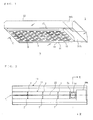
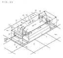
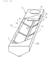
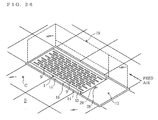
- FIG. 1 is a perspective view of a heating and cooling unit 1 of the present invention viewed from the bottom face side thereof
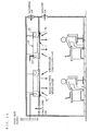
- FIG. 2 is a plan view of the heating and cooling unit 1 of the present invention.
- the heating and cooling unit 1 of the present invention comprises: a hood (box member) 13; an adjustment case 11 for receiving air-conditioned air from the air conditioning apparatus and adjusting the flow of the air-conditioned air; and a mixer case 16 for mixing air-conditioned air delivered from the adjustment case 11 with circulated air from the room inside and delivering the air to the room inside.
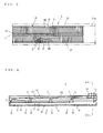
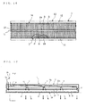
- FIG. 3 is a plan view of the heating and cooling unit 1 of the present invention wherein a part of an upper face of the mixer case 16 thereof is cut away
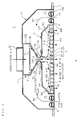
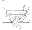
- FIG. 4 is a sectional side view of the adjustment case 11 and the mixer case 16 of the heating and cooling unit 1 of the present invention
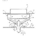
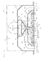
- FIG. 5 is an overall sectional view viewed from the E direction of FIG. 2
- FIG. 7 is a sectional view of a main part of the adjustment case 11 and the mixer case 16 viewed from the F direction of FIG. 4 .
- the hood 13 of the heating and cooling unit 1 of the present invention is buried in a ceiling C at room inside S, and the adjustment case 11 and the mixer case 16 are held inside the hood 13.
- the hood 13 is a flat rectangular parallelepiped box member having a lower opening part 14 at one face thereof.
- the hood 13 is buried in the ceiling C in a manner such that the one face having the lower opening part 14 faces the room inside S so as to form a flat face with the ceiling C, and a rectangular inspection port 19A is provided at one end part of the other face opposed to the one face.
- the inspection port 19A penetrates the hood 13 from the inside thereof to the outside thereof, and a cover is provided so as to be openable and closable.
- a rectangular inspection panel 17A is attached to the one face of the hood 13 at a position opposed to the inspection port 19A so as to be detachable.
- the inspection panel 17A is attached at a position close to one end side of the hood 13 in the vicinity of the inspection port 19A so as to form a flat face with the ceiling C.
- the hood 13 of the heating and cooling unit 1 of the present invention having such a structure can be easily installed even in a narrow ceiling.
- the adjustment case 11 is attached to the other face of the hood 13, the mixer case 16 is located below the adjustment case 11 so as to be opposed to the adjustment case 11, and the adjustment case 11 and the mixer case 16 are surrounded by a side wall of the hood 13.
- the adjustment case 11 comprises: an air inlet 18 for receiving air-conditioned air from the air conditioning apparatus; a holder case part 11B for holding air-conditioned air from the air inlet 18 and adjusting the flow, such as the wind direction, the wind velocity or the air volume, of air-conditioned air; and an air blowoff port 12A for blowing adjusted air, the flow of which is adjusted at the holder case part 11B, outward from the adjustment case 11.
- the air blowoff port 12A has a rectangular shape and is formed at the lower side of the holder case part 11B, and the adjustment case 11 is constructed to narrow toward the air blowoff port 12A.
- the air inlet 18 has a cylindrical shape and is provided to penetrate the other face of the hood 13 from the inside thereof to the outside thereof in the vicinity of the inspection port 19A of the hood 13.
- the holder case part 11B is connected with an edge at the lower side of the air inlet 18, has a taper shape narrowing downward, and is a box member extended along the longitudinal direction of the hood 13.
- a plurality of small wall strip parts 7, 7, ... 7 for guiding air-conditioned air from the air inlet 18 to the air blowoff port 12A and an inclined plate (suppression structure) 11a for suppressing unevenness of the air volume and the wind velocity of adjusted air to be blown from the air blowoff port 12A are provided inside the holder case part 11B.
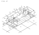
- FIG. 8 is a perspective view of the heating and cooling unit 1 of the present invention wherein a part of an upper face of the adjustment case 11 thereof is cut away.
- the holder case part 11B comprises two opposed inclined walls 7B, 7B, which are inclined in a symmetric fashion, and the small wall strip parts 7, 7, ... 7 are provided to protrude from the inside of the respective inclined walls 7B, 7B.
- the small wall strip parts 7, 7, ... 7 have a rectangular shape and are juxtaposed at an interval at the inclined walls 7B, 7B in a manner such that the longitudinal direction thereof is oriented to the vertical direction.
- the dimension (height) of the small wall strip parts 7, 7, ... 7 in the protrusion direction and the dimension (width) thereof in a direction crossing the protrusion direction can be freely changed, though it is preferable to set a vertical cross section of the small wall strip parts 7, 7, ... 7 to be 10 - 30 % of the maximum cross section in the direction of the shorter side of the adjustment case 11. This is because the wind direction cannot be adjusted when the height of the small wall strip parts 7, 7, ... 7 is too low, while air-conditioned air from the air inlet 18 cannot reach the leeward part of the small wall strip parts 7, 7, ... 7 as indicated by the bold dot-line arrows of FIG.
- a rectifier structure G composed of the inner face of the inclined walls 7B, 7B and the small wall strip parts 7, 7, ... 7 is provided at the adjustment case 11. Air-conditioned air which enters the unit from the air inlet 18 is guided by the rectifier structure G, or more specifically, the wind direction thereof is changed to vertically downward by resistance of the inner face of the inclined walls 7B, 7B and the small wall strip parts 7, 7, ... 7, so that the air-conditioned air flows toward the air blowoff port 12A.
- the inclined plate 11a has a rectangular plate shape which is extended along the longitudinal direction of the holder case part 11B.
- the inclined plate 11a is located to be opposed to the air blowoff port 12A in a manner such that the distance from the air blowoff port 12A gradually changes along the longitudinal direction. More specifically, the inclined plate 11a is attached to be inclined downward, that is, in a manner such that the distance from the air blowoff port 12A is the largest in the vicinity of the air inlet 18 and gradually decreases with increase in the distance from the air inlet 18.
- a partition plate 7a for guiding air-conditioned air from the air inlet 18 in the longitudinal direction of the adjustment case 11 is provided directly below the air inlet 18.
- the partition plate 7a is located to be opposed to the air inlet 18, and a clearance M is provided between the partition plate 7a and the inclined walls 7B, 7B. Accordingly, most of air-conditioned air from the air conditioning apparatus enters the unit from the air inlet 18 collides with the partition plate 7a, the wind direction thereof is changed to the longitudinal direction of the adjustment case 11, and only a part flows through the clearance M toward the air blowoff port 12A.
- the present invention is not limited to the example explained in Embodiment 1 of the present invention wherein the adjustment case 11 has a funnel-shaped cross section (or taper shape) narrowing toward the air blowoff port 12A having a wide upper part and a thinned lower part as described above.
- the mixer case 16 has a flat box shape, is attached in the hood 13 so as to be detachable and comprises: a mounting part 16B where a heat storage radiation flow divider (heat storage radiation member) 2, which will be described later, is attached; and a cover part 16A for covering the mounting part 16B.
- the cover part 16A and the mounting part 16B are formed in an integrated manner.
- the mounting part 16B is a flat rectangular parallelepiped box member having an opening at one face thereof at the upper side.
- the heat storage radiation flow divider 2 for obtaining low heat or high heat from mixed air and radiating heat toward the room inside is attached to the inner side of the other face (aperture face) 163 at the lower side opposed to the one face of the mounting part 16B so as to be thermally conducted with the mounting part 16B.
- heat stored in the heat storage radiation flow divider 2 is transferred to the mounting part 16B and the cover part 16A, and radiation heat (low heat or high heat) can reach a long-distance point with high efficiency by carrying out radiation cooling or radiation heating to the room inside S not only by the heat storage radiation flow divider 2 but also by the mounting part 16B and the cover part 16A.
- a plurality of apertures 9, 9, ... 9 for blowing the mixed air to the outside (room inside S) are provided at the other face 163 of the mounting part 16B.
- the apertures 9, 9, ... 9 are long holes which penetrate the mixer case 16 (mounting part 16B) from the inside thereof to the outside thereof.
- Mixed air in the mixer case 16 passes the heat storage radiation flow divider 2 and the apertures 9, 9, ... 9, and is supplied to the room inside.
- the present invention is not limited to the example explained in Embodiment 1 of the present invention wherein the apertures 9, 9, ... 9 are long holes, and the apertures 9, 9, ... 9 may have a shape such as a round shape or a rectangular shape.
- the arrangement, the number or the like of the apertures 9, 9, ... 9 may be changed as occasion rises.
- the total area ratio of the whole area of the apertures 9, 9, ... 9 to the whole area of the other face 163 of the mixer case 16 (mounting part 16B) is preferable to set the total area ratio of the whole area of the apertures 9, 9, ... 9 to the whole area of the other face 163 of the mixer case 16 (mounting part 16B) equal to or larger than 30 % in order to maximize the radiation heating action of the heat storage radiation flow divider 2 and the mixer case 16 to the room inside S and the heat transfer action by mixed air emission from the mixer case 16, though the present invention is not limited to this.
- the heat storage radiation flow divider 2 comprises: a plurality of heat transfer plate(flow dividing fin)s 8, 8, ... 8; and a plurality of elliptical heat storage pipes 99, 99, ... 99 for storing low heat or high heat transferred from the heat transfer plates 8, 8, ... 8.
- the heat transfer plates 8, 8, ... 8 have a rectangular shape, obtain low heat or high heat from the mixed air, and transfer heat to the mounting part 16B, the cover part 16A and the elliptical heat storage pipes 99, 99, ... 99.
- the elliptical heat storage pipes 99, 99, ... 99 have an elliptical longitudinal section, and are attached in a manner such that the major axis direction of the ellipse is oriented to the vertical direction. Accordingly, mixed air in the mixer case 16 can pass the heat storage radiation flow divider 2 smoothly with a low pressure loss.
- the heat transfer plates 8, 8, ... 8 are made of, for example, aluminum, copper, mica, titanium, Carbolite or the like having high thermal conductivity and high thermal emissivity, and are juxtaposed to be opposed to each other at a proper interval in the direction of the shorter side of the mounting part 16B.
- the elliptical heat storage pipes 99, 99, ... 99 are installed so as to penetrate the heat transfer plates 8, 8, ... 8 in the juxtaposition direction of the heat transfer plates 8, 8, ... 8. It is to be noted that the elliptical heat storage pipes 99, 99, ...
- the heat storage radiation flow divider 2 has a flat rectangular parallelepiped shape as a whole, similar to the inner shape of the mounting part 16B.
- the wind velocity of mixed air in the mixer case 16 to pass the heat storage radiation flow divider 2 is decreased by the heat transfer plates 8, 8, ... 8, the flow of the mixed air is divided into a plurality of layers and the mixed air is supplied to the room inside S in a so-called multi-layer flow manner, and therefore it is possible to suppress the draft to be given to the user of the room inside S.
- the present invention is not limited to the example explained in the present embodiment wherein a plurality of elliptical heat storage pipes 99, 99, ... 99 are provided, and one long elliptical heat storage pipe 99 may be folded to have a meandering shape. Moreover, the elliptical heat storage pipes 99, 99, ... 99 may have not an elliptical cross section but a circular cross section.
- FIG. 6 is a sectional view for illustrating a main part of a variation of a heat storage radiation flow divider 2 of Embodiment 1 of the present invention.
- a heat storage member T for obtaining heat of the mixed air via the elliptical heat storage pipes 99, 99, ... 99 and storing the heat is filled in the elliptical heat storage pipes 99, 99, ... 99.
- the heat storage member T needs only to be made of material which can store heat and release heat for a long period of time, and may be in a liquid state or a solid state.
- the shape, the number, the pitch and the like of the heat transfer plates 8, 8, ... 8 and the apertures 9, 9, ... 9 are set in a manner such that the velocity of mixed air before passing the heat storage radiation flow divider 2 is decreased to be equal to or lower than half of the velocity of mixed air after passing the heat storage radiation flow divider 2, or more preferably equal to or lower than 20 % to 30 %, in order to ensure an optimum function of flow division, diffusion, heat transfer action and the like of mixed air to the room inside S.
- the cover part 16A is provided to cover the one face of the mounting part 16B at the upper side.
- the cover part 16A has a shape to be obtained by folding an outer edge of an upper plate 161, which is made of a rectangular plate material having a size substantially equal to the heat storage radiation flow divider 2, downward and extending the same. Accordingly, a space surrounded by the inner face of the cover part 16A and the heat storage radiation flow divider 2 is formed in the mixer case 16. In the space, adjusted air from the adjustment case 11 and circulated air from the circulated air path 15 are mixed by a method, which will be described later, and become mixed air.
- an induction port (air suction port) 162 for suctioning adjusted air from the adjustment case 11 and inducing and suctioning circulated air from the circulated air path 15 is provided at a central part (denoted by L in FIG. 3 ) in the direction of the shorter side of the upper plate 161.
- the induction port 162 has a rectangular shape elongated in the longitudinal direction of the upper plate 161 and is formed to be opposed to the air blowoff port 12A of the adjustment case 11. It is to be noted that the induction port 162 is formed at the midpoint between two opposed side faces of the upper plate 161 in the lateral direction and constructed to be matched with the air blowoff port 12A. It is to be noted that the circulated air path 15 is formed outside the two side faces and the upper plate 161.
- the heating and cooling unit 1 is provided with the guide path K guiding the adjusted air blown out from the air blowoff port 12A of the adjustment case 11 to the mixer case 16.
- the guide path K includes a part of the air blowoff guide 12 (or the air blowoff port air volume adjustment member 3), and a part of the induction guide 10 (or the induction port air volume adjustment member 5).
- the guide path K is constructed by the guide flange 32 of the air blowoff guide 12 (or the air blowoff port air volume adjustment member 3), the space N, and the guide flange 51 of the induction guide 10 (or the induction port air volume adjustment member 5), and the adjusted air blown out from the air blowoff port 12A is guided by the guide path K, and flows into the induction port 162.
- the circulated air from the room inside S is suctioned into the induction port 162 through the guide path K from the space N via the circulated air path 15.
- the air blowoff guide 12 is attached to a lower end part of the inclined walls 7B, 7B of the adjustment case 11 in the vicinity of the air blowoff port 12A, and guides the wind direction of adjusted air blown from the air blowoff port 12A to flow into the induction port 162. Moreover, the air blowoff guide 12 comprises an air volume adjustment structure A for adjusting the air volume of the adjusted air.
- the air volume adjustment structure A is composed of: a pair of air blowoff port air volume adjustment members 3, 3 attached to the outer side of a lower end part of the inclined walls 7B, 7B so as to be slidable; and screw members 4, 4 for fixing the air blowoff port air volume adjustment members 3, 3 so as to be slidable.
- the air blowoff port air volume adjustment members 3, 3 are made of rectangular plate materials having a longitudinal dimension substantially equal to the longitudinal dimension of the air blowoff port 12A.
- An upper end part of each of the air blowoff port air volume adjustment members 3, 3 in the lateral direction is fixed at an edge part at each long side of the air blowoff port 12A by each of the screw members 4, 4 so as to be slidable, and a lower end part of each of the air blowoff port air volume adjustment members 3, 3 is folded and extended toward the induction port 162 to form each of guide flanges 32, 32.
- a long through hole is provided at an upper end part of each of the air blowoff port air volume adjustment members 3, 3, and each air blowoff port air volume adjustment member 3 is fixed by a screw member 4, such as a screw or a rivet, having a diameter equal to the minor axis of the long through hole so as to be slidable in the major axis direction of the long through hole.
- the air volume of adjusted air to be blown from the air blowoff port 12A can be adjusted when the pair of air blowoff port air volume adjustment members 3, 3 slide respectively along the outer face of the inclined walls 7B, 7B in the incline direction thereof so as to open or close the air blowoff port 12A, that is, when the interval (HA) between the air blowoff port air volume adjustment members 3, 3 increases or decreases.
- adjusted air to be blown from the air blowoff port 12A exits the air blowoff port 12A and then the wind direction thereof is guided by the guide flanges 32, 32. That is to say, the air blowoff guide 12 functions to adjust the air volume of the adjusted air and to guide the adjusted air.
- the induction guide 10 is attached to a central part of the upper plate 161 in the vicinity of the induction port 162 and guides adjusted air to be blown from the air blowoff port 12A so as to be suctioned into the induction port 162 and guides circulated air from the circulated air path 15 so as to be induced and suctioned.
- the induction guide 10 is located to be opposed to the air blowoff guide 12 across the space N as described above.
- the induction guide 10 comprises an air volume adjustment structure B for adjusting the volume of air to be suctioned.
- the air volume adjustment structure B is composed of: a pair of induction port air volume adjustment members 5, 5 attached to the outer side of the upper plate 161 so as to be slidable; and screw members 6, 6 for fixing the induction port air volume adjustment members 5, 5 so as to be slidable.
- the induction port air volume adjustment members 5, 5 are made of rectangular plate materials having a longitudinal dimension substantially equal to the longitudinal dimension of the induction port 162. An outer end part of the central part at the outer side in the direction of the shorter side of each of the induction port air volume adjustment members 5, 5 is fixed at an edge part at each long side of the induction port 162 by each of the screw members 6, 6 so as to be slidable. Moreover, an inner end part of each of the induction port air volume adjustment members 5, 5 is folded and extended toward the inner side of the mixer case 16 so as to form each of the guide flanges 51, 51.
- a long through hole is provided at an outer end part of each of the induction port air volume adjustment members 5, 5, and each induction port air volume adjustment member 5 is fixed by a screw member 6, such as a screw or a rivet, having a diameter equal to the minor axis of the long through hole so as to be slidable in the major axis direction of the long through hole.
- the volume of air to be suctioned into the induction port 162 can be adjusted when the pair of induction port air volume adjustment members 5, 5 slide respectively along the outer face of the upper plate 161 so as to open or close the induction port 162, that is, when the interval (HB) between the induction port air volume adjustment members 5, 5 increases or decreases.
- the wind direction of air, which passes the induction port 162 is guided by the guide flanges 51, 51.
- the present invention is not limited to the example explained in Embodiment 1 of the present invention wherein the lower end part of the air blowoff port air volume adjustment members 3 and the inner end part of the induction port air volume adjustment members 5 are folded. It is to be noted that any one of the air blowoff guide 12 and the induction guide 10 may be omitted.
- the following description will explain a method of inducing and suctioning circulated air in the circulated air path 15 into the mixer case 16 and mixing the circulated air with adjusted air from the adjustment case 11 so as to make mixed air.
- Embodiment 1 When adjusted air blown from the air blowoff port 12A (air blowoff guide 12) is suctioned into the induction port 162 (induction guide 10), the air pressure around the air flow from the air blowoff port 12A to the induction port 162 lowers.
- the air blowoff guide 12 (air blowoff port 12A) and the induction guide 10 (induction port 162) in Embodiment 1 are located in opposed positions across the space N, through which air in the vicinity (circulated air in the circulated air path 15) flows into the induction guide 10 (the induction port 162). Accordingly, when the air pressure around the air flow lowers, circulated air in the circulated air path 15 is caught up in the air flow (as indicated by the dot-line arrows W1 in FIG.
- Circulated air induced in such a manner is suctioned into the mixer case 16 together with adjusted air and is mixed with the adjusted air, the flow of the air is divided, (as indicated by the dot-line arrows W2 in FIG. 5 ) and the air is supplied to the room inside S.
- the air pressure in the circulated air path 15 lowers by the volume of circulated air suctioned into the mixer case 16 at this time, and circulated air is supplied from the room inside (as indicated by the dot-line arrows W3 in FIG. 5 ) since the circulated air path 15 is communicatively connected with the room inside (circulated air) as described above.
- Air-conditioned air is set, for example, to have a temperature higher than the dew-point temperature of the room inside S and a low absolute humidity when mixed with circulated air in order to prevent dew condensation and enhance the air conditioning efficiency, though the present invention is not limited to this.
- the guide path K is not limited to such a structure.
- the feed path K may be constructed without providing the air blowoff guide 12 and the induction guide 10.
- the feed path K may be constructed by connecting the air blowoff port 12A with the induction port 162 by a guide path member such as bellows and providing a hole at the guide path member so as to be communicated with circulated air in the circulated air path 15.
- FIG. 9 is a sectional view of a main part of a heating and cooling unit 1 of Embodiment 2 of the present invention.
- a lighting system R for lighting room inside S is provided at an edge part of a lower opening part 14 of a hood 13.
- the size of the other face 163 of a mounting part 16B is smaller than the size of the lower opening part 14 of the hood 13, and a clearance (passage clearance) 141 is formed between the lower opening part 14 of the hood 13 and the other face 163 of the mounting part 16B when the heating and cooling unit 1 is installed. Circulated air from the room inside S passes the clearance 141 and is suctioned into a circulated air path 15.
- the lighting system R is provided at the clearance 141 in a proper manner.
- the lighting system R is provided so as not to obstruct circulated air passing the clearance 141, so that circulated air can pass freely. That is to say, the lighting system R is exposed to circulated air passing the clearance 141. Accordingly, circulated air passing the clearance 141 comes into contact with the lighting system R and obtains heat generated by the lighting system R. The obtained heat is used for reheating or preheating in mixing of the air-conditioned air and circulated air.
- heat from the lighting system R is used for reheating of air-conditioned air and therefore it is possible to prevent dew condensation reliably and to further decrease the air supply volume of air-conditioned air so as to further reduce the cost.
- heat from the lighting system R is used for preheating of air-conditioned air and therefore it is possible to decrease the capacity of a device for feeding the air-conditioned air and to enhance the heating capacity.
- the lighting system R is, for example, a fluorescent tube, an incandescent lamp or an LED, and the number, the position thereof or the like can be changed in a proper manner.
- FIG. 10 is a sectional view of a main part of a heat storage radiation flow divider 2 of Embodiment 3 of the present invention wherein a part thereof is omitted
- FIG. 11 is a sectional view of a main part of a mixer case 16 and a heat storage radiation flow divider 2 of Embodiment 3 viewed from the J direction of FIG. 10 .
- a heating and cooling unit 1 of Embodiment 3 comprises short tubular protrusions 98, 98, 98, ... 98 formed to protrude from one face of each heat transfer plate 8.
- the protrusions 98, 98, 98, ... 98 are juxtaposed at one face of each heat transfer plate 8 at a proper interval along the longitudinal direction of the heat transfer plate 8. More particularly, apertures 9 are juxtaposed below the respective protrusions 98 at a predetermined interval as illustrated in FIG. 10 .
- the protrusions 98 have an elliptical cross section and are provided in a manner such that the major axis direction of the ellipse is oriented to the vertical direction.
- the protrusions 98, 98, 98, ... 98 are further juxtaposed in the juxtaposition direction of the heat transfer plates 8, 8, 8, ... 8 with each central axis thereof being positioned on the same line.
- the protrusions 98 have heat storage capability, and obtain heat from mixed air via the heat transfer plates 8, store the heat and radiate the heat toward the room inside S.
- a protrusion 98 of one heat transfer plate 8 is extended to come into contact with another adjacent heat transfer plate 8 and supports the adjacent heat transfer plate 8 so as to prevent warping of the adjacent heat transfer plate 8.
- Radiation heating to the room inside S by the heat storage radiation flow divider 2 is directed downward via the apertures 9, 9, 9, ... 9.
- radiation heating is directed obliquely downward from the apertures 9 in the vicinity of a local area below the protrusions 98. That is, radiation heating in the vicinity of the protrusions 98 widely moves directly downward and obliquely downward from the apertures 9 since heat moves downward along the peripheral face of the protrusions 98. Accordingly, it is possible to uniform the temperature distribution at the room inside S.
- the flow of mixed air to pass the apertures 9, 9, 9, ... 9 is further divided not only by the heat transfer plates 8, 8, ... 8 but also by the protrusions 98, 98, 98, ... 98, the wind velocity of the mixed air is further lowered and the mixed air is supplied to the room inside S in a further fine multi-layer flow manner and therefore it is possible to suppress the draft to be given to the user of the room inside S.
- the present invention is not limited to the example explained in Embodiment 3 wherein the protrusion 98 of one heat transfer plate 8 is extended to come into contact with another adjacent heat transfer plate 8, and a protrusion 98 of one heat transfer plate 8 may be extended in a proper manner to the vicinity of another adjacent heat transfer plate 8.
- the protrusion 98 may be formed to be integrated with a heat transfer plate 8, or may be constructed so as to be detachable.
- the present invention is not limited to the example explained in Embodiment 3 wherein the protrusions 98 have an elliptical shape, and the protrusions 98 may have a circular shape or a polygonal shape.
- heating and cooling apparatus is a so-called induction emission air conditioning apparatus as an example, with reference to the drawings.
- FIG. 12 is a perspective view illustrating the case of installing an induction emission air conditioning apparatus according to Embodiment 4 of the present invention in a ceiling wherein a part of an upper face thereof is cut away, and viewed from the above
- FIG. 13 is a perspective view of the induction emission air conditioning apparatus according to Embodiment 4 of the present invention viewed from a room inside side thereof
- FIG. 14 is a brief explanatory view illustrating an example of usage of the induction emission air conditioning apparatus according to Embodiment 4 of the present invention.
- the induction emission air conditioning apparatus is provided with the casing 19 buried in the ceiling C at the room inside S, and the inner side of the casing 19 is provided with the heat exchanger 20 through which the feed air induced from the outdoor side passes, and the fan 22 passing the feed air through the heat exchanger 20. Further, the inner side of the casing 19 is provided with the heating and cooling unit 1 for blowing the mixed air obtained by inducing and suctioning the air in the room inside S by the feed air passing through the heat exchanger 20 and mixing with the feed air to the room inside S in a laminar manner, and emitting the heat of the mixed air to the room inside S, and the lighting system R for lighting the room inside S.
- the inner side of the casing 19 is provided with the air blowing path 24 communicating and coupling the heat exchanger 20, the fan 22 and the heating and cooling unit 1, the detector 28 such as a human sensing sensor or the like detecting existence, a position or the like of a human body in the room inside S so as to output a signal according to a detection result, and a controller 29 for controlling one or both of the air conditioning performance (increase / decrease or on and off of the air volume, the air blowoff temperature or the like) and the light modulation of the lighting system (increase / decrease or on and off of the illumination intensity) in response to the signal from the detector 28. It is to be noted that they are integrated. Since the induction emission air conditioning apparatus according to the present invention has the structure mentioned above, it can be easily installed even in a narrow back side of a ceiling.
- the space in the back side of the ceiling C serves as a so-called ceiling chamber.
- the air in the back side (the ceiling chamber) of the ceiling C is passed through the heat exchanger 20 as the feed air.
- the feed air includes the processed external air in which temperature and humidity is controlled by an outside adjusting apparatus (not illustrated) or the like, the raw external air in which temperature and humidity is not controlled, the mixed air of the processed external air and the circulate air from the room inside S, the mixed air of the raw external air and the circulated air, the circulated air, or the like.
- the heat exchanger 20 is provided with the heat transfer pipe, and the heat transfer pipe is an elliptical pipe.
- the heat exchanger 20 it is possible to utilize various systems such as a hot / cold water coil heat exchanging the air to be fed by the cold water or the hot water, a direct expanding coil heat exchanging the air to be fed by the refrigerant of the water heat source or the air heat source heat pump, and the like, and it is not limited to an illustrated example.
- reference numeral 31 denotes a drain pan.
- the casing 19 is a flat rectangular parallelepiped shape which is formed into a rectangular shape in a plan view, and is provided with the induction port 30 in one side face for suctioning the feed air.
- the heat exchanger 20 is arranged in one, and the fan 22 carrying out the air blowing is arranged in the other, in both ends of the heating and cooling unit 1 which is formed into a rectangular shape in a bottom view.
- the heating and cooling unit 1 within the casing 19 is formed into a flat rectangular parallelepiped shape in which a dimension in a short direction is slightly shorter than the casing 19, and is provided in such a manner that its longitudinal direction coincides with a longitudinal direction of the casing 19. It is to be noted that the lighting system R is provided in both end sides in the longitudinal direction of the heating and cooling unit 1. In other words, the lighting system R is arranged in a lower side of each of the heat exchanger 20 and the fan 22.
- the air blowing path 24 is formed in the upper side of the heating and cooling unit 1.
- the air blowing path 24 has a windward side wind path 25 communicating and coupling the heat exchanger 20 and the fan 22, and a leeward side wind path 26 communicating and coupling the fan 22 and the heating and cooling unit 1.
- the windward side wind path 25 and the leeward side wind path 26 are juxtaposed, and are structured in such a manner that the wind directions are reversed to each other.
- the feed air from the leeward side wind path 26 flows into the heating and cooling unit 1 via the air inlet 18.
- the air inlet 18 is formed in the upper face of the heating and cooling unit 1 in the vicinity of the heat exchanger 20 which is spaced from the fan 22. In other words, it is structured such that the air blowing distance of the feed air from the induction port 30 to the air inlet 18 becomes longer.
- the air blowing path 24 constructed by the windward side wind path 25 and the leeward side wind path 26 is constructed by comparting by the partition plate 21 with communication port and the duct member 23, however, the structure may be freely changed.
- the feed air flows based on the drive of the fan 22, according to the order of induction port 30 ⁇ heat exchanger 20 ⁇ windward side wind path 25 ⁇ fan 22 ⁇ leeward side wind path 26 ⁇ air inlet 18 ⁇ heating and cooling unit 1.
- induction port 30 heat exchanger 20 ⁇ windward side wind path 25 ⁇ fan 22 ⁇ leeward side wind path 26 ⁇ air inlet 18 ⁇ heating and cooling unit 1.
- these structures can be freely changed, and although an illustration is omitted, the structure may be made, for example such that the feed air is induced from the fan 22 side by changing the communication position between the windward side wind path 25 and the leeward side wind path 26 and the position of the induction port 30, and flows according to the order of fan 22 ⁇ heat exchanger 20 ⁇ heating and cooling unit 1.
- FIG. 15 is a plan view of the heating and cooling unit 1 of the induction emission air conditioning apparatus according to Embodiment 4 of the present invention.
- the heating and cooling unit 1 is provided with a hood 13, an adjustment case 11 for receiving the feed air and adjusting the flow of the feed air, and a mixer case 16 for mixing the adjusted air delivered from the adjustment case 11 with the circulated air from the room inside so as to feed to the room inside.
- FIG. 16 is a plan view of the heating and cooling unit 1 in the induction emission air conditioning apparatus according to Embodiment 4 of the present invention wherein a part of an upper face of the mixer case 16 of the heating and cooling unit 1 is cut away
- FIG. 17 is a sectional side view of the adjustment case 11 and the mixer case 16 of the heating and cooling unit 1 in the induction emission air conditioning apparatus according to Embodiment 4 of the present invention
- FIG. 18 is a sectional view of a whole viewed from the E direction of FIG. 15
- FIG. 19 is a sectional view for illustrating a main part of the adjustment case 11 and the mixer case 16 viewed from the F direction of FIG. 17 .
- the hood 13 of the heating and cooling unit 1 according to the present invention is provided in the casing 19, and the adjustment case 11 and the mixer case 16 are housed inside the hood 13.
- the hood 13 is a flat rectangular parallelepiped box member having a lower opening part 14 in one face.
- the hood 13 is provided in such a manner that the one face having the lower opening part 14 is directed to the room inside S while being flush with the ceiling C.
- the adjustment case 11 is attached to the other face which is opposed to the one face of the hood 13, the mixer case 16 is arranged below the adjustment case 11 so as to be opposed to the adjustment case 11, and they are surrounded by the side wall of the hood 13.
- a circulated air path 15 communicatively connecting the circulated air in the room inside S from the lower opening part 14 to the guide path K mentioned above is formed between the adjustment case 11 and the mixer case 16, and the inner side of the hood 13.
- the circulated air path 15 is communicatively connected with the room inside (the circulated air), and is structured such that the circulated air can always come in and out the circulated air path 15, and the circulated air is suctioned into the guide path K via the circulated air path 15.
- the adjustment case 11 is provided with an air inlet 18 which is continuously provided in the air blowing path 24 so as to receive the feed air, a holder case part 11B which holds the feed air from the air inlet 18, and adjusts the flow such as the wind direction, the wind velocity, the air volume of the feed air, and a air blowoff port 12A which blows off the adjusted air having the flow adjusted by the holder case part 11B toward the outer side of the adjustment case 11.
- the air blowoff port 12A is formed into a rectangular shape, and is formed in a lower side of the holder case part 118, and the adjustment case 11 is structured such as to be narrowed toward the air blowoff port 12A.
- the holder case part 11B is a box member which has a taper shape which narrows toward a lower side, and extends along a longitudinal direction of the hood 13.
- the inner side of the holder case part 11B is provided with a plurality of small wall strip parts 7, 7, ... 7 for guiding the feed air from the air inlet 18 to the air blowoff port 12A, and a inclined plate 11a for suppressing unevenness of the air volume and the wind velocity of the adjusted air blown out from the air blowoff port 12A.
- FIG. 20 is a perspective view of a heating and cooling unit in the induction emission air conditioning apparatus according to Embodiment 4 of the present invention wherein a part of an upper face of an adjustment case of a heating and cooling unit.
- the holder case part 11B is provided with two opposed inclined walls 7B and 7B which are inclined symmetrically, and the small wall strip parts 7, 7, ... 7 are provided to protrude from the inside of the respective inclined walls 7B and 7B.
- the small wall strip parts 7, 7, ... 7 have the rectangular shape, and are juxtaposed at an interval at the inclined walls 7B and 7B in a manner such that the longitudinal direction thereof is oriented to the vertical direction.
- the dimension (height) of the small wall strip parts 7, 7, ... 7 in the protrusion direction and the dimension (width) thereof in a direction crossing the protrusion direction can be freely changed, though it is preferable to set the vertical cross section of the small wall strip parts 7, 7, ... 7 to be 10 - 30 % of the maximum cross section in the direction of the shorter side of the adjustment case 11. This is because the wind direction cannot be adjusted when the height of the small wall strip parts 7, 7, ... 7 is too low, while feed air from the air inlet 18 cannot reach the leeward part of the small wall strip parts 7, 7, ... 7 as indicated by the bold dot-line arrows of FIG.
- Embodiment 4 of the present invention a rectifier structure G composed of the inner face of the inclined walls 7B, 7B and the small wall strip parts 7, 7, ... 7 is provided at the adjustment case 11.
- the feed air entering from the air inlet 18 is guided by the rectifier structure G or more specifically, the wind direction thereof is changed to vertically downward by resistance of the inner face of the inclined walls 7B, 7B and the small wall strip parts 7, 7, ... 7, so that the feed air flows toward the air blowoff port 12A.
- the inclined plate 11a has a rectangular plate shape which is extended along the longitudinal direction of the holder case part 11B.
- the inclined plate 11a is located to be opposed to the air blowoff port 12A in a manner such that the distance from the air blowoff port 12A gradually changes along the longitudinal direction. More specifically, the inclined plate 11a is attached to be inclined downward, that is, in a manner such that the distance from the air blowoff port 12A is the largest in the vicinity of the air inlet 18 and gradually decreases with increase in the distance from the air inlet 18.
- a partition plate 7a for guiding feed air from the air inlet 18 in the longitudinal direction of the adjustment case 11 is provided directly below the air inlet 18.
- the partition plate 7a is located to be opposed to the air inlet 18, and a clearance M is provided between the partition plate 7a and the inclined walls 7B, 7B. Accordingly, most of feed air entering from the air inlet 18 collides with the partition plate 7a, the wind direction thereof is changed to the longitudinal direction of the adjustment case 11, and only a part flows through the clearance M toward the air blowoff port 12A.
- the present invention is not limited to the example explained in Embodiment 4 of the present invention wherein the adjustment case 11 has a funnel-shaped cross section (or taper shape) narrowing toward the air blowoff port 12A having a wide upper part and a thinned lower part as described above.
- the mixer case 16 is the same as the mixer case 16 according to Embodiment 1 illustrated in FIG. 6 . More particularly, the mixer case 16 according to Embodiment 4 is formed into the flat box shape, is detachably mounted in the hood 13, and is provided with an mounting part 16B to which the heat storage radiation flow divider 2 mentioned above is attached, and a cover part 16A for covering the mounting part 16B, and the cover part 16A and the mounting part 16B are formed in an integrated manner (hereinafter, see FIG. 6 ).
- the mounting part 16B is a flat rectangular parallelepiped box member in which one upper face is open.
- the heat storage radiation flow divider 2 for obtaining low heat or high heat from the mixed air so as to radiate heat toward the room inside is provided in the inner side of the other face 163 at the lower side opposed to the one face of the mounting part 16B so as to be thermally conducted with the mounting part 16B (and cover part 16A). Accordingly, heat stored in the heat storage radiation flow divider 2 is transferred to the mounting part 16B and the cover part 16A, and radiation heat (low heat or high heat) can reach a long-distance point with high efficiency by carrying out radiation cooling or radiation heating to the room inside S not only by the heat storage radiation flow divider 2 but also by the mounting part 16B and the cover part 16A.
- a plurality of apertures 9, 9, ... 9 for blowing the mixed air to the outside (room inside S) are provided at the other face 163 of the mounting part 16B.
- the apertures 9, 9, ... 9 are long holes which penetrate the mixer case 16 (mounting part 16B) from the inside thereof to the outside thereof.
- Mixed air in the mixer case 16 passes the heat storage radiation flow divider 2 and the apertures 9, 9, ... 9, and is supplied to the room inside.
- the present invention is not limited to the example explained in Embodiment 4 of the present invention wherein the apertures 9, 9, ... 9 are long holes, and the apertures 9, 9, ... 9 may have a shape such as a round shape or a rectangular shape.
- the arrangement, the number or the like of the apertures 9, 9, ... 9 may be changed as occasion rises.
- the total area ratio of the whole area of the apertures 9, 9, ... 9 to the whole area of the other face 163 of the mixer case 16 (mounting part 16B) is preferable to set the total area ratio of the whole area of the apertures 9, 9, ... 9 to the whole area of the other face 163 of the mixer case 16 (mounting part 16B) equal to or larger than 30 % in order to maximize the radiation heating action of the heat storage radiation flow divider 2 and the mixer case 16 to the room inside S and the heat transfer action by mixed air emission from the mixer case 16, though the present invention is not limited to this.
- the heat storage radiation flow divider 2 comprises: a plurality of heat transfer plates 8, 8, ... 8; and a plurality of elliptical heat storage pipes 99, 99, ... 99 for storing low heat or high heat transferred from the heat transfer plates 8, 8, ... 8.
- the heat transfer plates 8, 8, ... 8 have a rectangular shape, obtain low heat or high heat from the mixed air, and transfer heat to the mounting part 16B, the cover part 16A and the elliptical heat storage pipes 99, 99, ... 99.
- the elliptical heat storage pipes 99, 99, ... 99 have an elliptical longitudinal section, and are attached in a manner such that the major axis direction of the ellipse is oriented to the vertical direction. Accordingly, mixed air in the mixer case 16 can pass the heat storage radiation flow divider 2 smoothly with a low pressure loss.
- the heat transfer plates 8, 8, ... 8 are made of, for example, aluminum, copper, mica, titanium, Carbolite or the like having high thermal conductivity and high thermal emissivity, and are juxtaposed to be opposed to each other at a proper interval in the direction of the shorter side of the mounting part 16B.
- the elliptical heat storage pipes 99, 99, ... 99 are installed so as to penetrate the heat transfer plates 8, 8, ... 8 in the juxtaposition direction of the heat transfer plates 8, 8, ... 8. It is to be noted that the elliptical heat storage pipes 99, 99, ...
- the heat storage radiation flow divider 2 has a flat rectangular parallelepiped shape as a whole, similar to the inner shape of the mounting part 16B.
- the wind velocity of mixed air in the mixer case 16 to pass the heat storage radiation flow divider 2 is decreased by the heat transfer plates 8, 8, ... 8, the flow of the mixed air is divided into a plurality of layers and the mixed air is supplied to the room inside S in a so-called laminar manner, and therefore it is possible to suppress the draft to be given to the user of the room inside S.
- the present invention is not limited to the example explained in the present embodiment wherein a plurality of elliptical heat storage pipes 99, 99, ... 99 are provided, and one long elliptical heat storage pipe 99 may be folded to have a meandering shape. Moreover, the elliptical heat storage pipes 99, 99, ... 99 may have not an elliptical cross section but a circular cross section.
- the structure of the elliptical heat storage pipes 99, 99, ... 99 is not limited to the above description.
- a heat storage member T for obtaining heat of the mixed air via the elliptical heat storage pipes 99, 99, ... 99 and storing the heat is filled in the elliptical heat storage pipes 99, 99, ... 99.
- the heat storage member T needs only to be made of material which can store heat and release heat for a long period of time, and may be in a liquid state or a solid state.
- the shape, the number, the pitch and the like of the heat transfer plates 8, 8, ... 8 and the apertures 9, 9, ... 9 are set in a manner such that the velocity of mixed air before passing the heat storage radiation flow divider 2 is decreased to be equal to or lower than half of the velocity of mixed air after passing the heat storage radiation flow divider 2, or more preferably equal to or lower than 20 % to 30 %, in order to ensure an optimum function of flow division, diffusion, heat transfer action and the like of mixed air to the room inside S.
- the cover part 16A is provided to cover the one face of the mounting part 16B at the upper side.
- the cover part 16A has a shape to be obtained by folding an outer edge of an upper plate 161, which is made of a rectangular plate material having a size substantially equal to the heat storage radiation flow divider 2, downward and extending the same. Accordingly, a space surrounded by the inner face of the cover part 16A and the heat storage radiation flow divider 2 is formed in the mixer case 16. In the space, adjusted air from the adjustment case 11 and circulated air from the circulated air path 15 are mixed by a method described above, and become mixed air (see the description of FIG. 5 ).
- an induction port (air suction port) 162 for suctioning adjusted air from the adjustment case 11 and inducing and suctioning circulated air from the circulated air path 15 is provided at a central part (denoted by L in FIG. 16 ) in the direction of the shorter side of the upper plate 161.
- the induction port 162 has a rectangular shape elongated in the longitudinal direction of the upper plate 161 and is formed to be opposed to the air blowoff port 12A of the adjustment case 11. It is to be noted that the induction port 162 is formed at the midpoint between two opposed side faces of the upper plate 161 in the lateral direction and constructed to be matched with the air blowoff port 12A. It is to be noted that the circulated air path 15 is formed outside the two side faces and the upper plate 161.
- the heating and cooling unit 1 is provided with the air blowoff guide 12 which is attached in the vicinity of the air blowoff port 12A of the adjustment case 11, and the induction guide 10 which is arranged so as to be opposed to the air blowoff guide 12 with the space N being sandwiched therebetween, and is attached in the vicinity of the induction port 162 of the mixer case 16.
- the air blowoff guide 12 is attached to a lower end part of the inclined walls '7B, '7B of the adjustment case 11 in the vicinity of the air blowoff port 12A, and guides the wind direction of adjusted air blown from the air blowoff port 12A to flow into the induction port 162. Moreover, the air blowoff guide 12 comprises an air volume adjustment structure A for adjusting the air volume of the adjusted air.
- the air volume adjustment structure A is composed of: a pair of air blowoff port air volume adjustment members 3, 3 attached to the outer side of a lower end part of the inclined walls 7B, 7B so as to be slidable; and screw members 4, 4 for fixing the air blowoff port air volume adjustment members 3, 3 so as to be slidable.
- the air blowoff port air volume adjustment members 3, 3 are made of rectangular plate materials having a longitudinal dimension substantially equal to the longitudinal dimension of the air blowoff port 12A.
- An upper end part of each of the air blowoff port air volume adjustment members 3, 3 in the lateral direction is fixed at an edge part at each long side of the air blowoff port 12A by each of the screw members 4, 4 so as to be slidable, and a lower end part of each of the air blowoff port air volume adjustment members 3, 3 is folded and extended toward the induction port 162 to form each of guide flanges 32, 32.
- a long through hole is provided at an upper end part of each of the air blowoff port air volume adjustment members 3, 3, and each air blowoff port air volume adjustment member 3 is fixed by a screw member 4, such as a screw or a rivet, having a diameter equal to the minor axis of the long through hole so as to be slidable in the major axis direction of the long through hole.
- the air volume of adjusted air to be blown from the air blowoff port 12A can be adjusted when the pair of air blowoff port air volume adjustment members 3, 3 slide respectively along the outer face of the inclined walls 7B, 7B in the incline direction thereof so as to open or close the air blowoff port 12A, that is, when the interval (HA) between the air blowoff port air volume adjustment members 3, 3 increases or decreases.
- adjusted air to be blown from the air blowoff port 12A exits the air blowoff port 12A and then the wind direction thereof is guided by the guide flanges 32, 32. That is to say, the air blowoff guide 12 functions to adjust the air volume of the adjusted air and to guide the adjusted air.
- the induction guide 10 is attached to a central part of the upper plate 161 in the vicinity of the induction port 162 and guides adjusted air to be blown from the air blowoff port 12A so as to be suctioned into the induction port 162 and guides circulated air from the circulated air path 15 so as to be induced and suctioned.
- the induction guide 10 is located to be opposed to the air blowoff guide 12 across the space N as described above.
- the induction guide 10 comprises an air volume adjustment structure B for adjusting the volume of air to be suctioned.
- the air volume adjustment structure B is composed of: a pair of induction port air volume adjustment members 5, 5 attached to the outer side of the upper plate 161 so as to be slidable; and screw members 6, 6 for fixing the induction port air volume adjustment members 5, 5 so as to be slidable.
- the induction port air volume adjustment members 5, 5 are made of rectangular plate materials having a longitudinal dimension substantially equal to the longitudinal dimension of the induction port 162. An outer end part of the central part at the outer side in the direction of the shorter side of each of the induction port air volume adjustment members 5, 5 is fixed at an edge part at each long side of the induction port 162 by each of the screw members 6, 6 so as to be slidable. Moreover, an inner end part of each of the induction port air volume adjustment members 5, 5 is folded and extended toward the inner side of the mixer case 16 so as to form each of the guide flanges 51, 51.
- a long through hole is provided at an outer end part of each of the induction port air volume adjustment members 5, 5, and each induction port air volume adjustment member 5 is fixed by a screw member 6, such as a screw or a rivet, having a diameter equal to the minor axis of the long through hole so as to be slidable in the major axis direction of the long through hole.
- the volume of air to be suctioned into the induction port 162 can be adjusted when the pair of induction port air volume adjustment members 5, 5 slide respectively along the outer face of the upper plate 161 so as to open or close the induction port 162, that is, when the interval (HB) between the induction port air volume adjustment members 5, 5 increases or decreases.
- the wind direction of air, which passes the induction port 162 is guided by the guide flanges 51, 51.
- the heating and cooling unit 1 forms the guide path K for guiding the adjusted air blown out from the air blowoff port 12A of the adjustment case 11 to the mixer case 16.
- the guide path K includes a part of the air blowoff guide 12 (or the air blowoff port air volume adjustment member 3), and a part of the induction guide 10 (or the induction port air volume adjustment member 5). More particularly, the guide path K is constructed, by the guide flange 32 of the air blowoff guide 12 (or the air blowoff air volume adjustment member 3), the space N, and the guide flange 51 of the induction guide 10 (or the induction port air volume adjustment member 5), and the adjusted air blown off from the air blowoff port 12A is guided by the guide path K, and flows into the induction port 162. At this time, the circulated air from the room inside S is suctioned into the induction port 162 through the guide path K from the space N via the circulated air path 15.
- Embodiment 4 the description is given of the case that the lower end part of the air blowoff port air volume adjustment member 3 and the inner end part of the induction port air volume adjustment member 5 are formed into the folded shape as the example, however, it is not limited to this. In this case, the structure may be made such that any one of the air blowoff guide 12 and the induction guide 10 is omitted.
- the magnitude of the other face 163 of the mounting part 16B is smaller than the magnitude of the lower opening part 14 of the hood 13, and a clearance 141 is formed between the lower opening part 14 of the hood 13 and the other face 163 of the mounting part 16B.
- the circulated air from the room inside S passes through the clearance 141 and is suctioned into the circulated air path 15.
- FIG. 21 is a brief side view illustrating an example of attachment and detachment of a lighting system R of the heating and cooling unit 1, in the induction emission air conditioning apparatus according to Embodiment 4 of the present invention
- FIG. 22 is a bottom view of the induction emission air conditioning apparatus wherein the lighting system S is detached, and viewed from the room inside side.
- the casing 19 is provided with an opening part 27 such that it is possible to face the heat exchanger 20 and the fan 22 from the room inside S by removing its lower face.
- the lighting system R is provided in such a manner as to be freely opened and closed or be detachable via the opening part 27.
- the lighting system R is provided in each of both end sides in the longitudinal direction of the heating and cooling unit 1 in the vicinity of the clearance 141.
- it is structured such that a part of the circulated air comes into contact with the lighting system R when it passes through the clearance 141. Accordingly, the circulated air obtains the heat generated by the lighting system R, at a time of passing through the clearance 141. The obtained heat is used for reheating or preheating in the mixing of the feed air and the circulated air.
- heat from the lighting system R is used for reheating of feed air and therefore it is possible to prevent dew condensation reliably and to further decrease the air supply volume of feed air so as to further reduce the cost.
- heat from the lighting system R is used for preheating of feed air and therefore it is possible to decrease the capacity of a device for feeding the feed air and to enhance the heating capacity.
- the lighting system R is, for example, a fluorescent tube, an incandescent lamp or an LED, and the number, the position thereof or the like can be changed in a proper manner.
- a heating and cooling unit 1 of an induction emission air conditioning apparatus is provided with short tubular protrusions 98, 98, 98, ... 98 formed to protrude from one face of each heat transfer plate 8 (see FIGS. 10 and 11 ).
- a plurality of protrusions 98, 98, 98, ... 98 are juxtaposed at one face of each heat transfer plate 8 at a proper interval along the longitudinal direction of the heat transfer plate 8. More particularly, apertures 9 are juxtaposed below the respective protrusions 98 at a predetermined interval as illustrated in FIG. 10 .
- the protrusions 98 have an elliptical cross section and are provided in a manner such that the major axis direction of the ellipse is oriented to the vertical direction.
- the protrusions 98, 98, 98, ... 98 are further juxtaposed in the juxtaposition direction of the heat transfer plates 8, 8, 8, ... 8 with each central axis thereof being positioned on the same line.
- the protrusions 98 have heat storage capability, and obtain heat from mixed air via the heat transfer plates 8, store the heat and radiate the heat toward the room inside S.
- a protrusion 98 of one heat transfer plate 8 is extended to come into contact with another adjacent heat transfer plate 8 and supports the adjacent heat transfer plate 8 so as to prevent warping of the adjacent heat transfer plate 8.
- FIG. 23 is a perspective view of an induction emission air conditioning apparatus according to Embodiment 6 of the present invention viewed from a room inside.
- a maintenance and inspection panel 17 is provided in both end sides in a longitudinal direction of the heating and cooling unit 1, in the opening part 27 of a casing 19 so as to be freely opened and closed or be detachable. Accordingly, at a time of maintaining and inspecting, a maintenance and inspection work can be carried out by detaching the panel 17.
- the structure may be made such that the lighting system R is omitted by making the panel 17 with an opaque material, or the structure may be made such that the lighting system R is provided in an upper side of the panel 17 by making the panel 17 with a transparent material.
- any one panel 17 is provided with the detector 28, and the controller 29 for controlling an air conditioning capacity or light modulation of a lighting system in response to a signal from the detector 28.
- Identical codes are used to refer to parts identical to those of Embodiment 4, and detailed explanation thereof will be omitted.
- FIG. 24 is a perspective view of an induction emission air conditioning apparatus according to Embodiment7 of the present invention viewed from a room inside S.
- Embodiment 7 is structured by omitting the panel 17 according to Embodiment 6. More particularly, the panel 17 (and the lighting system R) according to Embodiment 6 are omitted, and the opening part 27 of the casing 19 is provided in such a manner that a magnitude thereof becomes to a magnitude which is approximately equal to the lower opening part 14 of the heating and cooling unit 1. Accordingly, the part which is exposed to the room inside S via the ceiling C is reduced in addition to the more simple structure, and an outer appearance from the room inside S becomes better.
- FIG. 25 is a perspective view of an induction emission air conditioning apparatus according to Embodiment 8 of the present invention wherein a part of an upper face of the casing 19 is cut away, and viewed from the above
- FIG. 26 is a perspective view of an induction emission air conditioning apparatus according to Embodiment 8 of the present invention viewed from a room inside S.
- the induction emission air conditioning apparatus is structured such that the heat exchanger 20 and the fan 22 are arranged collectively in any one of both ends of the heating and cooling unit 1, and a air blowing path 24 communicating and coupling the heat exchanger 20 and the fan 22, and the heating and cooling unit 1 is provided on the heating and cooling unit 1 within the casing 19.
- the air blowing path 24 is constructed by a partition plate 33 with communication port coupled to the fan 22, and a duct-shaped member 34 communicatively connected with the fan 22 via the partition plate 33 with communication port.
- the air inlet 18 making the feed air flow into the heating and cooling unit 1 is provided in the vicinity of the other in both ends of the heating and cooling unit 1, and is structured such that a air blowing distance of the feed air becomes longer.
- FIGS. 25 and 26 there is exemplified the case that the air blowing path 24 is constructed by comparting the inner face of the casing 19 by the partition plate 33 with communication port and the duct-shaped member 34, however, the structure is not limited to this, but may be freely changed variously, for example, the duct-shaped member 34 is omitted, and the inner face of the casing 19 in the upper side of the heating and cooling unit 1 is formed as the air blowing path. Since the other structures are the same as those of Embodiment 4, a description thereof will be omitted.
- the feed air flows based on the drive of the fan 22 according to the order of induction port 30 ⁇ heat exchanger 20 ⁇ fan 22 ⁇ air blowing path 24 ⁇ air inlet 18 of heating and cooling unit 1, and the room inside S is air conditioned by the laminar mixed air and emission from the heating and cooling unit 1.
- FIG. 27 is a perspective view of an induction emission air conditioning apparatus according to Embodiment 9 of the present invention wherein a part of an upper face of a casing 19 is cut away, and viewed from the above.
- the induction emission air conditioning apparatus according to Embodiment 9 is structured such that a steam type humidifier 35 is provided in the vicinity of the heat exchanger 20 in an upper side of the heating and cooling unit 1.
- the structure is made such that the humidifier 35 is arranged within the air blowing path 24 (the windward side wind path 25), and the air blowing path 24 (the windward side wind path 25) is used for a humidifying space of the feed air.
- the steam is delivered from a steam generator (not illustrated) to the humidifier 35 so as to be sprayed into the air blowing path 24, and the feed air flowing into through the heat exchanger 20 is humidified.
- the air inlet 18 is provided in the vicinity of the fan 22. Accordingly, the windward side wind path 25 becomes wide, and the humidifier 35 can be provided. Further, the heat exchanger 20 and the fan 22 are separated therebetween so as to elongate the air blowing path 24 (the windward side wind path 25), and the structure is made such that the steam absorption distance can be sufficiently secured.
- the structure of the air blowing path 24 can be freely changed, and the steam generator can be freely provided in any of the outdoor and the indoor. Further, the humidifying system may be freely changed its structure to the other steam system than the illustrated one, an evaporation system, a water spray system and the like.
- FIG. 28 is a perspective view of an induction emission air conditioning apparatus according to Embodiment 10 of the present invention wherein a part of an upper face of the casing 19 is cut away, and viewed from the above.
- the induction emission air conditioning apparatus according to Embodiment 10 is structured such that the duct-shaped member 34 is omitted from the induction emission air conditioning apparatus according to Embodiment 8.
- the air blowing path 24 is widened by omitting the duct-shaped member 34, and the humidifier 35 is provided by utilizing the space.
- the humidifier 35 is provided in the vicinity of the fan 22, the air inlet 18 is provided so as to be spaced from the fan 22, and the structure is made such that the air blowing path 24 becomes longer. Accordingly, it is possible to sufficiently secure the steam absorption distance.
- the heat exchanger 20, the fan 22 and the induction port 30 are provided in any one of both ends of the heating and cooling unit 1.
- the structure of the air blowing path 24 is freely changed, and the other than the steam generator may be freely provided in any of the outdoor and the indoor.
- the humidifying system may be freely changed its structure to the other steam system than the illustrated one, the evaporation system, the water spray system and the like. Since the other structures are the same as those of Embodiment 4, identical codes are used to refer to parts identical to those of Embodiment 4, and detailed explanation thereof will be omitted.
- the present invention is not limited to the embodiments mentioned above, but can be changed its design within the scope which does not deviate from the scope of the present invention.
- the position or the number of the lighting system R and the panel 17 may be freely changed, and the number or the position of the detector 28 and the controller 29 may be freely changed, in each of the embodiments mentioned above.
- the position of the induction port 30 may be freely changed, and the structure may be made such that the feed air can pass in the heat exchanger 20 by providing the induction port 30 in place of the lighting system R or the panel 17.
- the lighting system R may be provided so as to be freely opened and closed or be detachable in place of any one panel 17, or the structure may be made such as the embodiment in FIG. 24 by omitting the panel 17.
- the casing 19 is buried in the back side of the ceiling C by exposing the lower face of the mixer case 16 to the room inside S, however, the structure may be made such that the entire apparatus is provided on the ceiling C so as to be exposed to the room inside S.
Landscapes
- Engineering & Computer Science (AREA)
- Chemical & Material Sciences (AREA)
- Combustion & Propulsion (AREA)
- Mechanical Engineering (AREA)
- General Engineering & Computer Science (AREA)
- Life Sciences & Earth Sciences (AREA)
- Sustainable Development (AREA)
- Devices For Blowing Cold Air, Devices For Blowing Warm Air, And Means For Preventing Water Condensation In Air Conditioning Units (AREA)
- Central Air Conditioning (AREA)
- Other Air-Conditioning Systems (AREA)
Applications Claiming Priority (5)
| Application Number | Priority Date | Filing Date | Title |
|---|---|---|---|
| JP2009096725 | 2009-04-13 | ||
| JP2009138717 | 2009-06-09 | ||
| JP2009167201A JP4792101B2 (ja) | 2009-06-09 | 2009-07-15 | 空気式輻射層流ユニット |
| JP2009286684 | 2009-12-17 | ||
| JP2010016962A JP4999944B2 (ja) | 2009-12-17 | 2010-01-28 | 誘引放射空調機 |
Publications (3)
| Publication Number | Publication Date |
|---|---|
| EP2244021A2 true EP2244021A2 (de) | 2010-10-27 |
| EP2244021A3 EP2244021A3 (de) | 2012-04-11 |
| EP2244021B1 EP2244021B1 (de) | 2017-06-14 |
Family
ID=42635262
Family Applications (1)
| Application Number | Title | Priority Date | Filing Date |
|---|---|---|---|
| EP10159485.1A Active EP2244021B1 (de) | 2009-04-13 | 2010-04-09 | Heiz- und Kühleinheit sowie Heiz- und Kühlvorrichtung |
Country Status (7)
| Country | Link |
|---|---|
| US (1) | US8844608B2 (de) |
| EP (1) | EP2244021B1 (de) |
| KR (1) | KR101224372B1 (de) |
| CN (2) | CN201885316U (de) |
| AU (1) | AU2010201383B9 (de) |
| CA (1) | CA2699436C (de) |
| SG (1) | SG166063A1 (de) |
Cited By (11)
| Publication number | Priority date | Publication date | Assignee | Title |
|---|---|---|---|---|
| EP2526362A4 (de) * | 2010-01-24 | 2013-09-18 | Halton Group Ltd Oy | Gekühlte strahlenvorrichtungen sowie systeme und verfahren dafür |
| CH707246A1 (de) * | 2012-11-29 | 2014-05-30 | Barcol Air | Deckenelement für eine Heiz- und Kühldecke sowie Heiz- und Kühldecke. |
| WO2014111742A1 (en) * | 2013-01-21 | 2014-07-24 | Carrier Corporation | Advanced air terminal |
| EP3004722A4 (de) * | 2013-05-30 | 2018-01-24 | Nortek Air Solutions, LLC | Leuchtende luftstromplattenanordnung |
| EP3287705A1 (de) * | 2016-08-26 | 2018-02-28 | Kimura Kohki Co., Ltd. | Ansaugluftausstosseinheit |
| US9920950B2 (en) | 2012-03-16 | 2018-03-20 | Oy Halton Group Ltd. | Chilled beam with multiple modes |
| NL2018837B1 (nl) * | 2017-05-03 | 2018-11-14 | Nijburg Invest B V | Hybride klimaatplafond, plafond voorzien daarvan en werkwijze voor het beïnvloeden van een klimaat in een ruimte of gebouw |
| EP3406975A1 (de) * | 2017-05-23 | 2018-11-28 | EMCO Klima GmbH | Decken-klimatisierungsvorrichtung mit tragkonstruktion |
| PL427344A1 (pl) * | 2018-10-08 | 2019-08-26 | Mysza Józef Firma Usługowo-Elektryczna | Kocioł grzewczy elektryczno-węglowo-gazowy |
| PL425244A1 (pl) * | 2018-04-16 | 2019-10-21 | Bartłomiej Adamski | Indukcyjne panele klimatyzacyjne (ścienne, sufitowe, podłogowe) |
| WO2023281390A1 (en) * | 2021-07-09 | 2023-01-12 | Giacomini S.P.A. | Aeraulic device and radiant ceiling thermal system with internal air mixing |
Families Citing this family (70)
| Publication number | Priority date | Publication date | Assignee | Title |
|---|---|---|---|---|
| FI122961B (fi) * | 2009-07-03 | 2012-09-14 | Halton Oy | Tuloilmalaite |
| FI122953B (fi) * | 2009-12-18 | 2012-09-14 | Halton Oy | Tuloilmalaite |
| US20130196588A1 (en) * | 2012-01-26 | 2013-08-01 | Chang LIAO | Ceiling fan |
| US9441845B2 (en) * | 2012-06-15 | 2016-09-13 | Global Plasma Solutions, Llc | Ion generation device |
| CN103836435A (zh) * | 2012-11-20 | 2014-06-04 | 海森实业股份有限公司 | 照明与风扇装置及其制造方法 |
| US9713289B2 (en) * | 2013-01-28 | 2017-07-18 | Ch2M Hill Engineers, Inc. | Modular pod |
| BE1021395B1 (fr) * | 2013-03-05 | 2015-11-16 | W Properties Sprl | Climatiseur |
| ES2759926T3 (es) * | 2013-06-12 | 2020-05-12 | 7Ac Tech Inc | Sistema de aire acondicionado desecante líquido |
| JP5679012B2 (ja) * | 2013-07-29 | 2015-03-04 | ダイキン工業株式会社 | 送風装置 |
| CN103712322B (zh) * | 2013-12-26 | 2016-05-18 | 联方云天科技(北京)有限公司 | 一种多管进风混风仓 |
| USD736903S1 (en) * | 2014-05-01 | 2015-08-18 | Broan-Nutone Llc | Down draft grill |
| CN106461264B (zh) * | 2014-06-13 | 2019-06-21 | 三菱电机株式会社 | 天花板嵌入型空调机 |
| CA2917679C (en) * | 2015-01-16 | 2019-09-10 | Air System Components, Inc. | Lighting control for chilled beam |
| JP5995337B1 (ja) * | 2015-05-15 | 2016-09-21 | 木村工機株式会社 | 加湿ユニット |
| JP5989855B1 (ja) * | 2015-05-15 | 2016-09-07 | 木村工機株式会社 | 空気調和システム |
| CA171067S (en) * | 2015-10-20 | 2017-01-09 | Kimura Kohki Co | Air-conditioning outlet |
| JP1560175S (de) * | 2015-10-20 | 2016-10-03 | ||
| JP1560177S (de) * | 2015-10-20 | 2016-10-03 | ||
| JP1559090S (de) * | 2015-10-20 | 2016-09-20 | ||
| CA171066S (en) * | 2015-10-20 | 2017-01-09 | Kimura Kohki Co | Air-conditioning outlet |
| CA168044S (en) * | 2015-10-20 | 2017-01-09 | Kimura Kohki Co | Air-conditioning outlet |
| CA171065S (en) * | 2015-10-20 | 2017-01-09 | Kimura Kohki Co | Air-conditioning outlet |
| KR102513469B1 (ko) * | 2015-10-30 | 2023-03-24 | 삼성전자주식회사 | 공기조화기 |
| GB2545758A (en) * | 2015-12-22 | 2017-06-28 | Linde Ag | Apparatus for generation of pulsed flow for impingement hoods |
| US10883753B2 (en) | 2016-04-29 | 2021-01-05 | King Fahd University Of Petroleum And Minerals | Radiant cooling apparatus and system |
| CN106678960A (zh) * | 2016-11-15 | 2017-05-17 | 珠海格力电器股份有限公司 | 一种空调设备 |
| US10006619B1 (en) | 2016-12-28 | 2018-06-26 | WLC Enterprises, Inc. | Combination LED lighting and fan apparatus |
| KR102401527B1 (ko) * | 2017-09-28 | 2022-05-24 | 삼성전자주식회사 | 공기조화기 |
| JP6742634B2 (ja) * | 2017-12-11 | 2020-08-19 | 株式会社Fhアライアンス | 空調ユニット |
| USD890913S1 (en) * | 2018-03-07 | 2020-07-21 | Scott Corporation | Burner cover |
| USD891603S1 (en) * | 2018-03-07 | 2020-07-28 | Schott Corporation | Burner cover |
| CA3035529C (en) * | 2018-03-13 | 2021-01-19 | Keiichi Kimura | Pneumatic radiation unit |
| CN108344027A (zh) * | 2018-04-13 | 2018-07-31 | 龚长山 | 一种热泵蓄热散热器供暖空调 |
| CN108592265B (zh) * | 2018-05-10 | 2020-05-15 | 安徽工程大学 | 一种吊顶式加湿加热消毒装置 |
| USD941976S1 (en) | 2018-05-21 | 2022-01-25 | Trane International Inc. | HVACR enclosure |
| USD921879S1 (en) * | 2018-05-21 | 2021-06-08 | Trane International Inc. | HVACR louver |
| US11204192B2 (en) * | 2018-06-15 | 2021-12-21 | Johnson Controls Technology Company | Adjustable duct for HVAC system |
| JP2020041749A (ja) * | 2018-09-11 | 2020-03-19 | 木村工機株式会社 | 空気式放射空調機 |
| CN111380137B (zh) * | 2018-12-28 | 2022-09-30 | 广东松下环境系统有限公司 | 混风装置 |
| KR102013123B1 (ko) | 2019-02-28 | 2019-08-23 | 주식회사 하이옥스 | 천정형 멀티 항온항습기 |
| CN111664569A (zh) * | 2019-03-05 | 2020-09-15 | 青岛海尔空调电子有限公司 | 用于空调器的诱引出风装置及空调器 |
| CN110006158A (zh) * | 2019-03-05 | 2019-07-12 | 青岛海尔空调电子有限公司 | 空调出风装置和空调器 |
| CN110006157A (zh) * | 2019-03-05 | 2019-07-12 | 青岛海尔空调电子有限公司 | 空调出风装置和空调器 |
| CN110017539B (zh) * | 2019-03-05 | 2022-02-25 | 青岛海尔空调电子有限公司 | 空调出风装置及其控制方法和空调器 |
| CN110006156A (zh) * | 2019-03-05 | 2019-07-12 | 青岛海尔空调电子有限公司 | 空调出风装置和空调器 |
| USD1035848S1 (en) * | 2019-04-12 | 2024-07-16 | The Marley Company Llc | Grille |
| JP7335723B2 (ja) * | 2019-05-08 | 2023-08-30 | 株式会社フジタ | 放射空調装置 |
| KR102233212B1 (ko) | 2019-05-17 | 2021-03-29 | 주식회사 하이옥스 | 천정형 멀티 항온항습기 |
| CN112178763B (zh) * | 2019-07-02 | 2023-06-16 | 青岛海尔空调电子有限公司 | 空气调节装置 |
| US11560043B2 (en) * | 2019-07-31 | 2023-01-24 | The Boeing Company | Passenger cabin air distribution system and method of using |
| CN110608473A (zh) * | 2019-09-05 | 2019-12-24 | 珠海格力电器股份有限公司 | 一种带贯流风机的蓄能辐射末端及辐射换热设备 |
| JP7022287B2 (ja) * | 2019-12-23 | 2022-02-18 | ダイキン工業株式会社 | 静電気防止構造を備えた空気調和機 |
| CN111089379A (zh) * | 2019-12-31 | 2020-05-01 | 深圳约顿科技有限公司 | 加湿气膜结构 |
| CN111412614B (zh) * | 2020-03-31 | 2022-03-01 | 广东美的制冷设备有限公司 | 基于空调器的涡环生成方法、空调器、存储介质及装置 |
| CN111322676A (zh) * | 2020-04-08 | 2020-06-23 | 桂林沣泱科技有限公司 | 一种空调系统及其控制方法 |
| CN112097307A (zh) * | 2020-09-09 | 2020-12-18 | 广东芬尼克兹节能设备有限公司 | 一种水水式空气源三联供系统 |
| CN114623499B (zh) * | 2020-12-11 | 2023-07-21 | 广东美的白色家电技术创新中心有限公司 | 空调室内机和空调器 |
| SE546075C2 (en) * | 2021-03-26 | 2024-05-14 | Swegon Operations Ab | A cabinet comprising a socle provided with an air terminal device |
| USD1003421S1 (en) * | 2021-08-12 | 2023-10-31 | Viessmann Climate Solutions Se | Front panel of a heat pump |
| EP4433751A1 (de) * | 2021-11-19 | 2024-09-25 | Envola GmbH | Umluftmodul und umluftmodulsystem |
| CN114087742B (zh) * | 2021-11-24 | 2023-05-26 | 美的集团武汉制冷设备有限公司 | 新风机及其控制方法、计算机可读存储介质 |
| CN114383229B (zh) * | 2021-12-03 | 2023-04-28 | 中国核电工程有限公司 | 一种蓄冷和换热两用的中空肋板及房间系统 |
| CN115406061B (zh) * | 2022-10-31 | 2023-03-10 | 广东呼研菲兰科技有限责任公司 | 一种辐射空调去凝露送风方式的切换方法及系统 |
| CN115949990B (zh) * | 2022-12-16 | 2024-07-12 | 珠海格力电器股份有限公司 | 采暖器 |
| US12297996B2 (en) * | 2023-02-16 | 2025-05-13 | Integrated Illumination Systems, Inc. | Cove light fixture with hidden integrated air return |
| CN116294769A (zh) * | 2023-04-06 | 2023-06-23 | 郑州长城科工贸有限公司 | 一种气体冷却装置 |
| US20250043973A1 (en) * | 2023-08-01 | 2025-02-06 | Caplow Tech, LLC | Radiative cooling device |
| CN117287789A (zh) * | 2023-11-17 | 2023-12-26 | 无锡菲兰爱尔空气质量技术有限公司 | 一种辐射末端送风控制方法、装置及存储介质 |
| CN119628314B (zh) * | 2025-02-17 | 2025-06-24 | 东方电气集团东方电机有限公司 | 一种用于改善磁极线圈迎风面和背风面温升均匀性的方法 |
| CN120907197B (zh) * | 2025-10-09 | 2026-02-27 | 博拓(苏州)新能源技术有限公司 | 基于毛细管的立式增强对流换热的空调制冷制热装置 |
Citations (1)
| Publication number | Priority date | Publication date | Assignee | Title |
|---|---|---|---|---|
| JPH0719533A (ja) | 1993-06-29 | 1995-01-20 | Jdc Corp | 天井冷暖房輻射パネル |
Family Cites Families (35)
| Publication number | Priority date | Publication date | Assignee | Title |
|---|---|---|---|---|
| US2144466A (en) * | 1937-03-13 | 1939-01-17 | B F Sturtevant Co | Heat exchange unit |
| US2205716A (en) * | 1938-02-04 | 1940-06-25 | C A Dunham Co | Unit heater and air conditioner |
| US2442963A (en) * | 1945-03-31 | 1948-06-08 | Westinghouse Electric Corp | Air distributing unit |
| FR1545745A (fr) * | 1966-09-09 | 1968-11-15 | Luwa Ag | Climatiseur à induction |
| US3823870A (en) * | 1970-07-14 | 1974-07-16 | Kilpatrick & Co | Air conditioning with mixing duct |
| CA994553A (en) * | 1975-05-16 | 1976-08-10 | Canada Square Management Ltd. | Temperature control system |
| US4281522A (en) * | 1979-10-30 | 1981-08-04 | Carrier Corporation | Makeup air preconditioner for use with an air conditioning unit |
| JPS6028335A (ja) | 1983-07-26 | 1985-02-13 | Nec Corp | 表示付選択呼出受信機 |
| JPS6028335U (ja) * | 1983-07-30 | 1985-02-26 | 高砂熱学工業株式会社 | 空気吹出口 |
| JPS62192169A (ja) | 1986-02-18 | 1987-08-22 | テルモ株式会社 | 医療用紫外線硬化充填剤 |
| JPH0343562Y2 (de) * | 1986-05-27 | 1991-09-12 | ||
| JPS63700A (ja) | 1986-06-19 | 1988-01-05 | 日本鋼管株式会社 | 衝突予防援助装置 |
| DE3644590A1 (de) * | 1986-12-27 | 1988-07-14 | Ltg Lufttechnische Gmbh | Lufttechnisches geraet zum einblasen von zuluft in einen raum |
| JPH083384B2 (ja) * | 1988-09-13 | 1996-01-17 | 三菱重工業株式会社 | 空気調和装置 |
| US5029451A (en) * | 1988-09-12 | 1991-07-09 | Mitsubishi Jukogyo Kabushiki Kaisha | Air conditioning apparatus |
| JPH0552366A (ja) * | 1991-08-27 | 1993-03-02 | Matsushita Electric Works Ltd | 輻射式冷房装置 |
| JP2946169B2 (ja) | 1993-12-30 | 1999-09-06 | 株式会社イナックス | 二層形タイルの成形方法 |
| SE9400096L (sv) * | 1994-01-17 | 1995-07-18 | Flaekt Ab | Sätt att ventilera/temperera ett rum och en anordning för utförande av sättet |
| AUPO532397A0 (en) * | 1997-02-26 | 1997-03-20 | I.D.E.A. (Industrial Design And Engineering Associates) Pty Ltd | Combined light source/air purifier |
| JPH11201501A (ja) * | 1998-01-08 | 1999-07-30 | Kubota Corp | 空調設備 |
| JP2000121167A (ja) * | 1998-10-14 | 2000-04-28 | Maeda Corp | 蓄熱パネル及び蓄熱式空調システム |
| FI113891B (fi) * | 1999-02-19 | 2004-06-30 | Halton Oy | Tuloilmalaite |
| JP4439676B2 (ja) | 2000-04-17 | 2010-03-24 | パナソニックエコシステムズ株式会社 | 人体検知空調空気吹出口の制御装置 |
| SE517998E5 (sv) * | 2000-09-13 | 2020-10-06 | Flaektgroup Sweden Ab | Ventilationsaggregat där tilluft medinducerar rumsluft, vilken passerar kylnings./ uppvärmningselement, och där utblåshål för tilluft har reglerbar area via förskjutbar reglerpanel |
| SE523648C2 (sv) * | 2001-12-07 | 2004-05-04 | Flaekt Woods Ab | Tilluftbaffel för placering invid ett rumstak för tillförsel av luft till ett rum |
| US6569010B1 (en) * | 2002-04-25 | 2003-05-27 | Nuclimate Air Quality Systems, Inc. | Induced air distribution system |
| AU2003242612A1 (en) * | 2002-06-03 | 2003-12-19 | Arcadis Bouw En Vastgoed Vestiging | Method for heating and cooling a room and a building with a plurality of rooms |
| WO2004085930A1 (en) * | 2003-03-24 | 2004-10-07 | Dadanco Pty Ltd | Induction diffuser |
| JP4424532B2 (ja) * | 2003-08-08 | 2010-03-03 | 株式会社竹中工務店 | 放射方式併用の対流型空調システム |
| JP2005315462A (ja) * | 2004-04-27 | 2005-11-10 | Sanki Eng Co Ltd | 蓄熱式放射冷暖房パネル |
| JP2007225199A (ja) * | 2006-02-23 | 2007-09-06 | Matsushita Electric Works Ltd | 冷暖房装置 |
| FI20075226A7 (fi) * | 2007-04-03 | 2008-10-04 | Valtion Teknillinen Tutkimuskeskus | Tuloilmalaite ja menetelmä ilman puhdistamiseksi tuloilmalaitteessa |
| US20080283621A1 (en) * | 2007-05-16 | 2008-11-20 | Inncom International, Inc. | Occupant controlled energy management system and method for managing energy consumption in a multi-unit building |
| TWI328668B (en) * | 2007-07-25 | 2010-08-11 | Chunghwa Telecom Co Ltd | Control system for air conditioning equipment |
| JP2009036409A (ja) * | 2007-07-31 | 2009-02-19 | Akira Yokota | 湿気除去システム |
-
2010
- 2010-04-07 KR KR1020100031647A patent/KR101224372B1/ko active Active
- 2010-04-07 SG SG201002421-4A patent/SG166063A1/en unknown
- 2010-04-07 AU AU2010201383A patent/AU2010201383B9/en active Active
- 2010-04-08 CA CA2699436A patent/CA2699436C/en active Active
- 2010-04-09 EP EP10159485.1A patent/EP2244021B1/de active Active
- 2010-04-09 CN CN2010201581911U patent/CN201885316U/zh not_active Expired - Lifetime
- 2010-04-09 CN CN2010101460095A patent/CN101858619B/zh active Active
- 2010-04-13 US US12/758,871 patent/US8844608B2/en active Active
Patent Citations (1)
| Publication number | Priority date | Publication date | Assignee | Title |
|---|---|---|---|---|
| JPH0719533A (ja) | 1993-06-29 | 1995-01-20 | Jdc Corp | 天井冷暖房輻射パネル |
Cited By (14)
| Publication number | Priority date | Publication date | Assignee | Title |
|---|---|---|---|---|
| US9726442B2 (en) | 2010-01-24 | 2017-08-08 | Oy Halton Group Ltd. | Chilled beam devices, systems, and methods |
| EP2526362A4 (de) * | 2010-01-24 | 2013-09-18 | Halton Group Ltd Oy | Gekühlte strahlenvorrichtungen sowie systeme und verfahren dafür |
| US9920950B2 (en) | 2012-03-16 | 2018-03-20 | Oy Halton Group Ltd. | Chilled beam with multiple modes |
| CH707246A1 (de) * | 2012-11-29 | 2014-05-30 | Barcol Air | Deckenelement für eine Heiz- und Kühldecke sowie Heiz- und Kühldecke. |
| WO2014111742A1 (en) * | 2013-01-21 | 2014-07-24 | Carrier Corporation | Advanced air terminal |
| US10180285B2 (en) | 2013-01-21 | 2019-01-15 | Carrier Corporation | Air terminal for heating or air conditioning system |
| EP3004722A4 (de) * | 2013-05-30 | 2018-01-24 | Nortek Air Solutions, LLC | Leuchtende luftstromplattenanordnung |
| EP3287705A1 (de) * | 2016-08-26 | 2018-02-28 | Kimura Kohki Co., Ltd. | Ansaugluftausstosseinheit |
| US10240808B2 (en) | 2016-08-26 | 2019-03-26 | Kimura Kohki Co., Ltd. | Induced air discharging unit |
| NL2018837B1 (nl) * | 2017-05-03 | 2018-11-14 | Nijburg Invest B V | Hybride klimaatplafond, plafond voorzien daarvan en werkwijze voor het beïnvloeden van een klimaat in een ruimte of gebouw |
| EP3406975A1 (de) * | 2017-05-23 | 2018-11-28 | EMCO Klima GmbH | Decken-klimatisierungsvorrichtung mit tragkonstruktion |
| PL425244A1 (pl) * | 2018-04-16 | 2019-10-21 | Bartłomiej Adamski | Indukcyjne panele klimatyzacyjne (ścienne, sufitowe, podłogowe) |
| PL427344A1 (pl) * | 2018-10-08 | 2019-08-26 | Mysza Józef Firma Usługowo-Elektryczna | Kocioł grzewczy elektryczno-węglowo-gazowy |
| WO2023281390A1 (en) * | 2021-07-09 | 2023-01-12 | Giacomini S.P.A. | Aeraulic device and radiant ceiling thermal system with internal air mixing |
Also Published As
| Publication number | Publication date |
|---|---|
| US20100263829A1 (en) | 2010-10-21 |
| SG166063A1 (en) | 2010-11-29 |
| CN101858619B (zh) | 2013-10-09 |
| EP2244021B1 (de) | 2017-06-14 |
| US8844608B2 (en) | 2014-09-30 |
| EP2244021A3 (de) | 2012-04-11 |
| CN201885316U (zh) | 2011-06-29 |
| KR20100113454A (ko) | 2010-10-21 |
| AU2010201383B9 (en) | 2011-06-02 |
| CA2699436A1 (en) | 2010-10-13 |
| AU2010201383B2 (en) | 2011-04-21 |
| CA2699436C (en) | 2013-04-30 |
| KR101224372B1 (ko) | 2013-01-21 |
| AU2010201383A1 (en) | 2010-10-28 |
| CN101858619A (zh) | 2010-10-13 |
Similar Documents
| Publication | Publication Date | Title |
|---|---|---|
| EP2244021B1 (de) | Heiz- und Kühleinheit sowie Heiz- und Kühlvorrichtung | |
| JP4999944B2 (ja) | 誘引放射空調機 | |
| JP4792101B2 (ja) | 空気式輻射層流ユニット | |
| US20110122603A1 (en) | Integrated laboratory light fixture | |
| CN205505238U (zh) | 空气调节系统 | |
| JP5198620B2 (ja) | ワンスパン空調システム | |
| JP2011145026A (ja) | 空気式誘引放射ユニット | |
| CN202195544U (zh) | 单跨度空调系统 | |
| ES3024884T3 (en) | Pneumatic radiation air conditioner | |
| KR101390450B1 (ko) | 디퓨져 일체형 천정복사장치 | |
| PL204618B1 (pl) | Urządzenie i sposób ogrzewania i/lub chłodzenia pomieszczenia | |
| JP2021007359A (ja) | 培養装置 | |
| JP2007271250A (ja) | 輻射空調ユニット | |
| JP4557207B2 (ja) | 換気置換空調装置 | |
| ES2642638T3 (es) | Unidad de calefacción y refrigeración, y aparato de calefacción y refrigeración | |
| KR102251194B1 (ko) | 가축사용 히트펌프 냉난방시스템 | |
| CN224121202U (zh) | 一种室内油库照明装置 | |
| JP4357975B2 (ja) | クリーンルーム用空調装置および空調方法 | |
| KR101230683B1 (ko) | 공기조화시스템 | |
| SE523648C2 (sv) | Tilluftbaffel för placering invid ett rumstak för tillförsel av luft till ett rum | |
| ES2279056T3 (es) | Sistema de ventilacion para ventilar un local. | |
| JP2009030935A (ja) | 室内冷暖房パネル及び室内冷暖房システム | |
| HK1169851B (en) | One span air-conditioning system | |
| JPH0756391B2 (ja) | 閉鎖系空間用空気調和装置 | |
| JP2015206540A (ja) | 冷暖房パネル及び天井構造 |
Legal Events
| Date | Code | Title | Description |
|---|---|---|---|
| PUAI | Public reference made under article 153(3) epc to a published international application that has entered the european phase |
Free format text: ORIGINAL CODE: 0009012 |
|
| 17P | Request for examination filed |
Effective date: 20100409 |
|
| AK | Designated contracting states |
Kind code of ref document: A2 Designated state(s): AT BE BG CH CY CZ DE DK EE ES FI FR GB GR HR HU IE IS IT LI LT LU LV MC MK MT NL NO PL PT RO SE SI SK SM TR |
|
| AX | Request for extension of the european patent |
Extension state: AL BA ME RS |
|
| RIC1 | Information provided on ipc code assigned before grant |
Ipc: F24F 1/01 20110101AFI20111214BHEP Ipc: F24F 5/00 20060101ALI20111214BHEP |
|
| PUAL | Search report despatched |
Free format text: ORIGINAL CODE: 0009013 |
|
| AK | Designated contracting states |
Kind code of ref document: A3 Designated state(s): AT BE BG CH CY CZ DE DK EE ES FI FR GB GR HR HU IE IS IT LI LT LU LV MC MK MT NL NO PL PT RO SE SI SK SM TR |
|
| AX | Request for extension of the european patent |
Extension state: AL BA ME RS |
|
| RIC1 | Information provided on ipc code assigned before grant |
Ipc: F24F 5/00 20060101ALI20120308BHEP Ipc: F24F 1/01 20110101AFI20120308BHEP |
|
| 17Q | First examination report despatched |
Effective date: 20160308 |
|
| GRAP | Despatch of communication of intention to grant a patent |
Free format text: ORIGINAL CODE: EPIDOSNIGR1 |
|
| STAA | Information on the status of an ep patent application or granted ep patent |
Free format text: STATUS: GRANT OF PATENT IS INTENDED |
|
| INTG | Intention to grant announced |
Effective date: 20170103 |
|
| GRAS | Grant fee paid |
Free format text: ORIGINAL CODE: EPIDOSNIGR3 |
|
| GRAA | (expected) grant |
Free format text: ORIGINAL CODE: 0009210 |
|
| STAA | Information on the status of an ep patent application or granted ep patent |
Free format text: STATUS: THE PATENT HAS BEEN GRANTED |
|
| RAP1 | Party data changed (applicant data changed or rights of an application transferred) |
Owner name: KIMURA KOHKI CO., LTD. |
|
| AK | Designated contracting states |
Kind code of ref document: B1 Designated state(s): AT BE BG CH CY CZ DE DK EE ES FI FR GB GR HR HU IE IS IT LI LT LU LV MC MK MT NL NO PL PT RO SE SI SK SM TR |
|
| REG | Reference to a national code |
Ref country code: GB Ref legal event code: FG4D |
|
| REG | Reference to a national code |
Ref country code: CH Ref legal event code: EP Ref country code: AT Ref legal event code: REF Ref document number: 901361 Country of ref document: AT Kind code of ref document: T Effective date: 20170615 |
|
| REG | Reference to a national code |
Ref country code: IE Ref legal event code: FG4D |
|
| REG | Reference to a national code |
Ref country code: DE Ref legal event code: R096 Ref document number: 602010042909 Country of ref document: DE |
|
| REG | Reference to a national code |
Ref country code: NL Ref legal event code: MP Effective date: 20170614 |
|
| REG | Reference to a national code |
Ref country code: LT Ref legal event code: MG4D |
|
| PG25 | Lapsed in a contracting state [announced via postgrant information from national office to epo] |
Ref country code: HR Free format text: LAPSE BECAUSE OF FAILURE TO SUBMIT A TRANSLATION OF THE DESCRIPTION OR TO PAY THE FEE WITHIN THE PRESCRIBED TIME-LIMIT Effective date: 20170614 Ref country code: NO Free format text: LAPSE BECAUSE OF FAILURE TO SUBMIT A TRANSLATION OF THE DESCRIPTION OR TO PAY THE FEE WITHIN THE PRESCRIBED TIME-LIMIT Effective date: 20170914 Ref country code: FI Free format text: LAPSE BECAUSE OF FAILURE TO SUBMIT A TRANSLATION OF THE DESCRIPTION OR TO PAY THE FEE WITHIN THE PRESCRIBED TIME-LIMIT Effective date: 20170614 Ref country code: LT Free format text: LAPSE BECAUSE OF FAILURE TO SUBMIT A TRANSLATION OF THE DESCRIPTION OR TO PAY THE FEE WITHIN THE PRESCRIBED TIME-LIMIT Effective date: 20170614 Ref country code: GR Free format text: LAPSE BECAUSE OF FAILURE TO SUBMIT A TRANSLATION OF THE DESCRIPTION OR TO PAY THE FEE WITHIN THE PRESCRIBED TIME-LIMIT Effective date: 20170915 |
|
| REG | Reference to a national code |
Ref country code: AT Ref legal event code: MK05 Ref document number: 901361 Country of ref document: AT Kind code of ref document: T Effective date: 20170614 |
|
| REG | Reference to a national code |
Ref country code: ES Ref legal event code: FG2A Ref document number: 2642638 Country of ref document: ES Kind code of ref document: T3 Effective date: 20171117 |
|
| PG25 | Lapsed in a contracting state [announced via postgrant information from national office to epo] |
Ref country code: LV Free format text: LAPSE BECAUSE OF FAILURE TO SUBMIT A TRANSLATION OF THE DESCRIPTION OR TO PAY THE FEE WITHIN THE PRESCRIBED TIME-LIMIT Effective date: 20170614 Ref country code: SE Free format text: LAPSE BECAUSE OF FAILURE TO SUBMIT A TRANSLATION OF THE DESCRIPTION OR TO PAY THE FEE WITHIN THE PRESCRIBED TIME-LIMIT Effective date: 20170614 Ref country code: BG Free format text: LAPSE BECAUSE OF FAILURE TO SUBMIT A TRANSLATION OF THE DESCRIPTION OR TO PAY THE FEE WITHIN THE PRESCRIBED TIME-LIMIT Effective date: 20170914 Ref country code: NL Free format text: LAPSE BECAUSE OF FAILURE TO SUBMIT A TRANSLATION OF THE DESCRIPTION OR TO PAY THE FEE WITHIN THE PRESCRIBED TIME-LIMIT Effective date: 20170614 |
|
| PG25 | Lapsed in a contracting state [announced via postgrant information from national office to epo] |
Ref country code: CZ Free format text: LAPSE BECAUSE OF FAILURE TO SUBMIT A TRANSLATION OF THE DESCRIPTION OR TO PAY THE FEE WITHIN THE PRESCRIBED TIME-LIMIT Effective date: 20170614 Ref country code: EE Free format text: LAPSE BECAUSE OF FAILURE TO SUBMIT A TRANSLATION OF THE DESCRIPTION OR TO PAY THE FEE WITHIN THE PRESCRIBED TIME-LIMIT Effective date: 20170614 Ref country code: RO Free format text: LAPSE BECAUSE OF FAILURE TO SUBMIT A TRANSLATION OF THE DESCRIPTION OR TO PAY THE FEE WITHIN THE PRESCRIBED TIME-LIMIT Effective date: 20170614 Ref country code: SK Free format text: LAPSE BECAUSE OF FAILURE TO SUBMIT A TRANSLATION OF THE DESCRIPTION OR TO PAY THE FEE WITHIN THE PRESCRIBED TIME-LIMIT Effective date: 20170614 Ref country code: AT Free format text: LAPSE BECAUSE OF FAILURE TO SUBMIT A TRANSLATION OF THE DESCRIPTION OR TO PAY THE FEE WITHIN THE PRESCRIBED TIME-LIMIT Effective date: 20170614 |
|
| PG25 | Lapsed in a contracting state [announced via postgrant information from national office to epo] |
Ref country code: PL Free format text: LAPSE BECAUSE OF FAILURE TO SUBMIT A TRANSLATION OF THE DESCRIPTION OR TO PAY THE FEE WITHIN THE PRESCRIBED TIME-LIMIT Effective date: 20170614 Ref country code: SM Free format text: LAPSE BECAUSE OF FAILURE TO SUBMIT A TRANSLATION OF THE DESCRIPTION OR TO PAY THE FEE WITHIN THE PRESCRIBED TIME-LIMIT Effective date: 20170614 Ref country code: IS Free format text: LAPSE BECAUSE OF FAILURE TO SUBMIT A TRANSLATION OF THE DESCRIPTION OR TO PAY THE FEE WITHIN THE PRESCRIBED TIME-LIMIT Effective date: 20171014 |
|
| REG | Reference to a national code |
Ref country code: DE Ref legal event code: R097 Ref document number: 602010042909 Country of ref document: DE |
|
| PLBE | No opposition filed within time limit |
Free format text: ORIGINAL CODE: 0009261 |
|
| STAA | Information on the status of an ep patent application or granted ep patent |
Free format text: STATUS: NO OPPOSITION FILED WITHIN TIME LIMIT |
|
| REG | Reference to a national code |
Ref country code: FR Ref legal event code: PLFP Year of fee payment: 9 |
|
| PG25 | Lapsed in a contracting state [announced via postgrant information from national office to epo] |
Ref country code: DK Free format text: LAPSE BECAUSE OF FAILURE TO SUBMIT A TRANSLATION OF THE DESCRIPTION OR TO PAY THE FEE WITHIN THE PRESCRIBED TIME-LIMIT Effective date: 20170614 |
|
| 26N | No opposition filed |
Effective date: 20180315 |
|
| PG25 | Lapsed in a contracting state [announced via postgrant information from national office to epo] |
Ref country code: SI Free format text: LAPSE BECAUSE OF FAILURE TO SUBMIT A TRANSLATION OF THE DESCRIPTION OR TO PAY THE FEE WITHIN THE PRESCRIBED TIME-LIMIT Effective date: 20170614 |
|
| PG25 | Lapsed in a contracting state [announced via postgrant information from national office to epo] |
Ref country code: MC Free format text: LAPSE BECAUSE OF FAILURE TO SUBMIT A TRANSLATION OF THE DESCRIPTION OR TO PAY THE FEE WITHIN THE PRESCRIBED TIME-LIMIT Effective date: 20170614 |
|
| REG | Reference to a national code |
Ref country code: CH Ref legal event code: PL |
|
| REG | Reference to a national code |
Ref country code: BE Ref legal event code: MM Effective date: 20180430 |
|
| REG | Reference to a national code |
Ref country code: IE Ref legal event code: MM4A |
|
| PG25 | Lapsed in a contracting state [announced via postgrant information from national office to epo] |
Ref country code: LU Free format text: LAPSE BECAUSE OF NON-PAYMENT OF DUE FEES Effective date: 20180409 |
|
| PG25 | Lapsed in a contracting state [announced via postgrant information from national office to epo] |
Ref country code: BE Free format text: LAPSE BECAUSE OF NON-PAYMENT OF DUE FEES Effective date: 20180430 Ref country code: LI Free format text: LAPSE BECAUSE OF NON-PAYMENT OF DUE FEES Effective date: 20180430 Ref country code: CH Free format text: LAPSE BECAUSE OF NON-PAYMENT OF DUE FEES Effective date: 20180430 |
|
| PG25 | Lapsed in a contracting state [announced via postgrant information from national office to epo] |
Ref country code: IE Free format text: LAPSE BECAUSE OF NON-PAYMENT OF DUE FEES Effective date: 20180409 |
|
| PG25 | Lapsed in a contracting state [announced via postgrant information from national office to epo] |
Ref country code: MT Free format text: LAPSE BECAUSE OF NON-PAYMENT OF DUE FEES Effective date: 20180409 |
|
| PG25 | Lapsed in a contracting state [announced via postgrant information from national office to epo] |
Ref country code: TR Free format text: LAPSE BECAUSE OF FAILURE TO SUBMIT A TRANSLATION OF THE DESCRIPTION OR TO PAY THE FEE WITHIN THE PRESCRIBED TIME-LIMIT Effective date: 20170614 |
|
| PG25 | Lapsed in a contracting state [announced via postgrant information from national office to epo] |
Ref country code: PT Free format text: LAPSE BECAUSE OF FAILURE TO SUBMIT A TRANSLATION OF THE DESCRIPTION OR TO PAY THE FEE WITHIN THE PRESCRIBED TIME-LIMIT Effective date: 20170614 Ref country code: HU Free format text: LAPSE BECAUSE OF FAILURE TO SUBMIT A TRANSLATION OF THE DESCRIPTION OR TO PAY THE FEE WITHIN THE PRESCRIBED TIME-LIMIT; INVALID AB INITIO Effective date: 20100409 |
|
| PG25 | Lapsed in a contracting state [announced via postgrant information from national office to epo] |
Ref country code: CY Free format text: LAPSE BECAUSE OF FAILURE TO SUBMIT A TRANSLATION OF THE DESCRIPTION OR TO PAY THE FEE WITHIN THE PRESCRIBED TIME-LIMIT Effective date: 20170614 Ref country code: MK Free format text: LAPSE BECAUSE OF NON-PAYMENT OF DUE FEES Effective date: 20170614 |
|
| PGFP | Annual fee paid to national office [announced via postgrant information from national office to epo] |
Ref country code: DE Payment date: 20250314 Year of fee payment: 16 |
|
| PGFP | Annual fee paid to national office [announced via postgrant information from national office to epo] |
Ref country code: ES Payment date: 20250519 Year of fee payment: 16 |
|
| PGFP | Annual fee paid to national office [announced via postgrant information from national office to epo] |
Ref country code: IT Payment date: 20250430 Year of fee payment: 16 |
|
| PGFP | Annual fee paid to national office [announced via postgrant information from national office to epo] |
Ref country code: FR Payment date: 20250422 Year of fee payment: 16 |
|
| PGFP | Annual fee paid to national office [announced via postgrant information from national office to epo] |
Ref country code: GB Payment date: 20260324 Year of fee payment: 17 |