EP2244045A2 - Échangeur thermique à plaques doté de profilés - Google Patents
Échangeur thermique à plaques doté de profilés Download PDFInfo
- Publication number
- EP2244045A2 EP2244045A2 EP10003998A EP10003998A EP2244045A2 EP 2244045 A2 EP2244045 A2 EP 2244045A2 EP 10003998 A EP10003998 A EP 10003998A EP 10003998 A EP10003998 A EP 10003998A EP 2244045 A2 EP2244045 A2 EP 2244045A2
- Authority
- EP
- European Patent Office
- Prior art keywords
- profiles
- heat exchanger
- plate heat
- passages
- plate
- Prior art date
- Legal status (The legal status is an assumption and is not a legal conclusion. Google has not performed a legal analysis and makes no representation as to the accuracy of the status listed.)
- Withdrawn
Links
- 229910000679 solder Inorganic materials 0.000 claims description 18
- 238000005476 soldering Methods 0.000 claims description 12
- 238000000034 method Methods 0.000 claims description 11
- 229910000831 Steel Inorganic materials 0.000 claims description 7
- 239000010959 steel Substances 0.000 claims description 7
- PXHVJJICTQNCMI-UHFFFAOYSA-N Nickel Chemical compound [Ni] PXHVJJICTQNCMI-UHFFFAOYSA-N 0.000 claims description 4
- 229910052782 aluminium Inorganic materials 0.000 claims description 4
- XAGFODPZIPBFFR-UHFFFAOYSA-N aluminium Chemical compound [Al] XAGFODPZIPBFFR-UHFFFAOYSA-N 0.000 claims description 4
- 239000010935 stainless steel Substances 0.000 claims description 3
- 229910001220 stainless steel Inorganic materials 0.000 claims description 3
- 229910045601 alloy Inorganic materials 0.000 claims description 2
- 239000000956 alloy Substances 0.000 claims description 2
- 238000005219 brazing Methods 0.000 claims description 2
- 229910052759 nickel Inorganic materials 0.000 claims description 2
- 230000035939 shock Effects 0.000 claims 1
- 238000003466 welding Methods 0.000 claims 1
- 238000004519 manufacturing process Methods 0.000 abstract description 6
- VNWKTOKETHGBQD-UHFFFAOYSA-N methane Chemical compound C VNWKTOKETHGBQD-UHFFFAOYSA-N 0.000 description 9
- 239000000463 material Substances 0.000 description 4
- 239000003345 natural gas Substances 0.000 description 4
- 238000000926 separation method Methods 0.000 description 4
- VGGSQFUCUMXWEO-UHFFFAOYSA-N Ethene Chemical compound C=C VGGSQFUCUMXWEO-UHFFFAOYSA-N 0.000 description 2
- 239000005977 Ethylene Substances 0.000 description 2
- 230000015572 biosynthetic process Effects 0.000 description 2
- 230000006866 deterioration Effects 0.000 description 2
- UFHFLCQGNIYNRP-UHFFFAOYSA-N Hydrogen Chemical compound [H][H] UFHFLCQGNIYNRP-UHFFFAOYSA-N 0.000 description 1
- 206010040844 Skin exfoliation Diseases 0.000 description 1
- 230000035508 accumulation Effects 0.000 description 1
- 238000009825 accumulation Methods 0.000 description 1
- 239000006227 byproduct Substances 0.000 description 1
- 238000005520 cutting process Methods 0.000 description 1
- 238000005516 engineering process Methods 0.000 description 1
- 239000007789 gas Substances 0.000 description 1
- 239000001257 hydrogen Substances 0.000 description 1
- 229910052739 hydrogen Inorganic materials 0.000 description 1
- 238000003754 machining Methods 0.000 description 1
- 229910052751 metal Inorganic materials 0.000 description 1
- 239000002184 metal Substances 0.000 description 1
- 238000005192 partition Methods 0.000 description 1
- 239000011343 solid material Substances 0.000 description 1
- 239000007858 starting material Substances 0.000 description 1
- 239000000126 substance Substances 0.000 description 1
- 238000003786 synthesis reaction Methods 0.000 description 1
- 230000007704 transition Effects 0.000 description 1
- 238000009736 wetting Methods 0.000 description 1
Images
Classifications
-
- F—MECHANICAL ENGINEERING; LIGHTING; HEATING; WEAPONS; BLASTING
- F28—HEAT EXCHANGE IN GENERAL
- F28D—HEAT-EXCHANGE APPARATUS, NOT PROVIDED FOR IN ANOTHER SUBCLASS, IN WHICH THE HEAT-EXCHANGE MEDIA DO NOT COME INTO DIRECT CONTACT
- F28D9/00—Heat-exchange apparatus having stationary plate-like or laminated conduit assemblies for both heat-exchange media, the media being in contact with different sides of a conduit wall
- F28D9/0062—Heat-exchange apparatus having stationary plate-like or laminated conduit assemblies for both heat-exchange media, the media being in contact with different sides of a conduit wall the conduits for one heat-exchange medium being formed by spaced plates with inserted elements
-
- F—MECHANICAL ENGINEERING; LIGHTING; HEATING; WEAPONS; BLASTING
- F28—HEAT EXCHANGE IN GENERAL
- F28F—DETAILS OF HEAT-EXCHANGE AND HEAT-TRANSFER APPARATUS, OF GENERAL APPLICATION
- F28F1/00—Tubular elements; Assemblies of tubular elements
- F28F1/02—Tubular elements of cross-section which is non-circular
- F28F1/04—Tubular elements of cross-section which is non-circular polygonal, e.g. rectangular
- F28F1/045—Tubular elements of cross-section which is non-circular polygonal, e.g. rectangular with assemblies of stacked elements
-
- F—MECHANICAL ENGINEERING; LIGHTING; HEATING; WEAPONS; BLASTING
- F28—HEAT EXCHANGE IN GENERAL
- F28F—DETAILS OF HEAT-EXCHANGE AND HEAT-TRANSFER APPARATUS, OF GENERAL APPLICATION
- F28F3/00—Plate-like or laminated elements; Assemblies of plate-like or laminated elements
- F28F3/02—Elements or assemblies thereof with means for increasing heat-transfer area, e.g. with fins, with recesses, with corrugations
-
- F—MECHANICAL ENGINEERING; LIGHTING; HEATING; WEAPONS; BLASTING
- F28—HEAT EXCHANGE IN GENERAL
- F28F—DETAILS OF HEAT-EXCHANGE AND HEAT-TRANSFER APPARATUS, OF GENERAL APPLICATION
- F28F2225/00—Reinforcing means
- F28F2225/04—Reinforcing means for conduits
-
- F—MECHANICAL ENGINEERING; LIGHTING; HEATING; WEAPONS; BLASTING
- F28—HEAT EXCHANGE IN GENERAL
- F28F—DETAILS OF HEAT-EXCHANGE AND HEAT-TRANSFER APPARATUS, OF GENERAL APPLICATION
- F28F2275/00—Fastening; Joining
- F28F2275/04—Fastening; Joining by brazing
-
- Y—GENERAL TAGGING OF NEW TECHNOLOGICAL DEVELOPMENTS; GENERAL TAGGING OF CROSS-SECTIONAL TECHNOLOGIES SPANNING OVER SEVERAL SECTIONS OF THE IPC; TECHNICAL SUBJECTS COVERED BY FORMER USPC CROSS-REFERENCE ART COLLECTIONS [XRACs] AND DIGESTS
- Y10—TECHNICAL SUBJECTS COVERED BY FORMER USPC
- Y10T—TECHNICAL SUBJECTS COVERED BY FORMER US CLASSIFICATION
- Y10T29/00—Metal working
- Y10T29/49—Method of mechanical manufacture
- Y10T29/4935—Heat exchanger or boiler making
- Y10T29/49366—Sheet joined to sheet
Definitions
- the invention relates to a plate heat exchanger for heat exchange between at least two media consisting of a plurality of stacked passages, which are separated by baffles, and wherein the passages are structured, and a method for producing a plate heat exchanger.
- the invention will be described with reference to a plate heat exchanger made of aluminum, but is in principle applicable to any heat exchanger having the features according to the preamble of claim 1.
- the present invention is suitable for use in plate heat exchangers made of stainless steel or high-temperature steel, which are based on the so-called rod-plate principle.
- plate heat exchangers made of aluminum for heat exchange between at least two media from a plurality of stack-shaped arranged passages, which are separated by separating plates.
- the individual passages are in principle similar and arranged in parallel.
- the heat exchange between the participating in the heat exchange media takes place between adjacent passages, the passages and thus the media or pressure chambers through plates, commonly referred to as dividers, are separated.
- the heat exchange takes place by means of heat transfer via the separating plates.
- a wavy structure which forms the channels for guiding the medium.
- the wave crests of the wave-shaped structure are connected to the respective adjacent separating plates.
- the participating in the heat exchange media are thus in direct thermal contact with the wave-shaped structures, so that the heat transfer is ensured by the thermal contact between the wave crests and dividing plates.
- the orientation of the undulating structure is chosen as a function of the application such that the dc, dross, counter or cross counterflow between adjacent passages is made possible. This state of the art is also in the DE 103 43 107 described.
- the undulating structures within the passages fulfill three tasks. On the one hand, thermal contact between the wave-shaped structure and the separating plate ensures heat exchange between two media in adjacent passages. On the other hand, the wave-shaped structures make the connection to the separating plate. Thirdly, the flanks of the wave-shaped structure serve to initiate the forces resulting from the internal pressure into the connection between wave peak, solder and separating plate. According to the prior art, the solder is applied on both sides of the dividing plates, applied to the wave crests or introduced before the soldering process between wave structure and separating plate, whereby the direct contact between the separating plate and wave crest is produced. The resulting stack of passages with wavy structures and dividing plates can then be introduced according to the prior art as a complete stack in a soldering oven for soldering the stack.
- the undulating structures are made of thin sheets which are folded into wavy structures by means of a press or other tools suitable for deformation. Due to the boundary conditions to be met in the forming process, such as radii at the transition between wave crest and flank, and the tolerances occurring during the forming process with respect to the ideal shape to be achieved, the mechanical strength of a heat exchanger is limited, which when used with media under high pressures, high temperatures or combination from both problems. In order to further improve the mechanical strength of such a plate heat exchanger, suggests DE 103 43 107 to manufacture the undulating structures from a thick plate, either extruded warm or made by machining. In this case, further parameters are proposed for the ratio between the thickness of the undulating structure itself and its division, ie wavelength and wave amplitude.
- the present invention is based on the object, a plate heat exchanger and a method for producing such a Plate heat exchanger to design such that the strength of the plate heat exchanger is increased under high pressure.
- the present object is achieved in that at least one passage consists of a plurality of profiles.
- top, bottom, or side refer to viewing the passage in the plane in which the heat exchange media flow.
- the undulating structures within the passages are not formed by deformed sheets but by profiles.
- it is attempted to produce a substantially wave-shaped structure which has right-angled flanks in order to produce a sufficiently large contact surface between the solder and the separating plate and to achieve as vertical a force application on the separating plate as possible.
- this is difficult to achieve in terms of manufacturing technology.
- wave structures made of bent sheets two edges are usually not perpendicular to each other, but have radii and sloping flanks in the connection. This can be done with the in DE 103 43 107 Avoid proposed cutting process, but here is the rectangular shape usually lost by the soldering process.
- the radii on the undulating structure form a fillet weld between wave crest of the undulating structure and the separating plate.
- the solder usually has a significantly inhomogeneous structure compared to the base material of the undulating structure and the separating plate. Accumulations of brittle structure in the grooves lead in operation of the plate heat exchanger under high mechanical stresses to damage the soldering by cracks in the fillet weld. As a result, both the base material of the wavy structure is weakened and further damaged the connection to the separating plate.
- the wave-shaped structure is replaced by individual profiles, which are arranged side by side.
- profiles according to the invention the contact area between separating plate and structure of the passage is significantly increased.
- profiles with very good angles and strengths are on the market, so that the contact surface after the soldering process has substantially the same shape as before the soldering.
- the formation of a fillet weld, which can easily rupture under high pressure loading, is minimized by the present invention.
- the introduction of force is cheaper because the webs are almost perpendicular to these profiles and thus make it difficult to peel off the two contact surfaces of each other.
- At least one, preferably all, passage (s) are formed by hollow profiles arranged side by side.
- the interconnected hollow profiles have a square or a rectangular cross-section.
- the use of hollow profiles with a square or rectangular cross section results in flat or flat surfaces, which are very well suited for wetting with solder and thereby for contacting the hollow profiles with the adjacent dividing plates.
- the hollow profiles used can be in one piece, i. consisting of one piece, or multiple pieces, i. be composed of welded together profile parts, his.
- the hollow profiles are arranged such that there is no gap between them, ie two adjacent hollow profiles abut each other at their side edges.
- the media involved in the heat exchange flow within the hollow sections.
- the pressure load is also absorbed substantially by the hollow profiles. That is, in this embodiment of the invention, the pressure does not act as in the prior art primarily on the connection between wavy structure and separating plate, but is distributed by the hollow sections themselves much more uniform and introduced into the structure.
- the connection between the hollow profile and separating plate is exposed to significantly lower stresses, whereby the risk of peeling off the connection between the hollow profile and separating plate is again significantly minimized.
- the mechanical strength of the plate heat exchanger according to this embodiment of the invention is significantly increased over the prior art. Furthermore, the risk of deterioration of the heat transfer is minimized by a deterioration of the connection between hollow sections and separating plate.
- At least one, preferably all, passage / s is formed by juxtaposed double T-profiles.
- the contact area between the profile of the passage and separating plate is significantly higher than in the prior art.
- the double-T profiles are arranged in such / in the passages that the two bars of the double-T hit the dividers and the web is perpendicular to the separating plate between the beams.
- the contact between partition and profile is made via the two beams of the double-T.
- the profiles are preferably arranged such that there is no gap between them, i. the two bars of the double-T abut the two bars of the adjacent double-T.
- the pressure is thus absorbed essentially by the profile itself and does not affect the connection between the profile and separating plate.
- both the hollow profiles and the double-T profiles can thus be arranged at impact or at a distance from one another.
- the profiles on not connected to the dividing plates on perforations are connected to the dividing plates on perforations.
- the lateral perforation i. Openings of the profiles in the plane of the passage in which the heat exchange media flow allow a cross-mixing of the medium flowing in the passage. This further improves the heat transfer.
- the hollow profiles of a passage are completely or partially closed laterally.
- the profiles and the separating plates made of aluminum, steel, stainless steel, high-temperature steel and / or a nickel-based alloy. It can The materials mentioned can also be combined, for example, the profiles made of steel and the dividing plates can also be made of high-temperature steel.
- the plate heat exchanger according to the invention is particularly advantageously a plate heat exchanger, as used in different process segments in air separation plants, petrochemical plants, hydrogen plants or natural gas plants.
- natural gas plants for example, heat is withdrawn via the heat exchanger natural gas and the natural gas liquefied thereby and separated from the by-products.
- synthesis gas plants such a plate heat exchanger u.a. for the separation and further utilization of substances (H2, CO, CO2, CH4) or for preheating the starting materials.
- ethylene plants such heat exchangers are used for the separation of ethylene, in air separation plants find plate heat exchangers application in the condenser and evaporator.
- the desired material streams can be efficiently heated or cooled by means of the plate heat exchanger.
- the inventive method several profiles are arranged side by side, contacted with solder and placed on a separating plate.
- the next separating plate is placed under contact with solder on the juxtaposed profiles.
- the next layer of juxtaposed profiles can be applied under contact with a solder.
- a stack of several passages is created, which are separated by dividers are separated.
- the resulting passages are formed by a plurality of juxtaposed profiles.
- the entire stack can then be soldered together by introducing it into a soldering oven.
- the profiles can be arranged side by side on impact, ie without space between adjacent profiles, or with a gap. If the profiles are arranged side by side with clearance, their connection is made with each other via the common connection with the separating plate.
- the solder can be applied both to the profiles and to the separating plate.
- the solder is applied to the separating plate.
- a sidebar is understood to mean any profile of solid material which has the same height as the profiles which form the passage.
- the profiles are arranged side by side on impact.
- the hollow profiles are advantageously in the arrangement side by side with each other, preferably by means of welds, stitched.
- the stacking of the individual passages is simplified.
- the profiles do not necessarily have to be connected to one another, since they are also connected via the separating plate after the soldering of the stack.
- the present invention in particular, it is possible to provide a plate heat exchanger which is suitable for heat exchange between media under high mechanical stresses.
- the mechanical stability of the plate heat exchanger according to the invention is significantly improved over the prior art.
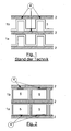
- FIG. 1 shows the passages 1a and 1b of a plate heat exchanger according to the prior art.
- a wave-shaped structure 3 which was made of a bent sheet metal.
- the adjacent passages 1 a and 1 b are separated by the separating plate 2 from each other.
- solder is applied. By soldering these solder joints, the entire heat exchanger is connected together. If two media for heat exchange under pressure are fed into the passages 1a and 1b, the entire passage 1a, 1b is under pressure. The pressure acts primarily on the connection points 4 between wave-shaped structure 3 and separating plate. 2
- FIG. 2 shows the passages 1 a and 1 b of an embodiment of the plate heat exchanger according to the invention.
- the passages 1a and 1b have a plurality of interconnected hollow profiles 5, which have a rectangular cross-section.
- the hollow profiles are connected in each case at the contact points 4 via solder with the separating plates 2.
- the contact surface and thus the connecting surface between the separating plate 2 and the structure of the passages 1a and 1b are significantly increased compared to the prior art.
- essentially only the hollow profiles 5 are under pressure. In a heat exchange between two media in the adjacent passages 1a and 1b, therefore, only the profiles 5 are under the high pressure of the media.
- the junction 4 between the hollow sections 5 and the separating plates 2 is not exposed to pressure.
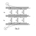
- FIG. 3 shows the passages 1a and 1b of a further embodiment of the plate heat exchanger according to the invention.
- the passages 1a and 1b have a
- the double-T profiles are connected at the contact points 4 via solder with the dividers 2.
- the contact surface and thus the connecting surface between separating plate 2 and the structure of the passages 1a and 1b are significantly increased compared to the prior art.
- essentially only the spaces between the double-T-profiles 6 are under pressure. In a heat exchange between two media in the adjacent passages 1a and 1b, therefore, only the double-T-profiles 6 are under the high pressure of the media.
- the connection point 4 between the double-T-profiles 6 and the separating plates 2 is not exposed to pressure.
Landscapes
- Engineering & Computer Science (AREA)
- Physics & Mathematics (AREA)
- Thermal Sciences (AREA)
- Mechanical Engineering (AREA)
- General Engineering & Computer Science (AREA)
- Geometry (AREA)
- Heat-Exchange Devices With Radiators And Conduit Assemblies (AREA)
- Separation By Low-Temperature Treatments (AREA)
Applications Claiming Priority (1)
| Application Number | Priority Date | Filing Date | Title |
|---|---|---|---|
| DE102009018247A DE102009018247A1 (de) | 2009-04-21 | 2009-04-21 | Plattenwärmeaustauscher mit Profilen |
Publications (2)
| Publication Number | Publication Date |
|---|---|
| EP2244045A2 true EP2244045A2 (fr) | 2010-10-27 |
| EP2244045A3 EP2244045A3 (fr) | 2013-03-27 |
Family
ID=42341411
Family Applications (1)
| Application Number | Title | Priority Date | Filing Date |
|---|---|---|---|
| EP10003998A Withdrawn EP2244045A3 (fr) | 2009-04-21 | 2010-04-15 | Échangeur thermique à plaques doté de profilés |
Country Status (5)
| Country | Link |
|---|---|
| US (1) | US20100263846A1 (fr) |
| EP (1) | EP2244045A3 (fr) |
| JP (1) | JP2010256006A (fr) |
| CN (1) | CN101871739A (fr) |
| DE (1) | DE102009018247A1 (fr) |
Families Citing this family (10)
| Publication number | Priority date | Publication date | Assignee | Title |
|---|---|---|---|---|
| DE102009048103A1 (de) | 2009-10-02 | 2011-04-07 | Linde Aktiengesellschaft | Wärmetauscher |
| US8995131B2 (en) | 2011-08-29 | 2015-03-31 | Aerovironment, Inc. | Heat transfer system for aircraft structures |
| US9756764B2 (en) | 2011-08-29 | 2017-09-05 | Aerovironment, Inc. | Thermal management system for an aircraft avionics bay |
| CN103453788A (zh) * | 2013-08-30 | 2013-12-18 | 南京威安新材料科技有限公司 | 一种气体板式换热器 |
| US20180045471A1 (en) * | 2015-03-05 | 2018-02-15 | Linde Aktiengesellschaft | 3d-printed heating surface element for a plate heat exchanger |
| EP3359902B2 (fr) | 2015-10-08 | 2023-06-28 | Linde GmbH | Procédé de fabrication d'une lamelle et un échangeur de chaleur à plaque avec une lamelle fabriquée à l'aide d'un tel procédé |
| US20200166293A1 (en) * | 2018-11-27 | 2020-05-28 | Hamilton Sundstrand Corporation | Weaved cross-flow heat exchanger and method of forming a heat exchanger |
| WO2020174169A1 (fr) * | 2019-02-25 | 2020-09-03 | L'air Liquide, Societe Anonyme Pour L'etude Et L'exploitation Des Procedes Georges Claude | Appareil d'échange de chaleur et de matière |
| CN112524793B (zh) * | 2019-09-17 | 2022-05-24 | 广东美的生活电器制造有限公司 | 液体处理装置 |
| US12510299B2 (en) * | 2020-12-02 | 2025-12-30 | Shanghai Xingye Materials Technology Co., Ltd. | Spiral heat exchanger and heat exchange device |
Citations (1)
| Publication number | Priority date | Publication date | Assignee | Title |
|---|---|---|---|---|
| DE10343107A1 (de) | 2002-10-01 | 2004-04-15 | Nordon Cryogenie Snc | Flügel für Plattenwärmetauscher, Verfahren zur Herstellung eines derartigen Flügels und Wärmetauscher mit einem derartigen Flügel |
Family Cites Families (11)
| Publication number | Priority date | Publication date | Assignee | Title |
|---|---|---|---|---|
| US2566310A (en) * | 1946-01-22 | 1951-09-04 | Hydrocarbon Research Inc | Tray type heat exchanger |
| US2634958A (en) * | 1948-12-03 | 1953-04-14 | Modine Mfg Co | Heat exchanger |
| US2874941A (en) * | 1955-09-06 | 1959-02-24 | Air Preheater | Brazed extended surface heat exchanger |
| FR1524141A (fr) * | 1967-01-31 | 1968-05-10 | Brissonneau & Lotz | Echangeurs plans pour le traitement de produits dont les dépôts adhèrent fortement aux parois |
| FR1580856A (fr) * | 1968-02-05 | 1969-09-12 | ||
| US3889744A (en) * | 1972-04-20 | 1975-06-17 | Owens Illinois Inc | Recuperator structures and method of making same |
| DE3146088A1 (de) * | 1981-11-20 | 1983-05-26 | Linde Ag, 6200 Wiesbaden | "plattenwaermetauscher" |
| JPS6245583U (fr) * | 1985-09-05 | 1987-03-19 | ||
| JPS6252788U (fr) * | 1985-09-11 | 1987-04-02 | ||
| DE10151238A1 (de) * | 2001-10-17 | 2003-04-30 | Autokuehler Gmbh & Co Kg | Kältemittel/Luft-Wärmeaustauschernetz |
| CN1448914A (zh) * | 2002-04-04 | 2003-10-15 | 得理电子(上海)有限公司 | 数码乐器的简谱输入法 |
-
2009
- 2009-04-21 DE DE102009018247A patent/DE102009018247A1/de not_active Withdrawn
-
2010
- 2010-04-15 EP EP10003998A patent/EP2244045A3/fr not_active Withdrawn
- 2010-04-19 CN CN201010164831A patent/CN101871739A/zh active Pending
- 2010-04-20 US US12/763,587 patent/US20100263846A1/en not_active Abandoned
- 2010-04-21 JP JP2010098159A patent/JP2010256006A/ja active Pending
Patent Citations (1)
| Publication number | Priority date | Publication date | Assignee | Title |
|---|---|---|---|---|
| DE10343107A1 (de) | 2002-10-01 | 2004-04-15 | Nordon Cryogenie Snc | Flügel für Plattenwärmetauscher, Verfahren zur Herstellung eines derartigen Flügels und Wärmetauscher mit einem derartigen Flügel |
Also Published As
| Publication number | Publication date |
|---|---|
| US20100263846A1 (en) | 2010-10-21 |
| EP2244045A3 (fr) | 2013-03-27 |
| DE102009018247A1 (de) | 2010-10-28 |
| CN101871739A (zh) | 2010-10-27 |
| JP2010256006A (ja) | 2010-11-11 |
Similar Documents
| Publication | Publication Date | Title |
|---|---|---|
| EP2244045A2 (fr) | Échangeur thermique à plaques doté de profilés | |
| EP3531055B1 (fr) | Échangeur de chaleur à plaques et son procédé de fabrication | |
| EP2843348B1 (fr) | Échangeur de chaleur à plaques doté de blocs d'échangeur de chaleur reliés par une mousse métallique | |
| DE60111469T3 (de) | Wärmetauscher und Verfahren zu dessen Herstellung | |
| DE3752324T2 (de) | Kondensator | |
| DE69513824T2 (de) | Plattenwärmetauscher mit drei kreisläufen | |
| EP3039367B1 (fr) | Procédé de fabrication d'un échangeur de chaleur à plaques avec plusieurs blocs d'échangeur de chaleur reliés par des supports étamés | |
| EP2645037B1 (fr) | Échangeur thermique à plaques avec plusieurs modules liés par un ruban de tôle | |
| DE102007022103A1 (de) | Selbstbrechende Seitenplatten für einen Kühler | |
| EP2645038B1 (fr) | Échangeur thermique à plaques avec plusieurs modules liés avec des profilés | |
| EP1154218B1 (fr) | Echangeur de chaleur à plaques | |
| DE112005001295T5 (de) | Wärmetauscher | |
| DE102006059234A1 (de) | Wärmetauscher | |
| EP3507046B1 (fr) | Procede de fabrication d'un bloc d'echangeur de chaleur a plaques consistant en l'application ciblee de materiau a braser, en particulier sur des ailettes et barres laterales | |
| DE102007001430A1 (de) | Wärmetauscher | |
| DE102009048103A1 (de) | Wärmetauscher | |
| EP3209452B1 (fr) | Procédé de fabrication d'un échangeur thermique à plaques en employant deux soudures | |
| EP4584550A1 (fr) | Échangeur de chaleur | |
| DE102017125004A1 (de) | Verfahren zur Herstellung eines Kühlprofils für ein Batteriemodul | |
| DE102020007618A1 (de) | Verfahren zur Herstellung eines Rippen-Platten-Wärmetauschers | |
| DE19846347A1 (de) | Wärmeaustauscher aus Aluminium oder einer Aluminium-Legierung | |
| DE102014006331A1 (de) | Plattenwärmetauscher und Verfahren zur Herstellung eines Plattenwärmetauschers | |
| DE102021131552B3 (de) | Verfahren zur Herstellung eines Flachrohrs | |
| DE102019110262A1 (de) | Platten-Rippen-Wärmeübertrager | |
| WO2008037309A1 (fr) | échangeur de chaleur |
Legal Events
| Date | Code | Title | Description |
|---|---|---|---|
| PUAI | Public reference made under article 153(3) epc to a published international application that has entered the european phase |
Free format text: ORIGINAL CODE: 0009012 |
|
| AK | Designated contracting states |
Kind code of ref document: A2 Designated state(s): AT BE BG CH CY CZ DE DK EE ES FI FR GB GR HR HU IE IS IT LI LT LU LV MC MK MT NL NO PL PT RO SE SI SK SM TR |
|
| AX | Request for extension of the european patent |
Extension state: AL BA ME RS |
|
| PUAL | Search report despatched |
Free format text: ORIGINAL CODE: 0009013 |
|
| AK | Designated contracting states |
Kind code of ref document: A3 Designated state(s): AT BE BG CH CY CZ DE DK EE ES FI FR GB GR HR HU IE IS IT LI LT LU LV MC MK MT NL NO PL PT RO SE SI SK SM TR |
|
| AX | Request for extension of the european patent |
Extension state: AL BA ME RS |
|
| RIC1 | Information provided on ipc code assigned before grant |
Ipc: F28D 9/00 20060101AFI20130215BHEP Ipc: F28F 1/04 20060101ALI20130215BHEP Ipc: F28F 3/02 20060101ALI20130215BHEP |
|
| STAA | Information on the status of an ep patent application or granted ep patent |
Free format text: STATUS: THE APPLICATION IS DEEMED TO BE WITHDRAWN |
|
| 18D | Application deemed to be withdrawn |
Effective date: 20130928 |