EP2645038B1 - Échangeur thermique à plaques avec plusieurs modules liés avec des profilés - Google Patents
Échangeur thermique à plaques avec plusieurs modules liés avec des profilés Download PDFInfo
- Publication number
- EP2645038B1 EP2645038B1 EP12004195.9A EP12004195A EP2645038B1 EP 2645038 B1 EP2645038 B1 EP 2645038B1 EP 12004195 A EP12004195 A EP 12004195A EP 2645038 B1 EP2645038 B1 EP 2645038B1
- Authority
- EP
- European Patent Office
- Prior art keywords
- contact surface
- fastened
- pair
- shaped
- modules
- Prior art date
- Legal status (The legal status is an assumption and is not a legal conclusion. Google has not performed a legal analysis and makes no representation as to the accuracy of the status listed.)
- Not-in-force
Links
- 238000005476 soldering Methods 0.000 claims description 3
- 238000003466 welding Methods 0.000 claims description 3
- 238000004026 adhesive bonding Methods 0.000 claims description 2
- 238000000465 moulding Methods 0.000 description 25
- 238000004519 manufacturing process Methods 0.000 description 15
- 238000000034 method Methods 0.000 description 6
- 229910052782 aluminium Inorganic materials 0.000 description 4
- XAGFODPZIPBFFR-UHFFFAOYSA-N aluminium Chemical compound [Al] XAGFODPZIPBFFR-UHFFFAOYSA-N 0.000 description 4
- 238000005219 brazing Methods 0.000 description 2
- 238000009826 distribution Methods 0.000 description 2
- VNWKTOKETHGBQD-UHFFFAOYSA-N methane Chemical compound C VNWKTOKETHGBQD-UHFFFAOYSA-N 0.000 description 2
- 238000007493 shaping process Methods 0.000 description 2
- 230000008646 thermal stress Effects 0.000 description 2
- RYGMFSIKBFXOCR-UHFFFAOYSA-N Copper Chemical compound [Cu] RYGMFSIKBFXOCR-UHFFFAOYSA-N 0.000 description 1
- VGGSQFUCUMXWEO-UHFFFAOYSA-N Ethene Chemical compound C=C VGGSQFUCUMXWEO-UHFFFAOYSA-N 0.000 description 1
- 239000005977 Ethylene Substances 0.000 description 1
- 238000010276 construction Methods 0.000 description 1
- 229910052802 copper Inorganic materials 0.000 description 1
- 239000010949 copper Substances 0.000 description 1
- 238000005520 cutting process Methods 0.000 description 1
- 238000006073 displacement reaction Methods 0.000 description 1
- 229910052751 metal Inorganic materials 0.000 description 1
- 239000002184 metal Substances 0.000 description 1
- 239000003345 natural gas Substances 0.000 description 1
- 238000005192 partition Methods 0.000 description 1
- 238000002360 preparation method Methods 0.000 description 1
- 238000000926 separation method Methods 0.000 description 1
- 229910000679 solder Inorganic materials 0.000 description 1
- 229910001220 stainless steel Inorganic materials 0.000 description 1
- 239000010935 stainless steel Substances 0.000 description 1
Images




Classifications
-
- F—MECHANICAL ENGINEERING; LIGHTING; HEATING; WEAPONS; BLASTING
- F28—HEAT EXCHANGE IN GENERAL
- F28D—HEAT-EXCHANGE APPARATUS, NOT PROVIDED FOR IN ANOTHER SUBCLASS, IN WHICH THE HEAT-EXCHANGE MEDIA DO NOT COME INTO DIRECT CONTACT
- F28D9/00—Heat-exchange apparatus having stationary plate-like or laminated conduit assemblies for both heat-exchange media, the media being in contact with different sides of a conduit wall
- F28D9/0031—Heat-exchange apparatus having stationary plate-like or laminated conduit assemblies for both heat-exchange media, the media being in contact with different sides of a conduit wall the conduits for one heat-exchange medium being formed by paired plates touching each other
- F28D9/0043—Heat-exchange apparatus having stationary plate-like or laminated conduit assemblies for both heat-exchange media, the media being in contact with different sides of a conduit wall the conduits for one heat-exchange medium being formed by paired plates touching each other the plates having openings therein for circulation of at least one heat-exchange medium from one conduit to another
- F28D9/0056—Heat-exchange apparatus having stationary plate-like or laminated conduit assemblies for both heat-exchange media, the media being in contact with different sides of a conduit wall the conduits for one heat-exchange medium being formed by paired plates touching each other the plates having openings therein for circulation of at least one heat-exchange medium from one conduit to another with U-flow or serpentine-flow inside conduits; with centrally arranged openings on the plates
-
- F—MECHANICAL ENGINEERING; LIGHTING; HEATING; WEAPONS; BLASTING
- F25—REFRIGERATION OR COOLING; COMBINED HEATING AND REFRIGERATION SYSTEMS; HEAT PUMP SYSTEMS; MANUFACTURE OR STORAGE OF ICE; LIQUEFACTION SOLIDIFICATION OF GASES
- F25J—LIQUEFACTION, SOLIDIFICATION OR SEPARATION OF GASES OR GASEOUS OR LIQUEFIED GASEOUS MIXTURES BY PRESSURE AND COLD TREATMENT OR BY BRINGING THEM INTO THE SUPERCRITICAL STATE
- F25J5/00—Arrangements of cold exchangers or cold accumulators in separation or liquefaction plants
- F25J5/002—Arrangements of cold exchangers or cold accumulators in separation or liquefaction plants for continuously recuperating cold, i.e. in a so-called recuperative heat exchanger
-
- F—MECHANICAL ENGINEERING; LIGHTING; HEATING; WEAPONS; BLASTING
- F28—HEAT EXCHANGE IN GENERAL
- F28D—HEAT-EXCHANGE APPARATUS, NOT PROVIDED FOR IN ANOTHER SUBCLASS, IN WHICH THE HEAT-EXCHANGE MEDIA DO NOT COME INTO DIRECT CONTACT
- F28D9/00—Heat-exchange apparatus having stationary plate-like or laminated conduit assemblies for both heat-exchange media, the media being in contact with different sides of a conduit wall
- F28D9/0062—Heat-exchange apparatus having stationary plate-like or laminated conduit assemblies for both heat-exchange media, the media being in contact with different sides of a conduit wall the conduits for one heat-exchange medium being formed by spaced plates with inserted elements
- F28D9/0068—Heat-exchange apparatus having stationary plate-like or laminated conduit assemblies for both heat-exchange media, the media being in contact with different sides of a conduit wall the conduits for one heat-exchange medium being formed by spaced plates with inserted elements with means for changing flow direction of one heat exchange medium, e.g. using deflecting zones
-
- F—MECHANICAL ENGINEERING; LIGHTING; HEATING; WEAPONS; BLASTING
- F28—HEAT EXCHANGE IN GENERAL
- F28F—DETAILS OF HEAT-EXCHANGE AND HEAT-TRANSFER APPARATUS, OF GENERAL APPLICATION
- F28F9/00—Casings; Header boxes; Auxiliary supports for elements; Auxiliary members within casings
- F28F9/001—Casings in the form of plate-like arrangements; Frames enclosing a heat exchange core
-
- F—MECHANICAL ENGINEERING; LIGHTING; HEATING; WEAPONS; BLASTING
- F28—HEAT EXCHANGE IN GENERAL
- F28F—DETAILS OF HEAT-EXCHANGE AND HEAT-TRANSFER APPARATUS, OF GENERAL APPLICATION
- F28F9/00—Casings; Header boxes; Auxiliary supports for elements; Auxiliary members within casings
- F28F9/007—Auxiliary supports for elements
- F28F9/0075—Supports for plates or plate assemblies
-
- F—MECHANICAL ENGINEERING; LIGHTING; HEATING; WEAPONS; BLASTING
- F25—REFRIGERATION OR COOLING; COMBINED HEATING AND REFRIGERATION SYSTEMS; HEAT PUMP SYSTEMS; MANUFACTURE OR STORAGE OF ICE; LIQUEFACTION SOLIDIFICATION OF GASES
- F25J—LIQUEFACTION, SOLIDIFICATION OR SEPARATION OF GASES OR GASEOUS OR LIQUEFIED GASEOUS MIXTURES BY PRESSURE AND COLD TREATMENT OR BY BRINGING THEM INTO THE SUPERCRITICAL STATE
- F25J2290/00—Other details not covered by groups F25J2200/00 - F25J2280/00
- F25J2290/32—Details on header or distribution passages of heat exchangers, e.g. of reboiler-condenser or plate heat exchangers
-
- F—MECHANICAL ENGINEERING; LIGHTING; HEATING; WEAPONS; BLASTING
- F25—REFRIGERATION OR COOLING; COMBINED HEATING AND REFRIGERATION SYSTEMS; HEAT PUMP SYSTEMS; MANUFACTURE OR STORAGE OF ICE; LIQUEFACTION SOLIDIFICATION OF GASES
- F25J—LIQUEFACTION, SOLIDIFICATION OR SEPARATION OF GASES OR GASEOUS OR LIQUEFIED GASEOUS MIXTURES BY PRESSURE AND COLD TREATMENT OR BY BRINGING THEM INTO THE SUPERCRITICAL STATE
- F25J2290/00—Other details not covered by groups F25J2200/00 - F25J2280/00
- F25J2290/42—Modularity, pre-fabrication of modules, assembling and erection, horizontal layout, i.e. plot plan, and vertical arrangement of parts of the cryogenic unit, e.g. of the cold box
-
- F—MECHANICAL ENGINEERING; LIGHTING; HEATING; WEAPONS; BLASTING
- F25—REFRIGERATION OR COOLING; COMBINED HEATING AND REFRIGERATION SYSTEMS; HEAT PUMP SYSTEMS; MANUFACTURE OR STORAGE OF ICE; LIQUEFACTION SOLIDIFICATION OF GASES
- F25J—LIQUEFACTION, SOLIDIFICATION OR SEPARATION OF GASES OR GASEOUS OR LIQUEFIED GASEOUS MIXTURES BY PRESSURE AND COLD TREATMENT OR BY BRINGING THEM INTO THE SUPERCRITICAL STATE
- F25J2290/00—Other details not covered by groups F25J2200/00 - F25J2280/00
- F25J2290/50—Arrangement of multiple equipments fulfilling the same process step in parallel
-
- F—MECHANICAL ENGINEERING; LIGHTING; HEATING; WEAPONS; BLASTING
- F28—HEAT EXCHANGE IN GENERAL
- F28F—DETAILS OF HEAT-EXCHANGE AND HEAT-TRANSFER APPARATUS, OF GENERAL APPLICATION
- F28F3/00—Plate-like or laminated elements; Assemblies of plate-like or laminated elements
- F28F3/08—Elements constructed for building-up into stacks, e.g. capable of being taken apart for cleaning
- F28F3/083—Elements constructed for building-up into stacks, e.g. capable of being taken apart for cleaning capable of being taken apart
-
- F—MECHANICAL ENGINEERING; LIGHTING; HEATING; WEAPONS; BLASTING
- F28—HEAT EXCHANGE IN GENERAL
- F28F—DETAILS OF HEAT-EXCHANGE AND HEAT-TRANSFER APPARATUS, OF GENERAL APPLICATION
- F28F9/00—Casings; Header boxes; Auxiliary supports for elements; Auxiliary members within casings
- F28F9/26—Arrangements for connecting different sections of heat-exchange elements, e.g. of radiators
Definitions
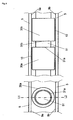
- Brazed plate heat exchangers made of aluminum are used in numerous systems at various pressures and temperatures. They are used for example in the separation of air, the liquefaction of natural gas or in plants for the production of ethylene.
- the in FIG. 1 illustrated plate heat exchanger 1 is used to heat exchange five different process streams A, B, C, D and E.
- the heat exchanger 1 is block-shaped and equipped with a variety of means 6 for supply and discharge of the individual process media. These means 6 are described below and in the context of this application referred to as nozzle.
- the heat exchanger also has a plurality of means 7 for distributing and collecting the individual process streams A, B, C, D and E, which are referred to below and in the context of this application as headers.
- the plate heat exchanger 1 consists of a plurality of stack-shaped arranged passages 3, which are separated by partitions 4 from each other.
- the various media flow.
- the heat exchange takes place indirectly via the heat contact, which is produced by the cover plates 5 and by the wave-shaped structure arranged in the passages (hereinafter referred to as fins in the context of this application).
- the individual media A, B, C, D and E are guided in the header 7 and distributed to the respectively provided, stacked passages 3.
- distributor fins 2 In the entrance area of the passages there are so-called distributor fins 2, which ensure an even distribution of the medium within the individual passages 3. The media thus flow transversely to the shaft direction of the fins 3 through the passages 3.
- the fins 3 are connected to the baffles 4, whereby an intensive mecanical modifier is produced. This allows a heat exchange between two different media that flow in adjacent passages 3. As seen in the flow direction at the end of the passage are similar distributor fins 2, which lead the media from the passages in the header 7, where they are collected and withdrawn through the nozzle 6. The individual passages 3 are completed by so-called sidebars 8 to the outside. The entire heat exchanger block is limited by cover plates 5 to the outside.
- Such plate heat exchangers are ideal for heat exchange of at least 2 media. By appropriate construction, however, as in FIG. 1 shown, even more than 2 media participate in the heat exchange. This allows a very effective process management and effective heat and cold utilization.
- Such plate heat exchangers are brazed, for example, aluminum.
- the individual passages with the fins, distributor fins, cover plates and sidebars are stacked on each other, provided with solder and brazed in an oven. On the resulting block then header and neck are welded.
- plate heat exchangers according to the prior art in such cases consist of at least two modules.
- a module is understood to be a heat exchanger block which is produced in a brazing furnace as described above.
- Several such modules are interconnected in the prior art and provided with common headers for distribution and collection of the heat exchanging media. The connection between two different modules of a plate heat exchanger takes place according to the prior art via sidebars.
- FIG. 1 illustrated plate heat exchanger consists of a module.
- a heat exchanger block as in FIG. 1 shown ie without header and nozzle, and welded to a second such heat exchanger block.
- cover plate 5 On the cover plate 5 sidebars are welded along the edges of the cover plate.
- the second module, which is to be connected to the first module, is arranged such that the two immediately adjacent sides of the two modules each have the same cover plates.
- the surface which is formed by a cover plate, which is immediately adjacent to another module, is referred to below as the contact surface. To connect the cover plate with the sidebars on the cover plate of the immediately adjacent module is welded.
- the sidebars therefore form according to the prior art, virtually a frame on the cover plate.
- This frame is welded to the cover plate of the adjacent module and made such a connection between two modules.
- the two connected modules thereby form a new heat exchanger block, which is larger than the actual geometry of the brazing oven allowed. In this way, any number of modules can be connected together to form an arbitrarily large heat exchanger block.
- two adjacent modules have at least one common header.
- the present invention has for its object to design a plate heat exchanger with at least two modules, as described above, such that the most rigid and firm connection between two immediately adjacent modules is made. For example, forces due to thermal stress between two modules should be minimized and the mechanical strength of the entire block consisting of at least two modules should be increased.
- a molding is understood to mean any type of profiles, rods, rods, tubes, pipe sections, half shells, spheres or the like.
- the moldings may be made of metal (e.g., stainless steel or copper), aluminum or plastic.
- molded parts in each case at least one molded part per module, are fastened to the two modules.
- the moldings are shaped and arranged so that the movement is prevented perpendicular to the contact surface.
- the molded parts thus prevent the movement of the two modules away from each other.
- Through the contact surfaces 2 levels are formed. According to the arrangement of the modules, these two planes are parallel.
- the shaping and positioning of the moldings allows the modules a maximum of movement in these planes (displacement, rotation). A movement with a component of motion that is perpendicular to these two levels is prevented by positioning and shaping of the molded parts.
- each contact surface has at least one molded part.
- a molded part on a contact surface forms a pair with a molded part of the contact surface of the neighboring module.
- the moldings are attached to the contact surfaces by soldering, gluing, welding and / or stapling.
- At least one U-shaped profile piece is fixed on each contact surface as a molded part with at least one side edge of the U-shaped profile on a contact surface, wherein the U-shaped profiles are arranged such that a fixed on a contact surface U-shaped Profile with a U-shaped profile attached to the other contact surface forms a pair, wherein the two openings of the U-shaped profiles of a pair show each other and thus form a cavity into which another molding can be inserted.
- At least one U-shaped profile is attached to the two contact surfaces.
- a U-shaped profile of a contact surface forms a pair with a U-shaped profile of the other contact surface.
- the U-shaped profiles are fastened with a long side of the U on the contact surface.
- the short side of the U is perpendicular to the contact surface.
- the two U-shaped profiles of a pair are oriented so that the open sides of the U face each other. Between the two openings of the U-shaped profiles of a pair so forms a cavity into which another additional molding can be inserted.
- the movement of the contact surfaces in a direction perpendicular to the contact surface, i. along the short side of the U prevented.
- the two attached to each different contact surfaces U-shaped profiles of a pair are prevented by the additional molding on the movement along the short side of the U, whereby the movement of the two modules is prevented perpendicular to the contact surface.
- a plurality of U-shaped profiles are arranged as pairs on the contact surfaces in this embodiment of the invention, wherein the arrangement is preferably distributed in parallel and at regular intervals over the entire contact surface.
- the length of the U-shaped profiles expediently corresponds to the length of a side edge of the contact surface.
- the two U-shaped profiles of a pair touch each other.
- the U-shaped profiles are arranged in the context of manufacturing tolerances on the contact surfaces such that between opposite long sides of the U of the U-shaped profiles of a pair a maximum gap is formed.
- At least one hollow profile is mounted on each contact surface, wherein the hollow profiles are arranged such that at least one attached to a contact surface hollow profile forms a pair attached to the other contact surface hollow profile, wherein the opening of the hollow profiles of a pair in a straight lines are arranged so that a further molded part can be inserted into the two cavities of the hollow profiles of a pair.
- hollow sections are arranged as a pair such that the openings of the hollow sections lie in a line.
- On each contact surface at least one hollow profile is arranged such that one sees through the opening of a hollow profile on a contact surface in the opening of the hollow profile on the other contact surface with which forms the hollow profile of a contact surface a pair.
- another molding is inserted in the resulting cavity. By this further molding, the movement of the two contact surfaces is prevented perpendicular to the contact surfaces.
- several pairs of hollow profiles are arranged behind one another in a line parallel to a side edge of the contact surfaces.
- a further molded part is fitted into the cavities of a plurality of pairs of hollow profiles arranged on a line.
- a multiplicity of several pairs arranged in a line are regularly distributed over the contact surfaces in parallel lines.
- the cross sections of the cavities of the hollow profiles may have any geometric shape, in particular rectangle, triangle, polygon, circle or ellipse.
- the cross sections can also change between arranged in different lines hollow sections.
- the additional molded parts, which are fitted into the cavities of the respective pair of hollow profiles expediently have a shape which corresponds to the cross section of the cavity.
- At least one pipe piece is mounted on each contact surface, wherein the pipe pieces are arranged such that at least one piece of pipe fastened on one contact surface forms a pair with a pipe piece fixed on the other contact surface, the opening of the pipe pieces of a pair in a straight line are arranged so that a another molding can be inserted into the two openings of the pipe sections of a pair.
- pipe section are preferably used analogously to the hollow profiles of the preceding embodiment.
- the description in the preceding paragraphs applies accordingly.
- the hollow profiles or pipe sections of a pair touch on the front side.
- the hollow sections or pipe sections are arranged in the context of manufacturing tolerances on the contact surfaces, that between the opposite end faces of the hollow sections or pipe sections of a pair a maximum gap is formed.
- the further molded part is a rod with a corresponding length and corresponding rectangular, polygonal, triangular or round cross-section.
- At least one U-shaped profile piece is fixed on each contact surface as a molded part with a side edge of the U-shaped profile on a contact surface, wherein the U-shaped profiles are arranged such that a fixed on a contact surface U-shaped Profile with a U-shaped profile attached to the other contact surface forms a pair, wherein the two U-shaped profiles of a pair are arranged such that the free side edge of a U-shaped profile is in the opening of the other U-shaped profile ,
- the movement of the contact surfaces is prevented perpendicular to the contact surface by molding and arrangement of the moldings themselves. Another molding is not necessary.
- the U-shaped profiles are arranged in pairs in this embodiment, that in each case the not fixed to a contact surface long side of the U of a U-shaped profile in the opening of the associated, mounted on the other contact surface, U-shaped profile of the pair ,
- the fixed on a contact surface U-shaped profile forms, so to speak, a guide rail for the long side of the U of a mounted on the other contact surface U-shaped profile and vice versa.
- the two U-shaped profiles of a pair interlock. That way, the movement becomes along the short side of the U of a U-shaped profile and thus prevents the movement perpendicular to the contact surface.
- the two U-shaped profiles of a pair touch each other.
- the U-shaped profiles are arranged in the context of manufacturing tolerances on the contact surfaces, that between adjacent sides of the U of the U-shaped profiles of a pair a maximum gap is formed.
- a plurality of U-shaped profiles are arranged as pairs on the contact surfaces, wherein the arrangement is preferably distributed in parallel and at regular intervals over the entire contact surface.
- the length of the U-shaped profiles expediently corresponds to the length of a side edge of the contact surface.
- At least one L-shaped profile piece is fixed on each contact surface as a molded part with a side edge of the L-shaped profile on a contact surface, wherein the L-shaped profiles are arranged such that an attached to a contact surface L-shaped Profile forms a pair with an attached to the other contact surface L-shaped profile, wherein the two L-shaped profiles of a pair are arranged such that the L of the L-shaped profile is fixed upside down on the contact surface and the two short Overlap sides of the L of the L-shaped profile.
- the attached on a contact surface L-shaped profile forms, so to speak, a guide rail for the short side of the L of an attached to the other contact surface L-shaped profile and vice versa. In this way, the movement along the long side of the L of an L-shaped profile and thus the movement perpendicular to the contact surface is prevented.
- the two L-shaped profiles of a pair touch each other.
- the L-shaped profiles are arranged in the context of manufacturing tolerances on the contact surfaces, that between adjacent sides of the L of the L-shaped profiles of a pair a maximum gap is formed.
- a plurality of L-shaped profiles are arranged as pairs on the contact surfaces, wherein the arrangement is preferably distributed in parallel and at regular intervals over the entire contact surface.
- the length of the L-shaped profiles expediently corresponds to the length of a side edge of the contact surface.
- This embodiment of the invention is similar to the previous embodiment, in which case L-shaped profiles are used instead of U-shaped profiles.
- the two L-shaped profiles of a pair are each mounted on the head on the corresponding contact surface.
- the long side of the L is thus fixed vertically standing on the contact surface, while the short side of the L is oriented parallel and spaced from the contact surface.
- the resulting cavity is in each case the short side of the L of the other L-shaped profile of the pair.
- the two L-shaped profiles of a pair almost interlock.
- short and long side of the L is used here only to explain the orientation of the L-shaped profile. Both sides can actually be the same length or in reverse length.
- the abovementioned embodiments of the invention can be combined as desired.
- the contact surfaces of two modules of a plate heat exchanger may have both pairs of U-shaped profiles, L-shaped profiles with or without additional molding, hollow sections and / or pipe sections.
- the present invention significantly improves the connection between two modules of a plate heat exchanger.
- a nearly planar connection of the two modules is achieved.
- FIG. 1 was already explained in the introduction to the description of the prior art.
- FIG. 2 shows the basic arrangement of two parallelepiped modules of a plate heat exchanger as described, with an embodiment of a plate heat exchanger according to the invention 1 consisting of two modules 1 a and 1 b is shown here.
- the two modules 1 a and 1 b are cuboid and each completed by cover plates 5 to the outside. Both modules 1 a and 1 b are arranged such that in each case the same size cover plates 9 a and 9 b are immediately adjacent.
- the two cover plates 9a and 9b form the contact surface between the two modules 1a and 1b of the plate heat exchanger 1.
- On these contact surfaces 9a and 9b are the molded parts in the FIGS. 3 to 6 attached embodiments of the invention explained.
- FIG. 3 shows an embodiment of the invention, are attached to the U-shaped profiles 20a and 20b on the contact surfaces 9a and 9b. Shown is a section, wherein the sectional plane perpendicular to the two contact surfaces 9a, 9b, as in FIG. 2 represented lies.
- the U-shaped profiles 20a are welded or soldered to a side edge 21a of the U-shaped profile via a welded or soldered connection 10 with the cover plate 5 on the contact surface 9a.
- the U-shaped profiles 20b are fastened with a side edge 21b via a welded joint 10 on the contact surface 9b.
- the U-shaped profiles are arranged so that their openings 22a and 22b face each other and thus form the cavity 23.
- a rod 50 is fitted with a rectangular cross section, which corresponds to the size of the cavity 23.
- the two U-shaped profiles 20a and 20b are arranged on the contact surfaces in such a way that they touch each other. Touching means in the context of this application, that forms a maximum gap between the opposing sides 21 a and 21 b of the U-shaped profiles 20 a and 20 b within the manufacturing tolerances of such profiles. Also, within the manufacturing tolerances, the rod 50 is fitted into the cavity 23 formed by the two U-shaped profiles 20a and 20b of a pair.
- a plurality of U-shaped profiles 20a, 20b regularly distributed over the two contact surfaces 9a and 9b, so that the space between the two contact surfaces 9a and 9b is regularly filled with spaced pairs of profiles.
- the U-shaped profiles 20a, 20b and the rectangular bars 50 have a length which corresponds approximately to the length of one of the side edges of the contact surfaces 9a, 9b.
- the individual U-shaped profiles 20a and 20b are first welded to the cover plates 5 of the modules 1a, 1b, which later form the contact surfaces 9a and 9b.
- the two modules 1 a, 1 b are then joined together at the contact surfaces.
- U-shaped profiles 20a, 20b thereby creates the cavity 23 between the U-shaped profiles 20a, 20b of a pair.
- the rectangular rods 50 are fitted and so the two modules 1 a and 1 b connected.
- the modules can then optionally be welded via sidebars 8 at the edges, as described in the prior art.
- FIG. 4 shows an embodiment of the invention, are attached to the blank pieces 30a, 30b on the contact surfaces 9a, 9b. Shown here are two sections, wherein the sectional planes perpendicular to the two contact surfaces 9a, 9b, as in FIG. 2 represented lie.
- the right-hand illustration shows a section of the cutting plane along L1-L2 of the left-hand illustration.
- Pipe pieces 30a and 30b are arranged in pairs on the contact surfaces 9a and 9b such that the openings 31a, 31b of the pipe sections 30a and 30b of a pair in one straight line lie. That is, one can thus simultaneously look through the opening 31 a in the pipe section 30 a and the opening 31 b in the pipe section 30 b of a pair.
- a round rod 51 is fitted in these two openings 31 a and 31 b.
- the movement of the two modules 1 a and 1 b in a direction perpendicular to the contact surfaces 9 a and 9 b is prevented by the round rod 51 in the respective pipe sections 30 a and 30 b fastened on the contact surfaces 9 a and 9 b.
- the relative movement of the modules 1 a, 1 b in the contact planes 9 a, 9 b is prevented at the same time.
- a plurality of pairs of pipe sections 30a, 30b are arranged one behind the other in a line, so that a line of several pairs 30a, 30b extends over the entire length of a side length of the contact surfaces 9a, 9b.
- a plurality of lines are distributed at regular intervals over the other side length of the contact surfaces 9a, 9b, so that the contact surfaces with a plurality of regularly arranged pairs of pipe sections 30a, 30b are filled.
- a corresponding round rod 51 is fitted, so that the openings 31 a, 31 b of the pipe sections 30 a, 30 b are filled by the rod 51. That
- the cross section of the rod 51 is selected such that the highest within the production tolerances a gap between the rod 51 and the inner wall of the pipe sections 30a, 30b forms.
- the pipe sections 30a, 30b of a pair are spaced from each other.
- the tube pieces 30a, 30b may be arranged so that the end faces touch (not shown).
- the preparation of this embodiment of a plate heat exchanger 1 is similar to the in FIG. 3 described embodiment.
- the individual pipe sections 30a, 30b are first welded to the cover plates 5 of the modules 1a, 1b, which later form the contact surfaces 9a and 9b.
- the two modules 1a, 1b are then joined together at the contact surfaces.
- the cavity in the openings 31a, 31b of the pipe sections 30a, 30b of a pair is formed by the pipe sections 30a, 30b arranged in pairs on the respective contact surfaces.
- the round bars 51 are fitted and so the two modules 1 a and 1 b connected.
- the modules can then optionally be welded on sidebars 8 at the edges as in the prior art.
- FIG. 5 shows an embodiment of the invention in which only U-shaped profiles 40a, 40b prevent the movement of the modules 1a, 1b perpendicular to the contact surfaces 9a, 9b without the additional additional moldings are used. Shown is a section analogous, wherein the sectional plane perpendicular to the two contact surfaces 9a, 9b, as in FIG. 2 represented lies.
- U-shaped profiles 40a, 40b with a side edge 41a, 41b by means of a welded joint 10 is attached on each contact surface 9a, 9b.
- the U-shaped profiles 40a, 40b are arranged such that a U-shaped profile 40a fastened on a contact surface 9a forms a pair with a U-shaped profile 40b fastened on the other contact surface 9b.
- the free side edges 42a, 42b (the side edges of the U-shaped profiles 40a, 40b, which are not welded to the contact surfaces 9a, 9b) of the U-shaped profiles 40a, 40b are located in the openings 43a, 43b of the other U shaped profile 40a, 40b.
- the U-shaped profile 40a fastened on a contact surface 9a forms, as it were, a guide rail for the long side 42b of the U of a U-shaped profile 40b fastened on the other contact surface 9b and vice versa. In this way, the movement along the short side of the U of the U-shaped profiles 40a, 40b and thus the movement perpendicular to the contact surfaces 9a, 9b is prevented.
- the two U-shaped profiles 40a, 40b of a pair touch each other.
- the U-shaped profiles 40a, 40b are arranged in the production tolerances on the contact surfaces 9a, 9b that between adjacent sides 42a, 42b, 43a, 43b of the U-shaped profiles 40a, 40b of a pair a maximum of a small gap arises.
- U-shaped profiles 40a, 40b regularly distributed over the two contact surfaces 9a and 9b, so that the space between the two contact surfaces 9a and 9b is regularly filled with spaced-apart profile pairs.
- the U-shaped profiles 40a, 40b have a length which corresponds approximately to the length of one of the side edges of the contact surfaces 9a, 9b.
- the individual U-shaped profiles 40a and 40b are first welded to the cover plates 5 of the modules 1a, 1b, which later form the contact surfaces 9a and 9b.
- the two modules 1 a, 1 b are then joined together at the contact surfaces, wherein the U-shaped profiles 40 a, 40 b are joined together, similar to the merging of two guide rail systems.
- the assembled modules 1 a and 1 b are then connected together.
- the modules can then optionally be welded on sidebars 8 at the edges as in the prior art.
- each contact surface at least one L-shaped profile piece 60a, 60b as a molded part with a side edge 61 a, 61 b of the L-shaped profile 60a, 60b mounted on a contact surface 9a, 9b, wherein the L-shaped profiles 60a, 60b are arranged such that an L-shaped profile 60a fastened on a contact surface 9a forms a pair with an L-shaped profile 60b fastened on the other contact surface 9b, the two L-shaped profiles 60a, 60b of a pair being arranged in such a way are that the L of the L-shaped profile 60a, 60b is fixed upside down on the contact surface 9a, 9b and the two short sides 62a, 62b of the L of the L-shaped profile 60a, 60b overlap.
- the L-shaped profile 60a fastened on a contact surface 9a forms, as it were, a guide rail for the short side 62b of the L of an L-shaped profile 60b fastened on the other contact surface 9b and vice versa. In this way, the movement along the long side 63a, 63b of the L of an L-shaped profile 60a, 60b and thus the movement perpendicular to the contact surface 9a, 9b is prevented.
- the two L-shaped profiles 60a, 60b of a pair touch each other.
- the L-shaped profiles 60a, 60b are arranged within the manufacturing tolerances on the contact surfaces 9a, 9b, that between adjacent sides 62a, 62b of the L of the L-shaped profiles 60a, 60b of a pair a maximum small gap arises.
- a plurality of L-shaped profiles 60a, 60b regularly distributed over the two contact surfaces 9a and 9b, so that the gap between the two contact surfaces 9a and 9b is regularly filled with spaced-apart profile pairs.
- the L-shaped profiles 60a, 60b have a length which corresponds approximately to the length of one of the side edges of the contact surfaces 9a, 9b
Landscapes
- Engineering & Computer Science (AREA)
- Physics & Mathematics (AREA)
- Mechanical Engineering (AREA)
- Thermal Sciences (AREA)
- General Engineering & Computer Science (AREA)
- Heat-Exchange Devices With Radiators And Conduit Assemblies (AREA)
- Details Of Heat-Exchange And Heat-Transfer (AREA)
Claims (10)
- Echangeur thermique à plaques (1) constitué d'au moins deux modules (1a, 1b)• chaque module (1a, 1b) comportant une pluralité de passages (3) disposés en forme de piles, qui sont traversés en alternance par des fluides échangeurs thermiques et qui sont séparés les uns des autres par des tôles séparatrices (4),• les modules (1a, 1b) étant globalement en forme de parallélépipèdes et étant délimités sur les faces extérieures par des tôles de recouvrement (5),• les modules (1a, 1b) étant disposés les uns à côté des autres de telle sorte qu'un côté (9a) rectangulaire d'un module (1a) en forme de parallélépipède soit directement voisin d'un côté (9b) rectangulaire correspondant d'un autre module (1b) en forme de parallélépipède,• les modules (1a, 1b) comportant des moyens (6) pour alimenter et pour évacuer les fluides échangeurs thermiques, ainsi que des moyens (7) (collecteur) pour distribuer et collecter les fluides échangeurs thermiques entre les ou hors des passages individuels (3), et• au moins deux modules (1a, 1b) comportant au moins un collecteur (7) commun, caractérisé en ce que• sur les deux tôles de recouvrement (5) qui forment les côtés (9a, 9b) respectivement directement voisins de deux modules (1a, 1b) voisins, désignés ci-dessous en tant que surfaces de contact (9a, 9b), est fixée chaque fois au moins une pièce moulée (20a, 20b, 30a, 30b, 40a, 40b, 60a, 60b),• les pièces moulées (40a, 40b, 60a, 60b) étant disposées et conformées de telle sorte que par au moins une pièce moulée (40a, 60a) sur une surface de contact (9a) et une pièce moulée (40b, 60b) sur l'autre surface de contact (9b) le déplacement des modules (1a, 1b) à la perpendiculaire de la surface de contact (9a, 9b) soit empêché ou• les pièces moulées (20a, 20b, 30a, 30b) étant disposées et conformées de telle sorte que par au moins une pièce moulée (20a, 30a) sur une surface de contact (9a) et une pièce moulée (20b, 30b) sur l'autre surface de contact (9b), ainsi que par au moins une pièce moulée (50, 51) supplémentaire, le déplacement des modules (1a, 1b) à la perpendiculaire de la surface de contact (9a, 9b) soit empêché.
- Echangeur thermique à plaques (1) selon la revendication 1, caractérisé en ce que les pièces moulées (20a, 20b, 30a, 30b, 40a, 40b, 60a, 60b) sont fixées sur les surfaces de contact (9a, 9b) par brasage, par collage, par soudage (10) et/ou par agrafage.
- Echangeur thermique à plaques (1) selon la revendication 1 ou la revendication 2, caractérisé en ce que sur chaque surface de contact (9a, 9b), par au moins une arête latérale (21a, 21b) du profilé en forme de U (20a, 20b), au moins une pièce profilée (20a, 20b) en forme de U est fixée en tant que pièce moulée sur une surface de contact (9a, 9b), les profilés en forme de U (20a, 20b) étant disposés de telle sorte qu'un profilé en forme de U (20a) fixé sur une surface de contact (9a) forme une paire avec un profilé en forme de U (20b) fixé sur l'autre surface de contact (9b), les deux orifices (22a, 22b) des profilés en forme de U (20a, 20b) d'une paire étant dirigés l'un vers l'autre et formant ainsi une cavité (23) dans laquelle peut être insérée une pièce moulée (50) supplémentaire.
- Echangeur thermique à plaques (1) selon la revendication 3, caractérisé en ce que les deux profilés en forme de U (20a, 20b) d'une paire se touchent.
- Echangeur thermique à plaques (1) selon l'une quelconque des revendications 1 à 3, caractérisé en ce que sur chaque surface de contact (9a, 9b) est fixé au moins un profilé creux, les profilés creux étant disposés de telle sorte qu'au moins un profilé creux fixé sur une surface de contact (9a) forme une paire avec un profilé creux fixé sur l'autre surface de contact (9b), les orifices des profilés creux d'une paire étant disposés sur une ligne droite, de telle sorte qu'une pièce moulée supplémentaire puisse être insérée dans les deux cavités des profilés creux d'une paire.
- Echangeur thermique à plaques (1) selon l'une quelconque des revendications 1 à 3, caractérisé en ce que sur chaque surface de contact (9a, 9b) est fixée au moins une pièce tubulaire (30a, 30b), les pièces tubulaires (30a, 30b) étant disposées de telle sorte qu'au moins une pièce tubulaire (30a) fixée sur une surface de contact (9a) forme une paire avec une pièce tubulaire (30b) fixée sur l'autre surface de contact (9b), les orifices (31a, 31b) des pièces tubulaires (30a, 30b) d'une paire étant disposés sur une ligne droite, de telle sorte qu'une pièce moulée (51) supplémentaire puisse être insérée dans les deux orifices (31a, 31b) des pièces tubulaires (30a, 30b) d'une paire.
- Echangeur thermique à plaques (1) selon la revendication 5 ou la revendication 6, caractérisé en ce que les profilés creux ou pièces tubulaires (30a, 30b) d'une paire se touchent sur la face frontale (31a, 31b).
- Echangeur thermique à plaques (1) selon l'une quelconque des revendications 3 à 7, caractérisé en ce que la pièce moulée supplémentaire est une barre (50, 51) de longueur correspondante et de section transversale rectangulaire (50), carrée, triangulaire ou ronde (51) correspondante.
- Echangeur thermique à plaques (1) selon l'une quelconque des revendications 1 à 8, caractérisé en ce que sur chaque surface de contact (9a, 9b), par une arête latérale (41a, 41b) du profilé en forme de U (40a, 40b), au moins une pièce profilée (40a, 40b) en forme de U est fixée en tant que pièce moulée sur une surface de contact (9a, 9b), les profilés en forme de U (40a, 40b) étant disposés de telle sorte qu'un profilé en forme de U (40a) fixé sur une surface de contact (9a) forme une paire avec un profilé en forme de U (40b) fixé sur l'autre surface de contact (9b), les deux profilés en forme de U (40a, 40b) d'une paire étant disposés de telle sorte que l'arête latérale libre (42a) de l'un des profilés en forme de U (40a) se trouve dans l'orifice (43b) de l'autre profilé en forme de U (40b).
- Echangeur thermique à plaques selon l'une quelconque des revendications 1 à 9, caractérisé en ce que sur chaque surface de contact (9a, 9b) est fixée par une arête latérale (61a, 61b) du profilé en forme de L (60a, 60b) sur une surface de contact (9a, 9b) au moins une pièce profilée (60a, 60b) en forme de L en tant que pièce moulée, les profilés en forme de L (60a, 60b) étant disposés de telle sorte qu'un profilé en forme de L (60a) fixé sur une surface de contact (9a) forme une paire avec un profilé en forme de L (60b) fixé sur l'autre surface de contact (9b), les deux profilés en forme de L (60a, 60b) d'une paire étant disposés de telle sorte que le L du profilé en forme de L (60a, 60b) soit fixé à l'envers sur la surface de contact (9a, 9b) et que les deux côtés courts (62a, 62b) du L du profilé en forme de L (60a, 60b) se chevauchent.
Applications Claiming Priority (1)
| Application Number | Priority Date | Filing Date | Title |
|---|---|---|---|
| DE102012006477A DE102012006477A1 (de) | 2012-03-29 | 2012-03-29 | Plattenwärmetauscher mit mehreren Modulen verbunden mit Profilen |
Publications (2)
| Publication Number | Publication Date |
|---|---|
| EP2645038A1 EP2645038A1 (fr) | 2013-10-02 |
| EP2645038B1 true EP2645038B1 (fr) | 2015-09-02 |
Family
ID=46317094
Family Applications (1)
| Application Number | Title | Priority Date | Filing Date |
|---|---|---|---|
| EP12004195.9A Not-in-force EP2645038B1 (fr) | 2012-03-29 | 2012-05-31 | Échangeur thermique à plaques avec plusieurs modules liés avec des profilés |
Country Status (5)
| Country | Link |
|---|---|
| US (1) | US10605536B2 (fr) |
| EP (1) | EP2645038B1 (fr) |
| JP (1) | JP6265614B2 (fr) |
| CN (1) | CN103363823B (fr) |
| DE (1) | DE102012006477A1 (fr) |
Families Citing this family (9)
| Publication number | Priority date | Publication date | Assignee | Title |
|---|---|---|---|---|
| EP2708840A1 (fr) * | 2012-09-18 | 2014-03-19 | Linde Aktiengesellschaft | Échangeur thermique à plaques avec un élément de liaison, notamment en T |
| EP2843348B1 (fr) * | 2013-08-29 | 2016-05-04 | Linde Aktiengesellschaft | Échangeur de chaleur à plaques doté de blocs d'échangeur de chaleur reliés par une mousse métallique |
| DE102014006331A1 (de) | 2014-04-30 | 2015-11-05 | Linde Aktiengesellschaft | Plattenwärmetauscher und Verfahren zur Herstellung eines Plattenwärmetauschers |
| JP2019510189A (ja) * | 2016-03-16 | 2019-04-11 | リンデ アクチエンゲゼルシャフトLinde Aktiengesellschaft | 成形部材間で管を液圧式に拡張することによる、熱交換器ブロックの全面的な結合部 |
| WO2020011398A1 (fr) | 2018-07-11 | 2020-01-16 | Linde Aktiengesellschaft | Échangeur de chaleur et procédé de fabrication d'un échangeur de chaleur |
| CZ2019252A3 (cs) * | 2019-04-24 | 2020-06-24 | Vysoká Škola Báňská - Technická Univerzita Ostrava | Rekuperační deskový výměník tepla |
| DE102020007618A1 (de) | 2020-01-30 | 2021-08-05 | Linde Gmbh | Verfahren zur Herstellung eines Rippen-Platten-Wärmetauschers |
| CN119630936A (zh) * | 2022-08-19 | 2025-03-14 | 林德有限责任公司 | 板式热交换器和方法 |
| PL248910B1 (pl) | 2023-11-17 | 2026-02-09 | Aic Spolka Akcyjna | Płytowy moduł wymiany ciepła |
Citations (6)
| Publication number | Priority date | Publication date | Assignee | Title |
|---|---|---|---|---|
| US3372453A (en) | 1965-03-22 | 1968-03-12 | Trane Co | Plate type heat exchanger and method of construction and repair |
| US3986549A (en) | 1975-07-14 | 1976-10-19 | Modine Manufacturing Company | Heat exchanger |
| WO1995018947A1 (fr) | 1994-01-04 | 1995-07-13 | Dierbeck Robert F | Echangeur thermique modulaire en aluminium extrude |
| US20050217832A1 (en) | 2003-11-27 | 2005-10-06 | Denso Corporation | Heat exchanger of a multiple type |
| EP1990596A1 (fr) | 2007-05-10 | 2008-11-12 | Behr France Hambach S.A.R.L. | Agencement de fixation des échangeurs de chaleur comprenant une collage |
| WO2011006613A2 (fr) | 2009-07-17 | 2011-01-20 | Bayer Technology Services Gmbh | Module de dispositif de transfert de chaleur et dispositifs de transfert de chaleur présentant une configuration compacte |
Family Cites Families (26)
| Publication number | Priority date | Publication date | Assignee | Title |
|---|---|---|---|---|
| US2184657A (en) * | 1936-04-10 | 1939-12-26 | Fred M Young | Heat exchanger |
| US2782009A (en) * | 1952-03-14 | 1957-02-19 | Gen Motors Corp | Heat exchangers |
| GB1083323A (en) * | 1964-03-25 | 1967-09-13 | English Electric Co Ltd | Dry cooling towers |
| US3633661A (en) * | 1970-08-14 | 1972-01-11 | Trane Co | Crossflow plate-type heat exchanger with barrier space |
| JPS5243151B2 (fr) * | 1972-06-06 | 1977-10-28 | ||
| US4297775A (en) * | 1980-05-08 | 1981-11-03 | The Trane Company | Method for joining two plate type heat exchanger core sections with an intermodular layer for improved heat transfer |
| DE3521914A1 (de) * | 1984-06-20 | 1986-01-02 | Showa Aluminum Corp., Sakai, Osaka | Waermetauscher in fluegelplattenbauweise |
| JPH036105U (fr) * | 1989-06-09 | 1991-01-22 | ||
| US5046554A (en) * | 1990-02-22 | 1991-09-10 | Calsonic International, Inc. | Cooling module |
| FR2665755B1 (fr) * | 1990-08-07 | 1993-06-18 | Air Liquide | Appareil de production d'azote. |
| US5197538A (en) * | 1991-04-22 | 1993-03-30 | Zexel Corporation | Heat exchanger apparatus having fluid coupled primary heat exchanger unit and auxiliary heat exchanger unit |
| JPH058247U (ja) * | 1991-07-12 | 1993-02-05 | 東洋ラジエーター株式会社 | エンジンルームに取付けられる複合型熱交換器 |
| US5219016A (en) * | 1992-06-15 | 1993-06-15 | General Motors Corporation | Radiator, condenser and fan shroud assembly |
| US6237676B1 (en) * | 1998-04-28 | 2001-05-29 | Denso Corporation | Heat exchanger for vehicle air conditioner |
| DE29909871U1 (de) * | 1999-06-02 | 2000-10-12 | Autokühler GmbH & Co. KG, 34369 Hofgeismar | Wärmeaustauscher, insbesondere Ölkühler |
| FR2798598B1 (fr) * | 1999-09-21 | 2002-05-24 | Air Liquide | Vaporiseur-condenseur a bain et appareil de distillation d'air correspondant |
| DE10201832A1 (de) * | 2002-01-18 | 2003-07-31 | Linde Ag | Plattenwärmetauscher |
| JP2005249332A (ja) * | 2004-03-05 | 2005-09-15 | Denso Corp | 複式熱交換器 |
| JP4148113B2 (ja) * | 2003-11-27 | 2008-09-10 | 株式会社デンソー | 熱交換器モジュール |
| JP2005156067A (ja) * | 2003-11-27 | 2005-06-16 | Denso Corp | 熱交換器モジュール |
| JP2006145165A (ja) * | 2004-11-24 | 2006-06-08 | Calsonic Kansei Corp | 複合型熱交換器 |
| DE102005043731A1 (de) * | 2005-09-14 | 2007-03-22 | Behr Industry Gmbh & Co. Kg | Wärmeübertrager |
| US7896064B2 (en) * | 2006-06-27 | 2011-03-01 | Tranter, Inc. | Plate-type heat exchanger |
| TWI337837B (en) * | 2007-06-08 | 2011-02-21 | Ama Precision Inc | Heat sink and modular heat sink |
| DE102008052875A1 (de) * | 2008-10-23 | 2010-04-29 | Linde Ag | Plattenwärmetauscher |
| US9022100B2 (en) * | 2010-11-17 | 2015-05-05 | Denso Marston Ltd. | Adjustable tank for bar-plate heat exchanger |
-
2012
- 2012-03-29 DE DE102012006477A patent/DE102012006477A1/de not_active Withdrawn
- 2012-05-31 EP EP12004195.9A patent/EP2645038B1/fr not_active Not-in-force
-
2013
- 2013-03-26 CN CN201310098761.0A patent/CN103363823B/zh active Active
- 2013-03-28 US US13/852,461 patent/US10605536B2/en active Active
- 2013-03-29 JP JP2013072666A patent/JP6265614B2/ja not_active Expired - Fee Related
Patent Citations (6)
| Publication number | Priority date | Publication date | Assignee | Title |
|---|---|---|---|---|
| US3372453A (en) | 1965-03-22 | 1968-03-12 | Trane Co | Plate type heat exchanger and method of construction and repair |
| US3986549A (en) | 1975-07-14 | 1976-10-19 | Modine Manufacturing Company | Heat exchanger |
| WO1995018947A1 (fr) | 1994-01-04 | 1995-07-13 | Dierbeck Robert F | Echangeur thermique modulaire en aluminium extrude |
| US20050217832A1 (en) | 2003-11-27 | 2005-10-06 | Denso Corporation | Heat exchanger of a multiple type |
| EP1990596A1 (fr) | 2007-05-10 | 2008-11-12 | Behr France Hambach S.A.R.L. | Agencement de fixation des échangeurs de chaleur comprenant une collage |
| WO2011006613A2 (fr) | 2009-07-17 | 2011-01-20 | Bayer Technology Services Gmbh | Module de dispositif de transfert de chaleur et dispositifs de transfert de chaleur présentant une configuration compacte |
Also Published As
| Publication number | Publication date |
|---|---|
| EP2645038A1 (fr) | 2013-10-02 |
| JP2013205009A (ja) | 2013-10-07 |
| JP6265614B2 (ja) | 2018-01-24 |
| US20130277027A1 (en) | 2013-10-24 |
| DE102012006477A1 (de) | 2013-10-02 |
| US10605536B2 (en) | 2020-03-31 |
| CN103363823A (zh) | 2013-10-23 |
| CN103363823B (zh) | 2017-03-01 |
Similar Documents
| Publication | Publication Date | Title |
|---|---|---|
| EP2645038B1 (fr) | Échangeur thermique à plaques avec plusieurs modules liés avec des profilés | |
| EP2843348B1 (fr) | Échangeur de chaleur à plaques doté de blocs d'échangeur de chaleur reliés par une mousse métallique | |
| EP2645037B2 (fr) | Échangeur thermique à plaques avec plusieurs modules liés par un ruban de tôle | |
| EP3265739B1 (fr) | Élément chauffant imprimé en 3d pour un échangeur de chaleur à plaques | |
| EP3359902B1 (fr) | Procédé de fabrication d'une lamelle et un échangeur de chaleur à plaque avec une lamelle fabriquée à l'aide d'un tel procédé | |
| DE2946804C2 (fr) | ||
| EP2859295B1 (fr) | Caloporteur | |
| EP3039367B1 (fr) | Procédé de fabrication d'un échangeur de chaleur à plaques avec plusieurs blocs d'échangeur de chaleur reliés par des supports étamés | |
| DE102008033302A1 (de) | Ermüdungsfester Plattenwärmetauscher | |
| DE102009033661A1 (de) | Wärmeübertragermodul und Wärmeübertrager in kompakter Bauweise | |
| EP2244045A2 (fr) | Échangeur thermique à plaques doté de profilés | |
| EP2710318A1 (fr) | Echangeur de chaleur à lamelles | |
| DE102008036614A1 (de) | Wärmetauscher | |
| EP3507046B1 (fr) | Procede de fabrication d'un bloc d'echangeur de chaleur a plaques consistant en l'application ciblee de materiau a braser, en particulier sur des ailettes et barres laterales | |
| DE2450739A1 (de) | Waermeaustauscher, insbesondere oelkuehler | |
| EP1770345B1 (fr) | Réseau d'échange de chaleur et échangeur de chaleur comprenant celui-ci | |
| EP1673583B1 (fr) | Refroidisseur d'air de suralimentation / refrigerant | |
| DE10151238A1 (de) | Kältemittel/Luft-Wärmeaustauschernetz | |
| DE102020000274A1 (de) | Verfahren zur Herstellung eines Rippen-Platten-Wärmetauschers | |
| EP3359900B1 (fr) | Barres laterales comprenant de structures de surfaces pour echangeur thermique a plaques | |
| DE102014006331A1 (de) | Plattenwärmetauscher und Verfahren zur Herstellung eines Plattenwärmetauschers | |
| EP1293743B1 (fr) | Bloc de tubes plats avec extrémités déformées pour échangeur de chaleur | |
| EP3746728B1 (fr) | Revêtement de surface isolant sur des échangeurs thermiques permettant de réduire les tensions thermiques | |
| DE19846347A1 (de) | Wärmeaustauscher aus Aluminium oder einer Aluminium-Legierung | |
| DE102016003179A1 (de) | Wärmetauscher bestehend aus einer Kapillarrohrmatte |
Legal Events
| Date | Code | Title | Description |
|---|---|---|---|
| PUAI | Public reference made under article 153(3) epc to a published international application that has entered the european phase |
Free format text: ORIGINAL CODE: 0009012 |
|
| AK | Designated contracting states |
Kind code of ref document: A1 Designated state(s): AL AT BE BG CH CY CZ DE DK EE ES FI FR GB GR HR HU IE IS IT LI LT LU LV MC MK MT NL NO PL PT RO RS SE SI SK SM TR |
|
| AX | Request for extension of the european patent |
Extension state: BA ME |
|
| 17P | Request for examination filed |
Effective date: 20140227 |
|
| RBV | Designated contracting states (corrected) |
Designated state(s): AL AT BE BG CH CY CZ DE DK EE ES FI FR GB GR HR HU IE IS IT LI LT LU LV MC MK MT NL NO PL PT RO RS SE SI SK SM TR |
|
| RIC1 | Information provided on ipc code assigned before grant |
Ipc: F28F 9/007 20060101ALI20140924BHEP Ipc: F28F 9/00 20060101ALI20140924BHEP Ipc: F28D 9/00 20060101AFI20140924BHEP Ipc: F25J 5/00 20060101ALN20140924BHEP |
|
| GRAP | Despatch of communication of intention to grant a patent |
Free format text: ORIGINAL CODE: EPIDOSNIGR1 |
|
| INTG | Intention to grant announced |
Effective date: 20141031 |
|
| GRAP | Despatch of communication of intention to grant a patent |
Free format text: ORIGINAL CODE: EPIDOSNIGR1 |
|
| RIC1 | Information provided on ipc code assigned before grant |
Ipc: F25J 5/00 20060101ALN20150304BHEP Ipc: F28D 9/00 20060101AFI20150304BHEP Ipc: F28F 9/007 20060101ALI20150304BHEP Ipc: F28F 9/00 20060101ALI20150304BHEP |
|
| INTG | Intention to grant announced |
Effective date: 20150323 |
|
| GRAS | Grant fee paid |
Free format text: ORIGINAL CODE: EPIDOSNIGR3 |
|
| GRAA | (expected) grant |
Free format text: ORIGINAL CODE: 0009210 |
|
| AK | Designated contracting states |
Kind code of ref document: B1 Designated state(s): AL AT BE BG CH CY CZ DE DK EE ES FI FR GB GR HR HU IE IS IT LI LT LU LV MC MK MT NL NO PL PT RO RS SE SI SK SM TR |
|
| REG | Reference to a national code |
Ref country code: GB Ref legal event code: FG4D Free format text: NOT ENGLISH |
|
| REG | Reference to a national code |
Ref country code: AT Ref legal event code: REF Ref document number: 746875 Country of ref document: AT Kind code of ref document: T Effective date: 20150915 Ref country code: CH Ref legal event code: EP |
|
| REG | Reference to a national code |
Ref country code: IE Ref legal event code: FG4D Free format text: LANGUAGE OF EP DOCUMENT: GERMAN |
|
| REG | Reference to a national code |
Ref country code: DE Ref legal event code: R096 Ref document number: 502012004354 Country of ref document: DE |
|
| PG25 | Lapsed in a contracting state [announced via postgrant information from national office to epo] |
Ref country code: FI Free format text: LAPSE BECAUSE OF FAILURE TO SUBMIT A TRANSLATION OF THE DESCRIPTION OR TO PAY THE FEE WITHIN THE PRESCRIBED TIME-LIMIT Effective date: 20150902 Ref country code: NO Free format text: LAPSE BECAUSE OF FAILURE TO SUBMIT A TRANSLATION OF THE DESCRIPTION OR TO PAY THE FEE WITHIN THE PRESCRIBED TIME-LIMIT Effective date: 20151202 Ref country code: GR Free format text: LAPSE BECAUSE OF FAILURE TO SUBMIT A TRANSLATION OF THE DESCRIPTION OR TO PAY THE FEE WITHIN THE PRESCRIBED TIME-LIMIT Effective date: 20151203 Ref country code: LT Free format text: LAPSE BECAUSE OF FAILURE TO SUBMIT A TRANSLATION OF THE DESCRIPTION OR TO PAY THE FEE WITHIN THE PRESCRIBED TIME-LIMIT Effective date: 20150902 Ref country code: LV Free format text: LAPSE BECAUSE OF FAILURE TO SUBMIT A TRANSLATION OF THE DESCRIPTION OR TO PAY THE FEE WITHIN THE PRESCRIBED TIME-LIMIT Effective date: 20150902 |
|
| REG | Reference to a national code |
Ref country code: LT Ref legal event code: MG4D Ref country code: NL Ref legal event code: MP Effective date: 20150902 |
|
| PG25 | Lapsed in a contracting state [announced via postgrant information from national office to epo] |
Ref country code: PL Free format text: LAPSE BECAUSE OF FAILURE TO SUBMIT A TRANSLATION OF THE DESCRIPTION OR TO PAY THE FEE WITHIN THE PRESCRIBED TIME-LIMIT Effective date: 20150902 Ref country code: ES Free format text: LAPSE BECAUSE OF FAILURE TO SUBMIT A TRANSLATION OF THE DESCRIPTION OR TO PAY THE FEE WITHIN THE PRESCRIBED TIME-LIMIT Effective date: 20150902 Ref country code: SE Free format text: LAPSE BECAUSE OF FAILURE TO SUBMIT A TRANSLATION OF THE DESCRIPTION OR TO PAY THE FEE WITHIN THE PRESCRIBED TIME-LIMIT Effective date: 20150902 Ref country code: RS Free format text: LAPSE BECAUSE OF FAILURE TO SUBMIT A TRANSLATION OF THE DESCRIPTION OR TO PAY THE FEE WITHIN THE PRESCRIBED TIME-LIMIT Effective date: 20150902 |
|
| REG | Reference to a national code |
Ref country code: FR Ref legal event code: PLFP Year of fee payment: 5 |
|
| PG25 | Lapsed in a contracting state [announced via postgrant information from national office to epo] |
Ref country code: SK Free format text: LAPSE BECAUSE OF FAILURE TO SUBMIT A TRANSLATION OF THE DESCRIPTION OR TO PAY THE FEE WITHIN THE PRESCRIBED TIME-LIMIT Effective date: 20150902 Ref country code: NL Free format text: LAPSE BECAUSE OF FAILURE TO SUBMIT A TRANSLATION OF THE DESCRIPTION OR TO PAY THE FEE WITHIN THE PRESCRIBED TIME-LIMIT Effective date: 20150902 Ref country code: IS Free format text: LAPSE BECAUSE OF FAILURE TO SUBMIT A TRANSLATION OF THE DESCRIPTION OR TO PAY THE FEE WITHIN THE PRESCRIBED TIME-LIMIT Effective date: 20160102 Ref country code: CZ Free format text: LAPSE BECAUSE OF FAILURE TO SUBMIT A TRANSLATION OF THE DESCRIPTION OR TO PAY THE FEE WITHIN THE PRESCRIBED TIME-LIMIT Effective date: 20150902 Ref country code: EE Free format text: LAPSE BECAUSE OF FAILURE TO SUBMIT A TRANSLATION OF THE DESCRIPTION OR TO PAY THE FEE WITHIN THE PRESCRIBED TIME-LIMIT Effective date: 20150902 Ref country code: IT Free format text: LAPSE BECAUSE OF FAILURE TO SUBMIT A TRANSLATION OF THE DESCRIPTION OR TO PAY THE FEE WITHIN THE PRESCRIBED TIME-LIMIT Effective date: 20150902 |
|
| PG25 | Lapsed in a contracting state [announced via postgrant information from national office to epo] |
Ref country code: PT Free format text: LAPSE BECAUSE OF FAILURE TO SUBMIT A TRANSLATION OF THE DESCRIPTION OR TO PAY THE FEE WITHIN THE PRESCRIBED TIME-LIMIT Effective date: 20160104 Ref country code: RO Free format text: LAPSE BECAUSE OF FAILURE TO SUBMIT A TRANSLATION OF THE DESCRIPTION OR TO PAY THE FEE WITHIN THE PRESCRIBED TIME-LIMIT Effective date: 20150902 |
|
| REG | Reference to a national code |
Ref country code: DE Ref legal event code: R026 Ref document number: 502012004354 Country of ref document: DE |
|
| PLBI | Opposition filed |
Free format text: ORIGINAL CODE: 0009260 |
|
| PLAF | Information modified related to communication of a notice of opposition and request to file observations + time limit |
Free format text: ORIGINAL CODE: EPIDOSCOBS2 |
|
| PLAX | Notice of opposition and request to file observation + time limit sent |
Free format text: ORIGINAL CODE: EPIDOSNOBS2 |
|
| 26 | Opposition filed |
Opponent name: L'AIR LIQUIDE, SOCIETE ANONYME POUR L'ETUDE ET L'E Effective date: 20160602 |
|
| PG25 | Lapsed in a contracting state [announced via postgrant information from national office to epo] |
Ref country code: BE Free format text: LAPSE BECAUSE OF NON-PAYMENT OF DUE FEES Effective date: 20160531 Ref country code: DK Free format text: LAPSE BECAUSE OF FAILURE TO SUBMIT A TRANSLATION OF THE DESCRIPTION OR TO PAY THE FEE WITHIN THE PRESCRIBED TIME-LIMIT Effective date: 20150902 Ref country code: SI Free format text: LAPSE BECAUSE OF FAILURE TO SUBMIT A TRANSLATION OF THE DESCRIPTION OR TO PAY THE FEE WITHIN THE PRESCRIBED TIME-LIMIT Effective date: 20150902 |
|
| PLBB | Reply of patent proprietor to notice(s) of opposition received |
Free format text: ORIGINAL CODE: EPIDOSNOBS3 |
|
| PG25 | Lapsed in a contracting state [announced via postgrant information from national office to epo] |
Ref country code: LU Free format text: LAPSE BECAUSE OF FAILURE TO SUBMIT A TRANSLATION OF THE DESCRIPTION OR TO PAY THE FEE WITHIN THE PRESCRIBED TIME-LIMIT Effective date: 20160531 |
|
| REG | Reference to a national code |
Ref country code: CH Ref legal event code: PL |
|
| PG25 | Lapsed in a contracting state [announced via postgrant information from national office to epo] |
Ref country code: LI Free format text: LAPSE BECAUSE OF NON-PAYMENT OF DUE FEES Effective date: 20160531 Ref country code: CH Free format text: LAPSE BECAUSE OF NON-PAYMENT OF DUE FEES Effective date: 20160531 |
|
| REG | Reference to a national code |
Ref country code: IE Ref legal event code: MM4A |
|
| REG | Reference to a national code |
Ref country code: FR Ref legal event code: PLFP Year of fee payment: 6 |
|
| PG25 | Lapsed in a contracting state [announced via postgrant information from national office to epo] |
Ref country code: IE Free format text: LAPSE BECAUSE OF NON-PAYMENT OF DUE FEES Effective date: 20160531 |
|
| PLCK | Communication despatched that opposition was rejected |
Free format text: ORIGINAL CODE: EPIDOSNREJ1 |
|
| REG | Reference to a national code |
Ref country code: DE Ref legal event code: R100 Ref document number: 502012004354 Country of ref document: DE |
|
| PLBN | Opposition rejected |
Free format text: ORIGINAL CODE: 0009273 |
|
| STAA | Information on the status of an ep patent application or granted ep patent |
Free format text: STATUS: OPPOSITION REJECTED |
|
| REG | Reference to a national code |
Ref country code: FR Ref legal event code: PLFP Year of fee payment: 7 |
|
| 27O | Opposition rejected |
Effective date: 20171211 |
|
| PG25 | Lapsed in a contracting state [announced via postgrant information from national office to epo] |
Ref country code: SM Free format text: LAPSE BECAUSE OF FAILURE TO SUBMIT A TRANSLATION OF THE DESCRIPTION OR TO PAY THE FEE WITHIN THE PRESCRIBED TIME-LIMIT Effective date: 20150902 Ref country code: HU Free format text: LAPSE BECAUSE OF FAILURE TO SUBMIT A TRANSLATION OF THE DESCRIPTION OR TO PAY THE FEE WITHIN THE PRESCRIBED TIME-LIMIT; INVALID AB INITIO Effective date: 20120531 Ref country code: CY Free format text: LAPSE BECAUSE OF FAILURE TO SUBMIT A TRANSLATION OF THE DESCRIPTION OR TO PAY THE FEE WITHIN THE PRESCRIBED TIME-LIMIT Effective date: 20150902 |
|
| PG25 | Lapsed in a contracting state [announced via postgrant information from national office to epo] |
Ref country code: HR Free format text: LAPSE BECAUSE OF FAILURE TO SUBMIT A TRANSLATION OF THE DESCRIPTION OR TO PAY THE FEE WITHIN THE PRESCRIBED TIME-LIMIT Effective date: 20150902 Ref country code: MC Free format text: LAPSE BECAUSE OF FAILURE TO SUBMIT A TRANSLATION OF THE DESCRIPTION OR TO PAY THE FEE WITHIN THE PRESCRIBED TIME-LIMIT Effective date: 20150902 Ref country code: TR Free format text: LAPSE BECAUSE OF FAILURE TO SUBMIT A TRANSLATION OF THE DESCRIPTION OR TO PAY THE FEE WITHIN THE PRESCRIBED TIME-LIMIT Effective date: 20150902 Ref country code: MK Free format text: LAPSE BECAUSE OF FAILURE TO SUBMIT A TRANSLATION OF THE DESCRIPTION OR TO PAY THE FEE WITHIN THE PRESCRIBED TIME-LIMIT Effective date: 20150902 Ref country code: MT Free format text: LAPSE BECAUSE OF FAILURE TO SUBMIT A TRANSLATION OF THE DESCRIPTION OR TO PAY THE FEE WITHIN THE PRESCRIBED TIME-LIMIT Effective date: 20150902 |
|
| REG | Reference to a national code |
Ref country code: AT Ref legal event code: MM01 Ref document number: 746875 Country of ref document: AT Kind code of ref document: T Effective date: 20170531 |
|
| PG25 | Lapsed in a contracting state [announced via postgrant information from national office to epo] |
Ref country code: BG Free format text: LAPSE BECAUSE OF FAILURE TO SUBMIT A TRANSLATION OF THE DESCRIPTION OR TO PAY THE FEE WITHIN THE PRESCRIBED TIME-LIMIT Effective date: 20150902 |
|
| PG25 | Lapsed in a contracting state [announced via postgrant information from national office to epo] |
Ref country code: AT Free format text: LAPSE BECAUSE OF NON-PAYMENT OF DUE FEES Effective date: 20170531 |
|
| PG25 | Lapsed in a contracting state [announced via postgrant information from national office to epo] |
Ref country code: AL Free format text: LAPSE BECAUSE OF FAILURE TO SUBMIT A TRANSLATION OF THE DESCRIPTION OR TO PAY THE FEE WITHIN THE PRESCRIBED TIME-LIMIT Effective date: 20150902 |
|
| PGFP | Annual fee paid to national office [announced via postgrant information from national office to epo] |
Ref country code: DE Payment date: 20190521 Year of fee payment: 8 |
|
| PGFP | Annual fee paid to national office [announced via postgrant information from national office to epo] |
Ref country code: FR Payment date: 20190410 Year of fee payment: 8 |
|
| PGFP | Annual fee paid to national office [announced via postgrant information from national office to epo] |
Ref country code: GB Payment date: 20190529 Year of fee payment: 8 |
|
| REG | Reference to a national code |
Ref country code: DE Ref legal event code: R081 Ref document number: 502012004354 Country of ref document: DE Owner name: LINDE GMBH, DE Free format text: FORMER OWNER: LINDE AKTIENGESELLSCHAFT, 80331 MUENCHEN, DE |
|
| REG | Reference to a national code |
Ref country code: DE Ref legal event code: R119 Ref document number: 502012004354 Country of ref document: DE |
|
| GBPC | Gb: european patent ceased through non-payment of renewal fee |
Effective date: 20200531 |
|
| PG25 | Lapsed in a contracting state [announced via postgrant information from national office to epo] |
Ref country code: GB Free format text: LAPSE BECAUSE OF NON-PAYMENT OF DUE FEES Effective date: 20200531 Ref country code: FR Free format text: LAPSE BECAUSE OF NON-PAYMENT OF DUE FEES Effective date: 20200531 |
|
| PG25 | Lapsed in a contracting state [announced via postgrant information from national office to epo] |
Ref country code: DE Free format text: LAPSE BECAUSE OF NON-PAYMENT OF DUE FEES Effective date: 20201201 |