EP2244080A1 - Procédé de surveillance d'état de stockages remplissant des fonctions précises de machines synchrones excitées en permanence et dispositif correspondant destiné à la surveillance d'état - Google Patents
Procédé de surveillance d'état de stockages remplissant des fonctions précises de machines synchrones excitées en permanence et dispositif correspondant destiné à la surveillance d'état Download PDFInfo
- Publication number
- EP2244080A1 EP2244080A1 EP09158627A EP09158627A EP2244080A1 EP 2244080 A1 EP2244080 A1 EP 2244080A1 EP 09158627 A EP09158627 A EP 09158627A EP 09158627 A EP09158627 A EP 09158627A EP 2244080 A1 EP2244080 A1 EP 2244080A1
- Authority
- EP
- European Patent Office
- Prior art keywords
- frequency response
- condition monitoring
- response analysis
- bearings
- bearing
- Prior art date
- Legal status (The legal status is an assumption and is not a legal conclusion. Google has not performed a legal analysis and makes no representation as to the accuracy of the status listed.)
- Withdrawn
Links
- 238000012544 monitoring process Methods 0.000 title claims abstract description 67
- 238000000034 method Methods 0.000 title claims abstract description 41
- 230000001360 synchronised effect Effects 0.000 title claims abstract description 26
- 238000012806 monitoring device Methods 0.000 title description 2
- 238000004458 analytical method Methods 0.000 claims abstract description 39
- 238000011156 evaluation Methods 0.000 claims abstract description 8
- 230000004044 response Effects 0.000 claims description 123
- 238000005259 measurement Methods 0.000 claims description 37
- 230000005284 excitation Effects 0.000 claims description 14
- 238000003860 storage Methods 0.000 claims description 14
- 238000005096 rolling process Methods 0.000 claims description 9
- 238000012360 testing method Methods 0.000 claims description 9
- 230000009977 dual effect Effects 0.000 claims description 7
- 238000007639 printing Methods 0.000 claims description 5
- 238000012545 processing Methods 0.000 claims description 5
- 230000008439 repair process Effects 0.000 claims description 5
- 230000008859 change Effects 0.000 claims description 4
- 238000011089 mechanical engineering Methods 0.000 claims description 2
- 101150071746 Pbsn gene Proteins 0.000 claims 2
- 238000003745 diagnosis Methods 0.000 description 16
- 238000010586 diagram Methods 0.000 description 7
- 230000008901 benefit Effects 0.000 description 6
- 238000001514 detection method Methods 0.000 description 5
- 238000012546 transfer Methods 0.000 description 5
- 230000007547 defect Effects 0.000 description 4
- 230000002950 deficient Effects 0.000 description 4
- 230000007704 transition Effects 0.000 description 4
- 230000001133 acceleration Effects 0.000 description 3
- 238000012423 maintenance Methods 0.000 description 3
- 239000000463 material Substances 0.000 description 3
- 238000005457 optimization Methods 0.000 description 3
- 230000009467 reduction Effects 0.000 description 3
- 239000008186 active pharmaceutical agent Substances 0.000 description 2
- 238000013016 damping Methods 0.000 description 2
- 238000011161 development Methods 0.000 description 2
- 238000005516 engineering process Methods 0.000 description 2
- 230000006698 induction Effects 0.000 description 2
- 239000000314 lubricant Substances 0.000 description 2
- 239000002245 particle Substances 0.000 description 2
- 102220047090 rs6152 Human genes 0.000 description 2
- 208000010201 Exanthema Diseases 0.000 description 1
- 230000005540 biological transmission Effects 0.000 description 1
- 238000009529 body temperature measurement Methods 0.000 description 1
- 238000004364 calculation method Methods 0.000 description 1
- 239000002131 composite material Substances 0.000 description 1
- 238000012937 correction Methods 0.000 description 1
- 238000013461 design Methods 0.000 description 1
- 238000002405 diagnostic procedure Methods 0.000 description 1
- 238000012631 diagnostic technique Methods 0.000 description 1
- 201000005884 exanthem Diseases 0.000 description 1
- 230000004907 flux Effects 0.000 description 1
- 238000009434 installation Methods 0.000 description 1
- 238000004519 manufacturing process Methods 0.000 description 1
- 230000010363 phase shift Effects 0.000 description 1
- 230000008569 process Effects 0.000 description 1
- 206010037844 rash Diseases 0.000 description 1
- 230000001105 regulatory effect Effects 0.000 description 1
- 238000011160 research Methods 0.000 description 1
- 238000012552 review Methods 0.000 description 1
- 230000005236 sound signal Effects 0.000 description 1
- 238000001228 spectrum Methods 0.000 description 1
- 230000004936 stimulating effect Effects 0.000 description 1
Images




Classifications
-
- G—PHYSICS
- G01—MEASURING; TESTING
- G01M—TESTING STATIC OR DYNAMIC BALANCE OF MACHINES OR STRUCTURES; TESTING OF STRUCTURES OR APPARATUS, NOT OTHERWISE PROVIDED FOR
- G01M13/00—Testing of machine parts
- G01M13/04—Bearings
Definitions
- the invention relates to a method for condition monitoring in fulfilling certain functions of permanent mechanical synchronous machines in the context of a mechanical drive network as well as an associated device for condition monitoring for bearings of permanent-magnet synchronous machines fulfilling specific functions within the framework of a mechanical drive network.
- vibration-based methods in which bearing failures are detected based on the measured machine vibration. These methods have good accuracy and are capable of detecting errors early.
- the vibrations can be detected by vibration sensors, eg. B. on the bearing housing, recorded.
- the vibration travel, the vibration velocity or the vibration acceleration are suitable as measured variables.
- the vibration analysis are the representations in various research by JR Stack, RG Harley and TG Habetler.
- acceleration sensors for vibration detection is very costly, as described by M. Blödt in the doctoral thesis "Condition monitoring of mechanical faults in variable speed induction motor drives.
- MCSA motor current signature analysis
- bearing monitoring by means of oil particle analysis, in which an analysis of the lubricant is carried out.
- a sensor integrated into the oil circuit measures the amount of wear particles in the lubricant.
- the invention is thus based on the object of specifying an improved method of condition monitoring in this context of a mechanical drive network of bearings of permanently excited synchronous machines which fulfill certain functions.
- condition monitoring is carried out drive-based by means of at least one frequency response analysis.
- condition monitoring is to be understood in a very broad sense.
- the method naturally also includes the usual error detection and diagnosis with the individual steps to be performed in the context of the diagnosis, such as signal acquisition, evaluation and the like.
- the method relates to permanent magnet synchronous machines in which permanent magnets are used for field generation.
- the present invention contributes to the development of condition-based maintenance of plants with drive networks, that is, of plants that are equipped with electrical drive technology.
- the condition monitoring concerns bearings which have certain functions in the context of the mechanical drive system. These bearings are thus integrated with regard to specific tasks in the mechanical drive system.
- the state monitoring according to the invention takes place on the basis of the drive, that is, based on the individual drives of the network or starting from control or control units for the respective drives.
- a frequency response analysis is performed.
- Frequency response analyzes can also be made or repeated specifically for changes in the system or signs of errors.
- the condition monitoring according to the invention is thus based on the recording and evaluation of data of one or more frequency response analyzes.
- condition monitoring can be carried out with particular advantage without problems even in synchronous machines in which the air gap is significantly larger in comparison to asynchronous machines.
- the principle of frequency response measurement for the diagnosis of bearing damage has already been described in The thesis by S. Villwock titled “Identification methods for automated commissioning and condition monitoring of electric drives", University of Siegen, 2007, carried out, but the procedure described there on a purely academic level was only bearings, which were also installed in a mechanical drive train and had no function in the mechanical bandage.
- there are no indications in this document of performing state monitoring on a drive-based basis that is, with close reference to the control or regulating devices for the individual drives.
- the relation to the individual drive represents a fundamental further development for the practical usability of the frequency analysis.
- condition monitoring according to the invention can be carried out for rolling bearings, in particular for rotating and / or translatory rolling bearings, and / or for a drive assembly of a mechanical engineering plant and / or a printing press, in particular a newspaper printing press.
- the invention thus enables, for example, the monitoring of the rolling bearings of the drive machines in newspaper printing systems, etc.
- Condition monitoring by means of frequency response analysis can be performed by means of and / or exclusively by means of at least one information available in at least one drive controller of the drive network, in particular by means of a torque-forming component of a stator current calculated optionally from two phase currents and / or by means of a rotor position measured on the motor side and / or or an engine speed actual value signal.
- the current state of bearings can be determined and / or the condition monitoring can be carried out for A-bearings and / or B-bearings of permanent-magnet synchronous machines.
- the current storage condition can be monitored, for example, by carrying out measurements at specific time intervals or continuously or with indications of problems. The measurements can be carried out both for A bearings (ie for the butt and stub side) and for the B part of the bearings, ie the encoder side.
- the condition monitoring according to the invention avoids avoidance, but at least a significant reduction, of unplanned plant shutdowns as a result of bearing damage.
- a technical advantage results in a reduction of the so-called life-cycle costs or an optimization of the maintenance costs, since an optimized utilization of the wear reserve of the machine elements is possible by condition monitoring.
- the machine elements are therefore neither replaced too early nor too late or renewed.
- condition monitoring can be carried out by means of a function implemented in an integrated manner in a drive controller and / or digital signal processor and / or converter.
- the condition monitoring takes place in such a case in the sense of drive-based that the method for monitoring the state of the bearings is implemented as an integrated condition monitoring function in the drives or drive controllers or signal processors that are associated with the respective drives.
- a practical realization of condition monitoring is possible.
- condition monitoring a check for minor and / or known from a real operation bearing damage can be integrated or condition monitoring can include such a review.
- condition monitoring according to the invention is not only possible for severely damaged or artificially damaged bearings, but that, for example, the method according to the invention already makes it possible to diagnose imminent damage. Real, sometimes only light Damaged bearings can thus be correctly classified in the condition monitoring with regard to possible damage or imminent damage.
- the condition monitoring may take into consideration the or at least one relationship between the amplitude of the excitation signal for the frequency response analysis and the expression of at least one indicative of the storage condition indicator and / or optimizing the amplitude of the excitation signal for the frequency response analysis with regard to the expression of at least one of the Storage condition indicative indicator can be performed.
- the amplitude of the excitation signal is specifically selected so that certain indicative of the storage condition indicators such as special deviations, rashes or the like, for example, from a reference curve are easily recognizable and diagnosable.
- certain indicative of the storage condition indicators such as special deviations, rashes or the like, for example, from a reference curve are easily recognizable and diagnosable.
- the more pronounced the indicator can be seen, for example, in a Bode diagram in which a graph for the amount, that is, the amplitude gain, and a graph for the argument, the phase shift, is plotted, the more reliable the bearing damage diagnostics can be performed.
- the condition monitoring can be carried out by means of a measurement in a closed speed control loop and / or considering the mechanical drive network as a two-mass oscillator.
- the closed speed control loop for example, the rotor position of the drive machine and two-phase currents, from which the torque-forming component of the stator current is calculated, can be measured.
- the mechanical bond can be taken into account in the speed control loop as a two-mass oscillator. In this way, specific test bench conditions can be specified.
- the mechanical drive system can be used for frequency response analysis using a Pseudo-Noise Binary Signal (PRBS) are excited and / or in the context of the frequency response analysis, the Welch method can be used to process the measurement signals.
- PRBS Pseudo-Noise Binary Signal
- the Welch method when processing the measurement signals, is used to estimate the signal strength in terms of frequency. Here, a reduction of the noise in the foreground.
- At least one characteristic of a bearing damage frequency and / or change by the range of at least one characteristic frequency and / or at least one change to the range of at least a multiple of a characteristic frequency in the frequency response can be taken into account and / or as indicative of the storage condition a reference frequency response and / or tolerance specifications can be used in the course of an evaluation of a frequency response and / or an algorithm for detecting deviations from a reference frequency response can be used and / or an amplitude and / or phase response can be considered within the frequency response analysis ,
- characteristic error frequencies can be calculated.
- ⁇ AR 2 ⁇ ⁇ z 2 ⁇ ⁇ n 2 ⁇ ⁇ ⁇ 1 - d w d k ⁇ cos ⁇ .
- z indicates the number of rolling elements of the bearing
- ⁇ n represents the mechanical angular velocity of the drive
- d w indicates the rolling element diameter
- d k stands for the cage diameter
- ⁇ represents the pressure angle.
- Characteristic error frequencies for example, for ball bearings with eight to twelve balls can also be calculated using approximate formulas, without a knowledge of the aforementioned parameters would be required.
- At least one frequency response analysis on a mechanically idling synchronous machine in particular in a test field and / or repair shop and / or without disassembly of the synchronous machine, and / or on a synchronous machine with a large compared to an asynchronous air gap can be performed.
- the measurement on an idling machine allows the measurement in the test field, for example in a repair shop, to investigate whether a bearing damage is present without disassembly of the machine would be required.
- the condition monitoring according to the invention can be carried out in synchronous machines with a large air gap without problems or errors in the diagnosis occurring through the air gap. This represents a clear advantage over a number of previously common diagnostic methods.
- the invention relates to a device for condition monitoring for him frame of a mechanical drive network certain functions fulfilling bearing permanent-magnet synchronous machines, in particular by a method as described above, which is characterized in that the means for the drive-based condition monitoring is formed by at least one frequency response analysis.
- the device thus has means for making an excitation with a motor or a permanently excited synchronous machine, for example, with a pseudo-noise binary signal and record and evaluate the signals resulting from this excitation.
- the evaluation can be carried out, for example, such that Bode diagrams of the amplitude and phase responses are generated from the measurement data, which are then examined, for example, by means of a computing device, on which corresponding functions or algorithms are implemented, with respect to indicators specifically indicative of bearing damage.
- the device for state monitoring can be used for determining and / or evaluating information available in at least one drive controller of the drive network, in particular for determining and / or evaluating a torque-forming component of a stator current and / or a rotor-side measured rotor position and / or an optionally calculated from two phase currents. or one Engine speed actual value, and / or the current state of bearings be formed.
- the device thus uses information that is already collected in the drive controllers or is already present in the drive controllers.
- the device may comprise at least one function implemented integrated in a drive controller and / or digital signal processor and / or converter and / or the device may be used to check for minor and / or real-time storage damage and / or to take account of the relationship between the amplitude the excitation signal for the frequency response analysis and the expression of at least one indicative of the storage condition indicator and / or for optimizing the amplitude of the excitation signal for the frequency response analysis with regard to the expression of at least one indicative of the storage condition indicator.
- condition monitoring according to the invention is implemented in drive-related devices, such as the inverters, so that no additional hardware is required.
- the condition monitoring device is then part of one or more components of the drive network or integrated into a drive system.
- the device may have evaluation or computing means, for example, to optimize the excitation in the context of the frequency response analysis with regard to the indicator signal. If necessary, repeated excitation of the system to be tested can take place for this purpose, with the signal obtained being checked, for example, in the context of closed-loop control in order finally to find an optimum excitation so that the indicator for the storage condition is sufficiently or particularly well designed.
- the device can be used to condition monitoring by means of a measurement in a closed speed control loop and / or considering the mechanical drive network as a dual mass oscillator and / or to excite the system of the mechanical drive network for frequency response analysis by means of a pseudo-noise binary signal and / or in the context of frequency response analysis be designed to use the Welch method for processing the measurement signals.
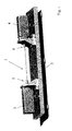
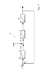
- a two-mass test bench 1 for condition monitoring of bearings is shown.
- the two-mass test rig 1 mounted on a carrier 2, has two synchronous machines 3 and 4.
- the bearings 5 and 6 are to be checked for damage in the context of condition monitoring according to the invention.
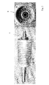
- the Fig. 2 shows the A-bearing 7 and the B-bearing 8 of the examined synchronous machines 3 and 4, which in the present case is the engine with the name DS 71 from Baumüller in Nuremberg.
- the stump or stub (encoder) is referred to with the A-bearing 7, while the B-bearing 8 represents the transducer side.
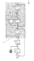
- the bearing damage diagnosis is carried out by means of a measurement in a closed speed control loop, the block diagram 9 in the Fig. 3 is shown.
- the block diagram 9 of Fig. 3 shows a closed speed control loop with mechanical dressing, as a dual mass oscillator in Circuit diagram is taken into account (cf. Fig. 1 ).
- the input of the closed speed control loop forms a predetermined speed setpoint or a setpoint angular speed ⁇ M * .
- a deviation from the nominal value, ⁇ M enters the controller parameterization as a control difference (proportional gain K P ), where T N denotes the controller parameter or the reset time.
- the pseudo-noise binary signal is added in addition to the output signal of the proportional integral speed controller (PI speed controller).
- i q * denotes the setpoint for the torque-forming component (iq) of the stator current.
- T si denotes a delay element with this time constant.
- the torque-forming component of the stator current i q is proportional to the drive torque m M , which is based on the nominal torque M N. Another time component comes through the ramp-up of the engine T M into play.
- ⁇ M denotes the motor angular velocity with reference to the nominal mechanical angular velocity ⁇ N.
- D denotes a normalized material damping of the spring; d thus represents a correction factor for the parameter fitting.
- the normalized spring constant is denoted by T C , T L indicates the acceleration time of the load.
- the spring moment is m F denotes the load torque with m L.
- the output forms the load angle velocity ⁇ L relative to the nominal mechanical angular velocity, ⁇ N.
- the system is excited by means of a pseudo-noise binary signal.
- the Welch method is preferably used according to the invention.
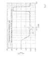
- the Fig. 4 shows an amplitude response 10 of a defect-free dual-mass oscillator and an amplitude response 11 of a dual-mass oscillator with damaged A-bearing of the prime mover.
- the amplitude responses 10, 11 the magnitude
- the input quantity û is 1A.
- the measurement refers to the A-bearing of a DS 71 engine, whereby a bearing was used as a defective bearing from the backware of a repair shop.
- the associated phase responses are in the Fig. 5 shown.
- the phase response 12 is the phase response at damaged bearing, the phase response 13 of the reference phase of the defect-free drive train.
- the deviation occurs in the phase response of the transfer function of the mechanical system G mech as expected in the range of the characteristic frequency of 12 Hz.
- the input quantity û is once again 1A.
- a targeted choice of the amplitude of the pseudo-noise binary signal an optimization of the traces can be achieved in such a way that bearing damage by a better expression of the deviations with regard to the respective reference curves are better to recognize.
- This better recognizability is also in the phase transition 20 of the defective dual mass oscillator compared to the phase response 21 of the defect-free dual mass oscillator, as in the Fig. 7 shown below.
- a deviation of the amplitude response 22 in the presence of a defect compared to the amplitude response 23 without defect can be seen.
- Fig. 9 the frequency response of a defect-free dual-mass oscillator and a dual-mass vibrator with damaged B-bearing of the prime mover is shown.
- f AR 10 Hz for the outer race.
- a significant deviation compared to the amplitude response 27 for the case of a defect-free bearing can be seen.
- a deviation always occurs between the currently measured frequency response of the damaged drive train and a reference frequency response as an indicator. The results are well reproducible.
- a frequency response is shown with a tolerance band around a reference curve.
- tolerance values or a tolerance band By specifying tolerance values or a tolerance band, automated error detection is possible.
- the tolerance bands 30 and 31 include the reference curve 32.
- a measured amplitude response 33 results, in which the tolerance range which is predetermined by the upper tolerance band 30 and the lower tolerance band 31 is left.
- a suitable algorithm searches in the range in particular for the characteristic error frequencies after such a deviation both in the amplitude and in the phase response. Accordingly, as in the Fig.
- an upper tolerance band 34 and a lower tolerance band 35 are also defined for the phase response.
- the two tolerance bands 34 and 35 surround the phase response of the defect-free system, which is designated here by the reference numeral 36. If a bearing damage is present, a phase transition 37 results, in which the region bounded by the tolerance bands 34 and 35 is clearly left here.
- a measurement configuration 38 for a measurement on a mechanically idling machine is shown.
- a setpoint value ⁇ * for the angular velocity is specified.
- K Pn denotes the proportional gain (controller parameter), T Nn the reset time or the corresponding controller parameter.
- PRBS pseudo-noise binary signal
- the torque setpoint is represented in the measurement configuration 38 as m i * .
- T s denotes a replacement time constant of the closed loop, T M again the ramp-up time of the motor.
- Output signal of the measurement configuration is the motor angular velocity ⁇ .
- s jw represents the complex angular frequency
- ⁇ M represents the motor angular velocity
- i q represents the torque-forming current component
- J M represents the moment of inertia of the motor.
- the phase is at the beginning at 0 ° and then goes to -90 °, since in a real system, no ideal integrator is given, but the system or the machine behaves in the range of very low frequencies as a VZ1-member, so as a Delay element of the first order.
- the Fig. 12 finally shows measurement results of a measurement on a mechanically idling machine, on the one hand, the amplitude response 39, on the other hand, the phase response 40 is shown.
- phase transition 40 three peaks can be seen which represent a deviation from the expected course and thus indicate a bearing damage as an indicator. These peaks are at the expected locations, namely at frequencies around 11 Hz and multiples thereof, namely 22 and 33 Hz.
- the measurement on an idling machine allows the measurement in the test field or repair shop to investigate whether bearing damage is present , Disassembly of the machine is not required.
Landscapes
- Physics & Mathematics (AREA)
- General Physics & Mathematics (AREA)
- Testing Of Devices, Machine Parts, Or Other Structures Thereof (AREA)
Priority Applications (1)
| Application Number | Priority Date | Filing Date | Title |
|---|---|---|---|
| EP09158627A EP2244080A1 (fr) | 2009-04-23 | 2009-04-23 | Procédé de surveillance d'état de stockages remplissant des fonctions précises de machines synchrones excitées en permanence et dispositif correspondant destiné à la surveillance d'état |
Applications Claiming Priority (1)
| Application Number | Priority Date | Filing Date | Title |
|---|---|---|---|
| EP09158627A EP2244080A1 (fr) | 2009-04-23 | 2009-04-23 | Procédé de surveillance d'état de stockages remplissant des fonctions précises de machines synchrones excitées en permanence et dispositif correspondant destiné à la surveillance d'état |
Publications (1)
| Publication Number | Publication Date |
|---|---|
| EP2244080A1 true EP2244080A1 (fr) | 2010-10-27 |
Family
ID=40934852
Family Applications (1)
| Application Number | Title | Priority Date | Filing Date |
|---|---|---|---|
| EP09158627A Withdrawn EP2244080A1 (fr) | 2009-04-23 | 2009-04-23 | Procédé de surveillance d'état de stockages remplissant des fonctions précises de machines synchrones excitées en permanence et dispositif correspondant destiné à la surveillance d'état |
Country Status (1)
| Country | Link |
|---|---|
| EP (1) | EP2244080A1 (fr) |
Cited By (9)
| Publication number | Priority date | Publication date | Assignee | Title |
|---|---|---|---|---|
| WO2011104084A1 (fr) * | 2010-02-24 | 2011-09-01 | Siemens Aktiengesellschaft | Procédé d'évaluation de décharges en arc et banc d'essai associé |
| AT517886A1 (de) * | 2015-11-05 | 2017-05-15 | Engel Austria Gmbh | Vorrichtung zum Überprüfen eines Zustandes eines Maschinenteils |
| DE102016222660A1 (de) * | 2016-11-17 | 2018-05-17 | Volkswagen Aktiengesellschaft | Verfahren und Vorrichtung zum Erkennen von Veränderungen in einem elektrisch betriebenen Antrieb |
| CN108152034A (zh) * | 2017-12-22 | 2018-06-12 | 镇江市高等专科学校 | 永磁耦合传动设备运行状态监测装置及监测方法 |
| EP3617724A1 (fr) | 2018-08-31 | 2020-03-04 | Siemens Aktiengesellschaft | Surveillance d'une machine électrique |
| CN113295412A (zh) * | 2021-05-26 | 2021-08-24 | 华能澜沧江水电股份有限公司 | 一种检测立式水轮发电机组导轴承受力不平衡原因的方法 |
| WO2023020698A1 (fr) | 2021-08-19 | 2023-02-23 | Siemens Aktiengesellschaft | Procédé et dispositif de surveillance de machine électrique |
| CN116337451A (zh) * | 2023-05-29 | 2023-06-27 | 山东金帝精密机械科技股份有限公司 | 一种椭圆形轴承保持器静音优化方法、设备及介质 |
| CN121784542A (zh) * | 2026-03-06 | 2026-04-03 | 山东奥卓电气科技发展有限公司 | 一种永磁同步驱动器的运行安全监管系统及方法 |
Citations (2)
| Publication number | Priority date | Publication date | Assignee | Title |
|---|---|---|---|---|
| US6053047A (en) * | 1998-09-29 | 2000-04-25 | Allen-Bradley Company, Llc | Determining faults in multiple bearings using one vibration sensor |
| DE102004050897A1 (de) * | 2004-10-19 | 2006-05-11 | Siemens Ag | Verfahren und Einrichtung zur Erkennung eines schadhaften Lagers einer rotierend umlaufenden Welle |
-
2009
- 2009-04-23 EP EP09158627A patent/EP2244080A1/fr not_active Withdrawn
Patent Citations (2)
| Publication number | Priority date | Publication date | Assignee | Title |
|---|---|---|---|---|
| US6053047A (en) * | 1998-09-29 | 2000-04-25 | Allen-Bradley Company, Llc | Determining faults in multiple bearings using one vibration sensor |
| DE102004050897A1 (de) * | 2004-10-19 | 2006-05-11 | Siemens Ag | Verfahren und Einrichtung zur Erkennung eines schadhaften Lagers einer rotierend umlaufenden Welle |
Non-Patent Citations (4)
| Title |
|---|
| "Messung der Übertragungsfunktion zur Optimierung der Wälzlagerdiagnose", AACHENER KOLLOQUIUM FÜR INSTANDHALTUNG, DIAGNOSE UND ANLAGENÜBERWACHUNG, vol. 46, no. 6, 7 November 2002 (2002-11-07), pages 591 - 606 |
| J. R. STACK; T. G. HABETLER; R. G. HARLEY: "Bearing fault detection via autoregressive stator current modeling", IEEE TRANSACTIONS ON INDUSTRY APPLICATIONS, vol. 40, no. 3, May 2004 (2004-05-01) |
| O. V. THORSEN; M. DALVA, METHODS OF CONDITION MONITORING AND FAULT DIAGNOSIS FOR INDUCTION MOTORS, vol. 8, no. 5, September 1998 (1998-09-01) |
| VILLWOCK, SEBASTIAN: "Identifikationsmethoden für die automatisierte Inbetriebnahme und Zustandsüberwachung elektrischer Antriebe", 2007, UNIVERSITÄTSBIBLIOTHEK SIEGEN, XP002542553 * |
Cited By (15)
| Publication number | Priority date | Publication date | Assignee | Title |
|---|---|---|---|---|
| WO2011104084A1 (fr) * | 2010-02-24 | 2011-09-01 | Siemens Aktiengesellschaft | Procédé d'évaluation de décharges en arc et banc d'essai associé |
| US9046579B2 (en) | 2010-02-24 | 2015-06-02 | Siemens Aktiengesellschaft | Electric arc discharge evaluation method, and associated test stand |
| US10203677B2 (en) | 2015-11-05 | 2019-02-12 | Engel Austria Gmbh | Apparatus for checking a state of a machine part |
| AT517886B1 (de) * | 2015-11-05 | 2018-05-15 | Engel Austria Gmbh | Vorrichtung zum Überprüfen eines Zustandes eines Maschinenteils |
| AT517886A1 (de) * | 2015-11-05 | 2017-05-15 | Engel Austria Gmbh | Vorrichtung zum Überprüfen eines Zustandes eines Maschinenteils |
| DE102016222660A1 (de) * | 2016-11-17 | 2018-05-17 | Volkswagen Aktiengesellschaft | Verfahren und Vorrichtung zum Erkennen von Veränderungen in einem elektrisch betriebenen Antrieb |
| CN108152034A (zh) * | 2017-12-22 | 2018-06-12 | 镇江市高等专科学校 | 永磁耦合传动设备运行状态监测装置及监测方法 |
| CN108152034B (zh) * | 2017-12-22 | 2023-11-10 | 江苏磁谷科技股份有限公司 | 永磁耦合传动设备运行状态监测装置及监测方法 |
| EP3617724A1 (fr) | 2018-08-31 | 2020-03-04 | Siemens Aktiengesellschaft | Surveillance d'une machine électrique |
| CN113295412A (zh) * | 2021-05-26 | 2021-08-24 | 华能澜沧江水电股份有限公司 | 一种检测立式水轮发电机组导轴承受力不平衡原因的方法 |
| CN113295412B (zh) * | 2021-05-26 | 2022-10-11 | 华能澜沧江水电股份有限公司 | 一种检测立式水轮发电机组导轴承受力不平衡原因的方法 |
| WO2023020698A1 (fr) | 2021-08-19 | 2023-02-23 | Siemens Aktiengesellschaft | Procédé et dispositif de surveillance de machine électrique |
| CN116337451A (zh) * | 2023-05-29 | 2023-06-27 | 山东金帝精密机械科技股份有限公司 | 一种椭圆形轴承保持器静音优化方法、设备及介质 |
| CN116337451B (zh) * | 2023-05-29 | 2023-08-22 | 山东金帝精密机械科技股份有限公司 | 一种椭圆形轴承保持器静音优化方法、设备及介质 |
| CN121784542A (zh) * | 2026-03-06 | 2026-04-03 | 山东奥卓电气科技发展有限公司 | 一种永磁同步驱动器的运行安全监管系统及方法 |
Similar Documents
| Publication | Publication Date | Title |
|---|---|---|
| DE69732569T2 (de) | System zur erkennung von störungen von elektromotoren | |
| EP2340608B1 (fr) | Procédé et dispositif de surveillance et/ou d'analyse de rotors de machines électriques en fonctionnement | |
| DE69327066T2 (de) | Verfahren und Anordnung zum Feststellen von Statorfehlern in rotierenden dynamoelektrischen Maschinen | |
| EP2539679B1 (fr) | Système ou procédé de détermination de l'état d'un palier | |
| DE102008025596B4 (de) | Verfahren zum Betrieb einer Einrichtung | |
| EP2421145B1 (fr) | Dispositif et procédé d'identification des paramètres d'un schéma électrique équivalent d'un moteur asynchrone triphasé sans utilisation d'encodeur de vitesse | |
| EP2549257B1 (fr) | Procédé de détection de dommages sur des engrenages | |
| DE102009038011B9 (de) | Verfahren zur automatischen Erfassung und Erkennung von Fehlern an einer Auswuchtmaschine | |
| DE19917541B4 (de) | Verfahren zur Fehlerdiagnose | |
| Zoubek et al. | Frequency response analysis for rolling-bearing damage diagnosis | |
| DE112019007189T5 (de) | Anomaliediagnosevorrichtung für Elektromotorausrüstungen, Anomaliediagnoseverfahren für Elektromotorausrüstungen und Anomaliediagnosesystem für Elektromotorausrüstungen | |
| EP2549245A1 (fr) | Procédé et dispositif de surveillance d'oscillations de la tête de bobine d'un générateur | |
| DE102016222660A1 (de) | Verfahren und Vorrichtung zum Erkennen von Veränderungen in einem elektrisch betriebenen Antrieb | |
| DE102010053098A1 (de) | Verfahren zur Überwachung eines Rotorlagegebers | |
| EP2757384A2 (fr) | Procédé et dispositif de détection de fautes dans une machine électrique | |
| EP3726234A1 (fr) | Procédé de diagnostic d'un moteur électrique | |
| EP2990609A1 (fr) | Procédé de fonctionnement d'une installation de machine dotée d'une ligne d'arbres | |
| EP2942633A1 (fr) | Procédé et dispositif de détection de court-circuit entre spires et machine électrique | |
| WO2023020698A1 (fr) | Procédé et dispositif de surveillance de machine électrique | |
| DE102015210911A1 (de) | Verfahren und Vorrichtung zum Erkennen von Veränderungen in einem elektrisch betriebenen Antrieb | |
| DE102019207545B3 (de) | Verfahren zum Ermitteln eines Fehlers einer elektrischen Maschine und elektrische Maschine | |
| König et al. | Getriebespezifische Schadensanalyse an elektromechanischen Antriebssystemen unter Verwendung mehrerer Beschleunigungs-sensoren und künstlich neuronaler Netze Gearbox-specific failure analysis on electromechanical drive systems using multiple acceleration sensors and artificial neural networks | |
| EP2273249A1 (fr) | Procédé et dispositif pour la détection de dommages des paliers sans capteur et pour l'identification de système d'un entraînement électrique | |
| EP4173122B1 (fr) | Procédé pour surveiller le fonctionnement d'un composant d'entraînement, dispositif et utilisation | |
| EP0961130B1 (fr) | Procédé et appareil pour la détection précoce de défauts de rotor dans une machine asynchrone |
Legal Events
| Date | Code | Title | Description |
|---|---|---|---|
| PUAI | Public reference made under article 153(3) epc to a published international application that has entered the european phase |
Free format text: ORIGINAL CODE: 0009012 |
|
| AK | Designated contracting states |
Kind code of ref document: A1 Designated state(s): AT BE BG CH CY CZ DE DK EE ES FI FR GB GR HR HU IE IS IT LI LT LU LV MC MK MT NL NO PL PT RO SE SI SK TR |
|
| STAA | Information on the status of an ep patent application or granted ep patent |
Free format text: STATUS: THE APPLICATION IS DEEMED TO BE WITHDRAWN |
|
| 18D | Application deemed to be withdrawn |
Effective date: 20110428 |