EP2244176A1 - Procédé de commande d'un dispositif d'affichage à l'aide d'un dispositif de commande dans un système informatique et produit de programme informatique - Google Patents
Procédé de commande d'un dispositif d'affichage à l'aide d'un dispositif de commande dans un système informatique et produit de programme informatique Download PDFInfo
- Publication number
- EP2244176A1 EP2244176A1 EP09010001A EP09010001A EP2244176A1 EP 2244176 A1 EP2244176 A1 EP 2244176A1 EP 09010001 A EP09010001 A EP 09010001A EP 09010001 A EP09010001 A EP 09010001A EP 2244176 A1 EP2244176 A1 EP 2244176A1
- Authority
- EP
- European Patent Office
- Prior art keywords
- graphic
- volatile
- display
- graphic element
- graphical
- Prior art date
- Legal status (The legal status is an assumption and is not a legal conclusion. Google has not performed a legal analysis and makes no representation as to the accuracy of the status listed.)
- Withdrawn
Links
Images



Classifications
-
- G—PHYSICS
- G06—COMPUTING OR CALCULATING; COUNTING
- G06F—ELECTRIC DIGITAL DATA PROCESSING
- G06F3/00—Input arrangements for transferring data to be processed into a form capable of being handled by the computer; Output arrangements for transferring data from processing unit to output unit, e.g. interface arrangements
- G06F3/01—Input arrangements or combined input and output arrangements for interaction between user and computer
- G06F3/048—Interaction techniques based on graphical user interfaces [GUI]
- G06F3/0481—Interaction techniques based on graphical user interfaces [GUI] based on specific properties of the displayed interaction object or a metaphor-based environment, e.g. interaction with desktop elements like windows or icons, or assisted by a cursor's changing behaviour or appearance
-
- G—PHYSICS
- G06—COMPUTING OR CALCULATING; COUNTING
- G06F—ELECTRIC DIGITAL DATA PROCESSING
- G06F3/00—Input arrangements for transferring data to be processed into a form capable of being handled by the computer; Output arrangements for transferring data from processing unit to output unit, e.g. interface arrangements
- G06F3/01—Input arrangements or combined input and output arrangements for interaction between user and computer
- G06F3/048—Interaction techniques based on graphical user interfaces [GUI]
- G06F3/0484—Interaction techniques based on graphical user interfaces [GUI] for the control of specific functions or operations, e.g. selecting or manipulating an object, an image or a displayed text element, setting a parameter value or selecting a range
- G06F3/0486—Drag-and-drop
Definitions
- the invention relates to a method for controlling a display device by means of a control device in a computer system as well as a computer program product.
- PC personal computer
- Executable objects such as programs, data collections or multimedia files are mixed with a multitude of other files required for the execution, so that the user has no user interface for productive PC use.
- Application programs organize their files, such as e-mails, documents, photos or multimedia files, in specially designed collections of data, which the user mentally assigns to a specific application program according to the function and file type to be called, and then to the program and its specific user interface must start.
- This distribution of data storage makes PC operation impractical and unproductive with the increasing proliferation of data and application programs.
- the proliferation of application programs and data storage results in a deterioration of the usability of the entire system due to the multiplication of data storage and workflow structures to use the entire functionality of the PC.
- one or more graphic elements be displayed in a volatile manner, which means that they only appear on the display surface if previously positioned by means of the control device of the computer system a positioning of a graphical marking, for example Cursor of the mouse device was detected in a certain area of the display area.
- a graphical marking for example Cursor of the mouse device was detected in a certain area of the display area.
- Such volatile rendering of graphical elements is known, for example, in conjunction with so-called pull-down menus.
- Such graphical elements are thus not permanently part of the graphical interface on the display device.
- graphical interface elements that are substantially permanently displayed on the display surface when the computer system is started, deleted, or recreated.
- such graphical interface elements also "disappear" from the display area when, for example, they are obscured by a launched software application. However, they are displayed on the display area when the user has a kind of default used by the computer system, which can be characterized in particular by the fact that no software applications are started.
- the object of the invention is to provide an improved method for controlling a display device by means of a control device in a computer system that enables an optimized and user-friendly utilization of a display surface of the display device of the computer system.
- an optimal surface utilization of the display surface is achieved in conjunction with edge-side arranged graphic surface elements.
- the representation of the one or more graphical interface elements may be on any side of the edge of the display area.
- the representation of a symbol structure formed by volatile graphic elements then takes place in the proposed method, preferably in a direction away from the edge of the display surface.
- the graphical interface itself is preferably part of a basic surface display of the computer system, the fugitive graphics are displayed on the display surface only if a certain positioning on the display surface is detected for the graphical highlight, for example a cursor of a mouse device, namely one the graphic surface elements, which in turn are arranged at the edge. Detecting the positioning of the graphical highlight relative to the graphical user interface means that the graphical highlight is either detected adjacent to the graphical user interface or even at least partially overlapped with the display of the graphical user interface on the display surface.
- the volatile graphic elements are each linked by means of the control device of the computer system with a software object, which may be any object in the context of the applications running on the computer system. For example, it may be a directory of one or more files, for example an image file or a digital language file. It can also be at the object to a act executable software application.
- the linking of the volatile graphic element with the software object means that a mutual assignment takes place here.
- the user may access the software object, for example, display an image, initiate a data output or start another software application.
- the first volatile graphic element and a mapping element graphically associated with the graphical user interface element and the first fugitive graphic element are displayed on the display surface.
- This can be a direct graphical association between the graphical interface element and the first volatile graphic element, which can be represented on the display surface, for example, by means of a line connecting the two elements.
- the first fugitive graphic element is graphically associated with the graphical interface element via another fugitive graphic element, by means of line elements between the graphical interface element and the other fugitive graphic element and between the other fugitive graphic element and the first fugitive graphic element on the display surface can be represented.
- the other volatile graphic element is then displayed together with the first volatile graphic element.
- mother-child relationships namely between the graphic surfel and the other fugitive graphic element and between the other fugitive graphic element and the first fugitive graphic element.
- addition symbols are graphically displayed in one or more free display areas adjacent to the first fugitive graphic element, for example in the form of a plus sign. This indicates to the user that in this display area, a new fugitive graphic element may be placed by the user to augment the symbol structure of fugitive graphic elements associated with the graphical UI element.
- Checking for free display areas prevents conflict with existing, volatile graphics and therefore controls the display in conflict-free and user friendly way. In display areas adjacent to the first volatile graphic element classified as not free, no addition symbol is displayed.
- a preferred embodiment of the invention provides that, when checking for free display areas, a display area is classified as not free if a third volatile graphic element is displayed in the display area, which links to a software object and which is likewise assigned to the graphic interface element.
- the classification as non-free display area then has the result that no graphical addition symbol is displayed there.
- the software object associated with the third volatile graphic element can be the same or a different software object than the software object associated with the first and / or the second volatile graphic element.
- the first volatile graphic element is comprehensively represented by a plurality of volatile graphic sub-elements which are each linked to a software object.
- two, three or four software objects may be associated with a fugitive graphics element, which then results in a corresponding number of fugitive graphics sub-elements or symbols in the region of the fugitive graphic element.
- a further development of the invention further comprises the following steps: detecting a positioning of the graphic marking on the display surface in relation to one of the addition symbols by means of the control device, representing a new volatile graphic element in the display area of the one add symbol, and a first assignable graphic element and the new volatile graphic element graphically assigning assignment element on the display surface and linking the new volatile graphic element with a software object according to a previously selected by the control device user selection.
- the controller After displaying one or more addition symbols on the display area adjacent to the first volatile graphic element, it is detected by the controller that the user has displaced the graphic mark in the area of one of the addition symbols, for example, in a display area area adjacent to, or even adjacent to, the addition symbol overlapping, in this area of the display area, the addition symbol is replaced by a new volatile graphic element.
- the new volatile graphic element is graphically associated with the first fugitive graphic element, for example by means of a stroke between the graphic elements.
- the newly created volatile graphic element is then linked to a software object which corresponds to a user selection previously detected by the control device.
- This selection by the user takes place in one exemplary embodiment in that the user selects a graphical element displayed on the display surface by means of a so-called drag-drop function and moves it into the area of the addition symbol.
- the selection of one or more software objects associated with this graphic element is then completely or partially adopted for the new volatile graphic element.
- the acquired software object (s) and the new volatile graphic element are then integrated into the symbol structure of fugitive graphic elements for the graphic UI element.
- a volatile graphic element is removed again by means of user selection from such a structure, which can also be implemented, for example, by means of the drag-drop function.
- Fig. 1 shows a schematic representation of a computer system with an executed as a screen display device 1, on which a display surface 2 for displaying information is available. Connected to the display device 1 with a keyboard 2, which serves for detecting user input.
- the display device 1 is connected to a control device 4, which is formed in the illustrated embodiment in a separate housing.
- the control device 4 usually comprises at least one processor device as well as a memory device and suitable interfaces for data exchange with peripheral devices, to which the display device 1 and the keyboard 3 belong.
- Fig. 1 not shown is an optional mouse device.
- the computer system may be implemented as a so-called personal computer.
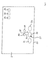
- FIG. 2 to 8 exemplary embodiments of a method for controlling the display device 1 by means of the control device 4 in the computer system will follow Fig. 1 described.
- the Fig. 2 to 8 show different representations on the display surface 2 of the display device. 1
- a plurality of graphical surface elements 21, 22, 23 are shown on the display surface 2 adjacent to a lower edge 20 .
- graphical interface elements 24, 24, 26 are shown on the display surface 2 .
- the graphical user interface elements 21,..., 26 are each assigned one or more software objects that can be accessed by the user by selecting the respective graphical interface element, for example by a graphical marking 27, a mouse device and / or the keyboard 3 of the computer system is assigned in the area of the graphical user interface element and a user input is made.
- a software application can be started on the computer system in this way.
- a symbol structure 28 having a first and a second volatile graphic element 29, 30 is illustrated for the mean surface graphical element 22. Connected are the graphical interface element 22 and the first and second fugitive graphics elements 29, 30 via graphical mapping elements 31, 32.
- the "unfolding" or displaying the symbol structure 28 always takes place in a direction away from the edge 20 of the display surface 2, preferably in a direction perpendicular to the edge 20th
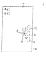
- Fig. 3 shows a representation in which now the graphic mark 27 has been moved in the area of the first volatile graphic element 29.
- the control device 4 has thereupon checked on which sides of the first volatile graphic element 29 there are still free display areas, so that new volatile graphic elements could be displayed there.
- Fig. 3 is shown schematically by means of a graphic symbol 24 'that the user has previously selected the further graphical interface element 24 by means of drag-drop function.
- Fig. 4 For example, the user can then select one of the display areas corresponding to the two addition symbols 33, 34 by means of the graphic marking 27 by shifting the graphic marking 27 there. Detects the control device 4 such a shift according to the in Fig. 4
- a new fugitive graphic element 35 is shown on the display surface 2 which is connected to the first fugitive graphic element by means of a new graphic mapping element 36.
- the symbol structure associated with the central graphical interface element 22 has been supplemented with fugitive or concealed graphic elements.
- Fig. 6 shows an embodiment in which addition symbols 33, 34 are shown, indicating the user free display area for adding more volatile graphic elements.
- the control device 4 has determined this embodiment after detecting the graphic mark 27 in checking free display areas that in a region 60 below a user-selected, volatile graphic element 61 no free display area exists. Rather, the area 60 is already occupied, which is why the addition symbols 33, 34 are displayed only above and on the right side of the user-selected, volatile graphic element 61. According to Fig. 7 Then, a user selection for the area above the user-selected, volatile graphic element 61 was detected and another new, volatile graphic element 70 is displayed.
- the volatile graphic elements may comprise a plurality of volatile graphic sub-elements, each of which is linked to a software object. So shows Fig. 8 a volatile graphic symbol 80 with two volatile graphic part symbols 81, 82. Furthermore, a volatile graphic element 83 is shown, which comprises four volatile graphic sub-elements 84, ..., 87.
- the control of the symbol structure with volatile graphic elements controlled by the control device 4 corresponds to a type of domino principle in which an extension of the symbol structure is provided to the user on pairs opposite sides, if the respective page is still occupied by a free display area.
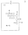
- FIG. 3 shows a schematic illustration with an arrangement of volatile graphic elements 90.
- the arrangement of the graphic elements 90 is based on the graphic surface element 23, which forms a kind of base element. Deviating from the illustration in Fig. 9 can be formed on the base member 23 and other tree structures, which in turn are then carried out again after the domino part.
- the base element can be chosen in any form as an object, area or body.
- On the base element is a central trunk, from which then branches can be formed in any way.
- the graphic elements can be any files present in the file system.
- the program functionalities are called from the graphic elements just as the operating system, as is known as such for so-called desktop icons.
- the user can form the arrangement of the graphic elements, for example by means of "drag & drop", as described above.
- the structure shown makes it possible to arrange program groups spatially, to arrange unfinished files on a page, to form a series of documents or e-books to be edited, to display the upcoming appointments from calendar elements.
- the method is also suitable for all programs that build up sequential or decision chaining, for example diagnosis, accident, analysis, learning programs or the like.
- logical sequences of structures in the retrieval of files are created by means of a mouse mouse guided by an animation, and, for example, task files to be performed successively can be arranged in a juxtaposed structure. Due to the spatial arrangement in horizontal and vertical direction, each user can adapt to his working and thinking habits Create a universal operating and working interface whose operation and structure does not depend on the type of data and the programs that created it.
- the domino-like tree structure is also suitable for the program interface of individual application programs in that the user can arrange his own program surface from the individual program functions.
Landscapes
- Engineering & Computer Science (AREA)
- General Engineering & Computer Science (AREA)
- Theoretical Computer Science (AREA)
- Human Computer Interaction (AREA)
- Physics & Mathematics (AREA)
- General Physics & Mathematics (AREA)
- User Interface Of Digital Computer (AREA)
Priority Applications (1)
| Application Number | Priority Date | Filing Date | Title |
|---|---|---|---|
| EP09010001A EP2244176A1 (fr) | 2009-04-03 | 2009-08-03 | Procédé de commande d'un dispositif d'affichage à l'aide d'un dispositif de commande dans un système informatique et produit de programme informatique |
Applications Claiming Priority (3)
| Application Number | Priority Date | Filing Date | Title |
|---|---|---|---|
| EP09004964 | 2009-04-03 | ||
| DE200910017078 DE102009017078A1 (de) | 2009-04-08 | 2009-04-08 | Vorrichtung zur Darstellung von Daten und Programmen als Icons auf einer computergestützen Benutzeroberfläche |
| EP09010001A EP2244176A1 (fr) | 2009-04-03 | 2009-08-03 | Procédé de commande d'un dispositif d'affichage à l'aide d'un dispositif de commande dans un système informatique et produit de programme informatique |
Publications (1)
| Publication Number | Publication Date |
|---|---|
| EP2244176A1 true EP2244176A1 (fr) | 2010-10-27 |
Family
ID=41263651
Family Applications (1)
| Application Number | Title | Priority Date | Filing Date |
|---|---|---|---|
| EP09010001A Withdrawn EP2244176A1 (fr) | 2009-04-03 | 2009-08-03 | Procédé de commande d'un dispositif d'affichage à l'aide d'un dispositif de commande dans un système informatique et produit de programme informatique |
Country Status (1)
| Country | Link |
|---|---|
| EP (1) | EP2244176A1 (fr) |
Citations (1)
| Publication number | Priority date | Publication date | Assignee | Title |
|---|---|---|---|---|
| US20070234237A1 (en) * | 2006-03-31 | 2007-10-04 | Microsoft Corporation | Two dimensional trees to edit graph-like diagrams |
-
2009
- 2009-08-03 EP EP09010001A patent/EP2244176A1/fr not_active Withdrawn
Patent Citations (1)
| Publication number | Priority date | Publication date | Assignee | Title |
|---|---|---|---|---|
| US20070234237A1 (en) * | 2006-03-31 | 2007-10-04 | Microsoft Corporation | Two dimensional trees to edit graph-like diagrams |
Similar Documents
| Publication | Publication Date | Title |
|---|---|---|
| DE69732547T2 (de) | Verfahren und Gerät zum Zusammenklappen und zur Ausdehnung auserwählter Bereiche von Arbeitsräumen auf einem von einem Rechner kontrollierten Anzeigesystem | |
| DE69428988T2 (de) | Interaktive anwenderschnittstelle | |
| DE60003246T2 (de) | Software Schnittstelle | |
| DE69331025T2 (de) | System und Verfahren für Rechnerschnittstellen | |
| DE69526545T2 (de) | Ein Verfahren und Gerät zur Darstellung von Datenbanksuchergebnissen | |
| DE69130773T2 (de) | Elektronische anzeige und datenverarbeitungsvorrichtung | |
| DE69622827T2 (de) | Verfahren und Gerät zur Verbesserung der Navigation eines Online-Informationsdienstes mit mehreren Betriebsmitteln | |
| DE4301766C2 (de) | Verfahren zum Darstellen eines doppelseitigen, umwendbaren elektronischen Papiers | |
| DE69808780T2 (de) | Browser für hierarchische strukturen | |
| DE69817168T2 (de) | Interaktive zeitspannenanzeige | |
| DE69718721T2 (de) | Verfahren und Vorrichtung zum Organisieren und zur Anzeige von langen Datenlisten in einem Arbeitsraum eines Rechneranzeigesystems | |
| DE69232110T2 (de) | Darstellungssystem von Geschichtsinhalt für einen Informationsprozessor | |
| DE69618067T2 (de) | Intelligente Auswahl von graphischen Objekten, markanten Punkten und Beziehungen | |
| CH703723A1 (de) | Verfahren zur konfiguration einer grafischen benutzerschnittstelle. | |
| DE112010006077T5 (de) | Bildschirmerzeugungssystem für programmierbare Anzeige | |
| CH703724A1 (de) | Grafische benutzerschnittstelle. | |
| DE69605247T2 (de) | Methode und Editiersystem zur Stellung einer Werkzeugtaste | |
| DE102023122773A1 (de) | Bindung von daten an grafische objekte vermittels eines visuellen indikators | |
| EP1701258A1 (fr) | Représentation de structures logicielles hiérarchiques | |
| DE69808152T2 (de) | Darstellung logisch veknüpfter daten | |
| DE102008008730B4 (de) | Vorrichtung und Verfahren zur Animation eines grafischen digitalen Dokumentes | |
| EP3087464B1 (fr) | Dispositif de navigation et procédé pour représenter un arbre de navigation au niveau d'un dispositif d'affichage | |
| EP1714206A1 (fr) | Visualisation de donnees structurees | |
| EP2842023B1 (fr) | Procédé et dispositif de visualisation d'un ensemble de données pouvant être trié de manière hiérarchique, en particulier dans un véhicule | |
| EP0986790B1 (fr) | Procede de representation de plus nombreuses donnees renfermant des elements graphiques et de navigation dans de telles donnees |
Legal Events
| Date | Code | Title | Description |
|---|---|---|---|
| PUAI | Public reference made under article 153(3) epc to a published international application that has entered the european phase |
Free format text: ORIGINAL CODE: 0009012 |
|
| 17P | Request for examination filed |
Effective date: 20100607 |
|
| AK | Designated contracting states |
Kind code of ref document: A1 Designated state(s): AT BE BG CH CY CZ DE DK EE ES FI FR GB GR HR HU IE IS IT LI LT LU LV MC MK MT NL NO PL PT RO SE SI SK SM TR |
|
| AX | Request for extension of the european patent |
Extension state: AL BA RS |
|
| RAP1 | Party data changed (applicant data changed or rights of an application transferred) |
Owner name: RA-MICRO GMBH & CO. KG |
|
| RAP1 | Party data changed (applicant data changed or rights of an application transferred) |
Owner name: DRB VERWALTUNGSGESELLSCHAFT GMBH & CO. KG |
|
| 17Q | First examination report despatched |
Effective date: 20130419 |
|
| STAA | Information on the status of an ep patent application or granted ep patent |
Free format text: STATUS: THE APPLICATION HAS BEEN WITHDRAWN |
|
| 18W | Application withdrawn |
Effective date: 20130808 |