EP2244249A1 - Antenne électro-acoustique sous-marine - Google Patents
Antenne électro-acoustique sous-marine Download PDFInfo
- Publication number
- EP2244249A1 EP2244249A1 EP10157817A EP10157817A EP2244249A1 EP 2244249 A1 EP2244249 A1 EP 2244249A1 EP 10157817 A EP10157817 A EP 10157817A EP 10157817 A EP10157817 A EP 10157817A EP 2244249 A1 EP2244249 A1 EP 2244249A1
- Authority
- EP
- European Patent Office
- Prior art keywords
- reflector
- rocker
- antenna according
- cam portion
- underwater antenna
- Prior art date
- Legal status (The legal status is an assumption and is not a legal conclusion. Google has not performed a legal analysis and makes no representation as to the accuracy of the status listed.)
- Granted
Links
Images


Classifications
-
- H—ELECTRICITY
- H01—ELECTRIC ELEMENTS
- H01Q—ANTENNAS, i.e. RADIO AERIALS
- H01Q1/00—Details of, or arrangements associated with, antennas
- H01Q1/04—Adaptation for subterranean or subaqueous use
-
- G—PHYSICS
- G10—MUSICAL INSTRUMENTS; ACOUSTICS
- G10K—SOUND-PRODUCING DEVICES; METHODS OR DEVICES FOR PROTECTING AGAINST, OR FOR DAMPING, NOISE OR OTHER ACOUSTIC WAVES IN GENERAL; ACOUSTICS NOT OTHERWISE PROVIDED FOR
- G10K11/00—Methods or devices for transmitting, conducting or directing sound in general; Methods or devices for protecting against, or for damping, noise or other acoustic waves in general
- G10K11/004—Mounting transducers, e.g. provided with mechanical moving or orienting device
- G10K11/006—Transducer mounting in underwater equipment, e.g. sonobuoys
-
- B—PERFORMING OPERATIONS; TRANSPORTING
- B63—SHIPS OR OTHER WATERBORNE VESSELS; RELATED EQUIPMENT
- B63G—OFFENSIVE OR DEFENSIVE ARRANGEMENTS ON VESSELS; MINE-LAYING; MINE-SWEEPING; SUBMARINES; AIRCRAFT CARRIERS
- B63G8/00—Underwater vessels, e.g. submarines; Equipment specially adapted therefor
- B63G8/39—Arrangements of sonic watch equipment, e.g. low-frequency, sonar
-
- H—ELECTRICITY
- H01—ELECTRIC ELEMENTS
- H01Q—ANTENNAS, i.e. RADIO AERIALS
- H01Q1/00—Details of, or arrangements associated with, antennas
- H01Q1/12—Supports; Mounting means
- H01Q1/1207—Supports; Mounting means for fastening a rigid aerial element
-
- H—ELECTRICITY
- H01—ELECTRIC ELEMENTS
- H01Q—ANTENNAS, i.e. RADIO AERIALS
- H01Q15/00—Devices for reflection, refraction, diffraction or polarisation of waves radiated from an antenna, e.g. quasi-optical devices
- H01Q15/14—Reflecting surfaces; Equivalent structures
Definitions
- the invention relates to an electroacoustic underwater antenna according to the preamble of claim 1.
- flank array, known, linear underwater antenna ( DE 38 34 669 A1 ) has arranged at a distance from the hull body transducer assembly with a plurality of in the mounting position of the underwater antenna along the hull horizontally lined up, spaced apart hydrophones and the shielding effect against the hull radiated sound in a sound incidence behind the hydrophones arranged insulation board on the spring Mass principle is designed and acts as a low-noise reflector in the lower frequency range.
- the hydrophones are held on the insulation board via a clamp construction, and the insulation board is fixed with resilient elements to a bending wave absorbing damping layer which is connected to the hull.
- the transducer assembly is mechanically protected by an enveloping body attached to the hull. Due to a streamlined structure, the enveloping body offers protection against flow noise at the same time.
- the acoustic wave impedance of the envelope is approximately equal to that of the surrounding water, whereby the acoustic transmission loss and the reflection factor of the envelope for incident sound waves is low. If the enveloping body constructed as a layer composite, as this from the DE 36 42 747 C2 is known, also the radiation of noise, which is caused by bending waves due to structure-borne noise and turbulence, avoided by the enveloping body on the transducer assembly.
- the invention has for its object to design a cost-effective underwater antenna with only a few individual components in particular for attachment to the hull of a submarine, in which the reflector carrying the electronic transducer assembly a sufficiently large distance from the antenna carrier, So from the hull, has, from this acoustically well decoupled and is largely resistant to shock load.
- the electroacoustic underwater antenna according to the invention has the advantage that a large distance of the reflector and a good acoustic decoupling of the reflector from the antenna carrier is achieved by the two wings, each extending over the entire length of the reflector.
- the required spring constant of the wings can be easily adjusted by shape and material thickness.
- the impact energy of striking the reflector shock waves is transmitted over the wings distributed over the antenna carrier on the surface, whereby the antenna structure is shock resistant. Due to the different shapes of the two wings can be achieved with sufficient shock resistance of the antenna structure vertical alignment of the reflector on the hull of a submarine.
- the rockers are arranged so that the U-openings in the two wings point away from each other.
- the intermediate space between the upper and lower rocker is filled by a buoyant body which extends on the one hand to the antenna support and on the other hand ends at a distance in front of the reflector.
- the buoyancy body which preferably consists of a rigid foam core enclosed by a potting compound, the underwater antenna is kept substantially neutral in weight under water.
- the Buoyancy body through the connection of the Buoyancy body to the rear part of the two wings made a certain stiffening between the wings and thus their spring property can be influenced.
- an elastic layer which preferably consists of rubber cork
- each lug one of the rear bearing limbs is frictionally screwed on the antenna carrier tightening bolts.
- Between the bolt heads of the bolts and the plant legs existing transverse power disks are arranged made of fiberglass reinforced plastic, which are placed largely without play on the rump.
- An acoustic decoupling of the rocker from the antenna support is improved by the fact that between the transverse power disk and a metallic tensioning disk pressed onto the transverse power disk by the bolt head, an elastic disk, preferably made of rubber cork, is inserted.
- the determination of the reflector to the front abutment legs of the upper and lower rocker is screwed by means of the plant legs screwed, preferably made of polyamide plastic cam and the reflector clamped resiliently on the plastic cam.
- Each plastic cam has a front cam portion resting against the front bearing limb and a front cam portion concentrically connected thereto, with a larger outer diameter than the rear cam portion.
- each cam portion a threaded blind hole is introduced from its end face, wherein in the threaded blind hole of the rear cam portion a penetrating the front bearing leg of the rocker screw and in the threaded blind hole of the front cam portion a screw is screwed, which is inserted through a resting on the reflector clamping disk.
- the reflector is set to its front side remote from the antenna support an acoustically transparent enveloping body and set the enveloping body on the upper and lower rocker.
- the fixing of the enveloping body preferably takes place via nubs arranged on the rockers, to which the enveloping body is clipped in a form-fitting manner, each with a recess.
- a screw is screwed, which clamps the enveloping body on the rocker.
- each recess in the enveloping body is preferably associated with a coaxial recess with a larger clear diameter, and in each recess a clamping screw which engages over the enveloping body is inserted, through which the screw shank of the screw is passed.
- a slipped on the knobs elastic disc preferably made of rubber cork, ensures a certain acoustic decoupling of the envelope of the respective rocker.
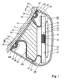
- electroacoustic underwater antenna is connected to an antenna support 10, z. B. attached to the hull of a submarine.
- the underwater antenna has a horizontal length limited in cultivation position I ( Fig. 2 ) from Z. B. one to two meters.
- Fig. 1 For the realization of a submarine usually on the port and starboard arranged side antenna several such Fig. 1 shown in cross-section underwater antennas horizontally strung together without spacing.
- the underwater antenna has a reflector 11 which is set acoustically decoupled via resilient elements on the antenna carrier 10.
- the reflector 11 is formed in a known manner as a spring-mass system and has, for example as a spring a soft material plate 12 and a lead plate 13 in conjunction with one of these superior in sound incidence composite of two thin aluminum plates 14, 15 with an intermediate, bending waves damping Layer 16, z. As rubber, on.
- a transducer assembly 17 of a plurality of electro-acoustic transducers, preferably hydrophones, fixed in a known manner.
- a plurality of vertically arranged with each other transducers which are formed for example of small ball ceramics, by embedding in an acoustically transparent potting compound to a transducer rod or a so-called.
- Stave 18 summarized. Several staves 18 are spaced apart along the length I of the underwater antenna. All staves 18 are attached to the top and bottom of the reflector 11, which is in Fig. 1 not shown separately.
- the reflector 11 is arranged by means of the resilient elements for the sake of reducing the radiated structure emitted by the antenna carrier 10 at a relatively large distance from the antenna support 10.
- the resilient elements an upper spring-elastic rocker 19 and a lower spring-elastic rocker 20.
- Both wings 19, 20 are made of glass fiber reinforced plastic and have the required spring constant adjusting shape and material thickness.
- Each rocker 19, 20 has a horizontal position in cultivation position I ( Fig. 2 ) corresponding to the dimension of the reflector 11 in the horizontal direction.
- Each rocker 19, 20 has a front abutment leg 191 and 201 for abutment and fixation on the reflector 11 and a rear abutment leg 192 and 202 for conditioning and attachment to the antenna support 10.
- the upper rocker 19 has an approximately U-shaped profile and the lower rocker 20 has a profile which is composed of two front and rear bearing limbs 201 and 202 containing U-shaped end portions and an integrally connecting them, stretched middle portion 203 ,
- the two wings 19, 20 are arranged so that the U-openings in the two wings 19, 20 face away from each other.
- the space between the upper rocker 19 and the lower rocker 20 is filled by a buoyant body 21, on the one hand extends to the antenna support 10 and on the other hand ends at a distance in front of the reflector 11.
- the buoyant body 21 At the antenna carrier 10 is the buoyant body 21 with the interposition of an elastic film 22, z. B. rubber cork, to.
- the distance between the buoyant body 21 and the reflector 11 is set so that the bottom of the front bearing leg 191 or 201 contained end portion of the upper rocker 19 and the lower rocker 20 from the buoyant body 21 is released.
- the attachment of the rocker 19, 20 on the antenna carrier 10 is carried out for each rocker 19, 20 at least two attachment points of the rear abutment legs 192 and 202.
- the antenna carrier 10 has so-called. Knag 23, which are lined up in the horizontal direction spaced from each other. In each case two rows of lugs 23 are vertically superimposed on the antenna support 10.
- Under lugs 23 are understood by the antenna support 10, that is from the hull of the submarine, protruding, preferably cylindrical mounting posts, which are each provided with a threaded hole 231.
- Each rear plant thigh 192 or 202 of the upper rocker 19 and the lower rocker 20 includes at least two elongated holes 24 (FIGS. Fig.
- each transverse power disc 26 is an elastic disc 27, preferably made of rubber cork, and placed on the elastic disc 27, a clamping plate 28 made of metal, preferably a steel disc, by screwing a screw 29 into the threaded bore 231 of the lugs 23 pressed until the tension pulley 28th to the end face of the knob 23 applies.
- a clamping plate 28 made of metal, preferably a steel disc, by screwing a screw 29 into the threaded bore 231 of the lugs 23 pressed until the tension pulley 28th to the end face of the knob 23 applies.
- a threaded blind hole 31 and 32 is introduced from the front side.
- a cap screw 33 is screwed with its screw shank 331, which passes through a corresponding through hole 34 ( Fig. 2 ) is passed in the upper rocker 19.
- Each front abutment leg 191 or 201 of the upper rocker 19 and the lower rocker 20 has two such, spaced by the greatest distance from each other through holes 34, so that at each front abutment leg 191 and 201 respectively two plastic cams 30 are screwed on each rocker 19 and 20 have a maximum distance from each other.
- the reflector 11 has, near its corner points, a total of four passage channels 35 stepped in diameter, via which the reflector 11 is exposed to the plastic cams 30 and fastened to the plastic cams 30.
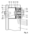
- Fig. 4 the attachment of the reflector 11 to the front abutment leg 191 of the upper rocker 19 is shown in detail, which applies to all attachment points of the reflector 11.
- the passageway 35 has a larger diameter rear channel portion 351, which engages over the rear cam portion 301 of the plastic cam 30 with little play, and a smaller diameter front channel portion 352 whose clear diameter is significantly larger than the outer diameter of the front cam portion 302.
- a radial shoulder 353 is formed with which the reflector 11 with the interposition of an elastic disc 37 on the front cam portion 302 surrounding annular end face of the rear cam portion 301 rests.
- a resilient sleeve 36 is inserted, which is axially clamped between the end face of the rear cam portion 301 and a metallic clamping plate 38.
- the clamping disk 38 is fixed on the end face of the front cam portion 302 by means of a cap screw 39, the screw shaft 391 of which is passed through the tensioning disk 38 and screwed into the threaded blind hole 32 in the front cam portion 302.
- the clamping disk 38 protrudes radially beyond the sleeve 36 and presses an elastic disk 40 onto the reflector 11.
- the two elastic discs 37, 40 are preferably made of rubber cork.
- the thus constructed and fixed to the antenna support 10 reflector 11 with superior transducer assembly 17 is on the front facing away from the antenna carrier 10 front acoustically transparent enveloping body 41 set.
- the enveloping body 41 is a laminate of two outer layers 411 of glass fiber reinforced plastic and an intermediate, significantly thicker rubber layer 412 (FIG. Fig. 6 ) and is attached to the two wings 19, 20.
- FIG. Fig. 1 As in Fig. 1 is shown, the enveloping body 12 at the free end of the rear abutment leg 192 of the upper rocker 19 and the middle portion 203 of the lower rocker 20 is fixed. In both cases, the determination takes place in the manner of a so-called.
- FIG. 1 illustrated embodiment is formed on the rocker 19 and 20 respectively forming head 42 which is encompassed by a molded into the Hüllève41 shell or pan 43.
- cover 44 releasably secured, which is fixed on the one hand on the enveloping body 41 and on the other hand at the free end of the butt Graschenkels 202 of the lower rocker 20 and the U-opening of the rear U-shaped end portion of the lower rocker 20 closes.
- the enclosed by the enveloping body 41 with cover 44 and the antenna support 10 space in which the reflector 11 with transducer assembly 17 and the swing system are housed with buoyant body 21 is flooded.
- an elastic disc 48 preferably made of rubber cork, pushed and the envelope body with the recess 46 positively pressed onto the studs 45, so that the enveloping body 41 via the elastic disc 48 to the rear abutment leg 192 of the upper rocker 19 applies.
- a clamping plate 49 made of metal is positively inserted, which is provided with a central through hole 491 with a Einfasung for the countersunk head of a countersunk screw 50.
- the countersunk screw 50 guided through the through hole 491 with its screw shank 501 is screwed into a threaded blind hole 51 held in the burl 45 and thereby secures the tensioning disc 49 on the end face of the burl 45, wherein the tensioning disc 49 engages the enveloping body 41 via the elastic disc 48 on the rear abutment leg 192 of the upper rocker 19 presses.
Landscapes
- Engineering & Computer Science (AREA)
- Physics & Mathematics (AREA)
- Acoustics & Sound (AREA)
- Multimedia (AREA)
- Radar, Positioning & Navigation (AREA)
- Mechanical Engineering (AREA)
- Aviation & Aerospace Engineering (AREA)
- Electromagnetism (AREA)
- Aerials With Secondary Devices (AREA)
- Details Of Aerials (AREA)
- Support Of Aerials (AREA)
- Measurement Of Velocity Or Position Using Acoustic Or Ultrasonic Waves (AREA)
Applications Claiming Priority (1)
| Application Number | Priority Date | Filing Date | Title |
|---|---|---|---|
| DE102009018624A DE102009018624B3 (de) | 2009-04-23 | 2009-04-23 | Elektroakustische Unterwasserantenne |
Publications (2)
| Publication Number | Publication Date |
|---|---|
| EP2244249A1 true EP2244249A1 (fr) | 2010-10-27 |
| EP2244249B1 EP2244249B1 (fr) | 2013-03-20 |
Family
ID=42235684
Family Applications (1)
| Application Number | Title | Priority Date | Filing Date |
|---|---|---|---|
| EP10157817A Active EP2244249B1 (fr) | 2009-04-23 | 2010-03-25 | Antenne électro-acoustique sous-marine |
Country Status (9)
| Country | Link |
|---|---|
| US (1) | US8400878B2 (fr) |
| EP (1) | EP2244249B1 (fr) |
| KR (1) | KR101116107B1 (fr) |
| AU (1) | AU2010201124B2 (fr) |
| CA (1) | CA2701320C (fr) |
| DE (1) | DE102009018624B3 (fr) |
| ES (1) | ES2405751T3 (fr) |
| IL (1) | IL204765A (fr) |
| RU (1) | RU2449495C2 (fr) |
Families Citing this family (9)
| Publication number | Priority date | Publication date | Assignee | Title |
|---|---|---|---|---|
| FR2991661B1 (fr) | 2012-06-11 | 2014-08-08 | Dcns | Structure d'engin sous-marin tel qu'un sous-marin |
| FR3015785B1 (fr) * | 2013-12-20 | 2015-12-25 | Thales Sa | Antenne omnidirectionnelle compacte pour sonar trempe |
| US11091235B2 (en) | 2018-06-07 | 2021-08-17 | Hobie Cat Ip, Llc | Retractable hull mounting data collecting system |
| WO2020010037A1 (fr) * | 2018-07-05 | 2020-01-09 | Commscope Technologies Llc | Ensemble rondelle pour montures d'antenne |
| KR102079059B1 (ko) * | 2019-10-14 | 2020-02-19 | 이상욱 | 잠수함의 센서 설치용 파운데이션 블록 어셈블리 |
| DE102020202776A1 (de) * | 2020-03-04 | 2021-09-09 | Atlas Elektronik Gmbh | Reflektor für Wasserschallwandler |
| US11395064B1 (en) | 2021-01-12 | 2022-07-19 | Raytheon Company | Vibration damping acoustic array |
| CN113978674B (zh) * | 2021-12-08 | 2023-03-17 | 西湖大学 | 一种水下航行器 |
| CN116331456B (zh) * | 2023-03-17 | 2023-11-24 | 中国科学院声学研究所 | 一种用于无人潜航器的舷侧阵组件 |
Citations (3)
| Publication number | Priority date | Publication date | Assignee | Title |
|---|---|---|---|---|
| DE3642747C2 (fr) | 1986-12-15 | 1991-05-29 | Krupp Atlas Elektronik Gmbh, 2800 Bremen, De | |
| DE3834669A1 (de) | 1988-10-12 | 1996-07-04 | Stn Atlas Elektronik Gmbh | Akustische Dämmungsvorrichtung |
| DE102006060796A1 (de) * | 2006-12-21 | 2008-06-26 | Atlas Elektronik Gmbh | Unterwasserantenne |
Family Cites Families (11)
| Publication number | Priority date | Publication date | Assignee | Title |
|---|---|---|---|---|
| EP0531869B1 (fr) * | 1991-09-11 | 1997-01-08 | SIEMENS SOLAR GmbH | Pince de montage |
| DE4339798A1 (de) * | 1993-11-23 | 1995-05-24 | Stn Atlas Elektronik Gmbh | Elektroakustische Wandleranordnung |
| RU2130402C1 (ru) * | 1998-01-20 | 1999-05-20 | Центральное конструкторское бюро морской техники "Рубин" | Носовая оконечность подводной лодки |
| RU2167499C2 (ru) * | 1999-06-01 | 2001-05-20 | Государственное унитарное предприятие "Центральный научно-исследовательский институт "Морфизприбор" | Линейный модуль гидроакустической антенны |
| FR2818081B1 (fr) * | 2000-12-08 | 2003-04-11 | Thomson Marconi Sonar Sas | Sonar de coque pour batiment naval |
| RU2217885C2 (ru) * | 2001-12-24 | 2003-11-27 | Федеральное государственное унитарное предприятие "Центральный научно-исследовательский институт "Морфизприбор" | Многоэлементная двумерная дискретная гидроакустическая антенна |
| US7236427B1 (en) * | 2004-03-12 | 2007-06-26 | Swce | Vessel hull transducer modular mounting system |
| DE102004038033B3 (de) * | 2004-08-05 | 2005-10-13 | Atlas Elektronik Gmbh | Verfahren zur Herstellung einer Antennensektion einer Unterwasserantenne und Antennensektion für eine flächenhafte Unterwasserantenne |
| US7548490B2 (en) * | 2006-07-25 | 2009-06-16 | Snyder Ricky L | Transducer transom adapter |
| DE102007053801B3 (de) * | 2007-11-12 | 2008-12-11 | Atlas Elektronik Gmbh | Unterwasserantenne |
| DE202008010210U1 (de) * | 2008-07-31 | 2008-10-09 | Claus Groth Gmbh | Federvorrichtung für Liegemöbel |
-
2009
- 2009-04-23 DE DE102009018624A patent/DE102009018624B3/de not_active Expired - Fee Related
-
2010
- 2010-03-22 AU AU2010201124A patent/AU2010201124B2/en not_active Ceased
- 2010-03-25 ES ES10157817T patent/ES2405751T3/es active Active
- 2010-03-25 IL IL204765A patent/IL204765A/en active IP Right Grant
- 2010-03-25 EP EP10157817A patent/EP2244249B1/fr active Active
- 2010-04-22 RU RU2010116045/28A patent/RU2449495C2/ru active
- 2010-04-22 CA CA2701320A patent/CA2701320C/fr active Active
- 2010-04-23 US US12/766,336 patent/US8400878B2/en active Active
- 2010-04-23 KR KR1020100038088A patent/KR101116107B1/ko active Active
Patent Citations (3)
| Publication number | Priority date | Publication date | Assignee | Title |
|---|---|---|---|---|
| DE3642747C2 (fr) | 1986-12-15 | 1991-05-29 | Krupp Atlas Elektronik Gmbh, 2800 Bremen, De | |
| DE3834669A1 (de) | 1988-10-12 | 1996-07-04 | Stn Atlas Elektronik Gmbh | Akustische Dämmungsvorrichtung |
| DE102006060796A1 (de) * | 2006-12-21 | 2008-06-26 | Atlas Elektronik Gmbh | Unterwasserantenne |
Also Published As
| Publication number | Publication date |
|---|---|
| CA2701320A1 (fr) | 2010-10-23 |
| EP2244249B1 (fr) | 2013-03-20 |
| US20100271907A1 (en) | 2010-10-28 |
| AU2010201124B2 (en) | 2011-06-09 |
| US8400878B2 (en) | 2013-03-19 |
| KR101116107B1 (ko) | 2012-02-17 |
| CA2701320C (fr) | 2014-08-12 |
| DE102009018624B3 (de) | 2010-11-04 |
| RU2010116045A (ru) | 2011-10-27 |
| IL204765A0 (en) | 2010-11-30 |
| RU2449495C2 (ru) | 2012-04-27 |
| AU2010201124A1 (en) | 2010-11-11 |
| KR20100117049A (ko) | 2010-11-02 |
| IL204765A (en) | 2014-11-30 |
| ES2405751T3 (es) | 2013-06-03 |
Similar Documents
| Publication | Publication Date | Title |
|---|---|---|
| EP2244249B1 (fr) | Antenne électro-acoustique sous-marine | |
| EP2200017B1 (fr) | Antenne d'eau souterraine | |
| EP0654953B1 (fr) | Arrangement de transducteurs électroacoustiques | |
| EP2345025B1 (fr) | Antenne sous-marine | |
| EP0214525B1 (fr) | Véhicule sous-marin | |
| EP2351018B1 (fr) | Antenne sous-marine | |
| DE102007053801B3 (de) | Unterwasserantenne | |
| DE3834669A1 (de) | Akustische Dämmungsvorrichtung | |
| DE102006060796B4 (de) | Unterwasserantenne | |
| DE10323493B3 (de) | Unterwasserantenne | |
| DE102008052352B3 (de) | Vorrichtung zur Befestigung einer Unterwasserantenne | |
| DE102009059902B3 (de) | Reflektoreinrichtung zur Anbringung einer zu einer Unterwasserantenne zugehörigen Wandleranordnung an eine Bootswand | |
| EP2351145B1 (fr) | Antenne sous-marine | |
| EP1774509B1 (fr) | Dispositif convertisseur electroacoustique pour antennes immergees | |
| DE3440747C2 (fr) | ||
| DE102006060795B3 (de) | Unterwasserantenne | |
| EP2758807B1 (fr) | Module support pour une antenne sous-marine et antenne sous-marine pourvue d'un module support de ce type | |
| DE8702068U1 (de) | Stromversorgungsgerät | |
| DE8801442U1 (de) | Befestigungsvorrichtung für eine Schalldämmplatte |
Legal Events
| Date | Code | Title | Description |
|---|---|---|---|
| PUAI | Public reference made under article 153(3) epc to a published international application that has entered the european phase |
Free format text: ORIGINAL CODE: 0009012 |
|
| AK | Designated contracting states |
Kind code of ref document: A1 Designated state(s): AT BE BG CH CY CZ DE DK EE ES FI FR GB GR HR HU IE IS IT LI LT LU LV MC MK MT NL NO PL PT RO SE SI SK SM TR |
|
| 17P | Request for examination filed |
Effective date: 20110202 |
|
| GRAP | Despatch of communication of intention to grant a patent |
Free format text: ORIGINAL CODE: EPIDOSNIGR1 |
|
| RIC1 | Information provided on ipc code assigned before grant |
Ipc: B63G 8/39 20060101ALI20120911BHEP Ipc: G10K 11/00 20060101AFI20120911BHEP |
|
| GRAS | Grant fee paid |
Free format text: ORIGINAL CODE: EPIDOSNIGR3 |
|
| GRAA | (expected) grant |
Free format text: ORIGINAL CODE: 0009210 |
|
| RIN1 | Information on inventor provided before grant (corrected) |
Inventor name: HOFFMANN CHRISTOPH Inventor name: LINDNER JUERGEN Inventor name: FOGGE DIRK-OLIVER |
|
| AK | Designated contracting states |
Kind code of ref document: B1 Designated state(s): AT BE BG CH CY CZ DE DK EE ES FI FR GB GR HR HU IE IS IT LI LT LU LV MC MK MT NL NO PL PT RO SE SI SK SM TR |
|
| REG | Reference to a national code |
Ref country code: GB Ref legal event code: FG4D Free format text: NOT ENGLISH |
|
| REG | Reference to a national code |
Ref country code: CH Ref legal event code: EP |
|
| REG | Reference to a national code |
Ref country code: IE Ref legal event code: FG4D Free format text: LANGUAGE OF EP DOCUMENT: GERMAN |
|
| REG | Reference to a national code |
Ref country code: AT Ref legal event code: REF Ref document number: 602495 Country of ref document: AT Kind code of ref document: T Effective date: 20130415 |
|
| REG | Reference to a national code |
Ref country code: DE Ref legal event code: R096 Ref document number: 502010002586 Country of ref document: DE Effective date: 20130516 |
|
| REG | Reference to a national code |
Ref country code: ES Ref legal event code: FG2A Ref document number: 2405751 Country of ref document: ES Kind code of ref document: T3 Effective date: 20130603 |
|
| REG | Reference to a national code |
Ref country code: NL Ref legal event code: T3 |
|
| REG | Reference to a national code |
Ref country code: SE Ref legal event code: TRGR |
|
| PG25 | Lapsed in a contracting state [announced via postgrant information from national office to epo] |
Ref country code: LT Free format text: LAPSE BECAUSE OF FAILURE TO SUBMIT A TRANSLATION OF THE DESCRIPTION OR TO PAY THE FEE WITHIN THE PRESCRIBED TIME-LIMIT Effective date: 20130320 Ref country code: BG Free format text: LAPSE BECAUSE OF FAILURE TO SUBMIT A TRANSLATION OF THE DESCRIPTION OR TO PAY THE FEE WITHIN THE PRESCRIBED TIME-LIMIT Effective date: 20130620 |
|
| REG | Reference to a national code |
Ref country code: LT Ref legal event code: MG4D |
|
| PG25 | Lapsed in a contracting state [announced via postgrant information from national office to epo] |
Ref country code: FI Free format text: LAPSE BECAUSE OF FAILURE TO SUBMIT A TRANSLATION OF THE DESCRIPTION OR TO PAY THE FEE WITHIN THE PRESCRIBED TIME-LIMIT Effective date: 20130320 Ref country code: SI Free format text: LAPSE BECAUSE OF FAILURE TO SUBMIT A TRANSLATION OF THE DESCRIPTION OR TO PAY THE FEE WITHIN THE PRESCRIBED TIME-LIMIT Effective date: 20130320 Ref country code: GR Free format text: LAPSE BECAUSE OF FAILURE TO SUBMIT A TRANSLATION OF THE DESCRIPTION OR TO PAY THE FEE WITHIN THE PRESCRIBED TIME-LIMIT Effective date: 20130621 Ref country code: LV Free format text: LAPSE BECAUSE OF FAILURE TO SUBMIT A TRANSLATION OF THE DESCRIPTION OR TO PAY THE FEE WITHIN THE PRESCRIBED TIME-LIMIT Effective date: 20130320 |
|
| REG | Reference to a national code |
Ref country code: NO Ref legal event code: T2 Effective date: 20130320 |
|
| BERE | Be: lapsed |
Owner name: ATLAS ELEKTRONIK G.M.B.H. Effective date: 20130331 |
|
| PG25 | Lapsed in a contracting state [announced via postgrant information from national office to epo] |
Ref country code: HR Free format text: LAPSE BECAUSE OF FAILURE TO SUBMIT A TRANSLATION OF THE DESCRIPTION OR TO PAY THE FEE WITHIN THE PRESCRIBED TIME-LIMIT Effective date: 20130320 |
|
| PG25 | Lapsed in a contracting state [announced via postgrant information from national office to epo] |
Ref country code: MC Free format text: LAPSE BECAUSE OF NON-PAYMENT OF DUE FEES Effective date: 20130331 Ref country code: EE Free format text: LAPSE BECAUSE OF FAILURE TO SUBMIT A TRANSLATION OF THE DESCRIPTION OR TO PAY THE FEE WITHIN THE PRESCRIBED TIME-LIMIT Effective date: 20130320 Ref country code: SK Free format text: LAPSE BECAUSE OF FAILURE TO SUBMIT A TRANSLATION OF THE DESCRIPTION OR TO PAY THE FEE WITHIN THE PRESCRIBED TIME-LIMIT Effective date: 20130320 Ref country code: IS Free format text: LAPSE BECAUSE OF FAILURE TO SUBMIT A TRANSLATION OF THE DESCRIPTION OR TO PAY THE FEE WITHIN THE PRESCRIBED TIME-LIMIT Effective date: 20130720 Ref country code: PT Free format text: LAPSE BECAUSE OF FAILURE TO SUBMIT A TRANSLATION OF THE DESCRIPTION OR TO PAY THE FEE WITHIN THE PRESCRIBED TIME-LIMIT Effective date: 20130722 Ref country code: CZ Free format text: LAPSE BECAUSE OF FAILURE TO SUBMIT A TRANSLATION OF THE DESCRIPTION OR TO PAY THE FEE WITHIN THE PRESCRIBED TIME-LIMIT Effective date: 20130320 Ref country code: RO Free format text: LAPSE BECAUSE OF FAILURE TO SUBMIT A TRANSLATION OF THE DESCRIPTION OR TO PAY THE FEE WITHIN THE PRESCRIBED TIME-LIMIT Effective date: 20130320 |
|
| PG25 | Lapsed in a contracting state [announced via postgrant information from national office to epo] |
Ref country code: PL Free format text: LAPSE BECAUSE OF FAILURE TO SUBMIT A TRANSLATION OF THE DESCRIPTION OR TO PAY THE FEE WITHIN THE PRESCRIBED TIME-LIMIT Effective date: 20130320 Ref country code: CY Free format text: LAPSE BECAUSE OF FAILURE TO SUBMIT A TRANSLATION OF THE DESCRIPTION OR TO PAY THE FEE WITHIN THE PRESCRIBED TIME-LIMIT Effective date: 20130320 |
|
| REG | Reference to a national code |
Ref country code: IE Ref legal event code: MM4A |
|
| PLBE | No opposition filed within time limit |
Free format text: ORIGINAL CODE: 0009261 |
|
| STAA | Information on the status of an ep patent application or granted ep patent |
Free format text: STATUS: NO OPPOSITION FILED WITHIN TIME LIMIT |
|
| PG25 | Lapsed in a contracting state [announced via postgrant information from national office to epo] |
Ref country code: IE Free format text: LAPSE BECAUSE OF NON-PAYMENT OF DUE FEES Effective date: 20130325 Ref country code: BE Free format text: LAPSE BECAUSE OF NON-PAYMENT OF DUE FEES Effective date: 20130331 Ref country code: DK Free format text: LAPSE BECAUSE OF FAILURE TO SUBMIT A TRANSLATION OF THE DESCRIPTION OR TO PAY THE FEE WITHIN THE PRESCRIBED TIME-LIMIT Effective date: 20130320 |
|
| 26N | No opposition filed |
Effective date: 20140102 |
|
| REG | Reference to a national code |
Ref country code: DE Ref legal event code: R097 Ref document number: 502010002586 Country of ref document: DE Effective date: 20140102 |
|
| PG25 | Lapsed in a contracting state [announced via postgrant information from national office to epo] |
Ref country code: MT Free format text: LAPSE BECAUSE OF FAILURE TO SUBMIT A TRANSLATION OF THE DESCRIPTION OR TO PAY THE FEE WITHIN THE PRESCRIBED TIME-LIMIT Effective date: 20130320 |
|
| REG | Reference to a national code |
Ref country code: CH Ref legal event code: PL |
|
| PG25 | Lapsed in a contracting state [announced via postgrant information from national office to epo] |
Ref country code: LI Free format text: LAPSE BECAUSE OF NON-PAYMENT OF DUE FEES Effective date: 20140331 Ref country code: CH Free format text: LAPSE BECAUSE OF NON-PAYMENT OF DUE FEES Effective date: 20140331 |
|
| PG25 | Lapsed in a contracting state [announced via postgrant information from national office to epo] |
Ref country code: SM Free format text: LAPSE BECAUSE OF FAILURE TO SUBMIT A TRANSLATION OF THE DESCRIPTION OR TO PAY THE FEE WITHIN THE PRESCRIBED TIME-LIMIT Effective date: 20130320 |
|
| PG25 | Lapsed in a contracting state [announced via postgrant information from national office to epo] |
Ref country code: LU Free format text: LAPSE BECAUSE OF NON-PAYMENT OF DUE FEES Effective date: 20130325 Ref country code: MK Free format text: LAPSE BECAUSE OF FAILURE TO SUBMIT A TRANSLATION OF THE DESCRIPTION OR TO PAY THE FEE WITHIN THE PRESCRIBED TIME-LIMIT Effective date: 20130320 Ref country code: HU Free format text: LAPSE BECAUSE OF FAILURE TO SUBMIT A TRANSLATION OF THE DESCRIPTION OR TO PAY THE FEE WITHIN THE PRESCRIBED TIME-LIMIT; INVALID AB INITIO Effective date: 20100325 |
|
| REG | Reference to a national code |
Ref country code: FR Ref legal event code: PLFP Year of fee payment: 7 |
|
| REG | Reference to a national code |
Ref country code: AT Ref legal event code: MM01 Ref document number: 602495 Country of ref document: AT Kind code of ref document: T Effective date: 20150325 |
|
| PG25 | Lapsed in a contracting state [announced via postgrant information from national office to epo] |
Ref country code: AT Free format text: LAPSE BECAUSE OF NON-PAYMENT OF DUE FEES Effective date: 20150325 |
|
| REG | Reference to a national code |
Ref country code: FR Ref legal event code: PLFP Year of fee payment: 8 |
|
| REG | Reference to a national code |
Ref country code: FR Ref legal event code: PLFP Year of fee payment: 9 |
|
| P01 | Opt-out of the competence of the unified patent court (upc) registered |
Effective date: 20230530 |
|
| PGFP | Annual fee paid to national office [announced via postgrant information from national office to epo] |
Ref country code: DE Payment date: 20250319 Year of fee payment: 16 |
|
| PGFP | Annual fee paid to national office [announced via postgrant information from national office to epo] |
Ref country code: ES Payment date: 20250425 Year of fee payment: 16 |
|
| REG | Reference to a national code |
Ref country code: DE Ref legal event code: R081 Ref document number: 502010002586 Country of ref document: DE Owner name: TKMS ATLAS ELEKTRONIK GMBH, DE Free format text: FORMER OWNER: ATLAS ELEKTRONIK GMBH, 28309 BREMEN, DE |
|
| REG | Reference to a national code |
Ref country code: DE Ref legal event code: R084 Ref document number: 502010002586 Country of ref document: DE |
|
| PGFP | Annual fee paid to national office [announced via postgrant information from national office to epo] |
Ref country code: SE Payment date: 20260319 Year of fee payment: 17 |
|
| PGFP | Annual fee paid to national office [announced via postgrant information from national office to epo] |
Ref country code: GB Payment date: 20260324 Year of fee payment: 17 |
|
| PGFP | Annual fee paid to national office [announced via postgrant information from national office to epo] |
Ref country code: NO Payment date: 20260323 Year of fee payment: 17 |
|
| PGFP | Annual fee paid to national office [announced via postgrant information from national office to epo] |
Ref country code: IT Payment date: 20260324 Year of fee payment: 17 |
|
| PGFP | Annual fee paid to national office [announced via postgrant information from national office to epo] |
Ref country code: NL Payment date: 20260319 Year of fee payment: 17 |
|
| PGFP | Annual fee paid to national office [announced via postgrant information from national office to epo] |
Ref country code: FR Payment date: 20260320 Year of fee payment: 17 |
|
| PGFP | Annual fee paid to national office [announced via postgrant information from national office to epo] |
Ref country code: TR Payment date: 20260323 Year of fee payment: 17 |