EP2244634B1 - High-resolution quasi-static setup for x-ray imaging with distributed sources - Google Patents
High-resolution quasi-static setup for x-ray imaging with distributed sources Download PDFInfo
- Publication number
- EP2244634B1 EP2244634B1 EP09711575.2A EP09711575A EP2244634B1 EP 2244634 B1 EP2244634 B1 EP 2244634B1 EP 09711575 A EP09711575 A EP 09711575A EP 2244634 B1 EP2244634 B1 EP 2244634B1
- Authority
- EP
- European Patent Office
- Prior art keywords
- distributed
- ray source
- source structure
- ray
- detector
- Prior art date
- Legal status (The legal status is an assumption and is not a legal conclusion. Google has not performed a legal analysis and makes no representation as to the accuracy of the status listed.)
- Not-in-force
Links
- 238000003384 imaging method Methods 0.000 title claims description 39
- 238000000034 method Methods 0.000 claims description 51
- 238000005070 sampling Methods 0.000 claims description 8
- 230000001131 transforming effect Effects 0.000 claims description 6
- 238000012545 processing Methods 0.000 claims description 3
- 230000010354 integration Effects 0.000 claims description 2
- 239000011295 pitch Substances 0.000 description 26
- 210000000056 organ Anatomy 0.000 description 10
- OKTJSMMVPCPJKN-UHFFFAOYSA-N Carbon Chemical compound [C] OKTJSMMVPCPJKN-UHFFFAOYSA-N 0.000 description 6
- 239000002041 carbon nanotube Substances 0.000 description 6
- 229910021393 carbon nanotube Inorganic materials 0.000 description 6
- 230000003068 static effect Effects 0.000 description 3
- 238000001514 detection method Methods 0.000 description 2
- 238000010894 electron beam technology Methods 0.000 description 2
- 210000004072 lung Anatomy 0.000 description 2
- 239000002184 metal Substances 0.000 description 2
- 239000002071 nanotube Substances 0.000 description 2
- 230000005855 radiation Effects 0.000 description 2
- 238000002591 computed tomography Methods 0.000 description 1
- 230000003247 decreasing effect Effects 0.000 description 1
- 230000001419 dependent effect Effects 0.000 description 1
- 238000011161 development Methods 0.000 description 1
- 238000002059 diagnostic imaging Methods 0.000 description 1
- 230000005684 electric field Effects 0.000 description 1
- 230000003116 impacting effect Effects 0.000 description 1
- 239000011229 interlayer Substances 0.000 description 1
- 239000011159 matrix material Substances 0.000 description 1
- 239000002086 nanomaterial Substances 0.000 description 1
- 238000013021 overheating Methods 0.000 description 1
- 230000003252 repetitive effect Effects 0.000 description 1
- 239000000758 substrate Substances 0.000 description 1
- 230000001360 synchronised effect Effects 0.000 description 1
- 230000009466 transformation Effects 0.000 description 1
Images


Classifications
-
- A—HUMAN NECESSITIES
- A61—MEDICAL OR VETERINARY SCIENCE; HYGIENE
- A61B—DIAGNOSIS; SURGERY; IDENTIFICATION
- A61B6/00—Apparatus or devices for radiation diagnosis; Apparatus or devices for radiation diagnosis combined with radiation therapy equipment
- A61B6/02—Arrangements for diagnosis sequentially in different planes; Stereoscopic radiation diagnosis
- A61B6/025—Tomosynthesis
-
- A—HUMAN NECESSITIES
- A61—MEDICAL OR VETERINARY SCIENCE; HYGIENE
- A61B—DIAGNOSIS; SURGERY; IDENTIFICATION
- A61B6/00—Apparatus or devices for radiation diagnosis; Apparatus or devices for radiation diagnosis combined with radiation therapy equipment
- A61B6/40—Arrangements for generating radiation specially adapted for radiation diagnosis
- A61B6/4007—Arrangements for generating radiation specially adapted for radiation diagnosis characterised by using a plurality of source units
-
- A—HUMAN NECESSITIES
- A61—MEDICAL OR VETERINARY SCIENCE; HYGIENE
- A61B—DIAGNOSIS; SURGERY; IDENTIFICATION
- A61B6/00—Apparatus or devices for radiation diagnosis; Apparatus or devices for radiation diagnosis combined with radiation therapy equipment
- A61B6/02—Arrangements for diagnosis sequentially in different planes; Stereoscopic radiation diagnosis
- A61B6/027—Arrangements for diagnosis sequentially in different planes; Stereoscopic radiation diagnosis characterised by the use of a particular data acquisition trajectory, e.g. helical or spiral
Definitions
- the present invention relates to the field of medical imaging, more generally to the field of non-invasive imaging.
- the present invention relates to a method of acquiring X-ray image data of an imaging volume and an X-ray imaging system with a distributed X-ray source structure having a plurality of single source elements.
- X-ray imaging systems are utilized for various applications in both medical and non-medical fields.
- Tomographic imaging systems with distributed sources enable a scanning of the object without moving the X-ray source structure and/or detector just by switching sequentially the single X-ray source structures (no moving elements).
- the limitation of the spatial resolution of the X-ray images is linked to the sub-sampling and data acquisition of the projections that is limited by the number and position of single source elements.
- the pitch of a distributed X-ray source structure limits the number of possible projections in a static geometry. Depending on the number, complexity and size of the single source elements of the source structure only limited spatial resolution can be achieved.
- US 2007/0009088 discloses a system and method for imaging using distributed X-ray sources.
- the system includes a distributed X-ray source and a detector.
- the distributed X-ray source is configured to emit X-rays from a plurality of emission points arranged in a linear, arcuate or curvilinear segment or a non-planar surface.
- the detector is configured to generate a plurality of signals in response to X-rays incident upon the detector.
- time is required to move the tube and allow the gantry to become stable during which the object remains unmoved.
- a stationary, distributed X-ray source would allow rapid switching of source positions, improved image quality since motion is eliminated.
- US 2007/0009081 A1 discloses a computed tomography device.
- the device comprises a distributed X-ray source.
- the X-ray source comprises a cathode with a plurality of individually programmable electron emitting units that each emit an electron beam upon an application of an electric field, an anode target that emits an X-ray beam upon impact by the emitted electron beam, and a collimator, and an X-ray detecting unit.
- a method for acquiring X-ray image data of an imaging volume uses a detector and a distributed X-ray source structure having a plurality of single source elements, wherein the single source elements are uniformly distributed with a common pitch to each other.
- the method comprises the steps of moving the distributed X-ray source structure and/or the detector with respect to the imaging volume, wherein the maximum moving distance d max of the distributed X-ray source structure during the acquisition of the X-ray image data is limited to the length l p of the pitch, emitting X-rays from the distributed X-ray source structure and generating a plurality of signals in response to the X-rays incident upon the detector.
- the plurality of single source elements of the distributed X-ray source structure is arranged lineary on an axis in a plane (1-dimension), or over an area of a plane (2-dimensional array). Both, the lineary arrangement or the 2-dimensional arrangement over the area may be arcuated with at least one predefined radius by the shape of a supporting structure.
- the pitch is herewith defined as the distance or angle between the midpoints of adjacent single source elements.
- the said pitch is equal for all elements in at least one direction.
- the pitch is called common pitch.
- the distributed x-ray source structure can be a linear, an arched, and/or an area X-ray source structure, it shall be understood that the distributed X-ray source have may be more than one common pitch in case of a 2-dimensional array in an exemplary embodiment.
- the movement of the distributed X-ray source structure may have different maximum moving distances d max of the distributed X-ray source structure in each moving direction during the acquisition of the X-ray image data.
- the limitation depends for different pitches on the length l pN or l pM in X or Y moving direction.
- the movement of the distributed X-ray source structure stops at the latest if midpoints (focal spots) of the single source elements arrives at the first emitting position of midpoints of adjacent single source elements.
- the movement of the distributed X-ray source structure follows the direction of a tangent vector at a defined location fitting the shape of the distributed X-ray source structure.
- the X-ray imaging system comprises a detector and a distributed X-ray source structure having a plurality of single source elements.
- the single source elements are uniformly distributed with a common pitch to each other
- the X-ray imaging system method is configured for acquiring X-ray image data of an imaging volume.
- the distributed X-ray source structure and/or the detector is configured to move with respect to the imaging volume, wherein the maximum moving distance d max of the distributed X-ray source structure during the acquisition of the X-ray image data is limited to the length l p of the pitch.
- the distributed X-ray source structure is configured to emit X-rays during a movement of the distributed X-ray source structure and/or the detector.
- the detector is configured to generate a plurality of signals in response to X-rays incident upon the detector during a movement of the distributed X-ray source structure and/or the detector.
- the maximum moving distance d max of the distributed X-ray source structure during the acquisition of the X-ray image data is further limited to 1/2, 1/3 or 1/4 of the length l p of the pitch.
- maximum moving distance d max 1/n * l p , with n ⁇ 1 are in the scope of the invention.
- a slow movement e.g. sinusoidal
- a few centimeter or even only millimeter of the distributed source structure in addition to a fast repetitive switching scheme allows a great increase in the spatial resolution and image quality since many more additional projections become available.
- full rotation like CT
- the velocity of the movement is preferably in-between the range from 0,1x10 -4 m/s to 5x10 -2 m/s.
- the movement distance of the source structure during acquisition is maximum the length of the common pitch of the distributed X-ray source structure and therefore, has to be only few centimeters or even millimeters.
- the pitch is preferably selected from a range between 1 mm and 40 cm.
- a common pitch selected from a range of 0,1 mm to 10 cm is possible by using e.g. nano tube emitters as single source elements.
- the movement velocity and/or moving distance during one detector frame integration period is limited to the tolerable spatial resolution requirement (movement artifact).
- the movement itself could be a continuous forth and back movement. It is not necessary to have a continuous rotation (like in CT) or a rotation along a part of the circular arc as "standard" tomosynthesis systems do.
- the complete mechanical setup is easy to implement and the advantage of the fast switching of the sources can be combined with a simple small distance movement to achieve very high resolution sampling.
- the movement of the source structure is equivalent to a sinusoidal movement.
- Said movement could be archived by using means for transforming rotation into linear movements, e.g. by using con rod and crank devices. Said rotation is preferably continuous.
- the actual position of the source structure, the imaging volume of an object to be examined and/or the detector is measured by measuring means.
- a relative position of said objects to each other is measured by measuring means.
- the method comprises measuring the actual position of the distributed X-ray source structure and/or the detector and/or an object to be examined during the movement of the distributed X-ray source structure and/or the detector.
- the movement is overlayed with repeated synchronized sequential switching of the single elements of the X-ray source structure for emitting, preferably along a scan trajectory.
- emitting of X-rays takes place during the movement of the distributed X-ray source structure and/or the detector.
- a motion actuator is used according to a further aspect. The requirement for such motion actuator is low with respect to velocity but a good position accuracy for the definition of the source position is necessary.
- the detector generating of a plurality of signals takes place during the movement of the distributed X-ray source structure and/or the detector.
- the position of the source is measured or calculated from the overlay of the position of the selected switched source element and the movement of the source array.
- the movement speed and the switching speed are linked in a way that for a complete acquisition a continuous trajectory with equidistant sampling points is achieved.
- the movement speed and the switching speed are linked in a way that for an acquisition of a predefined level of completeness a trajectory with preferably equidistant sampling points is achieved.
- the subject matter of the invention is preferably used for CT, ⁇ CT, tomosynthesis and other high resolution tomographic imaging applications.
- the method further comprises detecting a position and/or size of an object of special interest by processing means.
- the detection can be achieved by automatic interpreting a previously obtained data set of the imaging volume. For example, a part of a patient body, the torso for instance, is examined by the X-ray system in a first examination procedure.
- This first examination procedure may be statically with regard to the X-ray source structure. In this first examination procedure the emitting X-ray elements are switched for emitting separately, or in predefined groups or all at once.
- No moving is necessary during the first examination procedure.
- a data set obtained from the detector signals of the said first examination procedure is examined to locate an object of special interest. This examination could be executed automatically with one of the methods well-known in the art, or manually by the operator.
- the object of special interest may be an organ, e.g. the lung, the heart, or parts of an organ.
- a group of single source elements from the plurality of single source elements are selected in a next step wherein the selection depends on the size and/or the position of the object of special interest.
- Preferably all single source elements are selected, whose emitting beam/focus overlays at least partially the volume of the organ of special interest.
- selecting may be executed for more than one organ.
- the selection of single sources could be done manually by an operator.
- the selection of single sources could be done automatically by using a image model with typical object sizes and positions.
- the operator may define one object of special interest.
- the single source elements whose emitting focus crosses the model images relevant area of the selected organ are selected for later (second) examination according to claim 1 of the method.
- selection criteria may be applied in one other embodiment of the invention, wherein the selection criteria comprises image quality, total dose of emitted radiation, user decision, quantitative acquisition threshold, ration of resolution, acquisition time.
- the radiation exposure is significantly reduced, nevertheless the examination of the relevant part of the imaging volume, the object of special interest, is examined with high special resolution in a most accurate manner.
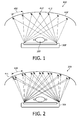
- a tomosynthesis system 100' for executing a method for acquiring X-ray image data of an imaging volume of a patients body 200' is shown in Fig. 1 .
- the system comprises a detector 300' and a distributed X-ray source structure 400' having a plurality of single source elements 410', wherein the single source elements 410' are uniformly distributed with a common pitch 450' to each other (arrow).
- the single source elements are Carbon Nano Tubes (CNT). Neither the distributed X-ray source structure 400' nor the detector 300' are able to move in this embodiment.
- Fig. 2 shows a quasistatic tomosynthesis system 200 for executing a method according to claim 1.
- the system comprises a detector 300 and a distributed X-ray source structure 400 having a plurality of fixed single source elements 410, wherein the single source elements 410 are uniformly distributed with a common pitch 450 to each other (arrow).
- the single source elements are Carbon Nano Tubes (CNT).
- the system 200 enables to move the distributed X-ray source structure 200 with respect to the imaging volume.
- the system 200 enables to move the distributed X-ray source 200 structure and the detector 300 with respect to the imaging volume in another embodiment.
- the system 200 enables to move the detector 300 with respect to the imaging volume in another embodiment.
- the maximum moving distance d max of the distributed X-ray source structure during the acquisition of the X-ray image data is in each embodiment according to the invention always limited to the length l p of the pitch 450.
- X-rays are emitted with focus 460 from the distributed X-ray source structure.
- a smaller emitting focus of a few degrees, e.g. limited to 15°, 20° or 30° for each single emitting element is still possible.
- the distributed X-ray source is configured to emit X-rays from a plurality of emission points, the single source elements, arranged in a linear, arcuate or curvilinear segment or a non-planar or even planar surface.
- the trajectory of the movement of the source structure corresponds to the shape of the source structure.
- Each of the plurality of single source elements or individually programmable electron emitting units of the x-ray source structure can be operated in a particular sequence or as a group in a particular pattern to produce an emitted x-ray that illuminates the object in the system from a different angle, plane or other orientation.
- multiple detected x-ray radiation images can be produced during a movement of the source structure.
- the support (patient table) for the examined object is able to move.
- a multiple helical scanning of the imaging volume is possible.
- Fig. 3 shows an embodiment according to one aspect of the invention.
- Means 500 for transforming rotating movement as indicated by arrow 510 into linear movement as indicated by arrow 520 are realized by using a motor 515 with a gearwheel 516 and transformation means 540.
- a second gearwheel 530 with a con rod 542 is engaged with the gearwheel 516 of the motor 515.
- the con rod 542 is guided on one end in a slotted link 545.
- the distributed X-ray source structure 400" is fixed with fixation means 550 to the con rod 542 .
- the X-ray source structure 400" is able to move in a continuously forth and back movement (520). With the said embodiment the movement velocity of the X-ray source structure 400" changes in sinusoidal manner.
- X-ray imaging system further comprises means for transforming rotation in a linear movement for the distributed X-ray source structure.
- Fig. 4 shows a distributed X-ray source structure in form of an embodiment 401.
- the embodiment may comprise a field emission cathode structure comprising a nanostructure or nanotube film (dots 411 and circles 412) on a conducting substrate preferably with a desired metal interlayer 413, wherein the film is patterned and aligned with the openings in a gate electrode 414 to minimize overheating of the metal grid caused by bombardment with the field emitted electrons.
- the film forms the single source elements 411, 412.
- Non-active single source elements are shown as dots 411, emitting single source elements are shown as circles 412. All elements 411, 412 have a common pitch with a length l p .
- the distance between emitting elements 412 is exemplary shown with 3* l p .
- one exemplary method for acquiring image data comprises detecting a position and/or size of an object of special interest by processing means.
- the detection can be achieved by automatic interpreting a previously obtained data set of the imaging volume. For example, a part of a patient body, the torso for instance, is examined by the X-ray system in a first examination procedure 1000. In this first examination procedure the emitting X-ray elements are switched for emitting separately, or in predefined groups or all at once.
- Fig. 4 shows such a grid of emitting single source elements as circles 412. No moving is necessary during the first examination procedure.
- a data set obtained from the detector signals of the said first examination procedure is examined in the next step 2000 to locate an object of special interest. This examination could be executed automatically with one of the methods well known in the art (scout imaging), or manually by the operator.
- the object of special interest may be an organ, e.g. the lung, the heart, or parts of an organ.
- a group of single source elements from the plurality of single source elements are selected in a next step 3000 wherein the selection depends on the size and/or the positionofthe object of special interest.
- Preferably all single source elements are selected, whose emitting beam/focus overlays at least partially the volume of the organ of special interest.
- selecting may be executed for more than one organ.
- the selection of single sources could be done manually by an operator (step 2200).
- the selection of single sources could be done automatically by using a image model with typical object sizes and positions.
- the operator may define one object of special interest.
- the single source elements whose emitting focus crosses the model images relevant area of the selected organ are selected for later (second) examination according to claim 1 of the method (step 3000, 4000).
- the method according to claim 1 is executed in step 4000.
- the method comprises: moving (4200) the distributed X-ray source structure and/or the detector with respect to the imaging volume, wherein the maximum moving distance d max of the distributed X-ray source structure during the acquisition of the X-ray image data is limited to the length l p of the pitch; emitting (4400) X-rays from the distributed X-ray source structure, precisely from the selected single source elements, and generating (4600) a plurality of signals in response to the X-rays incident upon the detector. Precisely, only the previously selected single source elements and/or the single elements of the detector are switched for emitting in a predefinable progression during the movement of the X-ray source structure.
- step 5000 a final image of the image volume or a part of it is acquired in step 5000.
- radiation exposure is significantly reduced, nevertheless the examination of the relevant part of the imaging volume, the object of special interest, is examined with high special resolution in a most accurate manner.
Landscapes
- Health & Medical Sciences (AREA)
- Life Sciences & Earth Sciences (AREA)
- Medical Informatics (AREA)
- Engineering & Computer Science (AREA)
- Radiology & Medical Imaging (AREA)
- Molecular Biology (AREA)
- Biophysics (AREA)
- Nuclear Medicine, Radiotherapy & Molecular Imaging (AREA)
- Optics & Photonics (AREA)
- Pathology (AREA)
- Physics & Mathematics (AREA)
- Biomedical Technology (AREA)
- Heart & Thoracic Surgery (AREA)
- High Energy & Nuclear Physics (AREA)
- Surgery (AREA)
- Animal Behavior & Ethology (AREA)
- General Health & Medical Sciences (AREA)
- Public Health (AREA)
- Veterinary Medicine (AREA)
- Apparatus For Radiation Diagnosis (AREA)
- Analysing Materials By The Use Of Radiation (AREA)
Priority Applications (1)
| Application Number | Priority Date | Filing Date | Title |
|---|---|---|---|
| EP09711575.2A EP2244634B1 (en) | 2008-02-22 | 2009-02-19 | High-resolution quasi-static setup for x-ray imaging with distributed sources |
Applications Claiming Priority (3)
| Application Number | Priority Date | Filing Date | Title |
|---|---|---|---|
| EP08101905 | 2008-02-22 | ||
| PCT/IB2009/050690 WO2009104156A1 (en) | 2008-02-22 | 2009-02-19 | High-resolution quasi-static setup for x-ray imaging with distributed sources |
| EP09711575.2A EP2244634B1 (en) | 2008-02-22 | 2009-02-19 | High-resolution quasi-static setup for x-ray imaging with distributed sources |
Publications (2)
| Publication Number | Publication Date |
|---|---|
| EP2244634A1 EP2244634A1 (en) | 2010-11-03 |
| EP2244634B1 true EP2244634B1 (en) | 2016-11-30 |
Family
ID=40670951
Family Applications (1)
| Application Number | Title | Priority Date | Filing Date |
|---|---|---|---|
| EP09711575.2A Not-in-force EP2244634B1 (en) | 2008-02-22 | 2009-02-19 | High-resolution quasi-static setup for x-ray imaging with distributed sources |
Country Status (7)
| Country | Link |
|---|---|
| US (1) | US8491188B2 (ja) |
| EP (1) | EP2244634B1 (ja) |
| JP (1) | JP5575666B2 (ja) |
| CN (1) | CN101951837B (ja) |
| BR (1) | BRPI0908195A2 (ja) |
| RU (1) | RU2491019C2 (ja) |
| WO (1) | WO2009104156A1 (ja) |
Cited By (2)
| Publication number | Priority date | Publication date | Assignee | Title |
|---|---|---|---|---|
| US11051771B2 (en) | 2014-06-17 | 2021-07-06 | Xintek, Inc. | Stationary intraoral tomosynthesis imaging systems, methods, and computer readable media for three dimensional dental imaging |
| US12004890B2 (en) | 2018-10-26 | 2024-06-11 | Surround Medical Systems, Inc. | Intraoral tomosynthesis X-ray imaging device, system, and method with interchangeable collimator |
Families Citing this family (31)
| Publication number | Priority date | Publication date | Assignee | Title |
|---|---|---|---|---|
| WO2011033439A1 (en) * | 2009-09-15 | 2011-03-24 | Koninklijke Philips Electronics N.V. | Distributed x-ray source and x-ray imaging system comprising the same |
| DE102009058266B4 (de) * | 2009-12-14 | 2020-01-02 | Siemens Healthcare Gmbh | Medizinisches Röntgenaufnahmesystem |
| DE102010011662A1 (de) * | 2010-03-17 | 2011-09-22 | Siemens Aktiengesellschaft | Röntgensystem |
| DE102010028438A1 (de) * | 2010-04-30 | 2011-11-03 | Siemens Aktiengesellschaft | Verfahren zur Aufnahme von zu einem dreidimensionalen Bilddatensatz zu rekonstruierenden Projektionsbildern eines Objekts unter verschiedenen, durch eine Abtasttrajektorie beschriebenen Projektionswinkel und Röntgeneinrichtung |
| WO2013068888A1 (en) * | 2011-11-11 | 2013-05-16 | Koninklijke Philips Electronics N.V. | Enlarged angular gating window c-arm image acquisition |
| CN102551783A (zh) * | 2012-02-16 | 2012-07-11 | 邓敏 | 手术用双模态实时成像装置、系统及其方法 |
| CN103308535B (zh) * | 2012-03-09 | 2016-04-13 | 同方威视技术股份有限公司 | 用于射线扫描成像的设备和方法 |
| US9517036B2 (en) * | 2012-08-20 | 2016-12-13 | Varian Medical Systems, Inc. | Radiation imaging using very slow rotational technique |
| CN103776848B (zh) * | 2012-10-24 | 2017-08-29 | 同方威视技术股份有限公司 | 射线发射装置和成像系统 |
| CN103901486B (zh) * | 2012-12-27 | 2018-04-24 | 同方威视技术股份有限公司 | 人体背散射安检系统及其方法 |
| US10660580B2 (en) * | 2013-01-23 | 2020-05-26 | Carestream Health, Inc. | Directed X-ray fields for tomosynthesis |
| CN104458771B (zh) * | 2013-09-23 | 2017-01-18 | 同方威视技术股份有限公司 | 直线轨迹断层扫描装置以及透视成像装置 |
| CN106132302A (zh) * | 2013-11-06 | 2016-11-16 | 射线科学有限公司 | 包括多个x射线源的x射线成像设备 |
| JP5677596B2 (ja) * | 2014-01-15 | 2015-02-25 | キヤノン株式会社 | X線撮影装置 |
| CN105372269B (zh) | 2014-09-02 | 2019-01-15 | 同方威视技术股份有限公司 | X射线产品质量自动检测装置 |
| US11076820B2 (en) * | 2016-04-22 | 2021-08-03 | Hologic, Inc. | Tomosynthesis with shifting focal spot x-ray system using an addressable array |
| KR101875847B1 (ko) * | 2016-12-07 | 2018-07-06 | 주식회사 디알텍 | 방사선 촬영 장치 및 이를 이용한 방사선 촬영 방법 |
| DE202018006903U1 (de) | 2017-08-16 | 2024-07-29 | Hologic Inc. | Techniken zur Patientenbewegungsartefaktkompensation bei Brustbildgebung |
| GB2568735A (en) * | 2017-11-25 | 2019-05-29 | Adaptix Ltd | An x-ray imaging system |
| WO2019151249A1 (ja) * | 2018-01-31 | 2019-08-08 | ナノックス イメージング ピーエルシー | X線撮影装置の制御方法 |
| CN112218583B (zh) * | 2018-03-19 | 2025-02-21 | 森瑟实验室有限责任公司 | X射线断层摄影术 |
| JP7043380B2 (ja) * | 2018-09-27 | 2022-03-29 | 富士フイルム株式会社 | トモシンセシス撮影装置及びその作動方法 |
| JP7043381B2 (ja) * | 2018-09-27 | 2022-03-29 | 富士フイルム株式会社 | トモシンセシス撮影装置及びその作動方法 |
| JP7214557B2 (ja) * | 2019-04-26 | 2023-01-30 | 富士フイルム株式会社 | 放射線撮影装置 |
| RU196469U1 (ru) * | 2019-11-19 | 2020-03-02 | Закрытое акционерное общество "Научно-исследовательский институт интроскопии МНПО "СПЕКТР" | Детектор рентгеновского излучения |
| WO2021124422A1 (ja) * | 2019-12-16 | 2021-06-24 | つくばテクノロジー株式会社 | ポータブルx線断層撮影装置 |
| US11771387B2 (en) * | 2020-01-29 | 2023-10-03 | Aixscan Inc. | Fast 3D radiography using multiple pulsed X-ray sources in motion |
| EP3933881A1 (en) | 2020-06-30 | 2022-01-05 | VEC Imaging GmbH & Co. KG | X-ray source with multiple grids |
| US12042310B2 (en) * | 2021-04-02 | 2024-07-23 | Aixscan Inc. | X-ray multi-leaf dynamic collimation for multiple source-in-motion tomosynthesis imaging system |
| US11633168B2 (en) * | 2021-04-02 | 2023-04-25 | AIX Scan, Inc. | Fast 3D radiography with multiple pulsed X-ray sources by deflecting tube electron beam using electro-magnetic field |
| US12230468B2 (en) | 2022-06-30 | 2025-02-18 | Varex Imaging Corporation | X-ray system with field emitters and arc protection |
Family Cites Families (27)
| Publication number | Priority date | Publication date | Assignee | Title |
|---|---|---|---|---|
| US3082321A (en) * | 1963-03-19 | Apparatus for tomography | ||
| DE2442809A1 (de) * | 1974-09-06 | 1976-03-18 | Philips Patentverwaltung | Anordnung zur ermittlung der absorption in einem koerper |
| US4289969A (en) * | 1978-07-10 | 1981-09-15 | Butler Greenwich Inc. | Radiation imaging apparatus |
| JPS6221969Y2 (ja) * | 1978-08-30 | 1987-06-04 | ||
| GB2052930B (en) * | 1978-11-24 | 1983-03-09 | Kermath Mfg Corp | Tomographic method and apparatus |
| JPH0169504U (ja) * | 1987-10-30 | 1989-05-09 | ||
| FR2630903A1 (fr) * | 1988-05-06 | 1989-11-10 | Gen Electric Cgr | Dispositif de tomographie a grande cadence d'acquisition |
| JPH03176033A (ja) * | 1989-12-06 | 1991-07-31 | Toshiba Corp | X線撮影装置 |
| JP2000237177A (ja) * | 1998-12-22 | 2000-09-05 | Tetsuo Takuno | X線立体像撮影方法及び装置 |
| RU2172137C2 (ru) * | 1998-12-25 | 2001-08-20 | Научно-исследовательский институт импульсной техники | Способ вычислительной томографии и устройство для медицинской диагностики |
| JP3442346B2 (ja) * | 2000-06-01 | 2003-09-02 | カナガワ アンド カンパニー株式会社 | 画像形成装置及びこれを用いた画像の構成方法 |
| JP4267180B2 (ja) * | 2000-06-07 | 2009-05-27 | 株式会社日立メディコ | X線ct装置 |
| US20040213378A1 (en) * | 2003-04-24 | 2004-10-28 | The University Of North Carolina At Chapel Hill | Computed tomography system for imaging of human and small animal |
| US7082182B2 (en) | 2000-10-06 | 2006-07-25 | The University Of North Carolina At Chapel Hill | Computed tomography system for imaging of human and small animal |
| EP1302163B1 (en) * | 2001-10-16 | 2006-07-05 | Kabushiki Kaisha Toshiba | Apparatus for calculating an index of local blood flows |
| US7813473B2 (en) * | 2002-07-23 | 2010-10-12 | General Electric Company | Method and apparatus for generating temporally interpolated projections |
| JP4458773B2 (ja) * | 2003-05-27 | 2010-04-28 | キヤノン株式会社 | 画像撮影装置 |
| WO2005009206A2 (en) * | 2003-06-25 | 2005-02-03 | Besson Guy M | Dynamic multi-spectral imaging system |
| US20050226364A1 (en) | 2003-11-26 | 2005-10-13 | General Electric Company | Rotational computed tomography system and method |
| US7280631B2 (en) * | 2003-11-26 | 2007-10-09 | General Electric Company | Stationary computed tomography system and method |
| US7333587B2 (en) * | 2004-02-27 | 2008-02-19 | General Electric Company | Method and system for imaging using multiple offset X-ray emission points |
| JP4599073B2 (ja) * | 2004-03-22 | 2010-12-15 | 株式会社東芝 | X線断層撮影装置 |
| US7142629B2 (en) * | 2004-03-31 | 2006-11-28 | General Electric Company | Stationary computed tomography system and method |
| US7477721B2 (en) * | 2004-04-27 | 2009-01-13 | Koninklijke Philips Electronics N.V. | Open access air bearing gantry |
| US20070009088A1 (en) | 2005-07-06 | 2007-01-11 | Edic Peter M | System and method for imaging using distributed X-ray sources |
| US7765229B2 (en) * | 2005-07-12 | 2010-07-27 | Microsoft Corporation | Single view of data in a networked computer system with distributed storage |
| US7515678B2 (en) * | 2005-11-23 | 2009-04-07 | General Electric Company | Method and system for performing CT image reconstruction with motion artifact correction |
-
2009
- 2009-02-19 JP JP2010547293A patent/JP5575666B2/ja not_active Expired - Fee Related
- 2009-02-19 EP EP09711575.2A patent/EP2244634B1/en not_active Not-in-force
- 2009-02-19 CN CN2009801057714A patent/CN101951837B/zh not_active Expired - Fee Related
- 2009-02-19 BR BRPI0908195-0A patent/BRPI0908195A2/pt not_active IP Right Cessation
- 2009-02-19 US US12/918,092 patent/US8491188B2/en not_active Expired - Fee Related
- 2009-02-19 RU RU2010138907/14A patent/RU2491019C2/ru not_active IP Right Cessation
- 2009-02-19 WO PCT/IB2009/050690 patent/WO2009104156A1/en not_active Ceased
Cited By (3)
| Publication number | Priority date | Publication date | Assignee | Title |
|---|---|---|---|---|
| US11051771B2 (en) | 2014-06-17 | 2021-07-06 | Xintek, Inc. | Stationary intraoral tomosynthesis imaging systems, methods, and computer readable media for three dimensional dental imaging |
| US12016716B2 (en) | 2014-06-17 | 2024-06-25 | Surround Medical Systems, Inc. | Stationary intraoral tomosynthesis imaging systems, methods, and computer readable media for three dimensional dental imaging |
| US12004890B2 (en) | 2018-10-26 | 2024-06-11 | Surround Medical Systems, Inc. | Intraoral tomosynthesis X-ray imaging device, system, and method with interchangeable collimator |
Also Published As
| Publication number | Publication date |
|---|---|
| EP2244634A1 (en) | 2010-11-03 |
| RU2010138907A (ru) | 2012-03-27 |
| WO2009104156A1 (en) | 2009-08-27 |
| CN101951837B (zh) | 2013-02-13 |
| JP5575666B2 (ja) | 2014-08-20 |
| BRPI0908195A2 (pt) | 2015-08-25 |
| US8491188B2 (en) | 2013-07-23 |
| US20110002441A1 (en) | 2011-01-06 |
| JP2011512226A (ja) | 2011-04-21 |
| CN101951837A (zh) | 2011-01-19 |
| RU2491019C2 (ru) | 2013-08-27 |
Similar Documents
| Publication | Publication Date | Title |
|---|---|---|
| EP2244634B1 (en) | High-resolution quasi-static setup for x-ray imaging with distributed sources | |
| EP2262428B1 (en) | Fast tomosynthesis scanner apparatus and ct-based method based on rotational step-and-shoot image acquisition without focal spot motion during continuous tube movement for use in cone-beam volume ct mammography imaging | |
| CN101842052B (zh) | 固定x射线数字化乳房断层合成系统和相关方法 | |
| KR101875847B1 (ko) | 방사선 촬영 장치 및 이를 이용한 방사선 촬영 방법 | |
| US6650727B2 (en) | Radiation tomographic imaging apparatus and method | |
| US8693618B2 (en) | Scanner device and method for computed tomography imaging | |
| CN110430817B (zh) | 计算机断层摄影设备 | |
| US8605854B2 (en) | Mammography apparatus with X-ray sources arranged at different distances from the chest | |
| US20070009088A1 (en) | System and method for imaging using distributed X-ray sources | |
| US20050135550A1 (en) | Method and apparatus for employing multiple axial-sources | |
| US20050226371A1 (en) | Stationary Tomographic Mammography System | |
| US20100074392A1 (en) | X-ray tube with multiple electron sources and common electron deflection unit | |
| WO2009115982A1 (en) | Computed tomography scanner apparatus and method for ct-based image acquisition based on spatially distributed x-ray microsources of the cone-beam type | |
| EP2056720A2 (en) | Multi-tube x-ray detection | |
| JP5295503B2 (ja) | X線発生装置およびx線ct装置 | |
| CA3030623A1 (en) | Method and system for reconstructing 3-dimensional images from spatially and temporally overlapping x-rays | |
| CN100551329C (zh) | X射线计算机断层摄影装置 | |
| JP2004113784A (ja) | 周期的に運動する被検体のct画像の形成方法およびこの方法を実施するためのct装置 | |
| CN111031917B (zh) | X射线系统以及用于运行所述x射线系统的方法 | |
| US20210106291A1 (en) | Radiography apparatus and radiography method using same | |
| US20050041770A1 (en) | Device for capturing structural data of an object | |
| CN106419947A (zh) | 用于层析x射线照相组合图像采集的系统以及方法 | |
| EP1886279A1 (en) | Method and device for imaging tomogaphy | |
| Peng et al. | Stationary micro-CT scanner using a distributed multi-beam field emission x-ray source: a feasibility study | |
| Yang et al. | Stationary digital breast tomosynthesis for breast cancer detection |
Legal Events
| Date | Code | Title | Description |
|---|---|---|---|
| PUAI | Public reference made under article 153(3) epc to a published international application that has entered the european phase |
Free format text: ORIGINAL CODE: 0009012 |
|
| 17P | Request for examination filed |
Effective date: 20100922 |
|
| AK | Designated contracting states |
Kind code of ref document: A1 Designated state(s): AT BE BG CH CY CZ DE DK EE ES FI FR GB GR HR HU IE IS IT LI LT LU LV MC MK MT NL NO PL PT RO SE SI SK TR |
|
| AX | Request for extension of the european patent |
Extension state: AL BA RS |
|
| DAX | Request for extension of the european patent (deleted) | ||
| RAP1 | Party data changed (applicant data changed or rights of an application transferred) |
Owner name: KONINKLIJKE PHILIPS N.V. Owner name: PHILIPS INTELLECTUAL PROPERTY & STANDARDS GMBH |
|
| 17Q | First examination report despatched |
Effective date: 20140814 |
|
| REG | Reference to a national code |
Ref country code: DE Ref legal event code: R079 Ref document number: 602009042759 Country of ref document: DE Free format text: PREVIOUS MAIN CLASS: A61B0006020000 Ipc: A61B0006000000 |
|
| RIC1 | Information provided on ipc code assigned before grant |
Ipc: A61B 6/00 20060101AFI20160412BHEP |
|
| GRAP | Despatch of communication of intention to grant a patent |
Free format text: ORIGINAL CODE: EPIDOSNIGR1 |
|
| INTG | Intention to grant announced |
Effective date: 20160616 |
|
| RIN1 | Information on inventor provided before grant (corrected) |
Inventor name: VOGTMEIER, GEREON Inventor name: WEESE, JUERGEN Inventor name: BREDNO, JOERG |
|
| GRAS | Grant fee paid |
Free format text: ORIGINAL CODE: EPIDOSNIGR3 |
|
| GRAA | (expected) grant |
Free format text: ORIGINAL CODE: 0009210 |
|
| AK | Designated contracting states |
Kind code of ref document: B1 Designated state(s): AT BE BG CH CY CZ DE DK EE ES FI FR GB GR HR HU IE IS IT LI LT LU LV MC MK MT NL NO PL PT RO SE SI SK TR |
|
| REG | Reference to a national code |
Ref country code: CH Ref legal event code: EP Ref country code: GB Ref legal event code: FG4D |
|
| REG | Reference to a national code |
Ref country code: AT Ref legal event code: REF Ref document number: 849041 Country of ref document: AT Kind code of ref document: T Effective date: 20161215 |
|
| REG | Reference to a national code |
Ref country code: IE Ref legal event code: FG4D |
|
| REG | Reference to a national code |
Ref country code: DE Ref legal event code: R084 Ref document number: 602009042759 Country of ref document: DE |
|
| REG | Reference to a national code |
Ref country code: DE Ref legal event code: R096 Ref document number: 602009042759 Country of ref document: DE |
|
| PG25 | Lapsed in a contracting state [announced via postgrant information from national office to epo] |
Ref country code: LV Free format text: LAPSE BECAUSE OF FAILURE TO SUBMIT A TRANSLATION OF THE DESCRIPTION OR TO PAY THE FEE WITHIN THE PRESCRIBED TIME-LIMIT Effective date: 20161130 |
|
| REG | Reference to a national code |
Ref country code: LT Ref legal event code: MG4D |
|
| REG | Reference to a national code |
Ref country code: NL Ref legal event code: MP Effective date: 20161130 |
|
| REG | Reference to a national code |
Ref country code: AT Ref legal event code: MK05 Ref document number: 849041 Country of ref document: AT Kind code of ref document: T Effective date: 20161130 |
|
| PG25 | Lapsed in a contracting state [announced via postgrant information from national office to epo] |
Ref country code: NO Free format text: LAPSE BECAUSE OF FAILURE TO SUBMIT A TRANSLATION OF THE DESCRIPTION OR TO PAY THE FEE WITHIN THE PRESCRIBED TIME-LIMIT Effective date: 20170228 Ref country code: LT Free format text: LAPSE BECAUSE OF FAILURE TO SUBMIT A TRANSLATION OF THE DESCRIPTION OR TO PAY THE FEE WITHIN THE PRESCRIBED TIME-LIMIT Effective date: 20161130 Ref country code: SE Free format text: LAPSE BECAUSE OF FAILURE TO SUBMIT A TRANSLATION OF THE DESCRIPTION OR TO PAY THE FEE WITHIN THE PRESCRIBED TIME-LIMIT Effective date: 20161130 Ref country code: GR Free format text: LAPSE BECAUSE OF FAILURE TO SUBMIT A TRANSLATION OF THE DESCRIPTION OR TO PAY THE FEE WITHIN THE PRESCRIBED TIME-LIMIT Effective date: 20170301 |
|
| PG25 | Lapsed in a contracting state [announced via postgrant information from national office to epo] |
Ref country code: AT Free format text: LAPSE BECAUSE OF FAILURE TO SUBMIT A TRANSLATION OF THE DESCRIPTION OR TO PAY THE FEE WITHIN THE PRESCRIBED TIME-LIMIT Effective date: 20161130 Ref country code: HR Free format text: LAPSE BECAUSE OF FAILURE TO SUBMIT A TRANSLATION OF THE DESCRIPTION OR TO PAY THE FEE WITHIN THE PRESCRIBED TIME-LIMIT Effective date: 20161130 Ref country code: BE Free format text: LAPSE BECAUSE OF NON-PAYMENT OF DUE FEES Effective date: 20170228 Ref country code: PT Free format text: LAPSE BECAUSE OF FAILURE TO SUBMIT A TRANSLATION OF THE DESCRIPTION OR TO PAY THE FEE WITHIN THE PRESCRIBED TIME-LIMIT Effective date: 20170330 Ref country code: FI Free format text: LAPSE BECAUSE OF FAILURE TO SUBMIT A TRANSLATION OF THE DESCRIPTION OR TO PAY THE FEE WITHIN THE PRESCRIBED TIME-LIMIT Effective date: 20161130 Ref country code: PL Free format text: LAPSE BECAUSE OF FAILURE TO SUBMIT A TRANSLATION OF THE DESCRIPTION OR TO PAY THE FEE WITHIN THE PRESCRIBED TIME-LIMIT Effective date: 20161130 Ref country code: ES Free format text: LAPSE BECAUSE OF FAILURE TO SUBMIT A TRANSLATION OF THE DESCRIPTION OR TO PAY THE FEE WITHIN THE PRESCRIBED TIME-LIMIT Effective date: 20161130 |
|
| PG25 | Lapsed in a contracting state [announced via postgrant information from national office to epo] |
Ref country code: NL Free format text: LAPSE BECAUSE OF FAILURE TO SUBMIT A TRANSLATION OF THE DESCRIPTION OR TO PAY THE FEE WITHIN THE PRESCRIBED TIME-LIMIT Effective date: 20161130 |
|
| PG25 | Lapsed in a contracting state [announced via postgrant information from national office to epo] |
Ref country code: SK Free format text: LAPSE BECAUSE OF FAILURE TO SUBMIT A TRANSLATION OF THE DESCRIPTION OR TO PAY THE FEE WITHIN THE PRESCRIBED TIME-LIMIT Effective date: 20161130 Ref country code: RO Free format text: LAPSE BECAUSE OF FAILURE TO SUBMIT A TRANSLATION OF THE DESCRIPTION OR TO PAY THE FEE WITHIN THE PRESCRIBED TIME-LIMIT Effective date: 20161130 Ref country code: CZ Free format text: LAPSE BECAUSE OF FAILURE TO SUBMIT A TRANSLATION OF THE DESCRIPTION OR TO PAY THE FEE WITHIN THE PRESCRIBED TIME-LIMIT Effective date: 20161130 Ref country code: EE Free format text: LAPSE BECAUSE OF FAILURE TO SUBMIT A TRANSLATION OF THE DESCRIPTION OR TO PAY THE FEE WITHIN THE PRESCRIBED TIME-LIMIT Effective date: 20161130 Ref country code: DK Free format text: LAPSE BECAUSE OF FAILURE TO SUBMIT A TRANSLATION OF THE DESCRIPTION OR TO PAY THE FEE WITHIN THE PRESCRIBED TIME-LIMIT Effective date: 20161130 |
|
| PG25 | Lapsed in a contracting state [announced via postgrant information from national office to epo] |
Ref country code: BG Free format text: LAPSE BECAUSE OF FAILURE TO SUBMIT A TRANSLATION OF THE DESCRIPTION OR TO PAY THE FEE WITHIN THE PRESCRIBED TIME-LIMIT Effective date: 20170228 Ref country code: IT Free format text: LAPSE BECAUSE OF FAILURE TO SUBMIT A TRANSLATION OF THE DESCRIPTION OR TO PAY THE FEE WITHIN THE PRESCRIBED TIME-LIMIT Effective date: 20161130 Ref country code: BE Free format text: LAPSE BECAUSE OF FAILURE TO SUBMIT A TRANSLATION OF THE DESCRIPTION OR TO PAY THE FEE WITHIN THE PRESCRIBED TIME-LIMIT Effective date: 20161130 |
|
| REG | Reference to a national code |
Ref country code: DE Ref legal event code: R097 Ref document number: 602009042759 Country of ref document: DE |
|
| PG25 | Lapsed in a contracting state [announced via postgrant information from national office to epo] |
Ref country code: MC Free format text: LAPSE BECAUSE OF FAILURE TO SUBMIT A TRANSLATION OF THE DESCRIPTION OR TO PAY THE FEE WITHIN THE PRESCRIBED TIME-LIMIT Effective date: 20161130 |
|
| REG | Reference to a national code |
Ref country code: CH Ref legal event code: PL |
|
| PLBE | No opposition filed within time limit |
Free format text: ORIGINAL CODE: 0009261 |
|
| STAA | Information on the status of an ep patent application or granted ep patent |
Free format text: STATUS: NO OPPOSITION FILED WITHIN TIME LIMIT |
|
| GBPC | Gb: european patent ceased through non-payment of renewal fee |
Effective date: 20170228 |
|
| PG25 | Lapsed in a contracting state [announced via postgrant information from national office to epo] |
Ref country code: LI Free format text: LAPSE BECAUSE OF NON-PAYMENT OF DUE FEES Effective date: 20170228 Ref country code: CH Free format text: LAPSE BECAUSE OF NON-PAYMENT OF DUE FEES Effective date: 20170228 |
|
| 26N | No opposition filed |
Effective date: 20170831 |
|
| REG | Reference to a national code |
Ref country code: IE Ref legal event code: MM4A |
|
| PG25 | Lapsed in a contracting state [announced via postgrant information from national office to epo] |
Ref country code: SI Free format text: LAPSE BECAUSE OF FAILURE TO SUBMIT A TRANSLATION OF THE DESCRIPTION OR TO PAY THE FEE WITHIN THE PRESCRIBED TIME-LIMIT Effective date: 20161130 |
|
| REG | Reference to a national code |
Ref country code: FR Ref legal event code: ST Effective date: 20171031 |
|
| PG25 | Lapsed in a contracting state [announced via postgrant information from national office to epo] |
Ref country code: LU Free format text: LAPSE BECAUSE OF NON-PAYMENT OF DUE FEES Effective date: 20170219 |
|
| PG25 | Lapsed in a contracting state [announced via postgrant information from national office to epo] |
Ref country code: FR Free format text: LAPSE BECAUSE OF NON-PAYMENT OF DUE FEES Effective date: 20170228 |
|
| PG25 | Lapsed in a contracting state [announced via postgrant information from national office to epo] |
Ref country code: GB Free format text: LAPSE BECAUSE OF NON-PAYMENT OF DUE FEES Effective date: 20170228 Ref country code: IE Free format text: LAPSE BECAUSE OF NON-PAYMENT OF DUE FEES Effective date: 20170219 |
|
| REG | Reference to a national code |
Ref country code: DE Ref legal event code: R082 Ref document number: 602009042759 Country of ref document: DE Representative=s name: MEISSNER BOLTE PATENTANWAELTE RECHTSANWAELTE P, DE Ref country code: DE Ref legal event code: R081 Ref document number: 602009042759 Country of ref document: DE Owner name: PHILIPS GMBH, DE Free format text: FORMER OWNER: PHILIPS INTELLECTUAL PROPERTY & STANDARDS GMBH, 20099 HAMBURG, DE |
|
| PG25 | Lapsed in a contracting state [announced via postgrant information from national office to epo] |
Ref country code: MT Free format text: LAPSE BECAUSE OF NON-PAYMENT OF DUE FEES Effective date: 20170219 |
|
| PG25 | Lapsed in a contracting state [announced via postgrant information from national office to epo] |
Ref country code: HU Free format text: LAPSE BECAUSE OF FAILURE TO SUBMIT A TRANSLATION OF THE DESCRIPTION OR TO PAY THE FEE WITHIN THE PRESCRIBED TIME-LIMIT; INVALID AB INITIO Effective date: 20090219 |
|
| PGFP | Annual fee paid to national office [announced via postgrant information from national office to epo] |
Ref country code: DE Payment date: 20190430 Year of fee payment: 11 |
|
| PG25 | Lapsed in a contracting state [announced via postgrant information from national office to epo] |
Ref country code: CY Free format text: LAPSE BECAUSE OF NON-PAYMENT OF DUE FEES Effective date: 20161130 |
|
| PG25 | Lapsed in a contracting state [announced via postgrant information from national office to epo] |
Ref country code: MK Free format text: LAPSE BECAUSE OF FAILURE TO SUBMIT A TRANSLATION OF THE DESCRIPTION OR TO PAY THE FEE WITHIN THE PRESCRIBED TIME-LIMIT Effective date: 20161130 |
|
| PG25 | Lapsed in a contracting state [announced via postgrant information from national office to epo] |
Ref country code: TR Free format text: LAPSE BECAUSE OF FAILURE TO SUBMIT A TRANSLATION OF THE DESCRIPTION OR TO PAY THE FEE WITHIN THE PRESCRIBED TIME-LIMIT Effective date: 20161130 |
|
| PG25 | Lapsed in a contracting state [announced via postgrant information from national office to epo] |
Ref country code: IS Free format text: LAPSE BECAUSE OF FAILURE TO SUBMIT A TRANSLATION OF THE DESCRIPTION OR TO PAY THE FEE WITHIN THE PRESCRIBED TIME-LIMIT Effective date: 20170330 |
|
| REG | Reference to a national code |
Ref country code: DE Ref legal event code: R119 Ref document number: 602009042759 Country of ref document: DE |
|
| PG25 | Lapsed in a contracting state [announced via postgrant information from national office to epo] |
Ref country code: DE Free format text: LAPSE BECAUSE OF NON-PAYMENT OF DUE FEES Effective date: 20200901 |