EP2244910B1 - Système adaptable de manipulation de conteneur - Google Patents
Système adaptable de manipulation de conteneur Download PDFInfo
- Publication number
- EP2244910B1 EP2244910B1 EP09711619.8A EP09711619A EP2244910B1 EP 2244910 B1 EP2244910 B1 EP 2244910B1 EP 09711619 A EP09711619 A EP 09711619A EP 2244910 B1 EP2244910 B1 EP 2244910B1
- Authority
- EP
- European Patent Office
- Prior art keywords
- container
- boundary
- robot
- subsystem
- detected
- Prior art date
- Legal status (The legal status is an assumption and is not a legal conclusion. Google has not performed a legal analysis and makes no representation as to the accuracy of the status listed.)
- Not-in-force
Links
- 238000001514 detection method Methods 0.000 claims description 31
- 230000007246 mechanism Effects 0.000 claims description 31
- 239000003550 marker Substances 0.000 claims description 17
- 230000004044 response Effects 0.000 claims description 12
- 241000196324 Embryophyta Species 0.000 description 19
- 238000000034 method Methods 0.000 description 11
- 230000032258 transport Effects 0.000 description 8
- 230000008859 change Effects 0.000 description 4
- 238000013461 design Methods 0.000 description 4
- 238000005259 measurement Methods 0.000 description 3
- 230000006399 behavior Effects 0.000 description 2
- 230000008901 benefit Effects 0.000 description 2
- 238000010586 diagram Methods 0.000 description 2
- 235000000832 Ayote Nutrition 0.000 description 1
- 241000219122 Cucurbita Species 0.000 description 1
- 235000009854 Cucurbita moschata Nutrition 0.000 description 1
- 235000009804 Cucurbita pepo subsp pepo Nutrition 0.000 description 1
- 230000002411 adverse Effects 0.000 description 1
- 239000013065 commercial product Substances 0.000 description 1
- 238000007596 consolidation process Methods 0.000 description 1
- 238000010276 construction Methods 0.000 description 1
- 230000009977 dual effect Effects 0.000 description 1
- 230000000694 effects Effects 0.000 description 1
- 230000007717 exclusion Effects 0.000 description 1
- 238000009434 installation Methods 0.000 description 1
- 238000004519 manufacturing process Methods 0.000 description 1
- 229920003023 plastic Polymers 0.000 description 1
- 230000008569 process Effects 0.000 description 1
- 238000012545 processing Methods 0.000 description 1
- 235000015136 pumpkin Nutrition 0.000 description 1
- 238000011160 research Methods 0.000 description 1
- 238000000926 separation method Methods 0.000 description 1
- 238000010408 sweeping Methods 0.000 description 1
- 230000001360 synchronised effect Effects 0.000 description 1
- 229920000785 ultra high molecular weight polyethylene Polymers 0.000 description 1
Images


Classifications
-
- A—HUMAN NECESSITIES
- A01—AGRICULTURE; FORESTRY; ANIMAL HUSBANDRY; HUNTING; TRAPPING; FISHING
- A01G—HORTICULTURE; CULTIVATION OF VEGETABLES, FLOWERS, RICE, FRUIT, VINES, HOPS OR SEAWEED; FORESTRY; WATERING
- A01G9/00—Cultivation in receptacles, forcing-frames or greenhouses; Edging for beds, lawn or the like
- A01G9/08—Devices for filling-up flower-pots or pots for seedlings; Devices for setting plants or seeds in pots
- A01G9/088—Handling or transferring pots
-
- A—HUMAN NECESSITIES
- A01—AGRICULTURE; FORESTRY; ANIMAL HUSBANDRY; HUNTING; TRAPPING; FISHING
- A01G—HORTICULTURE; CULTIVATION OF VEGETABLES, FLOWERS, RICE, FRUIT, VINES, HOPS OR SEAWEED; FORESTRY; WATERING
- A01G9/00—Cultivation in receptacles, forcing-frames or greenhouses; Edging for beds, lawn or the like
- A01G9/14—Greenhouses
- A01G9/143—Equipment for handling produce in greenhouses
-
- B—PERFORMING OPERATIONS; TRANSPORTING
- B60—VEHICLES IN GENERAL
- B60L—PROPULSION OF ELECTRICALLY-PROPELLED VEHICLES; SUPPLYING ELECTRIC POWER FOR AUXILIARY EQUIPMENT OF ELECTRICALLY-PROPELLED VEHICLES; ELECTRODYNAMIC BRAKE SYSTEMS FOR VEHICLES IN GENERAL; MAGNETIC SUSPENSION OR LEVITATION FOR VEHICLES; MONITORING OPERATING VARIABLES OF ELECTRICALLY-PROPELLED VEHICLES; ELECTRIC SAFETY DEVICES FOR ELECTRICALLY-PROPELLED VEHICLES
- B60L15/00—Methods, circuits, or devices for controlling the traction-motor speed of electrically-propelled vehicles
- B60L15/32—Control or regulation of multiple-unit electrically-propelled vehicles
- B60L15/38—Control or regulation of multiple-unit electrically-propelled vehicles with automatic control
-
- B—PERFORMING OPERATIONS; TRANSPORTING
- B60—VEHICLES IN GENERAL
- B60L—PROPULSION OF ELECTRICALLY-PROPELLED VEHICLES; SUPPLYING ELECTRIC POWER FOR AUXILIARY EQUIPMENT OF ELECTRICALLY-PROPELLED VEHICLES; ELECTRODYNAMIC BRAKE SYSTEMS FOR VEHICLES IN GENERAL; MAGNETIC SUSPENSION OR LEVITATION FOR VEHICLES; MONITORING OPERATING VARIABLES OF ELECTRICALLY-PROPELLED VEHICLES; ELECTRIC SAFETY DEVICES FOR ELECTRICALLY-PROPELLED VEHICLES
- B60L50/00—Electric propulsion with power supplied within the vehicle
- B60L50/50—Electric propulsion with power supplied within the vehicle using propulsion power supplied by batteries or fuel cells
- B60L50/60—Electric propulsion with power supplied within the vehicle using propulsion power supplied by batteries or fuel cells using power supplied by batteries
- B60L50/66—Arrangements of batteries
-
- B—PERFORMING OPERATIONS; TRANSPORTING
- B65—CONVEYING; PACKING; STORING; HANDLING THIN OR FILAMENTARY MATERIAL
- B65G—TRANSPORT OR STORAGE DEVICES, e.g. CONVEYORS FOR LOADING OR TIPPING, SHOP CONVEYOR SYSTEMS OR PNEUMATIC TUBE CONVEYORS
- B65G1/00—Storing articles, individually or in orderly arrangement, in warehouses or magazines
- B65G1/02—Storage devices
- B65G1/04—Storage devices mechanical
-
- B—PERFORMING OPERATIONS; TRANSPORTING
- B65—CONVEYING; PACKING; STORING; HANDLING THIN OR FILAMENTARY MATERIAL
- B65G—TRANSPORT OR STORAGE DEVICES, e.g. CONVEYORS FOR LOADING OR TIPPING, SHOP CONVEYOR SYSTEMS OR PNEUMATIC TUBE CONVEYORS
- B65G63/00—Transferring or trans-shipping at storage areas, railway yards or harbours or in opening mining cuts; Marshalling yard installations
- B65G63/002—Transferring or trans-shipping at storage areas, railway yards or harbours or in opening mining cuts; Marshalling yard installations for articles
- B65G63/004—Transferring or trans-shipping at storage areas, railway yards or harbours or in opening mining cuts; Marshalling yard installations for articles for containers
-
- B—PERFORMING OPERATIONS; TRANSPORTING
- B65—CONVEYING; PACKING; STORING; HANDLING THIN OR FILAMENTARY MATERIAL
- B65G—TRANSPORT OR STORAGE DEVICES, e.g. CONVEYORS FOR LOADING OR TIPPING, SHOP CONVEYOR SYSTEMS OR PNEUMATIC TUBE CONVEYORS
- B65G65/00—Loading or unloading
- B65G65/005—Control arrangements
-
- B—PERFORMING OPERATIONS; TRANSPORTING
- B66—HOISTING; LIFTING; HAULING
- B66F—HOISTING, LIFTING, HAULING OR PUSHING, NOT OTHERWISE PROVIDED FOR, e.g. DEVICES WHICH APPLY A LIFTING OR PUSHING FORCE DIRECTLY TO THE SURFACE OF A LOAD
- B66F9/00—Devices for lifting or lowering bulky or heavy goods for loading or unloading purposes
- B66F9/06—Devices for lifting or lowering bulky or heavy goods for loading or unloading purposes movable, with their loads, on wheels or the like, e.g. fork-lift trucks
- B66F9/063—Automatically guided
-
- G—PHYSICS
- G05—CONTROLLING; REGULATING
- G05D—SYSTEMS FOR CONTROLLING OR REGULATING NON-ELECTRIC VARIABLES
- G05D1/00—Control of position, course, altitude or attitude of land, water, air or space vehicles, e.g. using automatic pilots
- G05D1/20—Control system inputs
- G05D1/24—Arrangements for determining position or orientation
- G05D1/242—Means based on the reflection of waves generated by the vehicle
-
- G—PHYSICS
- G05—CONTROLLING; REGULATING
- G05D—SYSTEMS FOR CONTROLLING OR REGULATING NON-ELECTRIC VARIABLES
- G05D1/00—Control of position, course, altitude or attitude of land, water, air or space vehicles, e.g. using automatic pilots
- G05D1/20—Control system inputs
- G05D1/24—Arrangements for determining position or orientation
- G05D1/243—Means capturing signals occurring naturally from the environment, e.g. ambient optical, acoustic, gravitational or magnetic signals
-
- G—PHYSICS
- G05—CONTROLLING; REGULATING
- G05D—SYSTEMS FOR CONTROLLING OR REGULATING NON-ELECTRIC VARIABLES
- G05D1/00—Control of position, course, altitude or attitude of land, water, air or space vehicles, e.g. using automatic pilots
- G05D1/20—Control system inputs
- G05D1/24—Arrangements for determining position or orientation
- G05D1/244—Arrangements for determining position or orientation using passive navigation aids external to the vehicle, e.g. markers, reflectors or magnetic means
-
- G—PHYSICS
- G05—CONTROLLING; REGULATING
- G05D—SYSTEMS FOR CONTROLLING OR REGULATING NON-ELECTRIC VARIABLES
- G05D1/00—Control of position, course, altitude or attitude of land, water, air or space vehicles, e.g. using automatic pilots
- G05D1/60—Intended control result
- G05D1/656—Interaction with payloads or external entities
- G05D1/667—Delivering or retrieving payloads
-
- B—PERFORMING OPERATIONS; TRANSPORTING
- B60—VEHICLES IN GENERAL
- B60L—PROPULSION OF ELECTRICALLY-PROPELLED VEHICLES; SUPPLYING ELECTRIC POWER FOR AUXILIARY EQUIPMENT OF ELECTRICALLY-PROPELLED VEHICLES; ELECTRODYNAMIC BRAKE SYSTEMS FOR VEHICLES IN GENERAL; MAGNETIC SUSPENSION OR LEVITATION FOR VEHICLES; MONITORING OPERATING VARIABLES OF ELECTRICALLY-PROPELLED VEHICLES; ELECTRIC SAFETY DEVICES FOR ELECTRICALLY-PROPELLED VEHICLES
- B60L2200/00—Type of vehicles
- B60L2200/26—Rail vehicles
-
- B—PERFORMING OPERATIONS; TRANSPORTING
- B60—VEHICLES IN GENERAL
- B60L—PROPULSION OF ELECTRICALLY-PROPELLED VEHICLES; SUPPLYING ELECTRIC POWER FOR AUXILIARY EQUIPMENT OF ELECTRICALLY-PROPELLED VEHICLES; ELECTRODYNAMIC BRAKE SYSTEMS FOR VEHICLES IN GENERAL; MAGNETIC SUSPENSION OR LEVITATION FOR VEHICLES; MONITORING OPERATING VARIABLES OF ELECTRICALLY-PROPELLED VEHICLES; ELECTRIC SAFETY DEVICES FOR ELECTRICALLY-PROPELLED VEHICLES
- B60L2200/00—Type of vehicles
- B60L2200/40—Working vehicles
- B60L2200/44—Industrial trucks or floor conveyors
-
- B—PERFORMING OPERATIONS; TRANSPORTING
- B60—VEHICLES IN GENERAL
- B60L—PROPULSION OF ELECTRICALLY-PROPELLED VEHICLES; SUPPLYING ELECTRIC POWER FOR AUXILIARY EQUIPMENT OF ELECTRICALLY-PROPELLED VEHICLES; ELECTRODYNAMIC BRAKE SYSTEMS FOR VEHICLES IN GENERAL; MAGNETIC SUSPENSION OR LEVITATION FOR VEHICLES; MONITORING OPERATING VARIABLES OF ELECTRICALLY-PROPELLED VEHICLES; ELECTRIC SAFETY DEVICES FOR ELECTRICALLY-PROPELLED VEHICLES
- B60L2260/00—Operating Modes
- B60L2260/20—Drive modes; Transition between modes
- B60L2260/32—Auto pilot mode
-
- B—PERFORMING OPERATIONS; TRANSPORTING
- B65—CONVEYING; PACKING; STORING; HANDLING THIN OR FILAMENTARY MATERIAL
- B65G—TRANSPORT OR STORAGE DEVICES, e.g. CONVEYORS FOR LOADING OR TIPPING, SHOP CONVEYOR SYSTEMS OR PNEUMATIC TUBE CONVEYORS
- B65G2201/00—Indexing codes relating to handling devices, e.g. conveyors, characterised by the type of product or load being conveyed or handled
- B65G2201/02—Articles
- B65G2201/0235—Containers
-
- B—PERFORMING OPERATIONS; TRANSPORTING
- B65—CONVEYING; PACKING; STORING; HANDLING THIN OR FILAMENTARY MATERIAL
- B65G—TRANSPORT OR STORAGE DEVICES, e.g. CONVEYORS FOR LOADING OR TIPPING, SHOP CONVEYOR SYSTEMS OR PNEUMATIC TUBE CONVEYORS
- B65G2203/00—Indexing code relating to control or detection of the articles or the load carriers during conveying
- B65G2203/02—Control or detection
- B65G2203/0208—Control or detection relating to the transported articles
- B65G2203/0233—Position of the article
-
- B—PERFORMING OPERATIONS; TRANSPORTING
- B65—CONVEYING; PACKING; STORING; HANDLING THIN OR FILAMENTARY MATERIAL
- B65G—TRANSPORT OR STORAGE DEVICES, e.g. CONVEYORS FOR LOADING OR TIPPING, SHOP CONVEYOR SYSTEMS OR PNEUMATIC TUBE CONVEYORS
- B65G2203/00—Indexing code relating to control or detection of the articles or the load carriers during conveying
- B65G2203/04—Detection means
- B65G2203/041—Camera
-
- B—PERFORMING OPERATIONS; TRANSPORTING
- B65—CONVEYING; PACKING; STORING; HANDLING THIN OR FILAMENTARY MATERIAL
- B65G—TRANSPORT OR STORAGE DEVICES, e.g. CONVEYORS FOR LOADING OR TIPPING, SHOP CONVEYOR SYSTEMS OR PNEUMATIC TUBE CONVEYORS
- B65G2814/00—Indexing codes relating to loading or unloading articles or bulk materials
- B65G2814/03—Loading or unloading means
- B65G2814/0301—General arrangements
- B65G2814/0302—Central control devices
-
- G—PHYSICS
- G05—CONTROLLING; REGULATING
- G05D—SYSTEMS FOR CONTROLLING OR REGULATING NON-ELECTRIC VARIABLES
- G05D2105/00—Specific applications of the controlled vehicles
- G05D2105/20—Specific applications of the controlled vehicles for transportation
- G05D2105/28—Specific applications of the controlled vehicles for transportation of freight
-
- G—PHYSICS
- G05—CONTROLLING; REGULATING
- G05D—SYSTEMS FOR CONTROLLING OR REGULATING NON-ELECTRIC VARIABLES
- G05D2107/00—Specific environments of the controlled vehicles
- G05D2107/20—Land use
- G05D2107/21—Farming, e.g. fields, pastures or barns
-
- G—PHYSICS
- G05—CONTROLLING; REGULATING
- G05D—SYSTEMS FOR CONTROLLING OR REGULATING NON-ELECTRIC VARIABLES
- G05D2109/00—Types of controlled vehicles
- G05D2109/10—Land vehicles
-
- G—PHYSICS
- G05—CONTROLLING; REGULATING
- G05D—SYSTEMS FOR CONTROLLING OR REGULATING NON-ELECTRIC VARIABLES
- G05D2111/00—Details of signals used for control of position, course, altitude or attitude of land, water, air or space vehicles
- G05D2111/10—Optical signals
-
- G—PHYSICS
- G05—CONTROLLING; REGULATING
- G05D—SYSTEMS FOR CONTROLLING OR REGULATING NON-ELECTRIC VARIABLES
- G05D2111/00—Details of signals used for control of position, course, altitude or attitude of land, water, air or space vehicles
- G05D2111/10—Optical signals
- G05D2111/14—Non-visible signals, e.g. IR or UV signals
-
- G—PHYSICS
- G05—CONTROLLING; REGULATING
- G05D—SYSTEMS FOR CONTROLLING OR REGULATING NON-ELECTRIC VARIABLES
- G05D2111/00—Details of signals used for control of position, course, altitude or attitude of land, water, air or space vehicles
- G05D2111/10—Optical signals
- G05D2111/17—Coherent light, e.g. laser signals
-
- Y—GENERAL TAGGING OF NEW TECHNOLOGICAL DEVELOPMENTS; GENERAL TAGGING OF CROSS-SECTIONAL TECHNOLOGIES SPANNING OVER SEVERAL SECTIONS OF THE IPC; TECHNICAL SUBJECTS COVERED BY FORMER USPC CROSS-REFERENCE ART COLLECTIONS [XRACs] AND DIGESTS
- Y02—TECHNOLOGIES OR APPLICATIONS FOR MITIGATION OR ADAPTATION AGAINST CLIMATE CHANGE
- Y02A—TECHNOLOGIES FOR ADAPTATION TO CLIMATE CHANGE
- Y02A40/00—Adaptation technologies in agriculture, forestry, livestock or agroalimentary production
- Y02A40/10—Adaptation technologies in agriculture, forestry, livestock or agroalimentary production in agriculture
- Y02A40/25—Greenhouse technology, e.g. cooling systems therefor
-
- Y—GENERAL TAGGING OF NEW TECHNOLOGICAL DEVELOPMENTS; GENERAL TAGGING OF CROSS-SECTIONAL TECHNOLOGIES SPANNING OVER SEVERAL SECTIONS OF THE IPC; TECHNICAL SUBJECTS COVERED BY FORMER USPC CROSS-REFERENCE ART COLLECTIONS [XRACs] AND DIGESTS
- Y02—TECHNOLOGIES OR APPLICATIONS FOR MITIGATION OR ADAPTATION AGAINST CLIMATE CHANGE
- Y02P—CLIMATE CHANGE MITIGATION TECHNOLOGIES IN THE PRODUCTION OR PROCESSING OF GOODS
- Y02P90/00—Enabling technologies with a potential contribution to greenhouse gas [GHG] emissions mitigation
- Y02P90/60—Electric or hybrid propulsion means for production processes
-
- Y—GENERAL TAGGING OF NEW TECHNOLOGICAL DEVELOPMENTS; GENERAL TAGGING OF CROSS-SECTIONAL TECHNOLOGIES SPANNING OVER SEVERAL SECTIONS OF THE IPC; TECHNICAL SUBJECTS COVERED BY FORMER USPC CROSS-REFERENCE ART COLLECTIONS [XRACs] AND DIGESTS
- Y02—TECHNOLOGIES OR APPLICATIONS FOR MITIGATION OR ADAPTATION AGAINST CLIMATE CHANGE
- Y02T—CLIMATE CHANGE MITIGATION TECHNOLOGIES RELATED TO TRANSPORTATION
- Y02T10/00—Road transport of goods or passengers
- Y02T10/60—Other road transportation technologies with climate change mitigation effect
- Y02T10/70—Energy storage systems for electromobility, e.g. batteries
-
- Y—GENERAL TAGGING OF NEW TECHNOLOGICAL DEVELOPMENTS; GENERAL TAGGING OF CROSS-SECTIONAL TECHNOLOGIES SPANNING OVER SEVERAL SECTIONS OF THE IPC; TECHNICAL SUBJECTS COVERED BY FORMER USPC CROSS-REFERENCE ART COLLECTIONS [XRACs] AND DIGESTS
- Y10—TECHNICAL SUBJECTS COVERED BY FORMER USPC
- Y10S—TECHNICAL SUBJECTS COVERED BY FORMER USPC CROSS-REFERENCE ART COLLECTIONS [XRACs] AND DIGESTS
- Y10S901/00—Robots
- Y10S901/01—Mobile robot
Definitions
- the subject invention relates to nursery and greenhouse operations and to an adaptable container handling system including a robot which is able to pick up and transport containers such as plant containers to a specified location.
- the "Walking Plant System” (WPS Horti System, BV) is one prominent greenhouse automation scheme. In this method, conveyor belts, tables on tracks, and other centrally controlled mechanisms maneuver containers throughout the entire production cycle-plants are never placed on an outdoor floor or on un-actuated surfaces. Thus, from seed to sale, virtually no direct human labor is needed.
- Such hard automation methods can be cost effective where land and labor prices are high and in operations where only one variety of plant is produced. But, in other circumstances (more typical of the U.S.), this form of automation loses some of its advantage. Because the automation components are fully integrated into the greenhouse, hard automation installations cannot easily be scaled up or down in response to demand. Further, the initial costs of a hard automation system is very high-growers essentially purchase a plant factory.
- BV Visser International Trade and Engineering, BV has automated one container manipulation task known as "spacing.” Spacing involves positioning containers on an outdoor field or greenhouse floor with a surrounding buffer space so that plants have room to grow.
- a forklift-sized device called the "Space-O-Mat” uses multiple actuated forks to position plants in a regular pattern as the device backs up under autonomous control.
- the disadvantages of the Space-O-Mat become apparent when it is used on real-world field. If the surface is somewhat soft or uneven, the Space-O-Mat may fail to deposit containers properly. Also, many greenhouse are too tightly configured to accommodate Space-O-Mat.
- Junior a tractor-sized mechanism, automated part of the spacing task.
- Two workers move containers from a wagon to a conveyor on Junior that reaches across the wagon.
- the conveyor transports the plants to a mechanism with about a dozen grippers mounted on an arm.
- the arm activates.
- the arm maneuvers the plants onto the ground, spacing them relative to plants already on the ground.
- Junior backs up positioning itself to accept the next group of plants from the wagon.
- Junior has not been developed into a commercial product. Were Junior to be offered for sale, it would likely have a high price. Junior is also a very complex piece of equipment and might require special expertise to operate. Because of its large size Junior cannot be used inside many greenhouses.
- the subject invention features an adaptable container handling system including a boundary subsystem and one or more robots.
- the boundary subsystem comprises a plurality of boundary markers for directing placement of containers.
- Each robot typically includes a chassis, a container lift mechanism moveable with respect to the robot chassis for transporting at least one container, a drive subsystem for maneuvering the chassis, a boundary sensing subsystem, and a container detection subsystem.
- a controller is responsive to the boundary sensing subsystem and the container detection subsystem and is configured to control the drive subsystem to follow a boundary once intercepted until a container is detected, turn, and maneuver until another container is detected. The controller then controls the container lift mechanism to place a transported container proximate the second detected container.
- Each robot may be one which is low cost, and simple and intuitive to operate. It may be simple in design and reliable. It may be small enough to maneuver indoors such as inside a typical greenhouse. It may eliminate much of the manual labor associated with nursery, greenhouse, and other growing operations.
- Each robot may be one which reliably operates even in adverse conditions. It may operate for many hours and even work throughout the night. It may be able to place containers in their designated configuration with better accuracy than human workers.
- the adaptable container handling system may be scalable, and safe to operate.
- the controller may be further configured to control the drive subsystem to return the robot to a prescribed container source location.
- the controller may be further configured to control the container lift mechanism to retrieve another container at the source location.
- a transmitting beacon is located at the source location transmitting a signal and each robot further includes a receiver for receiving the transmitted beacon signal.
- the boundary subsystem typically includes reflective tape, which may include non-reflective portions denoting distance.
- the boundary sensing subsystem may include at least one infrared emitter and at least one infrared detector.
- the container detection subsystem may include a linear array of infrared emitters and infrared detectors.
- the container detection subsystem includes a camera based subsystem.
- One subsystem includes a laser source which emits a beam intersecting the field of view of the camera between X min and X max .
- the detection subsystem determines the distance between the robot and a container as a function of the angle of the beam.
- the camera is preferably mounted such that pixels are read out as columns rather than rows. The beam may be turned off between read outs of adjacent columns and then laser off columns are subtracted from laser on columns.
- the container detection subsystem may include a system configured to detect if a container is present in the container lift mechanism.
- One system includes an infrared source and an infrared detector.
- the preferred drive subsystem includes a pair of driven wheels one on each side of the chassis.
- One container lift mechanism includes a rotatable yoke, a pair of spaced forks extending from the yoke for grasping a container, and a drive train driven in one direction to rotate the yoke to simultaneously extend and lower the forks and driven in the opposite direction to simultaneously retract and raise the forks.
- One preferred drive train includes a first sprocket rotatable with respect to the yoke, a second sprocket rotatable with respect to the chassis, a moving link associated with the yoke interconnecting the first and second sprockets, and a means for driving the second sprocket.
- the system also includes a motor driving a gearbox, a driver sprocket driven by the gearbox, a third sprocket driven by the driver sprocket and fixed to the second sprocket, and a fork extending from the moving link.
- a forward skid plate may be mounted to the robot chassis.
- the adaptable container handling system may be one including a user interface, and in which the controller is responsive to the user interface.
- a typical user interface includes at least one of an input for setting the width of a bed, an input for setting a desired container spacing, an input for setting the desired spacing pattern, and an input for setting the desired container diameter.
- the controller logic is typically configured to detect a container/boundary condition and to operate the drive subsystem and the container lift mechanism in response based on the condition.
- a first condition may be no containers are detected before three boundary markers are detected.
- a response to the first condition may be to locate the third boundary marker or obstruction and place a transported container proximate the boundary marker or obstruction to place the first container in the first row.
- a second condition may be no container is detected before two boundary markers are detected.
- a response to the second condition may be to follow the second boundary marker, detect a container, and place a transported container proximate the detected container to fill the first row with containers.
- a third condition may be a first boundary marker is followed, a container is detected, the robot turns, but no additional containers are detected before a second boundary or obstacle is detected.
- a response to the third condition may be to place a transported container proximate the second boundary marker or obstruction to fill a row with its first container.
- Each robot may include a chassis; a drive subsystem for maneuvering the chassis; a container detection subsystem; and a container lift mechanism.
- There may be a rotatable yoke, a pair of spaced forks extending from the yoke for grasping a container, and a drive train driven in one direction to rotate the yoke to simultaneously extend and lower the forks and drivable in an opposite direction to simultaneously retract and raise the forks.
- Each robot may further include a controller responsive to the container detection subsystem and configured to control the drive subsystem until a container is detected and to control the container lift mechanism to place a container carried by the forks proximate the detected container.
- Each robot may include a chassis; a container lift mechanism moveable with respect to the robot chassis for retrieving at least one container in a field at a first location, a drive subsystem for maneuvering the chassis to transport the container to a second location, a boundary sensing subsystem, a container detection subsystem, and a controller.
- the controller may be responsive to the boundary sensing subsystem and the container detection subsystem and may be configured to control the drive subsystem to follow a boundary once intercepted until a container at the second location is detected and turn until another container is detected, and control the container lift mechanism to place a transported container proximate the second detected container.
- Each robot may include a chassis, a drive subsystem for maneuvering the chassis, and a container detection subsystem including a subsystem which detects containers on the ground, and a subsystem which detects a container carried by the robot.
- a container lift mechanism may include a rotatable yoke, a pair of spaced forks extending from the yoke for grasping a container, and a drive train which simultaneously extends and lowers the forks and simultaneously retracts and raises the forks.
- a controller may be responsive to the container detection subsystem and configured to control the drive subsystem to maneuver the robot until a container is detected, control the container lift mechanism drive train to place a container carried by the forks proximate the detected container, control the drive subsystem to return the robot to a prescribed source location, and control the container lift mechanism drive train to retrieve another container at the source location.
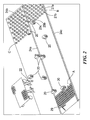
- Fig. 1 shows a typical container farm where seedlings are placed in containers in building 10. Later, the plants are moved to greenhouse 12 and then, during the growing season, to fields 14, 16 and the like where the containers are spaced in rows. Later, as the plants grow, the containers may be repositioned (re-spacing). At the end of the growing season, the containers may be brought back into greenhouse 12 and/or the plants sold.
- the Background section above delineates other typical nursery and greenhouse operations. The use of manual labor to accomplish these tasks is both costly and time consuming. And, as noted in the Background section above, attempts at automating these tasks have been met with limited success.
- autonomous robots 20, Fig. 2 transport plant containers from location A where the containers are "jammed” to location B where the containers are spaced apart in rows as shown.
- robots 20 can retrieve containers from offloading mechanism 22 and space the containers apart in rows as shown at location C.
- Boundary marker 24a in one example, denote the separation between two adjacent plots where containers are to be placed.
- Boundary marker 24b denotes the first row of each plot.
- Boundary marker 24c may denote the other side of a plot.
- the plot width is an input to the robot.
- the boundary markers include retro-reflective tape laid on the ground.
- the reflective tape could include non-reflective portions denoting distance and the robots could thereby keep track of the distance they have traveled.
- Other markings can be included in the boundary tape. Natural boundary markers may also be used since many growing operations often include boards, railroad ties, and other obstacles denoting the extent of each plot and/or plot borders.
- at least main boundary 24a is a part of the system and is a length of retro-reflective tape.
- Other boundary systems include magnetic strips, visible non-retroreflective tape, a signal emitting wire, passive RFID modules, and the like.
- Each robot 20, Fig. 3 typically includes boundary sensing subsystem 30 for detecting the boundaries and container detection subsystem 32 which typically detects containers ready for transport, already placed in a given plot, and being carried by the robot.
- Electronic controller 34 is responsive to the outputs of both boundary sensing subsystem 30 and container detection subsystem 32 and is configured to control robot drive subsystem 36 and container lift mechanism 38 based on certain robot behaviors as explained below. Controller 34 is also responsive to user interface 100.
- the controller typically includes one or more microprocessors or equivalent programmed as discussed below.
- the power supply 31 for all the subsystems typically includes one or more rechargeable batteries located in the rear of the robot.
- robot 20, Figs. 4A-4B includes chassis 40 with opposing side wheels 42a and 42b driven together or independently by two motors 44a and 44b and a drive train, not shown.
- Yoke 46 is rotatable with respect to chassis 40.
- Spaced forks 48a and 48b extend from yoke 46 and are configured to grasp a container. The spacing between forks 48a and 48b can be manually adjusted to accommodate containers of different diameters. In other examples, yoke 46 can accommodate two or even more containers at a time.
- Container shelf 47 is located beneath the container lifting forks to support the container during transport.
- a drive train is employed to rotate yoke 46, Figs. 5A-5B .
- gearbox 60a is driven by motor 62a.
- Driver sprocket 63a is attached to the output shaft of gearbox 60a and drives large sprocket 64a via belt or chain 65a.
- Large sprocket 64a is fixed to but rotates with respect to the robot chassis.
- Sprocket 66a rotates with sprocket 64a and, via belt or chain 67a, drives sprocket 68a rotatably disposed on yoke link 69a interconnecting sprockets 64a and 68a.
- Container fork 48a extends from link 71a attached to sprocket 68a.
- Figs. 4A , 4B , and 5A show that a similar drive train exists on the other side of the yoke. The result is a yoke which, depending on which direction motors 62a and 62b turn, extends and is lowered to retrieve a container on the ground and then raises and retracts to lift the container all the while keeping forks 48a and 48b and a container located therebetween horizontal.
- Figs. 4A-4B also show forward skid plate 70 typically made of plastic (e.g., UHMW PE) to assist in supporting the chassis.
- Boundary sensor modules 80a and 80b each include an infrared emitter and infrared detector pair.
- the container detection subsystem in this example includes linear array 88 of alternating infrared emitter and detection pairs, e.g., emitter 90 and detector 92. This subsystem is used to detect containers already placed to maneuver the robot accordingly to place a carried container properly. This subsystem is also used to maneuver the robot to retriever a container for replacement.
- the container detection subsystem typically also includes an infrared emitter detector pair 93 and 95 associated with fork 48a aimed at the other fork which includes reflective tape.
- container detection subsystem 32, Fig. 3 may include a subsystem for determining if a container is located between forks 48a and 48b, Figs. 4-5 .
- Controller 34, Fig. 3 is responsive to the output of this subsystem and may control drive subsystem 36, Fig. 3 according to one of several programmed behaviors.
- the robot returns to the location of beacon 29, Fig. 2 and attempts to retrieve another container. If the robot attempts to retrieve a container there but is unsuccessful, the robot may simply stop operating. In any case, the system helps ensure that if a container is present between forks 48a and 48b, Fig. 4 , controller 34 does not control the robot in a way that another container is attempted to be retrieved.
- controller 34, Fig. 3 is configured, (e.g., programmed) to include logic which functions as follows. Controller 34 is responsive to the output of boundary sensing subsystem 30 and the output of container detection subsystem 32. Controller 34 controls drive subsystem 36, (e.g., a motor 44, Fig. 4 for each wheel) to follow a boundary (e.g., boundary 24a, Fig. 2 ) once intercepted until a container is detected (e.g., container 25a, Fig. 2 in row 27a). Controller 34, Fig. 3 then commands drive subsystem 36 to turn to the right and maneuver in a row (e.g., row 27b, Fig.
- a boundary e.g., boundary 24a, Fig. 2
- a container in that row is detected (e.g., container 25b, Fig. 2 ).
- the robot then maneuvers and controller 34 commands lift mechanism 38, Fig. 3 to place container 25c (the present container carried by the robot) in row 27b, Fig. 2 proximate container 25b.
- Controller 34, Fig. 3 then controls drive subsystem 36 to maneuver the robot to a prescribed container source location (e.g., location A, Fig. 2 ).
- the system may include radio frequency or other (e.g., infrared) beacon transmitter 29 in which case robot 20, Fig. 3 would include a receiver 33 to assist robot 20 and returning to the container source location (may be based on signal strength). Dead reckoning, boundary following, and other techniques may be used to assist the robot in returning to the source of the containers.
- the robot includes a camera, the source of containers could be marked with a sign recognizable by the camera to denote the source of containers.
- controller 34 controls drive subsystem 36 and lift mechanism 38 to retrieve another container as shown in Fig. 2 .
- Fig. 6 depicts additional possible programming associated with controller 34, Fig. 3 .
- Fig. 6A shows how a robot is able to place the first container in the first row in a given plot.
- controller 34, Fig. 3 commands the robot to place container 27a proximate boundary 24c in the first row.
- boundaries 24a through 24c may be reflective tape as described above and/or obstructions typically associated with plots at the nursery site. Any boundary could also be virtual, (e.g., a programmed distance).
- the robot follows boundary 24a and arrives at boundary 24b and detects no container.
- Fig. 6 shows the robot turning 90° but the robot could be commanded to turn at the other angles to create other container patterns. Other condition/response algorithms are possible.
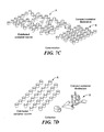
- distributed containers at source A, Fig. 7A can be "jammed" at location B; distributed containers at location A, Fig. 7B can be respaced at location B; distributed containers at location A, Fig. 7C can be consolidated at location B; and/or distributed containers at location A, Fig. 7D can be transported to location B for collection.
- Fig. 8 shows an example of a robot user interface 100 with input 102a for setting the desired bed width. This sets a virtual boundary, for example, boundary 24c, Fig. 2 .
- Input 102b allows the user to set the desired container spacing.
- Input 102c allows the user to set the desired spacing pattern.
- Input 102d allows the user to set the desired container diameter.
- the general positioning of features on the robot are shown in Fig. 4 discussed above.
- the boundary sensor enables the robot to follow the reference boundary; the container sensors locate containers relative to the robot.
- the preferred container lifter is a one-degree-of-freedom mechanism including forks that remain approximately parallel with the ground as they swing in an arc to lift the container. Two drive wheels propel the robot. The robots perform the spacing task as shown in Fig.
- the robot follows the boundary B.
- the robot's container sensor beams detect a container. This signifies that the robot must turn left so that it can place the container it carries in the adjacent row (indicated by the vertical dashed line).
- the robot typically travels along the dashed line using dead-reckoning.
- the robot detects a container ahead.
- the robot computes and determines the proper placement position for the container it carries and maneuvers to deposit the container there. Had there been no container at position 3, the robot would have traveled to position 4 to place its container.
- the user typically dials in the maximum length, b, of a row.
- the computation of the optimal placement point for a container combines dead-reckoning with the robot's observation of the positions of the already-spaced containers. Side looking detectors may be used for this purpose.
- a camera-based container detection system includes a camera and source of structured light mounted on the robot R, Fig. 10A .
- the field of view of the camera (FOV) intersects with a wedge of light (L) produced by a laser or other source.
- L wedge of light
- the only pixels illuminated in the camera image are those where the light wedge intersects an obstacle that is within the field of view of both camera and light source.
- the height of a pixel in the image codes for the range of the object.
- One novel aspect of the subject invention is the way in which ambient light is eliminated from the image even when the robot moves at high speed in full sun.
- the structured light container measurement system may be a camera-based system designed to measure the x-y position of containers within the field of view of a camera at a relatively short range.
- the system is largely unaffected by ambient light, is unaffected by robot speeds of up to two meter per second or more, and is very low in cost compared to more conventional systems.
- the field of view of a camera intersects a flat wedge of laser light, as shown in Fig. 10A .
- the camera points along the direction of robot travel but angled up; the laser wedge also points forward but tilts downward.
- the camera located at the origin, has a field of view of angle ⁇ .
- the camera is positioned such that the x-axis of the coordinate system is aligned with the lower edge of the camera's field of view.
- the laser (L) intersects the camera's field of view between x min and x max and makes an angle ⁇ with the x-axis.
- a cylindrical lens spreads the beam from the laser into a wedge coming out of the page.
- the camera is able to detect any object within the range x min to x max .
- the height of h' is measured.
- x max may be about 2m, ⁇ about 5 degrees, and ⁇ is, 40 degrees.
- ⁇ is determined by noting that h at x min must approximately match the height of the smallest container the system needs to see, e.g., 6".
- h ⁇ / f 0.008.
- the ratio of these two values of h'/f is about 181.
- the system can detect a difference of 1cm at its maximum range if the camera field of view is 40 degrees and the camera has at least 181 pixels in the vertical dimension. At distances of less than x max , changes of 1cm in range produce a greater than one pixel difference in the image.
- the container measurement system also employs a novel method to identify the structured light signal in the image.
- This system is low in cost because it requires minimal computation and storage can use a slow (30 Hz) low-resolution camera. Yet, it is able to deliver rapid, accurate container positioning at all light levels.
- the container measurement system uses triangulation and structured light to compute the range to a container.
- the key challenge in such a system is to identify pixels in the image that are illuminated by the structured laser light and reject pixels that are not.
- the traditional method for accomplishing this is frame differencing.
- the structured light source is turned on, and an image is recorded, the light source is turned off and a second image is recorded. Next, the second image is subtracted from the first on a pixel-by-pixel basis. If the only change between the two images is the presence of the structure light in the first then the only non-zero pixels in the difference correspond to structured light.
- Two drawbacks to the use of this method in a robot in accordance with the subject invention are as follows. First, the robots move rapidly and thus the constraint that nothing changes between images except the structured light is not satisfied. Second, the fact that two complete images must be stored and differenced adds storage and computation requirements thus increasing cost.
- the inventive container measuring system works as follows.
- the camera is turned to 90 degrees to its normal mounting position so that pixels normally exposed and read out in rows are read out as columns.
- the structured light (a plane of laser light) is synchronized to column exposure. That is, the laser is turned on, a row is exposed and read out, then the laser is turned off, and the adjacent row is exposed and read out, and so on.
- the detail in a typical image can be expected not to change very much from one column to the next.
- the laser-off column is subtracted from the adjacent laser-on column, the largest value in the difference will correspond to pixels illuminated by the laser.
- the robot will move two orders of magnitude less between the processing of two columns than it moves between the time two frames are processed.
- the robot may move significantly during the time required to process a frame one column at a time.
- the speed of the robot is known, it is possible to eliminate the resulting motion distortion from the data.
- the structured light system places no unusual demands on the camera.
- the camera's built-in facilities for automatic gain adjustment should enable it to operate under all light conditions. If rather than the column-differencing scheme described above, a conventional frame-differencing scheme were used to measure the containers, the standard the camera would have to meet to ensure that the difference between two images was almost entirely due to the modulation of the structured light source rather than the motion of other image features is explained as follows.
- an alternate strategy could attempt to detect objects when they are far away using a 30 Hz camera and slow the robot down before the object reaches x min .
- Focused light or an infrared source could be used.
- the container detection system can also be implemented using discrete components rather than a camera.
- a collection of IR ranging sensors (S) measures the distance from robot to container. Emitted beams (e) and detection paths (d) are shown.
- FIG. 12 A flowchart of the container centering/pickup method is shown in Fig. 12 .
- Fig. 13 depicts the steps the robot performs.
- step 120 the robot servos to within a fixed distance d
- the robot is accurately aligned for container pickup when angle ⁇ is zero.
- step 122 Fig. 12
- the robot extends the forks and drives forward while servoing to maintain alignment
- Fig. 13B the robot detects the container between its forks and stops its forward motion.
- Fig. 13D the robot retracts the forks by sweeping through an arc. This motion captures the container and moves it within the footprint of the robot.
- the preferred system of the subject invention minimizes cost by avoiding high-performance but expensive solutions in favor of lower cost systems that deliver only as much performance as required and only in the places that performance is necessary.
- navigation and container placement are not typically enabled using, for example a carrier phase differential global positioning system. Instead, a combination of boundary following, beacon following, and dead-reckoning techniques are used.
- the boundary subsystem of the subject invention provides an indication for the robot regarding where to place containers greatly simplifying the user interface.
- the boundary provides a fixed reference and the robot can position itself with high accuracy with respect to the boundary.
- the robot places containers within a few feet of the boundary. This arrangement affords little opportunity for dead-reckoning errors to build up when the robot turns away from the boundary on the way to placing a container.
- the robot After the container is deposited, the robot must return to collect the next container. Containers are typically delivered to the field by the wagonload. By the time one wagonload has been spaced, the next will have been delivered further down the field. In order to indicate the next load, the user may position a beacon near that load. The robot follows this procedure: when no beacon is visible, the robot uses dead-reckoning to travel as nearly as possible to the place it last picked up a container. If it finds a container there, it collects and places the container in the usual way. If the robot can see the beacon, it moves toward the beacon until it encounters a nearby container. In this way, the robot is able to achieve the global goal of spacing all the containers in the field, using only local knowledge and sensing. Relying only on local sensing makes the system more robust and lower in cost.
- the boundary markers show the robots where containers are to be placed.
- the beacon shows the robots where to pick up the containers.
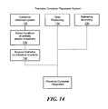
- Fig. 14 depicts how, in one example, the combination of container detection system 32, the detection of already placed containers (130), the use of Baysian statistics on container locations (132), dead reckoning (134), and boundary referencing (136) is used to precisely place containers carried by the robots.
- Fig. 15 shows a robot 20' with dual container lifting mechanisms 150a and 150b in accordance with the subject invention.
- the lifting mechanism or mechanisms are configured to transport objects other than containers for plants, for example, pumpkins and the like.
Landscapes
- Engineering & Computer Science (AREA)
- Mechanical Engineering (AREA)
- Transportation (AREA)
- Life Sciences & Earth Sciences (AREA)
- Power Engineering (AREA)
- Structural Engineering (AREA)
- Environmental Sciences (AREA)
- Sustainable Development (AREA)
- Sustainable Energy (AREA)
- Aviation & Aerospace Engineering (AREA)
- Radar, Positioning & Navigation (AREA)
- Remote Sensing (AREA)
- Physics & Mathematics (AREA)
- General Physics & Mathematics (AREA)
- Automation & Control Theory (AREA)
- Civil Engineering (AREA)
- Geology (AREA)
- Manipulator (AREA)
- Warehouses Or Storage Devices (AREA)
- Control Of Position, Course, Altitude, Or Attitude Of Moving Bodies (AREA)
Claims (24)
- Système adaptable de manipulation de conteneurs comprenant :un sous-système frontière comprenant au moins un marquer de frontière (24a) pour diriger le placement des conteneurs (25) ; etun ou plusieurs robots (20) comprenant chacun :un châssis (40),un mécanisme de levage de conteneur (38) mobile par rapport au châssis du robot (40) pour transporter au moins un conteneur (25),un sous-système d'entraînement (36) pour manoeuvrer le châssis (40),un sous-système de détection de frontière (30),un sous-système de détection de conteneur (32), etun contrôleur (34) réagissant au sous-système de détection de frontière (30) et au sous-système de détection de conteneur (32), et configuré pour :contrôler le sous-système d'entraînement (36) pour intercepter un marqueur de frontière (24a), puis suivre le marqueur de frontière (24a) jusqu'à ce qu'un conteneur (25a) soit détecté, puis tourner, et manoeuvrer jusqu'à ce qu'un autre conteneur (25b) soit détecté, etcontrôler le mécanisme de levage de conteneur (38) pour placer un conteneur transporté (25c) à proximité du deuxième conteneur détecté (25b).
- Système selon la revendication 1, dans lequel le contrôleur (34) est en outre configuré pour contrôler le sous-système d'entraînement (36) pour ramener le robot (20) vers un emplacement source de conteneur prescrit.
- Système selon la revendication 1, dans lequel le contrôleur (34) est en outre configuré pour contrôler le mécanisme de levage de conteneur (38) pour récupérer un autre conteneur (25) à l'emplacement source.
- Système selon la revendication 2, comprenant en outre une balise de transmission (29) située à l'emplacement source émettant un signal, et chaque robot (20) comprend en outre un récepteur (33) pour recevoir le signal de balise émis.
- Système selon la revendication 1, dans lequel le sous-système de frontière comprend un ruban réfléchissant.
- Système selon la revendication 5, dans lequel la bande réfléchissante comprend des parties non réfléchissantes désignant une distance.
- Système selon la revendication 5, dans lequel le sous-système de détection de frontière (30) comprend au moins un émetteur infrarouge et au moins un détecteur infrarouge.
- Système selon la revendication 1, dans lequel le sous-système de détection de conteneur (32) comprend un réseau linéaire d'émetteurs d'infrarouges (90) et de détecteurs d'infrarouges (92).
- Système selon la revendication 1, dans lequel le sous-système de détection de conteneur (32) comprend un système configuré pour détecter si un conteneur (25) est présent dans ledit système de levage de conteneur (38).
- Système selon la revendication 9, dans lequel ledit système comprend une source d'infrarouges (93) et un détecteur d'infrarouges (95).
- Système selon la revendication 1, dans lequel le sous-système d'entraînement (36) comprend une paire de roues motrices (42a, 42b), une de chaque côté du châssis (40).
- Système selon la revendication 1, dans lequel le mécanisme de levage de conteneur (38) comprend :un étrier rotatif (46),une paire de fourches espacées (48a, 48b) s'étendant depuis l'étrier (46) pour saisir un conteneur (25), etun train d'entraînement entraîné dans une direction pour faire pivoter l'étrier (46) pour simultanément étendre et abaisser les fourches (48a, 48b) et entraîné dans la direction opposée pour simultanément rétracter et abaisser les fourches (48a, 48b).
- Système selon la revendication 1, comprenant en outre une interface utilisateur (100) et le contrôleur (34) réagissant à l'interface utilisateur (100).
- Système selon la revendication 13, dans lequel l'interface utilisateur (100) comprend une entrée (102a) pour régler la largeur d'un lit.
- Système selon la revendication 13, dans lequel l'interface utilisateur (100) comprend une entrée (102b) pour régler un espacement de conteneur souhaité.
- Système selon la revendication 13, dans lequel l'interface utilisateur (100) comprend une entrée (102c) pour régler la configuration d'espacement souhaitée.
- Système selon la revendication 13, dans lequel l'interface utilisateur (100) comprend une entrée (102d) pour régler le diamètre de conteneur souhaité.
- Système selon la revendication 1, dans lequel le contrôleur (34) est en outre configuré pour détecter une condition de conteneur/frontière et pour faire fonctionner en réponse le sous-système d'entraînement (36) et le mécanisme de levage de conteneur (38) sur la base de la condition.
- Système selon la revendication 18, dans lequel une première condition est qu'aucun conteneur (25) n'est détecté avant que trois marqueurs de frontière (24a, 24b, 24c) ne soient détectés.
- Système selon la revendication 19, dans lequel une réponse à la première condition consiste à localiser le troisième marqueur de frontière (24c) ou une obstruction, et à placer un conteneur transporté (27a) à proximité du marqueur de frontière (24c) ou une obstruction pour placer le premier conteneur (27a) dans la première rangée.
- Système selon la revendication 18, dans lequel une deuxième condition est qu'aucun conteneur n'est détecté avant que deux marqueurs de frontière (24a, 24b) ne soient détectés.
- Système selon la revendication 21, dans lequel une réponse à la deuxième condition consiste à suivre le deuxième marqueur de frontière (24b), à détecter un conteneur (27a), et à placer un conteneur transporté (27b) à proximité du conteneur détecté (27a) pour remplir la première rangée de conteneurs.
- Système selon la revendication 18, dans lequel une troisième condition est qu'un premier marqueur de frontière (24a) est suivi, un conteneur (27d) est détecté, le robot (20) tourne, mais aucun autre conteneur n'est détecté avant qu'un deuxième marqueur de frontière (24c) ou qu'un obstacle soit détecté.
- Système selon la revendication 23, dans lequel une réponse à la troisième condition consiste à placer un conteneur transporté (27e) à proximité du deuxième marqueur de frontière (24c) ou d'une obstruction pour remplir une rangée avec son premier conteneur (27e).
Applications Claiming Priority (2)
| Application Number | Priority Date | Filing Date | Title |
|---|---|---|---|
| US6676808P | 2008-02-21 | 2008-02-21 | |
| PCT/US2009/001031 WO2009105211A2 (fr) | 2008-02-21 | 2009-02-19 | Système adaptable de manipulation de conteneur |
Publications (3)
| Publication Number | Publication Date |
|---|---|
| EP2244910A2 EP2244910A2 (fr) | 2010-11-03 |
| EP2244910A4 EP2244910A4 (fr) | 2013-05-15 |
| EP2244910B1 true EP2244910B1 (fr) | 2015-03-25 |
Family
ID=40986098
Family Applications (1)
| Application Number | Title | Priority Date | Filing Date |
|---|---|---|---|
| EP09711619.8A Not-in-force EP2244910B1 (fr) | 2008-02-21 | 2009-02-19 | Système adaptable de manipulation de conteneur |
Country Status (3)
| Country | Link |
|---|---|
| US (2) | US8915692B2 (fr) |
| EP (1) | EP2244910B1 (fr) |
| WO (1) | WO2009105211A2 (fr) |
Families Citing this family (36)
| Publication number | Priority date | Publication date | Assignee | Title |
|---|---|---|---|---|
| US20110301757A1 (en) * | 2008-02-21 | 2011-12-08 | Harvest Automation, Inc. | Adaptable container handling robot with boundary sensing subsystem |
| ES2398571B1 (es) * | 2011-05-14 | 2014-02-06 | Pieter Adriaan Laurens VAN SOEST | Sistema de dirección para uso de vehículos en carriles angostos |
| US9147173B2 (en) | 2011-10-31 | 2015-09-29 | Harvest Automation, Inc. | Methods and systems for automated transportation of items between variable endpoints |
| US8676425B2 (en) * | 2011-11-02 | 2014-03-18 | Harvest Automation, Inc. | Methods and systems for maintenance and other processing of container-grown plants using autonomous mobile robots |
| US8937410B2 (en) | 2012-01-17 | 2015-01-20 | Harvest Automation, Inc. | Emergency stop method and system for autonomous mobile robots |
| US9271446B2 (en) | 2012-06-28 | 2016-03-01 | Forage Innovations B.V. | Self-aligning apparatus and methods for gathering bales |
| JP6032972B2 (ja) * | 2012-06-29 | 2016-11-30 | 株式会社椿本チエイン | 移植装置及び移植方法 |
| US20140363264A1 (en) * | 2013-06-10 | 2014-12-11 | Harvest Automation, Inc. | Gripper assembly for autonomous mobile robots |
| GB2527574A (en) * | 2014-06-26 | 2015-12-30 | Kuhn Geldrop Bv | Pick-up device |
| US9415513B2 (en) | 2014-08-29 | 2016-08-16 | General Electric Company | Systems and methods for railyard robotics |
| US10471595B2 (en) | 2016-05-31 | 2019-11-12 | Ge Global Sourcing Llc | Systems and methods for control of robotic manipulation |
| GB2551802B (en) * | 2016-06-30 | 2021-10-13 | Growpura Ltd | A system and method of growing plants in the absence of soil |
| CA3107180C (fr) | 2016-09-06 | 2022-10-04 | Advanced Intelligent Systems Inc. | Poste de travail mobile destine a transporter une pluralite d'articles |
| US11046515B2 (en) * | 2017-08-03 | 2021-06-29 | Swarm Robotix Llc | Multi robot system and method for intermodal container transport |
| US11537107B2 (en) | 2017-10-09 | 2022-12-27 | Siemens Aktiengesellschaft | Autonomous mobile robots for movable production systems |
| EP3476211B1 (fr) * | 2017-10-09 | 2020-11-18 | Siemens Corporation | Robots mobiles autonomes pour des systèmes de production mobile |
| PL3495202T3 (pl) * | 2017-12-05 | 2021-02-08 | Guima Palfinger S.A.S. | System detekcji montowany na ciężarówce |
| WO2019157587A1 (fr) | 2018-02-15 | 2019-08-22 | Advanced Intelligent Systems Inc. | Appareil de support d'un article pendant le transport |
| JP6571832B1 (ja) * | 2018-05-01 | 2019-09-04 | 株式会社日本総合研究所 | 収容システム |
| JP7235853B2 (ja) * | 2018-08-30 | 2023-03-08 | キヤノンバージニア, インコーポレイテッド | 自律型監視システム |
| US10745219B2 (en) | 2018-09-28 | 2020-08-18 | Advanced Intelligent Systems Inc. | Manipulator apparatus, methods, and systems with at least one cable |
| US10751888B2 (en) | 2018-10-04 | 2020-08-25 | Advanced Intelligent Systems Inc. | Manipulator apparatus for operating on articles |
| US10810687B2 (en) | 2018-10-10 | 2020-10-20 | Advanced Intelligent Systems Inc. | Systems and methods for automated article transportation and management thereof |
| US10645882B1 (en) | 2018-10-29 | 2020-05-12 | Advanced Intelligent Systems Inc. | Method and apparatus for performing pruning operations using an autonomous vehicle |
| US10966374B2 (en) | 2018-10-29 | 2021-04-06 | Advanced Intelligent Systems Inc. | Method and apparatus for performing pruning operations using an autonomous vehicle |
| US10676279B1 (en) | 2018-11-20 | 2020-06-09 | Advanced Intelligent Systems Inc. | Systems, methods, and storage units for article transport and storage |
| US11827500B2 (en) | 2018-12-27 | 2023-11-28 | Toyota Research Institute, Inc. | Assistive robot systems for transporting containers |
| US11505017B2 (en) | 2018-12-27 | 2022-11-22 | Toyota Research Institute, Inc. | Devices including deployable hitch assemblies and autonomous engagement systems incorporating the same |
| US11148696B2 (en) | 2018-12-27 | 2021-10-19 | Toyota Research Institute, Inc. | Assistive robots including assemblies for accommodating obstacles and methods for using the same |
| US11420338B2 (en) | 2018-12-27 | 2022-08-23 | Toyota Research Institute, Inc. | Assistive robot systems for container tilting |
| WO2020185935A1 (fr) | 2019-03-14 | 2020-09-17 | Canon Virginia, Inc. | Système de chariot |
| JP6656462B2 (ja) * | 2019-11-01 | 2020-03-04 | 株式会社日本総合研究所 | 収容システム |
| SE545353C2 (en) | 2020-04-06 | 2023-07-18 | Husqvarna Ab | Adaptable operation for a robotic lawnmower |
| US20230210069A1 (en) * | 2021-12-30 | 2023-07-06 | Anthony Sunbeom KIM | Plant growth management system using movable flowerpot and control method using the same |
| CN115898051A (zh) * | 2022-11-18 | 2023-04-04 | 山东滨州城建集团有限公司 | 一种建筑工程用墙体砌筑装置 |
| US12557738B2 (en) | 2023-04-19 | 2026-02-24 | Pomme de Terre River Valley Products and Consulting, LLC | Agricultural vehicle |
Citations (1)
| Publication number | Priority date | Publication date | Assignee | Title |
|---|---|---|---|---|
| EP0774702A2 (fr) * | 1995-11-07 | 1997-05-21 | Friendly Machines Ltd. | Système de détection des lignes de démarcation pour un robot automatisé |
Family Cites Families (114)
| Publication number | Priority date | Publication date | Assignee | Title |
|---|---|---|---|---|
| US3913758A (en) * | 1973-06-15 | 1975-10-21 | Green Thumb Corp | Horticulture apparatus |
| US4065877A (en) * | 1976-11-12 | 1978-01-03 | Kelley Albert W | Container system for plant husbandry |
| US4217073A (en) * | 1978-05-05 | 1980-08-12 | Herman Miller, Inc. | Material handling system |
| FR2478596A1 (fr) * | 1980-03-19 | 1981-09-25 | Germaine Michel | Appareil pour saisir un a un des elements de tres faible taille |
| DE3136687C2 (de) * | 1981-09-16 | 1986-05-15 | Karl L. Dipl.-Ing. 7967 Bad Waldsee Ringer | System, Betriebsverfahren und Vorrichtungen zum gleichzeitigen und rangierfreien Umschlag zwischen Schiene und Schiene sowie Strasse und Schiene |
| US4476651A (en) * | 1983-01-27 | 1984-10-16 | Geoffrey Drury | Apparatus and method for transporting growing plants |
| US4700301A (en) * | 1983-11-02 | 1987-10-13 | Dyke Howard L | Method of automatically steering agricultural type vehicles |
| JPH0765908B2 (ja) | 1984-08-29 | 1995-07-19 | 株式会社前川製作所 | 斜交縞による回転軸間の相対変位角検出装置 |
| JPH0687203B2 (ja) | 1985-03-07 | 1994-11-02 | 日立機電工業株式会社 | 無人搬送車の誘導用光反射テープの読み取り装置 |
| CH668655A5 (de) | 1985-03-15 | 1989-01-13 | Jd Technologie Ag | Passivspur-einrichtung zur fuehrung und steuerung von fahrerlosen transport- und montageeinheiten. |
| IT1187347B (it) * | 1985-03-29 | 1987-12-23 | Decco Roda Spa | Macchina automatica per il prelievo da almeno una stazione di carico e l'accatastamento e/o il deposito su almeno una stazione di scarico di cassoni particolarmente di prodotti ortofrutticoli selezionati |
| US4793096A (en) * | 1986-02-20 | 1988-12-27 | Speedling Incorporated | Plant growing and handling system |
| US4869637A (en) * | 1986-08-27 | 1989-09-26 | Bud Antle, Inc. | Plant transfer mechanism |
| EP0302542B1 (fr) * | 1987-07-14 | 1994-01-26 | Koninklijke Philips Electronics N.V. | Dispositif pour transporter des supports à partir et en direction d'un dispositif de positionnement et dispositif sélecteur destiné à un dispositif |
| US5020965A (en) * | 1988-04-28 | 1991-06-04 | Kao Corporation | Method for shifting goods and apparatus therefor |
| US5046914A (en) * | 1988-07-12 | 1991-09-10 | Cybermation, Inc. | Parallel lifting device |
| JP2717810B2 (ja) * | 1988-08-16 | 1998-02-25 | 本田技研工業株式会社 | 自走型作業ロボット |
| DE3828447C2 (de) | 1988-08-22 | 1998-03-12 | Eisenmann Kg Maschbau | Optische Leitvorrichtung für fahrerlose Transportsysteme |
| AT392564B (de) * | 1989-03-31 | 1991-04-25 | Visser S Gravendeel Holding | Einrichtung zum versetzen von magazinierten jungpflanzen |
| US5051906A (en) * | 1989-06-07 | 1991-09-24 | Transitions Research Corporation | Mobile robot navigation employing retroreflective ceiling features |
| US5020964A (en) * | 1989-11-27 | 1991-06-04 | Ford Motor Company | Method and apparatus for robotic transfer of workpieces |
| US5016541A (en) * | 1989-12-14 | 1991-05-21 | Feaster Jr William L | Greenhouse transport system |
| US5081941A (en) * | 1990-03-27 | 1992-01-21 | Weeks Paul R | Apparatus for excavating and transplanting trees and the like |
| JP2507896B2 (ja) | 1990-03-31 | 1996-06-19 | 東北農業試験場長 | 苗箱配置・積込み装置 |
| JPH0747403B2 (ja) * | 1990-05-22 | 1995-05-24 | インベストロニカ・ソシエダッド・アノニマ | プログラム制御による箱、コンテナ等の操作・移送装置 |
| US5403142A (en) * | 1991-08-22 | 1995-04-04 | Stewart-Glapat Corporation | Pallet handling adjustable conveyor |
| US5348361A (en) * | 1991-09-27 | 1994-09-20 | John Ilchuk | Tree mover |
| JP2589901B2 (ja) * | 1991-11-26 | 1997-03-12 | インターナショナル・ビジネス・マシーンズ・コーポレイション | 能動型センサを備えた移動機械 |
| US5348063A (en) * | 1993-01-04 | 1994-09-20 | Semi-Bulk Systems, Inc. | Material handling system |
| US5442552A (en) | 1993-03-16 | 1995-08-15 | The Regents Of The University Of California | Robotic cultivator |
| NL9301982A (nl) * | 1993-11-16 | 1995-06-16 | Robert Marie Lubbers | Werkwijze voor het transporteren van een container en transportmiddelen voor het uitvoeren van de werkwijze. |
| US5496143A (en) * | 1994-04-11 | 1996-03-05 | Breyer; Stephen R. | Tree and shrub lifting system |
| DE69514316T2 (de) * | 1994-11-17 | 2001-01-04 | Kanzaki Kokyukoki Mfg. Co., Ltd. | Pflanzmaschine |
| IL113913A (en) * | 1995-05-30 | 2000-02-29 | Friendly Machines Ltd | Navigation method and system |
| JPH08335112A (ja) * | 1995-06-08 | 1996-12-17 | Minolta Co Ltd | 移動作業ロボットシステム |
| US5688102A (en) * | 1996-07-19 | 1997-11-18 | Vieselmeyer; Lee R. | Tree moving and planting apparatus |
| US5819863A (en) * | 1996-08-28 | 1998-10-13 | Lockheed Martin Idaho Technologies Company | Vehicle for carrying an object of interest |
| US5974348A (en) * | 1996-12-13 | 1999-10-26 | Rocks; James K. | System and method for performing mobile robotic work operations |
| AU7110698A (en) * | 1997-04-16 | 1998-11-11 | Carnegie Wave Energy Limited | Agricultural harvester with robotic control |
| US5988971A (en) * | 1997-07-09 | 1999-11-23 | Ade Optical Systems Corporation | Wafer transfer robot |
| JPH1177579A (ja) | 1997-09-03 | 1999-03-23 | Fanuc Ltd | ロボット非常停止用スイッチ機構並びに該機構を設けた教示操作盤 |
| US6532404B2 (en) * | 1997-11-27 | 2003-03-11 | Colens Andre | Mobile robots and their control system |
| EP1049964B1 (fr) * | 1997-11-27 | 2002-03-13 | Solar & Robotics | Ameliorations a des robots mobiles et a leur systeme de commande |
| US6186730B1 (en) * | 1998-01-12 | 2001-02-13 | Justin Place | Apparatus and method for loading agricultural material |
| IL124413A (en) | 1998-05-11 | 2001-05-20 | Friendly Robotics Ltd | System and method for area coverage with an autonomous robot |
| US6543983B1 (en) * | 1998-07-07 | 2003-04-08 | University Of Virginia Patent Foundation | Robotic pick up and deliver system |
| US6164537A (en) * | 1998-07-14 | 2000-12-26 | Klehm Ornamentals, Llc | Plant inventory, distribution and display system |
| US6212821B1 (en) * | 1999-05-10 | 2001-04-10 | Kieran L. Adam | Automatic plant selector |
| US6611738B2 (en) * | 1999-07-12 | 2003-08-26 | Bryan J. Ruffner | Multifunctional mobile appliance |
| US20020182046A1 (en) | 1999-07-23 | 2002-12-05 | Hagen Schempf | Robotic systems for handling objects |
| US20050135912A1 (en) * | 1999-07-23 | 2005-06-23 | Hagen Schempf | Robotic systems for handling objects |
| US6216631B1 (en) * | 1999-08-12 | 2001-04-17 | The Mitre Corporation | Robotic manipulation system utilizing patterned granular motion |
| US6243987B1 (en) * | 1999-09-01 | 2001-06-12 | Organitech Ltd. | Self contained fully automated robotic crop production facility |
| US6374155B1 (en) * | 1999-11-24 | 2002-04-16 | Personal Robotics, Inc. | Autonomous multi-platform robot system |
| DE10001078C1 (de) * | 2000-01-13 | 2001-05-17 | Dieter Opitz | Vorrichtung zum Verpflanzen von Bäumen oder Sträuchern |
| US6658324B2 (en) * | 2000-09-29 | 2003-12-02 | Gpc Biotech Ag | Pick and place robot system |
| WO2002052920A2 (fr) * | 2001-01-05 | 2002-07-11 | Pro Ag Designs Inc. | Empileuse de balles de foin |
| US6915607B2 (en) * | 2001-06-08 | 2005-07-12 | Tagawa Greenhouses, Inc. | Operational system for transplanting growing plants |
| US6690134B1 (en) * | 2001-01-24 | 2004-02-10 | Irobot Corporation | Method and system for robot localization and confinement |
| US6481948B2 (en) * | 2001-02-20 | 2002-11-19 | Lonnie K. Spears | System for adapting and mounting industrial and agricultural work implements to a pickup truck |
| AUPR340301A0 (en) | 2001-02-27 | 2001-03-22 | P & G Developments Pty Ltd | Material handling system & method |
| US6726431B2 (en) * | 2001-04-09 | 2004-04-27 | Jay C. Morrell | Container handling system and method |
| US6763282B2 (en) * | 2001-06-04 | 2004-07-13 | Time Domain Corp. | Method and system for controlling a robot |
| US6638004B2 (en) * | 2001-07-13 | 2003-10-28 | Tru-Si Technologies, Inc. | Article holders and article positioning methods |
| US6667592B2 (en) * | 2001-08-13 | 2003-12-23 | Intellibot, L.L.C. | Mapped robot system |
| EP1436199A1 (fr) * | 2001-10-19 | 2004-07-14 | MonoGen, Inc. | Appareil et procede de scellement d'une fiole d'echantillon |
| NL1019257C2 (nl) * | 2001-10-30 | 2003-05-02 | Rijnplant Bv | Werkwijze voor het in een kas op een eerste laag niveau aangebrachte drager kweken van in houders opgenomen gewassen. |
| NL1019537C2 (nl) * | 2001-12-11 | 2003-06-17 | Visser S Gravendeel Holding | Inrichting en werkwijze voor het verplaatsen, uiteenzetten en bijeenzetten van voorwerpen. |
| CA2475546A1 (fr) * | 2002-02-08 | 2003-08-14 | John K. Chapin | Procede et appareil pour guider le deplacement d'un animal en liberte par stimulation du cerveau |
| US6857493B2 (en) * | 2002-02-13 | 2005-02-22 | Paragon Technologies, Inc. | Automatic load positioning for a conveyor cart |
| US6729836B2 (en) * | 2002-03-13 | 2004-05-04 | Stingel, Iii Frederick J. | Automated container storage and delivery system |
| US7184855B2 (en) * | 2002-03-13 | 2007-02-27 | Stingel Iii Frederick J | Automated container storage and delivery system |
| US6950722B2 (en) * | 2002-07-15 | 2005-09-27 | Distrobot Systems, Inc. | Material handling system and method using mobile autonomous inventory trays and peer-to-peer communications |
| US6904335B2 (en) | 2002-08-21 | 2005-06-07 | Neal Solomon | System, method and apparatus for organizing groups of self-configurable mobile robotic agents in a multi-robotic system |
| ES2300420T3 (es) * | 2002-12-23 | 2008-06-16 | Cropdesign N.V. | Sistema automatizado para la manipulacion de recipientes que contienen plantas. |
| KR100506533B1 (ko) * | 2003-01-11 | 2005-08-05 | 삼성전자주식회사 | 이동로봇 및 그에 따른 자율주행 시스템 및 방법 |
| US7086820B1 (en) * | 2003-03-17 | 2006-08-08 | Blake Daniel T | Apparatus for the lifting and placement of loads |
| EP1620748A1 (fr) * | 2003-04-22 | 2006-02-01 | Koninklijke Philips Electronics N.V. | Systeme, appareil et procede pour estimer la position d'un objet |
| JP4284611B2 (ja) * | 2003-07-11 | 2009-06-24 | 株式会社ダイフク | 搬送装置 |
| DE10348884A1 (de) | 2003-10-14 | 2005-05-25 | Pilz Gmbh & Co. Kg | Sicherheitsschalter, insbesondere Not-Aus-Schalter, zum sicheren Abschalten eines gefahrbringenden Gerätes |
| AR046430A1 (es) | 2003-10-28 | 2005-12-07 | Cargill Inc | Sistema de manipulacion de productos agricolas. |
| US7765780B2 (en) | 2003-12-12 | 2010-08-03 | Vision Robotics Corporation | Agricultural robot system and method |
| US7854108B2 (en) * | 2003-12-12 | 2010-12-21 | Vision Robotics Corporation | Agricultural robot system and method |
| US7400108B2 (en) * | 2004-04-15 | 2008-07-15 | University Of Utah Research Foundation | System and method for controlling modular robots |
| AU2004201709A1 (en) * | 2004-04-23 | 2005-11-10 | Foodmach Pty Ltd | Materials handling system |
| US20050238465A1 (en) * | 2004-04-27 | 2005-10-27 | Razumov Sergey N | Robotic retail facility |
| US20050254927A1 (en) * | 2004-05-17 | 2005-11-17 | James Swetman | Portable transporting apparatus |
| US6988518B2 (en) * | 2004-06-02 | 2006-01-24 | Automation Techniques, Inc. | Robotic system and method for transport of materials with minimization of footprint size |
| US7198312B2 (en) * | 2004-06-29 | 2007-04-03 | Blaho Milan D | Arrangement for handling objects such as nursery stock or the like |
| JP2006035397A (ja) * | 2004-07-29 | 2006-02-09 | Fanuc Ltd | 搬送ロボットシステム |
| US20060045679A1 (en) * | 2004-08-16 | 2006-03-02 | Eric Ostendorff | Robotic retrieval apparatus |
| KR100690669B1 (ko) * | 2005-05-17 | 2007-03-09 | 엘지전자 주식회사 | 자율 주행 로봇의 위치인식 시스템 |
| JP4300199B2 (ja) | 2005-06-13 | 2009-07-22 | 株式会社東芝 | 移動ロボット、移動ロボットの位置姿勢算出方法、移動ロボットの自律走行システム |
| WO2007004551A1 (fr) | 2005-07-01 | 2007-01-11 | Rorze Corporation | Appareil de transport de contenants et systeme de transport de contenants |
| US7610122B2 (en) * | 2005-08-16 | 2009-10-27 | Deere & Company | Mobile station for an unmanned vehicle |
| US7559736B1 (en) | 2005-09-08 | 2009-07-14 | Thomas Streett Mohan | Apparatus and method for efficiently loading and unloading racks of potted plants in a wholesale nursery where the plants are growing |
| US9026301B2 (en) | 2005-10-14 | 2015-05-05 | Aethon, Inc. | Robotic ordering and delivery system software and methods |
| SE529377C2 (sv) | 2005-10-18 | 2007-07-24 | Morphic Technologies Ab Publ | Metod och arrangemang för att lokalisera och plocka upp föremål från en bärare |
| JP4456561B2 (ja) | 2005-12-12 | 2010-04-28 | 本田技研工業株式会社 | 自律移動ロボット |
| US20070140821A1 (en) | 2005-12-19 | 2007-06-21 | Betzalel Robotics, Llc | Autonomous load/unload robot |
| US8050863B2 (en) | 2006-03-16 | 2011-11-01 | Gray & Company, Inc. | Navigation and control system for autonomous vehicles |
| US20080046130A1 (en) | 2006-08-03 | 2008-02-21 | Deere & Company, A Delaware Corporation | Agricultural automation system with field robot |
| WO2008025016A2 (fr) | 2006-08-25 | 2008-02-28 | The Trustees Of Columbia University In The City Of New York | systèmes et procédés de biodosimétrie à RAYONNEMENT à invasion minime, à haut rendement |
| US7735626B2 (en) | 2006-11-13 | 2010-06-15 | Pioneer Hi-Bred International, Inc. | Apparatus, method and system for handling, positioning, and/or automatically orienting objects |
| US7815411B2 (en) | 2007-05-11 | 2010-10-19 | Larry Alexander | Multiple function landscaping system and method |
| JP5047709B2 (ja) | 2007-07-04 | 2012-10-10 | 株式会社日立製作所 | 移動装置、システム、移動方法及び移動プログラム |
| JP5037248B2 (ja) | 2007-07-17 | 2012-09-26 | 株式会社日立製作所 | 情報収集システムおよび情報収集ロボット |
| DE102007039850B4 (de) | 2007-08-23 | 2016-09-15 | Khs Gmbh | Packerkopf |
| JP4516592B2 (ja) | 2007-12-06 | 2010-08-04 | 本田技研工業株式会社 | 移動型ロボット |
| JP4251580B1 (ja) | 2008-01-08 | 2009-04-08 | Tdk株式会社 | 被収容物搬送システム |
| WO2009123650A1 (fr) | 2008-04-02 | 2009-10-08 | Irobot Corporation | Systèmes robotiques |
| BRPI0905641A2 (pt) | 2009-07-08 | 2011-03-29 | Basf Se | sistema para diagnóstico de anomalias de plantas |
| US20110025454A1 (en) | 2009-07-30 | 2011-02-03 | Itzhak Pomerantz | Emergency machine stopping method and system |
| CN104508582B (zh) | 2012-05-29 | 2018-02-16 | 柯马有限责任公司 | 自动导引搬运车的使用方法 |
-
2009
- 2009-02-18 US US12/378,612 patent/US8915692B2/en active Active
- 2009-02-19 WO PCT/US2009/001031 patent/WO2009105211A2/fr not_active Ceased
- 2009-02-19 EP EP09711619.8A patent/EP2244910B1/fr not_active Not-in-force
-
2014
- 2014-11-21 US US14/550,232 patent/US20150151933A1/en not_active Abandoned
Patent Citations (1)
| Publication number | Priority date | Publication date | Assignee | Title |
|---|---|---|---|---|
| EP0774702A2 (fr) * | 1995-11-07 | 1997-05-21 | Friendly Machines Ltd. | Système de détection des lignes de démarcation pour un robot automatisé |
Also Published As
| Publication number | Publication date |
|---|---|
| WO2009105211A3 (fr) | 2009-12-30 |
| EP2244910A4 (fr) | 2013-05-15 |
| EP2244910A2 (fr) | 2010-11-03 |
| WO2009105211A2 (fr) | 2009-08-27 |
| US20090214324A1 (en) | 2009-08-27 |
| US20150151933A1 (en) | 2015-06-04 |
| US8915692B2 (en) | 2014-12-23 |
Similar Documents
| Publication | Publication Date | Title |
|---|---|---|
| EP2244910B1 (fr) | Système adaptable de manipulation de conteneur | |
| US20110301757A1 (en) | Adaptable container handling robot with boundary sensing subsystem | |
| US12275589B2 (en) | Material handling system | |
| US11726497B2 (en) | Control method for cleaning system | |
| US12158759B2 (en) | Docking method | |
| EP0829040B1 (fr) | Procede et systeme de navigation | |
| US5974348A (en) | System and method for performing mobile robotic work operations | |
| US10459443B2 (en) | Semi-autonomous farm transport vehicle for picked produce | |
| EP2583147B1 (fr) | Procédé et appareil permettant de gérer et de contrôler des véhicules industriels pilotés et automatiques | |
| US8676425B2 (en) | Methods and systems for maintenance and other processing of container-grown plants using autonomous mobile robots | |
| DK178276B1 (en) | Method for recording and predicting position data for a selfpropelled wheeled vehicle, and delivery or pick up system comprising a self-propelled, self-guided wheeled vehicle | |
| US11480953B2 (en) | Autonomous broadcasting system for self-driving vehicle | |
| JP6766801B2 (ja) | 作業車両 | |
| CN105607635A (zh) | 自动导引车全景光学视觉导航控制系统及全向自动导引车 | |
| CN111674800B (zh) | 用于自动驾驶系统的智能仓储技术 | |
| CN102393742A (zh) | 一种设施农业用轮式智能运输车 | |
| EP4075944B1 (fr) | Chariot d'horticulture bidirectionnel à détection primaire grossière et détection secondaire fine de parties extrémité de tête de rails | |
| US20200183397A1 (en) | Method for handling goods | |
| CN108502434A (zh) | 托盘机器人 | |
| WO2023222855A1 (fr) | Système et procédé d'assistance robotique autonome dans des tâches agricoles | |
| JP2025142939A (ja) | 作業車両 | |
| JP2023066448A (ja) | 農作業用台車の自動運転システム及び農作業用台車 | |
| KR20260000374A (ko) | 배추 예취 및 배추 수집을 위한 협동로봇 | |
| CN117902254A (zh) | 一种室内立体种植配套绳牵引搬运系统 | |
| Dias et al. | Trident Sensing System: A Configuration of Sensors To Aid Alignment of An Intelligent Grasping Device Used for Field-Container Handling |
Legal Events
| Date | Code | Title | Description |
|---|---|---|---|
| PUAI | Public reference made under article 153(3) epc to a published international application that has entered the european phase |
Free format text: ORIGINAL CODE: 0009012 |
|
| 17P | Request for examination filed |
Effective date: 20100817 |
|
| AK | Designated contracting states |
Kind code of ref document: A2 Designated state(s): AT BE BG CH CY CZ DE DK EE ES FI FR GB GR HR HU IE IS IT LI LT LU LV MC MK MT NL NO PL PT RO SE SI SK TR |
|
| AX | Request for extension of the european patent |
Extension state: AL BA RS |
|
| RIC1 | Information provided on ipc code assigned before grant |
Ipc: B66F 1/00 20060101AFI20101208BHEP |
|
| DAX | Request for extension of the european patent (deleted) | ||
| RAP1 | Party data changed (applicant data changed or rights of an application transferred) |
Owner name: HARVEST AUTOMATION, INC. |
|
| A4 | Supplementary search report drawn up and despatched |
Effective date: 20130411 |
|
| RIC1 | Information provided on ipc code assigned before grant |
Ipc: B66F 1/00 20060101AFI20130405BHEP |
|
| 17Q | First examination report despatched |
Effective date: 20131104 |
|
| REG | Reference to a national code |
Ref country code: DE Ref legal event code: R079 Ref document number: 602009030167 Country of ref document: DE Free format text: PREVIOUS MAIN CLASS: B66F0001000000 Ipc: A01G0009080000 |
|
| GRAP | Despatch of communication of intention to grant a patent |
Free format text: ORIGINAL CODE: EPIDOSNIGR1 |
|
| RIC1 | Information provided on ipc code assigned before grant |
Ipc: B60L 11/18 20060101ALI20141027BHEP Ipc: A01G 9/08 20060101AFI20141027BHEP Ipc: A01G 9/14 20060101ALI20141027BHEP |
|
| INTG | Intention to grant announced |
Effective date: 20141114 |
|
| GRAS | Grant fee paid |
Free format text: ORIGINAL CODE: EPIDOSNIGR3 |
|
| GRAA | (expected) grant |
Free format text: ORIGINAL CODE: 0009210 |
|
| AK | Designated contracting states |
Kind code of ref document: B1 Designated state(s): AT BE BG CH CY CZ DE DK EE ES FI FR GB GR HR HU IE IS IT LI LT LU LV MC MK MT NL NO PL PT RO SE SI SK TR |
|
| REG | Reference to a national code |
Ref country code: GB Ref legal event code: FG4D |
|
| REG | Reference to a national code |
Ref country code: CH Ref legal event code: EP |
|
| REG | Reference to a national code |
Ref country code: IE Ref legal event code: FG4D |
|
| REG | Reference to a national code |
Ref country code: DE Ref legal event code: R096 Ref document number: 602009030167 Country of ref document: DE Effective date: 20150507 |
|
| REG | Reference to a national code |
Ref country code: AT Ref legal event code: REF Ref document number: 717276 Country of ref document: AT Kind code of ref document: T Effective date: 20150515 |
|
| REG | Reference to a national code |
Ref country code: NL Ref legal event code: T3 |
|
| PG25 | Lapsed in a contracting state [announced via postgrant information from national office to epo] |
Ref country code: LT Free format text: LAPSE BECAUSE OF FAILURE TO SUBMIT A TRANSLATION OF THE DESCRIPTION OR TO PAY THE FEE WITHIN THE PRESCRIBED TIME-LIMIT Effective date: 20150325 Ref country code: SE Free format text: LAPSE BECAUSE OF FAILURE TO SUBMIT A TRANSLATION OF THE DESCRIPTION OR TO PAY THE FEE WITHIN THE PRESCRIBED TIME-LIMIT Effective date: 20150325 Ref country code: HR Free format text: LAPSE BECAUSE OF FAILURE TO SUBMIT A TRANSLATION OF THE DESCRIPTION OR TO PAY THE FEE WITHIN THE PRESCRIBED TIME-LIMIT Effective date: 20150325 Ref country code: FI Free format text: LAPSE BECAUSE OF FAILURE TO SUBMIT A TRANSLATION OF THE DESCRIPTION OR TO PAY THE FEE WITHIN THE PRESCRIBED TIME-LIMIT Effective date: 20150325 |
|
| REG | Reference to a national code |
Ref country code: AT Ref legal event code: MK05 Ref document number: 717276 Country of ref document: AT Kind code of ref document: T Effective date: 20150325 |
|
| REG | Reference to a national code |
Ref country code: LT Ref legal event code: MG4D |
|
| PG25 | Lapsed in a contracting state [announced via postgrant information from national office to epo] |
Ref country code: LV Free format text: LAPSE BECAUSE OF FAILURE TO SUBMIT A TRANSLATION OF THE DESCRIPTION OR TO PAY THE FEE WITHIN THE PRESCRIBED TIME-LIMIT Effective date: 20150325 Ref country code: GR Free format text: LAPSE BECAUSE OF FAILURE TO SUBMIT A TRANSLATION OF THE DESCRIPTION OR TO PAY THE FEE WITHIN THE PRESCRIBED TIME-LIMIT Effective date: 20150626 |
|
| PG25 | Lapsed in a contracting state [announced via postgrant information from national office to epo] |
Ref country code: EE Free format text: LAPSE BECAUSE OF FAILURE TO SUBMIT A TRANSLATION OF THE DESCRIPTION OR TO PAY THE FEE WITHIN THE PRESCRIBED TIME-LIMIT Effective date: 20150325 Ref country code: RO Free format text: LAPSE BECAUSE OF FAILURE TO SUBMIT A TRANSLATION OF THE DESCRIPTION OR TO PAY THE FEE WITHIN THE PRESCRIBED TIME-LIMIT Effective date: 20150325 Ref country code: CZ Free format text: LAPSE BECAUSE OF FAILURE TO SUBMIT A TRANSLATION OF THE DESCRIPTION OR TO PAY THE FEE WITHIN THE PRESCRIBED TIME-LIMIT Effective date: 20150325 Ref country code: PT Free format text: LAPSE BECAUSE OF FAILURE TO SUBMIT A TRANSLATION OF THE DESCRIPTION OR TO PAY THE FEE WITHIN THE PRESCRIBED TIME-LIMIT Effective date: 20150727 Ref country code: SK Free format text: LAPSE BECAUSE OF FAILURE TO SUBMIT A TRANSLATION OF THE DESCRIPTION OR TO PAY THE FEE WITHIN THE PRESCRIBED TIME-LIMIT Effective date: 20150325 Ref country code: ES Free format text: LAPSE BECAUSE OF FAILURE TO SUBMIT A TRANSLATION OF THE DESCRIPTION OR TO PAY THE FEE WITHIN THE PRESCRIBED TIME-LIMIT Effective date: 20150325 |
|
| PG25 | Lapsed in a contracting state [announced via postgrant information from national office to epo] |
Ref country code: PL Free format text: LAPSE BECAUSE OF FAILURE TO SUBMIT A TRANSLATION OF THE DESCRIPTION OR TO PAY THE FEE WITHIN THE PRESCRIBED TIME-LIMIT Effective date: 20150325 Ref country code: AT Free format text: LAPSE BECAUSE OF FAILURE TO SUBMIT A TRANSLATION OF THE DESCRIPTION OR TO PAY THE FEE WITHIN THE PRESCRIBED TIME-LIMIT Effective date: 20150325 Ref country code: IS Free format text: LAPSE BECAUSE OF FAILURE TO SUBMIT A TRANSLATION OF THE DESCRIPTION OR TO PAY THE FEE WITHIN THE PRESCRIBED TIME-LIMIT Effective date: 20150725 |
|
| REG | Reference to a national code |
Ref country code: DE Ref legal event code: R097 Ref document number: 602009030167 Country of ref document: DE |
|
| PG25 | Lapsed in a contracting state [announced via postgrant information from national office to epo] |
Ref country code: DK Free format text: LAPSE BECAUSE OF FAILURE TO SUBMIT A TRANSLATION OF THE DESCRIPTION OR TO PAY THE FEE WITHIN THE PRESCRIBED TIME-LIMIT Effective date: 20150325 |
|
| PLBE | No opposition filed within time limit |
Free format text: ORIGINAL CODE: 0009261 |
|
| STAA | Information on the status of an ep patent application or granted ep patent |
Free format text: STATUS: NO OPPOSITION FILED WITHIN TIME LIMIT |
|
| 26N | No opposition filed |
Effective date: 20160105 |
|
| PG25 | Lapsed in a contracting state [announced via postgrant information from national office to epo] |
Ref country code: IT Free format text: LAPSE BECAUSE OF FAILURE TO SUBMIT A TRANSLATION OF THE DESCRIPTION OR TO PAY THE FEE WITHIN THE PRESCRIBED TIME-LIMIT Effective date: 20150325 |
|
| PGFP | Annual fee paid to national office [announced via postgrant information from national office to epo] |
Ref country code: DE Payment date: 20160216 Year of fee payment: 8 |
|
| PG25 | Lapsed in a contracting state [announced via postgrant information from national office to epo] |
Ref country code: SI Free format text: LAPSE BECAUSE OF FAILURE TO SUBMIT A TRANSLATION OF THE DESCRIPTION OR TO PAY THE FEE WITHIN THE PRESCRIBED TIME-LIMIT Effective date: 20150325 Ref country code: BE Free format text: LAPSE BECAUSE OF NON-PAYMENT OF DUE FEES Effective date: 20160229 |
|
| PGFP | Annual fee paid to national office [announced via postgrant information from national office to epo] |
Ref country code: NL Payment date: 20160210 Year of fee payment: 8 |
|
| PG25 | Lapsed in a contracting state [announced via postgrant information from national office to epo] |
Ref country code: BE Free format text: LAPSE BECAUSE OF FAILURE TO SUBMIT A TRANSLATION OF THE DESCRIPTION OR TO PAY THE FEE WITHIN THE PRESCRIBED TIME-LIMIT Effective date: 20150325 |
|
| PG25 | Lapsed in a contracting state [announced via postgrant information from national office to epo] |
Ref country code: MC Free format text: LAPSE BECAUSE OF FAILURE TO SUBMIT A TRANSLATION OF THE DESCRIPTION OR TO PAY THE FEE WITHIN THE PRESCRIBED TIME-LIMIT Effective date: 20150325 Ref country code: LU Free format text: LAPSE BECAUSE OF FAILURE TO SUBMIT A TRANSLATION OF THE DESCRIPTION OR TO PAY THE FEE WITHIN THE PRESCRIBED TIME-LIMIT Effective date: 20160219 |
|
| REG | Reference to a national code |
Ref country code: CH Ref legal event code: PL |
|
| GBPC | Gb: european patent ceased through non-payment of renewal fee |
Effective date: 20160219 |
|
| PG25 | Lapsed in a contracting state [announced via postgrant information from national office to epo] |
Ref country code: CH Free format text: LAPSE BECAUSE OF NON-PAYMENT OF DUE FEES Effective date: 20160229 Ref country code: LI Free format text: LAPSE BECAUSE OF NON-PAYMENT OF DUE FEES Effective date: 20160229 |
|
| REG | Reference to a national code |
Ref country code: FR Ref legal event code: ST Effective date: 20161028 |
|
| REG | Reference to a national code |
Ref country code: IE Ref legal event code: MM4A |
|
| PG25 | Lapsed in a contracting state [announced via postgrant information from national office to epo] |
Ref country code: GB Free format text: LAPSE BECAUSE OF NON-PAYMENT OF DUE FEES Effective date: 20160219 Ref country code: FR Free format text: LAPSE BECAUSE OF NON-PAYMENT OF DUE FEES Effective date: 20160229 Ref country code: IE Free format text: LAPSE BECAUSE OF NON-PAYMENT OF DUE FEES Effective date: 20160219 |
|
| PG25 | Lapsed in a contracting state [announced via postgrant information from national office to epo] |
Ref country code: MT Free format text: LAPSE BECAUSE OF FAILURE TO SUBMIT A TRANSLATION OF THE DESCRIPTION OR TO PAY THE FEE WITHIN THE PRESCRIBED TIME-LIMIT Effective date: 20150325 |
|
| REG | Reference to a national code |
Ref country code: DE Ref legal event code: R119 Ref document number: 602009030167 Country of ref document: DE |
|
| REG | Reference to a national code |
Ref country code: NL Ref legal event code: MM Effective date: 20170301 |
|
| PG25 | Lapsed in a contracting state [announced via postgrant information from national office to epo] |
Ref country code: NL Free format text: LAPSE BECAUSE OF NON-PAYMENT OF DUE FEES Effective date: 20170301 |
|
| PG25 | Lapsed in a contracting state [announced via postgrant information from national office to epo] |
Ref country code: DE Free format text: LAPSE BECAUSE OF NON-PAYMENT OF DUE FEES Effective date: 20170901 |
|
| PG25 | Lapsed in a contracting state [announced via postgrant information from national office to epo] |
Ref country code: CY Free format text: LAPSE BECAUSE OF FAILURE TO SUBMIT A TRANSLATION OF THE DESCRIPTION OR TO PAY THE FEE WITHIN THE PRESCRIBED TIME-LIMIT Effective date: 20150325 Ref country code: HU Free format text: LAPSE BECAUSE OF FAILURE TO SUBMIT A TRANSLATION OF THE DESCRIPTION OR TO PAY THE FEE WITHIN THE PRESCRIBED TIME-LIMIT; INVALID AB INITIO Effective date: 20090219 |
|
| PG25 | Lapsed in a contracting state [announced via postgrant information from national office to epo] |
Ref country code: NO Free format text: LAPSE BECAUSE OF NON-PAYMENT OF DUE FEES Effective date: 20150625 Ref country code: MK Free format text: LAPSE BECAUSE OF FAILURE TO SUBMIT A TRANSLATION OF THE DESCRIPTION OR TO PAY THE FEE WITHIN THE PRESCRIBED TIME-LIMIT Effective date: 20150325 Ref country code: TR Free format text: LAPSE BECAUSE OF FAILURE TO SUBMIT A TRANSLATION OF THE DESCRIPTION OR TO PAY THE FEE WITHIN THE PRESCRIBED TIME-LIMIT Effective date: 20150325 Ref country code: MT Free format text: LAPSE BECAUSE OF FAILURE TO SUBMIT A TRANSLATION OF THE DESCRIPTION OR TO PAY THE FEE WITHIN THE PRESCRIBED TIME-LIMIT Effective date: 20160229 |
|
| PG25 | Lapsed in a contracting state [announced via postgrant information from national office to epo] |
Ref country code: BG Free format text: LAPSE BECAUSE OF FAILURE TO SUBMIT A TRANSLATION OF THE DESCRIPTION OR TO PAY THE FEE WITHIN THE PRESCRIBED TIME-LIMIT Effective date: 20150325 |