EP2245279B1 - Einlassrohrstruktur eines verbrennungsmotors - Google Patents
Einlassrohrstruktur eines verbrennungsmotors Download PDFInfo
- Publication number
- EP2245279B1 EP2245279B1 EP08868347A EP08868347A EP2245279B1 EP 2245279 B1 EP2245279 B1 EP 2245279B1 EP 08868347 A EP08868347 A EP 08868347A EP 08868347 A EP08868347 A EP 08868347A EP 2245279 B1 EP2245279 B1 EP 2245279B1
- Authority
- EP
- European Patent Office
- Prior art keywords
- pipe portion
- intake pipe
- intake
- return pipe
- return
- Prior art date
- Legal status (The legal status is an assumption and is not a legal conclusion. Google has not performed a legal analysis and makes no representation as to the accuracy of the status listed.)
- Not-in-force
Links
- 238000002485 combustion reaction Methods 0.000 title claims description 47
- 230000002093 peripheral effect Effects 0.000 claims description 68
- 238000011144 upstream manufacturing Methods 0.000 claims description 59
- 230000003292 diminished effect Effects 0.000 claims description 5
- 239000007789 gas Substances 0.000 description 78
- 238000000926 separation method Methods 0.000 description 22
- XLYOFNOQVPJJNP-UHFFFAOYSA-N water Substances O XLYOFNOQVPJJNP-UHFFFAOYSA-N 0.000 description 12
- 238000010276 construction Methods 0.000 description 11
- 239000003921 oil Substances 0.000 description 11
- 238000009423 ventilation Methods 0.000 description 6
- 239000000446 fuel Substances 0.000 description 5
- 230000009471 action Effects 0.000 description 2
- 230000008901 benefit Effects 0.000 description 2
- 230000006835 compression Effects 0.000 description 2
- 238000007906 compression Methods 0.000 description 2
- 230000003247 decreasing effect Effects 0.000 description 2
- 238000002347 injection Methods 0.000 description 2
- 239000007924 injection Substances 0.000 description 2
- 239000007788 liquid Substances 0.000 description 2
- 239000000314 lubricant Substances 0.000 description 2
- 239000000203 mixture Substances 0.000 description 2
- 239000010705 motor oil Substances 0.000 description 2
- 230000000903 blocking effect Effects 0.000 description 1
- 230000008859 change Effects 0.000 description 1
- 230000007797 corrosion Effects 0.000 description 1
- 238000005260 corrosion Methods 0.000 description 1
- 230000007423 decrease Effects 0.000 description 1
- 230000002542 deteriorative effect Effects 0.000 description 1
- 230000000694 effects Effects 0.000 description 1
- 238000009413 insulation Methods 0.000 description 1
- 238000005461 lubrication Methods 0.000 description 1
- 238000005192 partition Methods 0.000 description 1
- 230000009467 reduction Effects 0.000 description 1
- 230000004044 response Effects 0.000 description 1
- 239000011435 rock Substances 0.000 description 1
Images



Classifications
-
- F—MECHANICAL ENGINEERING; LIGHTING; HEATING; WEAPONS; BLASTING
- F02—COMBUSTION ENGINES; HOT-GAS OR COMBUSTION-PRODUCT ENGINE PLANTS
- F02M—SUPPLYING COMBUSTION ENGINES IN GENERAL WITH COMBUSTIBLE MIXTURES OR CONSTITUENTS THEREOF
- F02M25/00—Engine-pertinent apparatus for adding non-fuel substances or small quantities of secondary fuel to combustion-air, main fuel or fuel-air mixture
- F02M25/06—Engine-pertinent apparatus for adding non-fuel substances or small quantities of secondary fuel to combustion-air, main fuel or fuel-air mixture adding lubricant vapours
-
- F—MECHANICAL ENGINEERING; LIGHTING; HEATING; WEAPONS; BLASTING
- F02—COMBUSTION ENGINES; HOT-GAS OR COMBUSTION-PRODUCT ENGINE PLANTS
- F02M—SUPPLYING COMBUSTION ENGINES IN GENERAL WITH COMBUSTIBLE MIXTURES OR CONSTITUENTS THEREOF
- F02M35/00—Combustion-air cleaners, air intakes, intake silencers, or induction systems specially adapted for, or arranged on, internal-combustion engines
- F02M35/10—Air intakes; Induction systems
- F02M35/10091—Air intakes; Induction systems characterised by details of intake ducts: shapes; connections; arrangements
- F02M35/10124—Ducts with special cross-sections, e.g. non-circular cross-section
-
- F—MECHANICAL ENGINEERING; LIGHTING; HEATING; WEAPONS; BLASTING
- F02—COMBUSTION ENGINES; HOT-GAS OR COMBUSTION-PRODUCT ENGINE PLANTS
- F02M—SUPPLYING COMBUSTION ENGINES IN GENERAL WITH COMBUSTIBLE MIXTURES OR CONSTITUENTS THEREOF
- F02M35/00—Combustion-air cleaners, air intakes, intake silencers, or induction systems specially adapted for, or arranged on, internal-combustion engines
- F02M35/10—Air intakes; Induction systems
- F02M35/10091—Air intakes; Induction systems characterised by details of intake ducts: shapes; connections; arrangements
- F02M35/10137—Flexible ducts, e.g. bellows or hoses
-
- F—MECHANICAL ENGINEERING; LIGHTING; HEATING; WEAPONS; BLASTING
- F02—COMBUSTION ENGINES; HOT-GAS OR COMBUSTION-PRODUCT ENGINE PLANTS
- F02M—SUPPLYING COMBUSTION ENGINES IN GENERAL WITH COMBUSTIBLE MIXTURES OR CONSTITUENTS THEREOF
- F02M35/00—Combustion-air cleaners, air intakes, intake silencers, or induction systems specially adapted for, or arranged on, internal-combustion engines
- F02M35/10—Air intakes; Induction systems
- F02M35/1015—Air intakes; Induction systems characterised by the engine type
- F02M35/10157—Supercharged engines
-
- F—MECHANICAL ENGINEERING; LIGHTING; HEATING; WEAPONS; BLASTING
- F02—COMBUSTION ENGINES; HOT-GAS OR COMBUSTION-PRODUCT ENGINE PLANTS
- F02M—SUPPLYING COMBUSTION ENGINES IN GENERAL WITH COMBUSTIBLE MIXTURES OR CONSTITUENTS THEREOF
- F02M35/00—Combustion-air cleaners, air intakes, intake silencers, or induction systems specially adapted for, or arranged on, internal-combustion engines
- F02M35/10—Air intakes; Induction systems
- F02M35/10209—Fluid connections to the air intake system; their arrangement of pipes, valves or the like
- F02M35/10222—Exhaust gas recirculation [EGR]; Positive crankcase ventilation [PCV]; Additional air admission, lubricant or fuel vapour admission
-
- F—MECHANICAL ENGINEERING; LIGHTING; HEATING; WEAPONS; BLASTING
- F02—COMBUSTION ENGINES; HOT-GAS OR COMBUSTION-PRODUCT ENGINE PLANTS
- F02M—SUPPLYING COMBUSTION ENGINES IN GENERAL WITH COMBUSTIBLE MIXTURES OR CONSTITUENTS THEREOF
- F02M35/00—Combustion-air cleaners, air intakes, intake silencers, or induction systems specially adapted for, or arranged on, internal-combustion engines
- F02M35/10—Air intakes; Induction systems
- F02M35/104—Intake manifolds
-
- F—MECHANICAL ENGINEERING; LIGHTING; HEATING; WEAPONS; BLASTING
- F01—MACHINES OR ENGINES IN GENERAL; ENGINE PLANTS IN GENERAL; STEAM ENGINES
- F01M—LUBRICATING OF MACHINES OR ENGINES IN GENERAL; LUBRICATING INTERNAL COMBUSTION ENGINES; CRANKCASE VENTILATING
- F01M13/00—Crankcase ventilating or breathing
- F01M13/02—Crankcase ventilating or breathing by means of additional source of positive or negative pressure
- F01M13/021—Crankcase ventilating or breathing by means of additional source of positive or negative pressure of negative pressure
- F01M13/022—Crankcase ventilating or breathing by means of additional source of positive or negative pressure of negative pressure using engine inlet suction
-
- Y—GENERAL TAGGING OF NEW TECHNOLOGICAL DEVELOPMENTS; GENERAL TAGGING OF CROSS-SECTIONAL TECHNOLOGIES SPANNING OVER SEVERAL SECTIONS OF THE IPC; TECHNICAL SUBJECTS COVERED BY FORMER USPC CROSS-REFERENCE ART COLLECTIONS [XRACs] AND DIGESTS
- Y02—TECHNOLOGIES OR APPLICATIONS FOR MITIGATION OR ADAPTATION AGAINST CLIMATE CHANGE
- Y02T—CLIMATE CHANGE MITIGATION TECHNOLOGIES RELATED TO TRANSPORTATION
- Y02T10/00—Road transport of goods or passengers
- Y02T10/10—Internal combustion engine [ICE] based vehicles
- Y02T10/12—Improving ICE efficiencies
Definitions
- the present invention relates to an intake pipe structure of an internal combustion engine for use in an automotive vehicle, and particularly to an intake pipe structure provided with a joint pipe unit having a return pipe portion for returning blow-by gas from an internal combustion engine to an intake pipe portion for introducing air to the internal combustion engine.
- the internal combustion engine (hereinafter simply referred to as "engine") of this type has a crankcase in which is collected such a blow-by gas leaked from combustion chambers through clearances between cylinders and pistons during the compression and power strokes.
- the leaked blow-by gas contains unburned air-fuel mixture and burned exhaust gas as well as a lot of water with a strong acidity, thereby causing deteriorating the quality of engine oil and forming corrosion on elements or parts in the engine.
- the engine is usually equipped with a positive crankcase ventilation (PCV) type of blow-bay gas returning apparatus to forcibly ventilate the crankcase for returning the blow-bay gas to each of the combustion chambers of the engine through the return pipe and the intake pipe.
- PCV positive crankcase ventilation
- the blow-by gas collected in the crankcase is separated into gas and liquid by an oil separator, and then returned to the inside of the intake pipe through a PCV valve and a PCV hose, i.e., the return pipe for returning the blow-by gas to the engine.
- the PCV hose has one end portion connected to the intake pipe partly forming the intake pipe structure according to the present invention.
- the inner surface of the intake pipe in the vicinity of the one end portion of the PCV hose, i.e., the return pipe is apt to have ice coated and accumulated thereon from water contained in the blow-by gas due to the temperature of the air flowing in the intake pipe dropped below zero degree especially at a time of an idling operation of the engine.
- the intake pipe and/or the return pipe is frequently blocked by the ice, thereby making it impossible for the blow-by gas to be returned to the combustion chamber of the engine.
- One of the conventional intake pipe structures is disclosed by Japanese Utility Model Application Publication No. 5-30411 , and comprises a PCV hose having one end portion extending into and opened at the inside of an intake pipe and flared in the form of a trumpet shape to prevent the PCV hose from being blocked by ice blocks at the time of the accretion of ice on the inner surfaces of the intake pipe.
- Another conventional intake pipe structure is disclosed by Japanese Utility Model Application Publication No. 3-42011 , and comprises a PCV hose having one end portion connected with an intake pipe and made of rubber. The PCV hose is attached to the intake pipe with its center axis inclined to the center axis of the intake pipe so that water is flown on and along the inclined inner surface of the hose into the intake pipe without being frozen.
- a further conventional intake pipe structure is disclosed by Japanese Utility Model Application Publication No. 2-126012 as having a rubber tube coated on the inner surface of a PCV hose.
- the rubber tube has a high insulation property which renders it impossible for water to be frozen on the inner surface of the PCV hose.
- a still further conventional intake pipe structure is disclosed by Japanese Utility Model Application Publication No. 4-47116 to have a water reservoir provided below a gas returning opening to allow water to pass therethrough but to prevent ice rocks grown from frozen water from leaping out of the water reservoir. Also, Japanese Patent Application Publication Nos.
- 2000-145555 , and 2005-120977 disclose a plurality of partition walls provided to form a snaked passage serving to separate blow-by gas into gas and liquid in the vicinity of a joint pipe unit connecting a breather passage with a return passage.
- an apparatus is known by Japanese Patent Application Publication No. 2003-65171 to have annular protrusions and recesses surrounding a sensor and formed on a projection portion projecting from the inner surface of a surge tank to receive and stop water and oil.
- document DE 10 2004 043545 discloses a joint pipe unit whese structure enables the reduction of turbulences at the junction between blow-by gases and intake air.
- the above conventional intake pipe structures of the internal combustion engine encounter such a problem that the blow-by gas return pipe is liable to produce ice therein by water contained in the blow-by gas in the vicinity of its joint portion with the intake pipe when the blow-by gas is mixed with cold fresh air introduced in the joint portion, thereby leading to blocking the return pipe and/or the intake pipe, and thus causing an ineffectiveness to the returning action of the blow-by gas.
- the ineffectiveness of the returning action of the blow-by gas results in raising an inner pressure in the crankcase, while the ice grown and separated from the inner surfaces of the intake pipe and/or the return pipe possibly gives rise to damages to the impellers of a turbocharger (turbo-supercharger).
- the angle of the return pipe with respect to the intake pipe near the joint portion thereof, the shape of the inner surface of the return pipe near its joint portion with the intake pipe, and the length of a curved inner surface portion of the return pipe may greatly influence on the accretion of ice and the separation of ice blocks on intake pipe and/or the return pipe.
- an object of the present invention is to provide an intake pipe structure which is excellent in reliability even when the vehicle is used in the cold regions and under other cold environments. It is another object of the present invention to provide an intake pipe structure which can prevent the accretion of ice and the separation of ice blocks from being generated on intake pipe and/or the return pipe near the joint portion thereof and can solve such a problem as the raised pressure in the crankcase caused by the ineffectiveness of the blow-by gas returning operation and the separation of the ice blocks from the inner surfaces of the intake pipe and/or the return pipe.
- an intake pipe structure of an internal combustion engine comprising: a joint pipe unit for communicating an intake passage for introducing air into the internal combustion engine with a return passage for returning blow-by gas from the internal combustion engine to the intake passage, the joint pipe unit being constituted by an intake pipe portion forming the intake passage therein, and a return pipe portion forming the return passage therein and connected at its one end with the intake pipe portion, the return pipe portion having an inner diameter and an inner peripheral surface, the inner peripheral surface of the return pipe portion having a first surface section extending smoothly and continuously in the range of a first length larger than the inner diameter from the one end of the return pipe portion, and a second surface section extending in the range of a second length smaller than the first length from the one end of the return pipe portion, the second surface section having a curved surface portion gradually enlarged and curved in the downstream direction of the intake pipe portion toward the one end of the return pipe portion and continuing to the inner peripheral surface of the
- the return pipe portion has an inner peripheral surface having a first surface section extending smoothly and continuously in the range of a first length from the one end of the return pipe portion, and the curved surface portion in the range of a second length is gradually enlarged and curved at the downstream side of the return pipe portion toward the one end of the return pipe portion to continue to the inner peripheral surface of the intake pipe portion, so that the flow of the blow-by gas is brought into tight contact with the inner surface of the joint portion of the return passage and the intake passage, i.e., the inner surface of the joint pipe unit with no flow cavity therebetween and cannot be separated from the inner surface of the joint pipe unit.
- the intake pipe structure according to the present invention can avoid separation of the blow-by gas flow and can prevent ice from being accreted on the inner surface of the joint pipe unit, thereby making it possible to prevent ice blocks from being separated from the inner surface of the joint pipe unit and to avoid the intake passage from being plugged.
- the curved surface portion may be curved in the direction of air flow in the intake pipe portion, and the opening is enlarged at the downstream side of the intake pipe portion and in a direction crossing the center axis of the intake pipe portion.
- the blow-by gas flow in the joint pipe unit is not separated from the inner surface of the joint pipe unit even if the direction of the air flow in the intake passage is deviated from the center axis of the intake passage in the vicinity of the junction of the intake passage and the return passage. This makes it possible to avoid ice accretion on the inner surface of the joint pipe unit stemming from the separation of the blow-by gas.
- the inner peripheral surface of the return pipe portion may have a straight upstream surface section in the range of the second length from the one end of the return pipe portion and positioned at the upstream side of the intake pipe portion, the straight upstream surface section having an extension plane crossing the center axis of the intake pipe portion at a crossing angle between the extension plane of the straight upstream surface section and the center axis of the intake pipe portion at the upstream side of said extension plane set less than 90 degrees.
- the blow-by gas is not separated from the inner surface of the joint pipe unit in the upstream area of the one end portion of the return passage, thereby causing no ice accretion on the inner surface of the joint pipe unit.
- the intake pipe portion may have an inner protuberant surface section positioned at the upstream side of and in the vicinity of the opening of the return pipe portion and inclined with the distance between the center axis of the intake pipe portion and the inclined inner protuberant surface section diminished toward the opening of the return pipe portion.
- the air flow can be prevented from being introduced into the opening of the return pipe portion due to the air flow deviated away from the inner protuberant surface section, thereby preventing ice from being accreted on the inner surface of the joint pipe unit.
- an intake pipe structure of an internal combustion engine comprising: a joint pipe unit for communicating an intake passage for introducing air into the internal combustion engine with a return passage for returning blow-by gas from the internal combustion engine to the intake passage, the joint pipe unit being constituted by an intake pipe portion forming the intake passage therein, and a return pipe portion forming the return passage therein and connected at its one end with the intake pipe portion, the return pipe portion having an inner diameter and an inner peripheral surface, the inner peripheral surface of the return pipe portion having a first surface section extending smoothly and continuously in the range of a first length larger than the inner diameter from the one end of the return pipe portion, and the one end of the return pipe portion having an opening opened to the intake pipe portion, the intake pipe portion having an inner protuberant surface section positioned at the upstream side of and in the vicinity of the opening of the return pipe portion and protruding into the intake pipe portion.
- the first surface section of the inner peripheral surface of the return pipe portion extending smoothly and continuously in the range of a first length from the one end of the return pipe portion makes it difficult for the flow of the blow-by gas passing through the return passage to be separated from the inner surface of the joint pipe unit.
- the inner protuberant surface section of the intake pipe portion gradually inclined toward the opening of the return pipe also makes it difficult for the air flow passing through the intake passage to be introduced into the opening of the return pipe portion due to the air flow deviated away from the inner protuberant surface section. This makes it possible to avoid ice accretion on the inner surface of the joint pipe unit stemming from the separation of the blow-by gas.
- the inner protuberant surface section of the intake pipe portion may be inclined with the distance between the center axis of the intake pipe portion and the inner protuberant surface section diminished toward the opening of the return pipe portion.
- the inner protuberant surface section of the intake pipe portion may become wide in the circumferential direction toward the opening of the return pipe portion.
- the construction of the intake pipe structure mentioned above makes it difficult for the air flow passing through the intake passage to be introduced into the opening of the return pipe portion since the air flow is deviated away from the inner protuberant surface section.
- the inner peripheral surface of the return pipe portion may have a second surface section extending in the range of a second length smaller than the first length from the one end of the return pipe portion, the second surface section having a curved surface portion gradually enlarged and curved in the downstream direction of the intake pipe portion toward the one end of the return pipe portion and continuing to the inner peripheral surface of the intake pipe portion.
- the curved surface portion in the range of the second length is gradually enlarged and curved at the downstream side of the return pipe portion toward the one end of the return pipe portion to continue to the inner peripheral surface of the intake pipe portion, so that the flow of the blow-by gas is brought into tight contact with the inner surface of the joint portion of the return passage and the intake passage, i.e., the inner surface of the joint pipe unit with no flow cavity therebetween and cannot be separated from the inner surface of the joint pipe unit.
- the return pipe portion has an inner peripheral surface having a first surface section extending smoothly and continuously in the range of a first length from the one end of the return pipe portion, and the curved surface portion in the range of a second length is gradually enlarged and curved at the downstream side of the return pipe portion toward the one end of the return pipe portion to continue to the inner peripheral surface of the intake pipe portion, so that the flow of the blow-by gas is brought into tight contact with the inner surface of the joint portion of the return passage and the intake passage, i.e., the inner surface of the joint pipe unit with no flow cavity therebetween and cannot be separated from the inner surface of the joint pipe unit.
- the intake pipe structure according to the present invention can avoid separation of the blow-by gas flow and can prevent ice from being accreted on the inner surface of the joint pipe unit, thereby making it possible to prevent ice blocks from being separated from the inner surface of the joint pipe unit and to avoid the intake passage from being plugged.
- the first surface section of the inner peripheral surface of the return pipe portion extending smoothly and continuously in the range of a first length from the one end of the return pipe portion can prevent separation of the blow-by gas passing through the return passage, while the inner protuberant surface section of the intake pipe portion gradually inclined toward the opening of the return pipe also makes it difficult for the air flow passing through the return passage to be introduced into the opening of the return pipe portion due to the air flow deviated away from the inner protuberant surface section. This makes it possible to avoid ice accretion on the inner surface of the joint pipe unit stemming from the separation of the blow-by gas. As a result, there is neither ineffectiveness to the blow-by gas flow nor raised inner pressure of the crankcase to ensure that the intake pipe structure according to the present invention is excellent in reliability when used in the cold regions and environments.
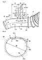
- FIG. 1 is a schematic plan view of essential portions forming part of the intake pipe structure of the internal combustion engine according to the first embodiment of the present invention
- FIG. 2 is a schematic side view of essential portions forming part of the intake pipe structure of the internal combustion engine according to the first embodiment of the present invention
- FIG. 3 is a schematic view showing construction elements forming the internal combustion engine according to the first embodiment of the present invention.
- the intake pipe structure of the internal combustion engine according to the present embodiment is constructed as shown in FIGS. 1 and 2 and assembled with an engine 10.
- the whole construction of the engine 10 is schematically shown in FIG. 3 and comprises a cylinder head 12 having a head cover 11 mounted thereon, a cylinder block 13, and a crankcase 14.
- the cylinder head 12 and the cylinder block 13 in combination form a plurality of cylinders 15 only one of which is shown in FIG. 3 .
- Each of the cylinders 15 has housed therein a piston 16 which is drivably connected with a crank shaft through a connecting rod not shown in the crankcase 14.
- the cylinder head 12 is adapted to accommodate therein a plurality of fuel injection valves to be driven by a crank shaft in synchronism with or independently of the crank shaft.
- the engine 10 has an oil pump such as a gear pump to be driven by the crank shaft to supply the lubricant oil L to the bearings of the cam shafts of the fuel injection valves, the rocker arms, the crank shafts, and other various rotating and sliding portions forming part of the engine 10 for lubrication thereof.
- an oil pump such as a gear pump to be driven by the crank shaft to supply the lubricant oil L to the bearings of the cam shafts of the fuel injection valves, the rocker arms, the crank shafts, and other various rotating and sliding portions forming part of the engine 10 for lubrication thereof.
- Each of the cylinders 15 has a cylinder chamber 17 above the piston 16 to be introduced air through an intake pipe 21 and injected fuel through an injector not shown in response to the stroke of the piston 16.
- the air and fuel mixture in the cylinder chamber 17 is burned under the compression stroke of the piston 16 and then generate exhaust gas to be discharged through an exhaust pipe 22.
- the turbocharger 25 is known in the art and constructed to accommodate therein a gas turbine to be rotated with the energy of the exhaust gas from the engine 10 and an air compressor drivably connected with the gas turbine to be rotated by the gas turbine for sucking air into the cylinder chamber 17 through the intake pipe 21.
- the turbocharger 25 is provided on the passage between the intake pipe 21 and the exhaust pipe 22 to be operable when required for example with a changing system to change the turbocharger 25 into the operation state or the non-operation state.
- the intake pipe 21 is constructed to have an air cleaner 31, an inter cooler 32, a throttle valve 33, and an air pressure sensor 34 for detecting the air pressure in the intake pipe 21 arranged thereon.
- the engine 10 is formed with a ventilation passage (not shown) held in communication with the inner chambers of the cylinder head 12 and the crankcase 14 so that the engine 10 is ventilated by air flows generated in directions shown in arrows indicated in black and white in FIG. 3 .
- the engine 10 is provided at its side portion with a PCV oil separator 41 and a PCV valve 42 acting as a blow-by gas returning valve.
- the PCV valve 42 and the intake pipe 21 at the downstream side of the throttle valve 33 are connected by a PCV hose 43.
- the PCV valve 42 is opened when the inner pressure of the intake pipe 21 is lower than the predetermined pressure (atmospheric pressure, i.e., zero negative pressure) so that the PCV valve 42 can return the blow-by gas leaked from the cylinder chamber 17 to the crankcase 14 through the clearances between the piston 16 and the cylinder 15 to the intake pipe 21 at the downstream side of the throttle valve 33.
- the PCV oil separator 41 functions to remove an oil component from the blow-by gas flowing toward the PCV valve 42 from the upper portion of the crankcase 14.
- a hose 46 which can introduce air in the intake pipe 21 at the upstream side of the throttle valve 33 into the head cover 11 provided in the engine 10.
- the hose 46 has a one-way valve 47 allowing only air flow to be introduced into the head cover 11 from the intake pipe 21.
- the hose 46, the one-way valve 47, the PCV valve 42, and the PCV hose 43 collectively constitute a ventilation system to be operated at the time of a natural intake of air into the engine 10.
- a hose 51 and a ventilation valve 52 operable under the operation of the turbocharger 25 are provided between the intake pipe 21 at the downstream side of the throttle valve 33 and the head cover 11. Between the PCV oil separator 41 and the intake pipe 21 at the upstream side of the turbocharger 25 are provided a PCV valve 56, a one-way valve 57 and a PCV hose 58.
- the hose 51, the ventilation valve 52, the PCV valve 56, the one-way valve 57 and the PCV hose 58 constitute as a whole air introduction means 60 for introducing the fresh air into the head cover 11 when the air pressure of the air in the intake pipe 21 at the downstream side of the throttle valve 33 becomes at a positive value under the operation of the turbocharger 25.
- the intake pipe structure of the internal combustion engine according to the present embodiment mentioned above is adopted in the engine 10 as a joint pipe unit 70 serving to connect the end portion 58d of the PCV hose 58 with the intake pipe 21, for example, at the upstream side of the turbocharger 25.
- the intake passage 21a in the intake pipe 21 and the one end portion 58e of the return passage 58a in the PCV hose 58 are shown in solid lines, respectively, while the intake pipe 21 surrounding and forming the intake passage 21a and the one end portion 58d of the PCV hose 58 surrounding and forming the one end portion 58e of the return passage 58a are shown in phantom lines, respectively.
- the intake pipe 21 is illustrated as an example to have a longitudinal portion partly in the form of a bellow-like shape at the right end portion of FIGS. 1 and 2 . According to the present invention, any other shape and type of intake pipe may be used in lieu of this bellow-like shaped intake pipe 21.
- the joint pipe unit 70 is constituted by a return pipe portion 71 and an intake pipe portion 72.
- the return pipe portion 71 forms part of the one end portion 58d of the PCV hose 58, i.e., return pipe 58 forming the return passage 58a therein, while the intake pipe portion 72 forms part of the intake pipe 21 at the upstream side of the turbocharger 25 forming the intake passage 21a therein.
- the return passage 58a functions to return to the engine 10 the blow-by gas discharged from the cylinder chamber of the engine 10.
- the joint pipe unit 70 forms a joint portion of the one end portion 58e of the return passage 58a and the intake passage 21a of the engine 10 at the upstream side of the turbocharger 25. Also, it will be understood that the joint pipe unit 70 is for communicating an intake passage for introducing air into the engine 10 with a return passage 58a for returning blow-by gas from the engine 10 to the intake passage 21 a as defined in the present invention.
- the return pipe portion 71 of the joint pipe unit 70 is connected at its one end 71a with the intake pipe portion 72.
- the return pipe portion 71 has an inner diameter d1, while the intake pipe portion 72 has an inner diameter d2.
- the return pipe portion 71 has an inner peripheral surface 71s having a first surface section 71s-L1 extending smoothly and continuously in the range of a first length L1 from the one end 71a of the return pipe portion 71 sufficiently larger than the inner diameter d1, for example, in the range of a first length L1 sufficiently larger than the inner diameter d2 of the intake pipe portion 72.
- first surface section 71s-L1 extending smoothly and continuously is intended to mean that the first surface section 71s-L1 has neither annular steps nor other configurations of ledge in the range of the first length L1. It will therefore be understood that neither annular steps nor other shaped steps on the first surface section 71s-L1 leads to no flow cavity on the first surface section 71s-L1, thereby making it possible to prevent the accretion of ice and the separation of ice blocks from being generated on intake pipe 72 and/or the return pipe 71.
- the first length L1 is preferably more than a few times (e.g. three times) the inner diameter d1 of the return pipe portion 71, and may be set in accordance with the level of the heat conductivity from the return pipe portion 71 to the intake pipe portion 72.
- the inner peripheral surface 71s of the return pipe portion 71 has a second surface section 71s-L2 extending in the range of a second length L2 smaller than the first length L1 from the one end 71a of the return pipe portion 71.
- the downstream and upstream sides respectively indicate left and right sides since air is introduced from the right side to the left side in the intake pipe portion 72 toward the engine 10 in FIGS. 1 and 2 .
- the second surface section 71 s-L2 has a downstream side half close to the engine 10 and an upstream side half remote from the engine 10.
- the second surface section 71 s-L2 has a curved surface portion 71w at the downstream side half of the return pipe portion 71, the curved surface portion 71 w being gradually enlarged and curved at the downstream side of the return pipe portion 71, viz., from the right side to the left side in FIG. 2 , toward the one end 71a of the return pipe portion 71 to be connected with the inner peripheral surface 72s of the intake pipe portion 72.
- the curved surface portion 7 1 w of the return pipe portion 71 is curved or flared near the one end 71a at the downstream side thereof and connected at the one end 71a with the intake pipe portion 72.
- the curved surface portion 71 w is curved or flared in the direction of the air flow in the intake passage 21a of the intake pipe 21.
- the curved surface portion 71 w thus curved has a radius of curvature Rw1 (see FIG 2 ), on the cross-section taken on the lines A-A in FIG. 1 , set at a value almost the same as the radius r1 of the first surface section 71s-L1 of the inner peripheral surface 71s of the return pipe portion 71.
- the curvature Rw1 may be set at a value somewhat smaller than the radius r1 of the first surface section 71s-L1 of the inner peripheral surface 71s of the return pipe portion 71 or may be set at a value in the range from the radius r1 of the first surface section 71s-L1 to the diameter d1 of the inner peripheral surface 71s of the return pipe portion 71 according to the present invention.
- the shape of the curved surface portion 71w formed on the inner peripheral surface 71s of the return pipe portion 71 near the one end 71a of the return pipe portion 71 is determined on the basis of an incidence angle of the return pipe portion 71 with respect to the intake pipe portion 72 at the junction of the return pipe portion 71 and the intake pipe portion 72.
- the curved surface portion 71w gradually enlarged and curved at the downstream side of the return pipe portion 71, and thus expanded in cross-section toward the one end 71a of the return pipe portion 71 causes the blow-by gas flow in the return pipe portion 71 to smoothly join the air flow in the intake passage 21 a of the intake pipe 21.
- the return pipe portion 71 is shown in FIGS. 1 and 2 as having an opening 73 at its one end 71a and thus opened on the inner peripheral surface 72s of the intake pipe portion 72.
- the opening 73 is in the form of non-circular shape as best shown in FIG. 1 .
- the opening 73 is enlarged and expanded in a direction angularly deviated from the center axis C of the intake passage 21a at an angle O1 (e.g. 30 degrees) between the expansion direction of the opening 73 and the center axis C of the intake passage 21 a.
- the inner peripheral surface 71s of the return pipe portion 71 has a straight upstream surface portion 71u in the range of a second length L2 from the one end 71s of the return pipe portion 71 at the upstream sidle half of the return pipe portion 71, viz., opposite to the curved surface portion 71 w.
- the straight upstream surface portion 71u has an extension plane crossing the center axis C of the intake passage 21a at the downstream side of the straight upstream surface portion 71 u.
- the crossing angle Q1 between the extension plane of the straight upstream surface portion 71u and the center axis C of the intake passage 21a is set at an angle smaller than 90 degrees as shown in FIG. 2 .
- the straight upstream surface portion 71u of the inner peripheral surface 71s of the return pipe portion 71 is connected with the inner peripheral surface 72s of the intake pipe portion 72 at a ridge portion in the form of roughly an arc shape in cross-section and having a radius of curvature sufficiently smaller than the inner radius r1 of the return pipe portion 71.
- the return pipe portion 71 has an inner peripheral surface 71s having a first surface section 71s-L1 extending smoothly and continuously in the range of a first length L1 from the one end 71a of the return pipe portion 71, and the curved surface portion 71w in the range of a second length L2 is gradually enlarged and curved at the downstream side of the return pipe portion 71 toward the one end 71a of the return pipe portion 71 to continue to the inner peripheral surface 72s of the intake pipe portion 72, so that the flow of the blow-by gas is brought into tight contact with, viz., tightly fits the inner surface of the joint portion of the return pipe portion 71 and the intake pipe portion 72, i.e., the inner surface of the joint pipe unit 70 with no flow cavity therebetween and cannot be separated from the inner surface of the joint pipe unit 70.
- the intake pipe structure according to the first embodiment of the present invention can avoid separation of the gas flow from the inner surface of the joint portion of the return pipe portion 71 and the intake pipe portion 72 and can prevent ice from being accreted on the inner surface of the joint pipe unit 70, thereby making it possible to prevent ice blocks from being separated from the inner surface of the joint pipe unit 70 and to avoid the return passage 58a and the intake passage 21a from being plugged.
- the curved surface portion 71w of the inner peripheral surface 71s of the return pipe portion 71 is gradually enlarged in the direction of air flow in the intake passage 21a at a radius of curvature Rw1 almost the same as the radius r1 of the first surface section 71s-L1 of the inner peripheral surface 71s of the return pipe portion 71, and the opening 73 formed at the one end 71a of the return pipe portion 71 is opened in the downstream direction of the intake passage 21a of the intake pipe 21 with the center axis crossing the center axis C of the intake passage 21a.
- the blow-by gas in the joint pipe unit 70 is not separated from the inner surface of the joint pipe unit 70 even if the direction of the air flow in the intake passage 21a is deviated from the center axis of the intake passage 21a in the vicinity of the junction of the intake passage 21a and the return passage 58a.
- the radius of curvature Rw1 exceeding the inner diameter d1 of the return pipe portion 71 may cause the flow to be turbulent and thus to form a flow cavity at around the enlarged and curved portion of the return pipe portion 71.
- the inner peripheral surface 71s of the return pipe portion 71 has a straight upstream surface portion 71u in the range of a second length L2 from the one end 71a of the return pipe portion 71 and has an extension crossed with the center axis C of the intake passage 21a at the downstream side of the straight upstream surface portion 71u, and the crossing angle Q1 between the extension of the straight upstream surface portion 71u and the center axis C of the intake passage 21a is set at an angle smaller than 90 degrees, so that the blow-by gas is not separated from the inner surface of the joint pipe unit 70 in the upstream area of the one end portion 58e of the return passage 58, thereby causing no ice accretion on the inner surface of the joint pipe unit 70.
- the intake pipe structure of the internal combustion engine is constructed to comprise a return pipe portion 71 having an inner peripheral surface 71 extending smoothly and continuously in the range of a first length L1 from the one end 71a of the return pipe portion 71 sufficiently longer than the inner diameter d1, and having a curved surface portion 71w extending in the range of a second length L2 smaller than the first length L1 from the one end 71a of the return pipe portion 71 and at the downstream side half of the return pipe portion 71, the curved surface portion 71w being gradually enlarged and curved at the downstream side of the return pipe portion 71 toward the one end 71a of the return pipe portion 71 to be connected with the inner peripheral surface 72s of the intake pipe portion 72.
- the intake pipe structure can avoid separation of the gas flow and can prevent ice from being accreted on the inner surface of the joint pipe unit 70, thereby making it possible to prevent ice blocks from being separated from the inner surface of the joint pipe unit 70 and to avoid the intake passage 21a from being plugged.
- the first embodiment may be replaced by another embodiment which comprises a return pipe and an intake pipe directly connected with each other with no use of the above mentioned joint pipe unit 70 according to the present invention.
- the joint pipe unit 70 may be provided in a housing block integrally formed with an engine block accommodating therein the engine 10 according to the present invention.
- FIG. 4 is a schematic plan view of essential portions forming part of the intake pipe structure of the internal combustion engine according to the second embodiment of the present invention
- FIG. 5 is a schematic side view of essential portions forming part of the intake pipe structure of the internal combustion engine according to the second embodiment of the present invention.
- the intake pipe structure of the internal combustion engine according to the second embodiment of the present invention is assembled with the engine 10 explained during the description of the first embodiment of the present invention.
- the constitution elements or parts similar to those of the intake pipe structure of the internal combustion engine according to the first embodiment of the present invention and appearing during the description of the intake pipe structure of the internal combustion engine according to the second embodiment of the present invention will be explained in FIGS. 4 and 5 with the reference numerals the same as the reference numerals in FIGS. 1 to 3 appearing during the description of the intake pipe structure of the internal combustion engine according to the first embodiment of the present invention.
- the intake passage 21a in the intake pipe 21 and the one end portion 58e of the return passage 58a in the PCV hose 58 are shown in solid lines, respectively, while the intake pipe 21 surrounding and forming the intake passage 21 a and the one end portion 58d of the PCV hose 58 surrounding and forming the one end portion 58e of the return passage 58a are shown in phantom lines, respectively.
- the joint pipe unit 80 is constituted by a return pipe portion 81 and an intake pipe portion 82.
- the return pipe portion 81 forms part of the one end portion 58d of the PCV hose 58, i.e., return pipe 58 forming the return passage 58a therein, while the intake pipe portion 82 forms part of the intake pipe 21 at the upstream side of the turbocharger 25 and forming the intake passage 21 a therein.
- the return passage 58a functions to return to the engine 10 the blow-by gas discharged from the cylinder chamber of the engine 10.
- the return pipe portion 81 of the joint pipe unit 80 is connected at its one end 81a with the intake pipe portion 82.
- the return pipe portion 81 has an inner diameter d1, while the intake pipe portion 82 has an inner diameter d2.
- the return pipe portion 81 has an inner peripheral surface 81s having a first surface section 81s-L1 extending smoothly and continuously in the range of a first length L1 from the one end 81a of the return pipe portion 81 sufficiently larger than the inner diameter d1, for example, in the range of a first length L1 sufficiently larger than the inner diameter d2 of the intake pipe portion 82.
- a first surface section 81s-L1 extending smoothly and continuously is intended to mean that the first surface section 81s-L1 has neither annular steps nor other configurations of ledge in the range of the first length L1. It will therefore be understood that neither annular steps nor other configurations of ledge on the first surface section 81s-L1 leads to no flow cavity on the first surface section 81s-L1, thereby making it possible to prevent the accretion of ice and the separation of ice blocks from being generated on intake pipe 82 and/or the return pipe 81.
- the inner peripheral surface 81s of the return pipe portion 81 has a second surface section 81s-L2 extending in the range of a second length L2 smaller than the first length L1 from the one end 81a of the return pipe portion 81.
- the second surface section 81s-L2 has a downstream side half close to the engine 10 and an upstream side half remote from the engine 10.
- the second surface section 81s-L2 has a curved surface portion 81w at the downstream side half of the return pipe portion 81, the curved surface portion 81w being gradually enlarged and curved at the downstream side of the return pipe portion 81, viz., from the right side to the left side in FIG.
- the curved surface portion 81w of the return pipe portion 81 is curved or flared near the one end 81a at the downstream side thereof and connected at the one end 81a with the intake pipe portion 82.
- the curved surface portion 81w is curved or flared in the direction of the air flow in the intake passage 21a of the intake pipe 21.
- the curved surface portion 81 w thus curved has a radius of curvature Rw2 (see FIG. 5 ), on the cross-section taken on the lines A4-A 4 in FIG.
- the return pipe portion 81 is shown in FIGS. 4 and 5 as having an opening 83 at its one end 81a and thus opened on the inner peripheral surface 82s of the intake pipe portion 82.
- the opening 83 is in the form of a non-circular shape as best shown in FIG. 4 .
- the opening 83 is enlarged and curved in a direction angularly deviated from the center axis C of the intake passage 21a at an angle 02 between the expansion direction of the opening 83 and the center axis C of the intake passage 21 a.
- the inner peripheral surface 81s of the return pipe portion 81 has a straight upstream surface portion 81u in the range of a second length L2 from the one end 81s of the return pipe portion 81 at the upstream side half of the return pipe portion 81, viz., opposite to the curved surface portion 81w.
- the straight upstream surface portion 81u has an extension plane crossing the center axis C of the intake passage 21a at the downstream side of the straight upstream surface portion 81u.
- the crossing angle Q2 between the extension plane of the straight upstream surface portion 81 u and the center axis C of the intake passage 21a is set at an angle of, for example, 90 degrees.
- the straight upstream surface portion 81 u of the inner peripheral surface 81s of the return pipe portion 81 is connected with the inner peripheral surface 82s of the intake pipe portion 82 at a ridge portion in the form of roughly an arc shape in cross-section and having a radius of curvature sufficiently smaller than the inner radius r1 of the return pipe portion 81.
- the return pipe portion 81 has an inner peripheral surface 81s having a first surface section 81s-L1 extending smoothly and continuously in the range of a first length L1 from the one end 81a of the return pipe portion 81, and the curved surface portion 81w in the range of a second length L2 is gradually enlarged and curved at the downstream side of the return pipe portion 81 toward the one end 81 a of the return pipe portion 81 to continue to the inner peripheral surface 82s of the intake pipe portion 82, so that the flow of the blow-by gas is brought into tight contact with, viz., tightly fits the inner surface of the joint portion of the return passage 58a and the intake passage 21a, i.e., the inner surface of the joint pipe unit 80 with no flow cavity therebetween and cannot be separated from the inner surface of the joint pipe unit 80.
- the intake pipe structure according to the second embodiment of the present invention can avoid separation of the gas flow and can prevent ice from being accreted on the inner surface of the joint pipe unit 80, thereby making it possible to prevent ice blocks from being separated from the inner surface of the joint pipe unit 80 and to avoid the intake passage 21a from being plugged.
- the curved surface portion 81w of the inner peripheral surface 81s of the return pipe portion 81 is gradually enlarged and curved in the direction of air flow in the intake passage 21a, and the opening 83 formed at the one end 81a of the return pipe portion 81 is opened in the downstream direction of the intake passage 21a of the intake pipe 21 with the center axis crossing the center axis C of the intake passage 21a. Accordingly, the flow in the joint pipe unit 80 is not separated from the inner surface of the joint pipe unit 80 even if the direction of the air flow in the intake passage 21a is deviated from the center axis of the intake passage 21a in the vicinity of the junction of the intake passage 21a and the return passage 58a. This makes it possible to avoid ice accretion on the inner surface of the joint pipe unit 80 stemming from the separation of the blow-by gas.
- the intake pipe structure can avoid separation of the gas flow and can prevent ice from being accreted un the inner surfaces of the joint pipe unit 80, thereby making it possible to prevent ice blocks from being separated from the inner surface of the joint pipe unit 80 and to avoid the intake passage 21a from being plugged.
- the fact that the return pipe portion 81 is vertically arranged when connected with the intake pipe portion 82, and the crossing angle Q2 between the extension of the straight upstream surface portion 81u and the center axis C of the intake passage 21 a is set at an angle of 90 degrees leads to excellent separation of water from the inner surfaces of the return and intake pipe portions.
- FIG. 6 is a schematic plan view of essential portions forming part of the intake pipe structure of the internal combustion engine according to the third embodiment of the present invention
- FIG. 7 is a schematic side view of essential portions forming part of the intake pipe structure of the internal combustion engine according to the third embodiment of the present invention
- FIG. 8 is a cross-sectional view taken along the lines D-D of FIG. 6
- FIG. 9 is a cross-sectional view similar to FIG. 8 but showing another embodiment.
- the intake passage 21a in the intake pipe 21 and the one end portion 58e of the return passage 58a in the PCV hose 58 are shown in solid lines, respectively, while the intake pipe 21 surrounding and forming the intake passage 21a and the one end portion 58d of the PCV hose 58 surrounding and forming the one end portion 58e of the return passage 58a are shown in phantom lines, respectively.
- the joint pipe unit 90 is constituted by a return pipe portion 91 and an intake pipe portion 92.
- the return pipe portion 91 forms the one end portion 58d of the PCV hose 58, i.e., return pipe 58 forming the return passage 58a therein, while the intake pipe portion 92 forms part of the intake pipe 21 at the upstream side of the turbocharger 25 and forming the intake passage 21a therein.
- the return pipe portion 91 of the joint pipe unit 90 is connected at its one end 91 a with the intake pipe portion 92.
- the return pipe portion 91 has an inner diameter d1, while the intake pipe portion 92 has an inner diameter d2.
- the return pipe portion 91 has an inner peripheral surface 91s having a first surface section 91s-L extending smoothly and continuously in the range of a first length L1 from the one end 91a of the return pipe portion 91 sufficiently larger than the inner diameter d1, for example, in the range of a first length L1 sufficiently larger than the inner diameter d2 of the intake pipe portion 92.
- first surface section 91s-L1 extending smoothly and continuously is intended to mean that the first surface section 9is-L1 has neither annular steps nor other configurations of ledge in the range of the first length L1. It will therefore be understood that neither annular steps nor other configurations of ledge on the first surface section 91 s-L leads to no flow cavity on the first surface section 91s-L1, thereby making it possible to prevent the accretion of ice and the separation of ice blocks from being generated on intake pipe 92 and/or the return pipe 91.
- the inner peripheral surface 91s of the return pipe portion 91 has a second surface section 91 s-L2 extending in the range of a second length L2 smaller than the first length L1 from the one end 91a of the return pipe portion 91.
- the second surface section 9 1 s-L2 has a downstream side half close to the engine 10 and an upstream side half remote from the engine 10.
- the second surface section 91 s-L2 has a curved surface portion 91w at the downstream side half of the return pipe portion 91, the curved surface portion 91 w being gradually enlarged and curved at the downstream side of the return pipe portion 91, viz., from the right side to the left side in FIG.
- the curved surface portion 91w is gradually enlarged and curved in the direction of the air flow in the intake passage 21a of the intake pipe 21.
- the curved surface portion 91 w has a radius of curvature Rw3 (see FIG. 7 ), on the cross-section taken on the lines A6-A6 in FIG. 6 , set at a value almost the same as the radius r1 of the first surface section 91s-L1 of the inner peripheral surface 91s of the return pipe portion 91.
- the return pipe portion 91 is shown in FIGS.
- the opening 93 is in the form of a non-circular shape as best shown in FIG. 6 .
- the opening 93 is enlarged and expanded in a direction angularly deviated from the center axis C of the intake passage 21a at an angle 03 (e.g. 15 degrees) between the expansion direction of the opening 93 and the center axis C of the intake passage 21a.
- the inner peripheral surface 91s of the return pipe portion 91 has a straight upstream surface portion 91u in the range of a second length L2 from the one end 91s of the return pipe portion 91 at the upstream side half of the return pipe portion 91, viz., opposite to the curved surface portion 91w.
- the straight upstream surface portion 91u has an extension plane crossing the center axis C of the intake passage 21 a at the downstream side of the straight upstream surface portion 91u.
- the crossing angle Q3 between the extension plane of the straight upstream surface portion 91u and the center axis C of the intake passage 21a is set at an angle of, for example, nearly 90 degrees.
- the straight upstream surface portion 91u of the inner peripheral surface 91s of the return pipe portion 91 is connected with the inner peripheral surface 92s of the intake pipe portion 92 at a ridge portion in the form of roughly an arc shape in cross-section and having a radius of curvature sufficiently smaller than the inner radius r1 of the return pipe portion 91.
- the intake pipe portion 92 has an inner protuberant surface section 92p inclined to gradually become high toward the opening 93 of the return pipe portion 91 with the distance between the center axis C of the intake pipe portion 92 and the inner protuberant surface section 92p being diminished.
- the inner protuberant surface section 92p of the intake pipe portion 92 becomes wide in the circumferential direction toward the opening 93 of the return pipe portion 91.
- the inclination angle of the inner protuberant surface section 92p with respect to the center axis C of the intake pipe passage 21 a is set at a value within the range of 5 degrees to curb the pressure loss caused by the inner protuberant surface section 92p.
- the inner protuberant surface section 92p of the intake pipe portion 92 protrudes toward the center axis C of the intake pipe passage 21 a with its height gradually becoming large toward the opening 93 of the return pipe portion 91, viz., with the distance between the center axis C of the intake pipe portion 92 and the inner protuberant surface section 92p being diminished toward the opening 93 of the return pipe portion 91.
- the inner protuberant surface section 92p of the intake pipe portion 92 is shown in FIG. 8 to have a recess 21v on the outer peripheral surface thereof.
- the inner protuberant surface section 92p of the intake pipe portion 92 at the upstream side of the opening 93 of the return pipe portion 91 becomes wide in the circumferential direction toward the opening 93 of the return pipe portion 91.
- the inner protuberant surface section 92p of the intake pipe portion 92 is in form of a triangular shape with the recess 21v having both sides 2 1 va and 21vb straightly extending and gradually becoming narrow in width in the upstream direction from the opening 93 and a bottom side 21vc in close proximity of the opening 93.
- the recess 21v has an upstream end chamfered at a point most distant from the opening 93 as best shown in FIG. 6 .
- the peripheral portion of the inner protuberant surface section 92p of the intake pipe portion 92 viz., the sides 21 va and 21 vb of the recess 21v are chamfered at their radially inward and outward corners at a radius of curvature "ri" somewhat smaller than the depth "dp" to be connected with the inner peripheral surface 92s of the intake pipe portion 92, thereby ensuring a smooth and stepless connection between the inner protuberant surface section 92p of the intake pipe portion 92 and the inner peripheral surface 92s of the intake pipe portion 92.
- the sides 21 va and 21 vb of the recess 21 v may be curved inwardly or outwardly according to the present invention.
- the cross-section of the intake passage 21 a is in the form of non-circular shape in the range of the connection zones Z1 to Z3 as shown in FIG. 7 .
- the cross-section area of the intake passage 21a in the connection zone Z1 gradually decreases in the direction toward the opening 93.
- the cross-section area of the intake passage 21a in the connection zone Z2 is nearly constant in its axial direction thereof.
- the cross-section area of the intake passage 21a in the connection zone 3 gradually increases in the direction away from the opening 93.
- the cross-section area Sd1 of the intake passage 21a at the immediate upstream side of the connection zone Z1 is equal to the cross-section area Sd2 of the intake passage 21a at the immediate downstream side of the connection zone Z3.
- the fluctuation of the cross-section area of the intake passage 21a in the connection zones Z1 to Z3 is within the range of 3 %.
- the intake pipe structure of the internal combustion engine is constructed to comprise a return pipe portion 91 having an inner peripheral surface 91s extending smoothly and continuously in the range of a first length L1 from the one end 91a of the return pipe portion 91, so that the flow of the blow-by gas is brought into tight contact with, viz., tightly fits the inner surface of the joint portion of the return passage 58a and the intake passage 21a, i.e., the inner surface of the joint pipe unit 90 with no flow cavity therebetween and cannot be separated from the inner surface of the joint pipe unit 90.
- the intake pipe portion 92 has an inner protuberant surface section 92p protruded and inclined at the upstream of and toward the opening 93 of the return pipe portion 91 with a recess 21v formed on the outer peripheral surface thereof, the inner protuberant surface section 92p can prevent the air flow on the inner protuberant surface section 92p from being introduced into the opening 93 of the return pipe portion 91.
- the intake pipe structure according to the present invention can prevent ice from being accreted on the inner surface of the joint pipe unit 90, and can prevent ice blocks from being separated from the inner surface of the joint pipe unit 90. As a result, there is neither ineffectiveness to the blow-by gas flow nor raised inner pressure of the crankcase 14.
- the curved surface portion 91 w of the inner peripheral surface 91s of the return pipe portion 91 is gradually enlarged and curved in the direction of air flow in the intake passage 21a, and the opening 93 formed at the one end 91a of the return pipe portion 91 is opened in the downstream direction of the intake passage 21a of the intake pipe 21 with the center axis crossing the center axis C of the intake passage 21a. Accordingly, the flow in the joint pipe unit 90 is not separated from the inner surface of the joint pipe unit 90 even if the direction of the air flow in the intake passage 21a is deviated from the center axis of the intake passage 21a in the vicinity of the junction of the intake passage 21a and the return passage 59a. This makes it possible to avoid ice accretion on the inner surface of the joint pipe unit 90 stemming from the separation of the blow-by gas.
- the intake pipe structure according to the present embodiment can avoid ice accretion on the inner surface of the joint pipe unit 90 stemming from the separation of the blow-by gas in a similar manner to the first and second embodiments mentioned above.
- the inclined portion may be replaced by an inclined portion 92h having a flat surface on the inner peripheral surface of the intake pipe portion 92 as shown in FIG. 9 with respect to the inclined portion formed as shown in FIG. 8 .
- the area of the flat surface of the inclined portion 92h may be larger than that of the recess 21v, viz., the inclined portion formed by the inner protuberant surface section 92p of the intake pipe portion 92 as shown in FIGS. 6 to 8 .
- the inclined portion 92h of the intake pipe portion 92 is inclined with the distance between the flat surface of the inclined portion 92h and the center axis C of the intake passage 21a decreasing toward the opening 93 of the return pipe portion 91.
- the intake pipe portion 92 at the upstream side of the junction point of the return passage 58a and the intake passage 21 a, viz., at the upstream side of the opening 93 may be arranged with respect to the return pipe portion 91 to have its center axis inclined with respect to the center axis of the return pipe portion 91 in a direction decreasing an angle Q3 between the center axis of the intake pipe portion 92 and the center axis of the return pipe portion 91.
- the angle between the straight portion Cz (see FIG. 7 ) of the center axis C of the intake passage 21a and the center axis of the return passage 58a in the vicinity of the crossing point of the above axes of the intake passage 21a and the return passage 58a is 90 degrees, while the angle between the center axis C of the intake passage 21a at the upstream of the opening 93 and the center axis of the return passage 58a is less than 90 degrees. For this reason, the air flow adjacent to the opening 93 is deviated from the center axis C of the intake passage 21a.
- the intake pipe structure of the internal combustion engine is provided with an return pipe portion having an inner peripheral surface having a first surface section extending smoothly and continuously in the range of a first length from the one end of the return pipe portion and a second surface section extending in the range of a second length smaller than the first length from the one end of the return pipe portion and a curved surface portion at the downstream side half of the return pipe portion, the curved surface portion being gradually enlarged and curved at the downstream side of the return pipe portion.
- the intake pipe structure of the internal combustion engine according to the present invention is provided with an return pipe portion having an inner peripheral surface having a first surface section extending smoothly and continuously in the range of a first length from the one end of the return pipe portion and an intake pipe portion having an inner protuberant surface section inclined to gradually become high toward the opening of the return pipe portion.
- the intake pipe structure of the internal combustion engine thus constructed above makes it possible to avoid the flow in the joint pipe unit from being separated from the inner surface of the joint pipe unit, to prevent the air flow from being introduced into the opening of the return pipe portion due to the air flow deviated away from the inner protuberant surface section, and to prevent ice from being accreted on the inner surface of the joint pipe unit. Further, there is neither ineffectiveness to the blow-by gas flow nor raised inner pressure of the crankcase to ensure that the intake pipe structure according to the present invention is excellent in reliability when used in the cold regions and environments.
Landscapes
- Engineering & Computer Science (AREA)
- Chemical & Material Sciences (AREA)
- Combustion & Propulsion (AREA)
- Mechanical Engineering (AREA)
- General Engineering & Computer Science (AREA)
- Lubrication Details And Ventilation Of Internal Combustion Engines (AREA)
Claims (7)
- Ansaugrohrkonstruktion einer Verbrennungskraftmaschine (10), umfassend:eine Anschlußrohreinheit (70, 80, 90) zum kommunizierenden Verbinden eines Ansaugkanals (21 a) zum Einleiten von Luft in die Verbrennungskraftmaschine (10) mit einem Rückführkanal (58a) zum Rückführen von Blow-by-Gas von der Verbrennungskraftmaschine in den Ansaugkanal (21 a),wobei die Anschlußrohreinheit (70, 80, 90) von einem Ansaugrohrabschnitt (72, 82, 92), in dem der Ansaugkanal (21 a) ausgebildet ist, und einem Rückführrohrabschnitt (71, 81, 91), in dem der Rückführkanal (58a) ausgebildet ist, gebildet wird und ein erstes Ende (71 a, 81 a, 91 a) umfaßt, welches mit dem Ansaugrohrabschnitt (72, 82, 92) verbunden ist und welches eine Öffnung (73, 83, 93) aufweist, die zu dem Ansaugrohrabschnitt (72, 82, 92) hin geöffnet ist, wobei der Rückführrohrabschnitt (71, 81, 91) einen Innendurchmesser (d1) und eine innere Umfangsfläche (71 s, 81 s, 91 s) aufweist,wobei die Mittelachse (C) des Ansaugrohrabschnitts (72, 82, 92) in der Nähe des ersten Endes (71 a, 81 a, 91 a) und die Mittelachse des Rückführrohrabschnitts (71, 81, 91) in einer gemeinsamen Ebene P liegen,wobei die innere Umfangsfläche (71 s, 81 s, 91 s) des Rückführrohrabschnitts einen ersten Flächenteil (71s-L1, 81s-L1, 91s-L1) aufweist, der von dem ersten Ende (71 a, 81 a, 91 a) des Rückführrohrabschnitts beabstandet ist und sich glatt und kontinuierlich ohne ringförmige Stufen oder andere Absatzausbildungen innerhalb des Bereiches einer ersten Länge (L1) erstreckt, welche von dem ersten Ende (71 a, 81 a, 91 a) des Rückführrohrabschnitts aus festgelegt ist und welche größer als der Innendurchmesser (d1) ist,wobei die innere Umfangsfläche (71 s, 81 s, 91 s) einen zweiten Flächenteil (71 s-L2, 81 s-L2, 91 s-L2) aufweist, der sich von dem ersten Flächenteil (71 s-L1, 81 s-L1, 91s-L1) bis zu dem ersten Ende (71 a, 81 a, 91 a) des Rückführrohrabschnitts innerhalb des Bereiches einer zweiten Länge (L2) erstreckt, welche von dem ersten Ende (71 a, 81 a, 91 a) des Rückführrohrabschnitts aus festgelegt ist und welche kleiner als die erste Länge (L1) ist,wobei der zweite Flächenteil (71 s-L2, 81 s-L2, 91 s-L2) einen gekrümmten Flächenabschnitt (71 w, 81 w, 91 w) aufweist, der auf der stromabwärtigen Seite des Rückführrohrabschnitts (71, 81, 91) allmählich vergrößert und gekrümmt ist, um die Fläche des ersten Flächenteils kontinuierlich zu einer inneren Umfangsfläche (72s, 82s, 92s) des Ansaugrohrabschnitts fortzusetzen, wodurch er die Öffnung (73, 83, 93) auf der stromabwärtigen Seite auf eine solche Weise vergrößert, daß die Öffnung (73, 83, 93) eine nicht kreisförmige Gestalt hat,wobei der gekrümmte Flächenabschnitt (71 w, 81 w, 91 w) ein maximales Ausmaß der Vergrößerung zu einer Erweiterungsrichtung hin aufweist, so daß die Öffnung (73, 83, 93) ein maximales Ausmaß der Vergrößerung und Erweiterung in dieser Erweiterungsrichtung aufweist,dadurch gekennzeichnet, daß die Erweiterungsrichtung nicht in der gemeinsamen Ebene P liegt, sondern die Erweiterungsrichtung eine Winkelabweichung von der Mittelachse (C) des Ansaugrohrabschnitts (72, 82, 92) aufweist.
- Ansaugrohrkonstruktion nach Anspruch 1, wobei der gekrümmte Flächenabschnitt (71 w, 81 w, 91 w) in der Richtung des Luftstroms in dem Ansaugrohrabschnitt (72, 82, 92) gekrümmt ist.
- Ansaugrohrkonstruktion nach Anspruch 1 oder 2, wobei die innere Umfangsfläche (71 s, 81 s, 91 s) des Rückführrohrabschnitts (71, 81, 91) einen geraden stromaufwärtigen Flächenteil (71 u, 81 u, 91 u) aufweist, welcher sich innerhalb des Bereiches der zweiten Länge (L2) befindet, die von dem ersten Ende (71 a, 81 a, 91 a) des Rückführrohrabschnitts aus festgelegt ist, und welcher auf der stromaufwärtigen Seite des Ansaugrohrabschnitt (72, 82, 92) positioniert ist, wobei der gerade stromaufwärtige Flächenteil eine Erstreckungsebene aufweist, welche die Mittelachse (C) des Ansaugrohrabschnitts unter einem Kreuzungswinkel (Q1, Q2, Q3) zwischen der Erstreckungsebene des geraden stromaufwärtigen Flächenteils (71 u, 81 u, 91 u) und der Mittelachse (C) des Ansaugrohrabschnitts (72, 82, 92) auf der stromaufwärtigen Seite der Erstreckungsebene kreuzt, der auf weniger als 90 Grad festgelegt ist.
- Ansaugrohrkonstruktion nach einem der Ansprüche 1 bis 3, wobei der Ansaugrohrabschnitt (92) einen inneren vorstehenden Flächenteil (92p) aufweist, der auf der stromaufwärtigen Seite der Öffnung (93) des Rückführrohrabschnitts (91) und in deren Nähe positioniert ist und in den Ansaugrohrabschnitt (92) hineinragt.
- Ansaugrohrkonstruktion nach Anspruch 4, wobei der innere vorstehende Flächenteil (92p) des Ansaugrohrabschnitts (92) geneigt ist, wobei sich der Abstand zwischen der Mittelachse (C) des Ansaugrohrabschnitts (92) und dem inneren vorstehenden Flächenteil (92p) zu der Öffnung (93) des Rückführrohrabschnitts (91) hin verkleinert.
- Ansaugrohrkonstruktion nach Anspruch 4 oder 5, wobei sich der innere vorstehende Flächenteil (92p) des Ansaugrohrabschnitts (92) in der Umfangsrichtung zu der Öffnung (93) des Rückführrohrabschnitts (91) hin verbreitert.
- Ansaugrohrkonstruktion nach einem der Ansprüche 4 bis 6, wobei der innere vorstehende Flächenteil (92p) des Ansaugrohrabschnitts (92) eine dreieckige Form aufweist.
Applications Claiming Priority (2)
| Application Number | Priority Date | Filing Date | Title |
|---|---|---|---|
| JP2007336974A JP4748152B2 (ja) | 2007-12-27 | 2007-12-27 | 内燃機関の吸気管構造 |
| PCT/JP2008/003085 WO2009084144A1 (en) | 2007-12-27 | 2008-10-29 | Intake pipe structure of internal combustion engine |
Publications (2)
| Publication Number | Publication Date |
|---|---|
| EP2245279A1 EP2245279A1 (de) | 2010-11-03 |
| EP2245279B1 true EP2245279B1 (de) | 2012-02-29 |
Family
ID=40282335
Family Applications (1)
| Application Number | Title | Priority Date | Filing Date |
|---|---|---|---|
| EP08868347A Not-in-force EP2245279B1 (de) | 2007-12-27 | 2008-10-29 | Einlassrohrstruktur eines verbrennungsmotors |
Country Status (6)
| Country | Link |
|---|---|
| US (1) | US8151777B2 (de) |
| EP (1) | EP2245279B1 (de) |
| JP (1) | JP4748152B2 (de) |
| CN (1) | CN101960105B (de) |
| AT (1) | ATE547594T1 (de) |
| WO (1) | WO2009084144A1 (de) |
Families Citing this family (28)
| Publication number | Priority date | Publication date | Assignee | Title |
|---|---|---|---|---|
| JP5319461B2 (ja) * | 2009-08-28 | 2013-10-16 | ダイハツ工業株式会社 | 排気ターボ過給機付き内燃機関におけるブローバイガス処理装置 |
| US8205604B2 (en) * | 2009-11-25 | 2012-06-26 | GM Global Technology Operations LLC | Crankcase vent nozzle for internal combustion engine |
| DE102010005828A1 (de) * | 2010-01-27 | 2011-07-28 | GM Global Technology Operations LLC, ( n. d. Ges. d. Staates Delaware ), Mich. | Lufteinlassvorrichtung |
| DE102010019931A1 (de) * | 2010-05-08 | 2011-11-10 | Volkswagen Ag | Verbrennungsluft führender Fluidleitungsabschnitt einer Verbrennungsluftanlage |
| FR2973444A1 (fr) * | 2011-03-29 | 2012-10-05 | Renault Sa | Circuit de circulation d'air d'un moteur de vehicule |
| US8695339B2 (en) * | 2011-05-13 | 2014-04-15 | GM Global Technology Operations LLC | Blowby flow control system for a turbocharged engine |
| JP5825903B2 (ja) * | 2011-07-26 | 2015-12-02 | 愛三工業株式会社 | 樹脂製インテークマニホールド |
| JP2013133796A (ja) * | 2011-12-27 | 2013-07-08 | Yanmar Co Ltd | エンジン装置 |
| JP2013185474A (ja) * | 2012-03-07 | 2013-09-19 | Aisan Industry Co Ltd | インテークマニホールド |
| US9243550B2 (en) * | 2012-03-12 | 2016-01-26 | Ford Global Technologies, Llc | Turbocharger compressor inlet flow control |
| US20140238338A1 (en) * | 2013-02-22 | 2014-08-28 | Hyundai Motor Company | Variable compression engine |
| US9316183B2 (en) * | 2013-08-15 | 2016-04-19 | Ford Global Technologies, Llc | Air intake duct ice ingestion features |
| KR101496034B1 (ko) * | 2013-09-10 | 2015-02-25 | 지엠 글로벌 테크놀러지 오퍼레이션스 엘엘씨 | 차량용 크랭크케이스 환기장치 |
| JP6225885B2 (ja) * | 2014-11-14 | 2017-11-08 | マツダ株式会社 | ブローバイガス還流装置 |
| JP6502596B2 (ja) * | 2015-04-06 | 2019-04-17 | 本田技研工業株式会社 | 内燃機関 |
| EP3411571B1 (de) * | 2016-02-05 | 2021-10-27 | Cummins, Inc. | System zum ausgleich von gegendruck in motorzylindern |
| CN106930869A (zh) * | 2017-01-23 | 2017-07-07 | 宁波捷豹振动控制系统有限公司 | 空滤进气管 |
| US10648404B2 (en) | 2017-03-20 | 2020-05-12 | Advanced Flow Engineering, Inc. | Vent insert |
| US10711745B2 (en) * | 2017-06-01 | 2020-07-14 | Kubota Corporation | Work vehicle |
| EP3418515B1 (de) * | 2017-06-21 | 2020-02-12 | FCA Italy S.p.A. | System zur rückführung von blowby-gas in einen ansaugkanal einer brennkraftmaschine, das system mit einer enteisungsvorrichtungs |
| KR102054811B1 (ko) * | 2018-06-11 | 2019-12-11 | 주식회사 현대케피코 | 흡기매니폴드의 pcv 출구 결빙 방지 장치 |
| CN110608116A (zh) * | 2018-06-14 | 2019-12-24 | 丰田纺织株式会社 | 用于内燃机的进气管 |
| JP6534766B1 (ja) * | 2018-08-28 | 2019-06-26 | 株式会社ケーヒン | 吸気マニホールド |
| JP7092652B2 (ja) * | 2018-12-18 | 2022-06-28 | 株式会社クボタ | ブローバイガス還流装置 |
| JP7287261B2 (ja) * | 2019-12-18 | 2023-06-06 | トヨタ紡織株式会社 | 吸気ダクト |
| CN111927593A (zh) * | 2020-08-06 | 2020-11-13 | 一汽解放汽车有限公司 | 一种增压器进气接管及发动机 |
| CN112199831B (zh) * | 2020-09-28 | 2022-04-05 | 中国北方发动机研究所(天津) | 一种高流通能力排气道设计方法 |
| KR20230027990A (ko) * | 2021-08-20 | 2023-02-28 | 현대자동차주식회사 | 터보차저용 엘보우 및 이의 연결구조 |
Family Cites Families (26)
| Publication number | Priority date | Publication date | Assignee | Title |
|---|---|---|---|---|
| US1543732A (en) * | 1924-12-06 | 1925-06-30 | Joseph H Staley | Preheating humidifier |
| US3415233A (en) * | 1966-10-17 | 1968-12-10 | William R. Drysdale | Vacuum flow control for crankcase ventilation |
| DE3625376C1 (de) * | 1986-07-26 | 1987-10-29 | Porsche Ag | Kurbelgehaeuseentlueftung fuer Kraftfahrzeuge |
| JPH0240964A (ja) * | 1988-08-01 | 1990-02-09 | Toyota Autom Loom Works Ltd | 電流センス機能付sit |
| JPH02126012A (ja) * | 1988-11-05 | 1990-05-15 | Osaka Gas Co Ltd | ノズル面積可変ガスバーナ |
| JPH02126012U (de) | 1989-03-27 | 1990-10-17 | ||
| JPH0720531B2 (ja) * | 1989-07-07 | 1995-03-08 | 新日鐵化学株式会社 | 液相酸化湿式脱硫装置 |
| JP2511758Y2 (ja) | 1989-09-01 | 1996-09-25 | 日産ディーゼル工業株式会社 | 内燃機関のブロ―バイガス還流装置 |
| JPH0447116A (ja) * | 1990-06-14 | 1992-02-17 | Nissan Motor Co Ltd | エンジンの排気浄化装置 |
| JPH0447116U (de) | 1990-08-24 | 1992-04-22 | ||
| JP2560299Y2 (ja) | 1991-09-27 | 1998-01-21 | 日産ディーゼル工業株式会社 | ブローバイガス還流通路の配管構造 |
| JPH09317569A (ja) * | 1996-05-22 | 1997-12-09 | Nippon Soken Inc | エンジンのガス還流装置 |
| JPH10331621A (ja) * | 1997-05-30 | 1998-12-15 | Suzuki Motor Corp | 内燃機関のブリーザ通路構造 |
| JP4036988B2 (ja) * | 1998-11-04 | 2008-01-23 | 本田技研工業株式会社 | ブローバイガス還元装置 |
| US6058917A (en) * | 1999-01-14 | 2000-05-09 | Vortex Automotive Corporation | Method and apparatus for treating crankcase emissions |
| US6148807A (en) * | 1999-06-21 | 2000-11-21 | Ford Global Technologies, Inc. | Crankcase fluid processing system for automotive engine |
| JP2003065171A (ja) * | 2001-08-23 | 2003-03-05 | Toyota Motor Corp | 内燃機関の吸気装置 |
| JP3904425B2 (ja) * | 2001-10-10 | 2007-04-11 | 本田技研工業株式会社 | 内燃機関のブローバイガス処理装置 |
| JP3915550B2 (ja) * | 2002-02-28 | 2007-05-16 | 株式会社デンソー | 内燃機関の吸気装置 |
| JP4050935B2 (ja) * | 2002-06-07 | 2008-02-20 | トヨタ紡織株式会社 | 内燃機関用吸気装置 |
| JP4059130B2 (ja) * | 2003-04-15 | 2008-03-12 | 日産自動車株式会社 | 内燃機関のブローバイガス還流装置 |
| DE10331344B4 (de) * | 2003-07-11 | 2015-10-22 | Daimler Ag | Verfahren zum Entlüften eines Kurbelgehäuses einer Brennkraftmaschine |
| JP2005120977A (ja) * | 2003-10-20 | 2005-05-12 | Kawasaki Heavy Ind Ltd | エンジンのブリーザ構造 |
| JP2006063884A (ja) * | 2004-08-26 | 2006-03-09 | Mazda Motor Corp | エンジンのブローバイガス還流装置 |
| DE102004043545A1 (de) * | 2004-09-09 | 2006-03-30 | Audi Ag | Kurbelgehäuseentlüftungseinrichtung für eine Brennkraftmaschine eines Kraftfahrzeuges |
| CN200982215Y (zh) * | 2006-07-12 | 2007-11-28 | 比亚迪股份有限公司 | 内燃机闭式曲轴箱强制通风管路 |
-
2007
- 2007-12-27 JP JP2007336974A patent/JP4748152B2/ja not_active Expired - Fee Related
-
2008
- 2008-10-29 US US12/810,757 patent/US8151777B2/en not_active Expired - Fee Related
- 2008-10-29 CN CN2008801276079A patent/CN101960105B/zh not_active Expired - Fee Related
- 2008-10-29 EP EP08868347A patent/EP2245279B1/de not_active Not-in-force
- 2008-10-29 AT AT08868347T patent/ATE547594T1/de active
- 2008-10-29 WO PCT/JP2008/003085 patent/WO2009084144A1/en not_active Ceased
Also Published As
| Publication number | Publication date |
|---|---|
| US8151777B2 (en) | 2012-04-10 |
| JP2009156209A (ja) | 2009-07-16 |
| CN101960105A (zh) | 2011-01-26 |
| ATE547594T1 (de) | 2012-03-15 |
| JP4748152B2 (ja) | 2011-08-17 |
| EP2245279A1 (de) | 2010-11-03 |
| CN101960105B (zh) | 2012-10-24 |
| US20100269804A1 (en) | 2010-10-28 |
| WO2009084144A1 (en) | 2009-07-09 |
Similar Documents
| Publication | Publication Date | Title |
|---|---|---|
| US8151777B2 (en) | Intake pipe structure of internal combustion engine | |
| US8511291B2 (en) | Positive crankcase ventilation system, cylinder head used for positive crankcase ventilation system, internal combustion engine including positive crankcase ventilation system, and positive crankcase ventilation method | |
| JP6765260B2 (ja) | 過給機付内燃機関のブローバイガス処理装置 | |
| CN104373204A (zh) | 进气管道的冰吸收特性 | |
| JP2009281317A (ja) | 内燃機関の吸気管構造 | |
| CN102071987A (zh) | 用于内燃发动机的曲轴箱通风管嘴 | |
| CN104334842B (zh) | 用于避免内燃机中提前着火的方法与内燃机及交通工具 | |
| JP6225885B2 (ja) | ブローバイガス還流装置 | |
| JP5504198B2 (ja) | エンジン | |
| RU2653038C1 (ru) | Впускной коллектор и двигатель, включающий в себя впускной коллектор | |
| EP3569832B1 (de) | Motor mit kurbelgehäusegas-rückführsystem | |
| CN216950628U (zh) | 带增压器的发动机 | |
| CN215633224U (zh) | 一种发动机闭式曲轴箱通风系统回气管路布置 | |
| JP2010151062A (ja) | 内燃機関の可変吸気装置 | |
| CN207194993U (zh) | 进气系统多功能谐振腔 | |
| CN222414981U (zh) | 曲轴箱油气分离与通风系统及发动机总成 | |
| CN215408806U (zh) | 一种曲轴箱通风系统及车辆 | |
| KR101956391B1 (ko) | 크랭크 케이스의 결빙 방지 장치 | |
| CN216894581U (zh) | 用于发动机的呼吸管及发动机总成 | |
| JP7348609B2 (ja) | ブローバイガス混合継手およびエンジン | |
| JP4882829B2 (ja) | ブローバイガスの還流量を調整するバルブ | |
| JP2016065527A (ja) | ブローバイガス還流装置、ブローバイガス管の接続部材、エンジンシステム | |
| JP7128101B2 (ja) | 内燃機関 | |
| CN209925050U (zh) | 一种发动机曲轴箱通气管的加热结构 | |
| CN110608077A (zh) | 一种车辆及曲轴箱污染物的处理系统 |
Legal Events
| Date | Code | Title | Description |
|---|---|---|---|
| PUAI | Public reference made under article 153(3) epc to a published international application that has entered the european phase |
Free format text: ORIGINAL CODE: 0009012 |
|
| 17P | Request for examination filed |
Effective date: 20100727 |
|
| AK | Designated contracting states |
Kind code of ref document: A1 Designated state(s): AT BE BG CH CY CZ DE DK EE ES FI FR GB GR HR HU IE IS IT LI LT LU LV MC MT NL NO PL PT RO SE SI SK TR |
|
| AX | Request for extension of the european patent |
Extension state: AL BA MK RS |
|
| 17Q | First examination report despatched |
Effective date: 20110225 |
|
| DAX | Request for extension of the european patent (deleted) | ||
| GRAP | Despatch of communication of intention to grant a patent |
Free format text: ORIGINAL CODE: EPIDOSNIGR1 |
|
| GRAS | Grant fee paid |
Free format text: ORIGINAL CODE: EPIDOSNIGR3 |
|
| GRAA | (expected) grant |
Free format text: ORIGINAL CODE: 0009210 |
|
| AK | Designated contracting states |
Kind code of ref document: B1 Designated state(s): AT BE BG CH CY CZ DE DK EE ES FI FR GB GR HR HU IE IS IT LI LT LU LV MC MT NL NO PL PT RO SE SI SK TR |
|
| REG | Reference to a national code |
Ref country code: GB Ref legal event code: FG4D Ref country code: CH Ref legal event code: EP |
|
| REG | Reference to a national code |
Ref country code: AT Ref legal event code: REF Ref document number: 547594 Country of ref document: AT Kind code of ref document: T Effective date: 20120315 |
|
| REG | Reference to a national code |
Ref country code: IE Ref legal event code: FG4D |
|
| REG | Reference to a national code |
Ref country code: DE Ref legal event code: R096 Ref document number: 602008013846 Country of ref document: DE Effective date: 20120426 |
|
| REG | Reference to a national code |
Ref country code: NL Ref legal event code: VDEP Effective date: 20120229 |
|
| LTIE | Lt: invalidation of european patent or patent extension |
Effective date: 20120229 |
|
| PG25 | Lapsed in a contracting state [announced via postgrant information from national office to epo] |
Ref country code: IS Free format text: LAPSE BECAUSE OF FAILURE TO SUBMIT A TRANSLATION OF THE DESCRIPTION OR TO PAY THE FEE WITHIN THE PRESCRIBED TIME-LIMIT Effective date: 20120629 Ref country code: NL Free format text: LAPSE BECAUSE OF FAILURE TO SUBMIT A TRANSLATION OF THE DESCRIPTION OR TO PAY THE FEE WITHIN THE PRESCRIBED TIME-LIMIT Effective date: 20120229 Ref country code: HR Free format text: LAPSE BECAUSE OF FAILURE TO SUBMIT A TRANSLATION OF THE DESCRIPTION OR TO PAY THE FEE WITHIN THE PRESCRIBED TIME-LIMIT Effective date: 20120229 Ref country code: LT Free format text: LAPSE BECAUSE OF FAILURE TO SUBMIT A TRANSLATION OF THE DESCRIPTION OR TO PAY THE FEE WITHIN THE PRESCRIBED TIME-LIMIT Effective date: 20120229 Ref country code: NO Free format text: LAPSE BECAUSE OF FAILURE TO SUBMIT A TRANSLATION OF THE DESCRIPTION OR TO PAY THE FEE WITHIN THE PRESCRIBED TIME-LIMIT Effective date: 20120529 |
|
| PG25 | Lapsed in a contracting state [announced via postgrant information from national office to epo] |
Ref country code: GR Free format text: LAPSE BECAUSE OF FAILURE TO SUBMIT A TRANSLATION OF THE DESCRIPTION OR TO PAY THE FEE WITHIN THE PRESCRIBED TIME-LIMIT Effective date: 20120530 Ref country code: BE Free format text: LAPSE BECAUSE OF FAILURE TO SUBMIT A TRANSLATION OF THE DESCRIPTION OR TO PAY THE FEE WITHIN THE PRESCRIBED TIME-LIMIT Effective date: 20120229 Ref country code: LV Free format text: LAPSE BECAUSE OF FAILURE TO SUBMIT A TRANSLATION OF THE DESCRIPTION OR TO PAY THE FEE WITHIN THE PRESCRIBED TIME-LIMIT Effective date: 20120229 Ref country code: FI Free format text: LAPSE BECAUSE OF FAILURE TO SUBMIT A TRANSLATION OF THE DESCRIPTION OR TO PAY THE FEE WITHIN THE PRESCRIBED TIME-LIMIT Effective date: 20120229 Ref country code: PT Free format text: LAPSE BECAUSE OF FAILURE TO SUBMIT A TRANSLATION OF THE DESCRIPTION OR TO PAY THE FEE WITHIN THE PRESCRIBED TIME-LIMIT Effective date: 20120629 |
|
| REG | Reference to a national code |
Ref country code: AT Ref legal event code: MK05 Ref document number: 547594 Country of ref document: AT Kind code of ref document: T Effective date: 20120229 |
|
| PG25 | Lapsed in a contracting state [announced via postgrant information from national office to epo] |
Ref country code: CY Free format text: LAPSE BECAUSE OF FAILURE TO SUBMIT A TRANSLATION OF THE DESCRIPTION OR TO PAY THE FEE WITHIN THE PRESCRIBED TIME-LIMIT Effective date: 20120229 |
|
| PG25 | Lapsed in a contracting state [announced via postgrant information from national office to epo] |
Ref country code: EE Free format text: LAPSE BECAUSE OF FAILURE TO SUBMIT A TRANSLATION OF THE DESCRIPTION OR TO PAY THE FEE WITHIN THE PRESCRIBED TIME-LIMIT Effective date: 20120229 Ref country code: CZ Free format text: LAPSE BECAUSE OF FAILURE TO SUBMIT A TRANSLATION OF THE DESCRIPTION OR TO PAY THE FEE WITHIN THE PRESCRIBED TIME-LIMIT Effective date: 20120229 Ref country code: DK Free format text: LAPSE BECAUSE OF FAILURE TO SUBMIT A TRANSLATION OF THE DESCRIPTION OR TO PAY THE FEE WITHIN THE PRESCRIBED TIME-LIMIT Effective date: 20120229 Ref country code: RO Free format text: LAPSE BECAUSE OF FAILURE TO SUBMIT A TRANSLATION OF THE DESCRIPTION OR TO PAY THE FEE WITHIN THE PRESCRIBED TIME-LIMIT Effective date: 20120229 Ref country code: SI Free format text: LAPSE BECAUSE OF FAILURE TO SUBMIT A TRANSLATION OF THE DESCRIPTION OR TO PAY THE FEE WITHIN THE PRESCRIBED TIME-LIMIT Effective date: 20120229 Ref country code: SE Free format text: LAPSE BECAUSE OF FAILURE TO SUBMIT A TRANSLATION OF THE DESCRIPTION OR TO PAY THE FEE WITHIN THE PRESCRIBED TIME-LIMIT Effective date: 20120229 Ref country code: PL Free format text: LAPSE BECAUSE OF FAILURE TO SUBMIT A TRANSLATION OF THE DESCRIPTION OR TO PAY THE FEE WITHIN THE PRESCRIBED TIME-LIMIT Effective date: 20120229 |
|
| PG25 | Lapsed in a contracting state [announced via postgrant information from national office to epo] |
Ref country code: SK Free format text: LAPSE BECAUSE OF FAILURE TO SUBMIT A TRANSLATION OF THE DESCRIPTION OR TO PAY THE FEE WITHIN THE PRESCRIBED TIME-LIMIT Effective date: 20120229 Ref country code: IT Free format text: LAPSE BECAUSE OF FAILURE TO SUBMIT A TRANSLATION OF THE DESCRIPTION OR TO PAY THE FEE WITHIN THE PRESCRIBED TIME-LIMIT Effective date: 20120229 |
|
| PLBE | No opposition filed within time limit |
Free format text: ORIGINAL CODE: 0009261 |
|
| STAA | Information on the status of an ep patent application or granted ep patent |
Free format text: STATUS: NO OPPOSITION FILED WITHIN TIME LIMIT |
|
| PG25 | Lapsed in a contracting state [announced via postgrant information from national office to epo] |
Ref country code: AT Free format text: LAPSE BECAUSE OF FAILURE TO SUBMIT A TRANSLATION OF THE DESCRIPTION OR TO PAY THE FEE WITHIN THE PRESCRIBED TIME-LIMIT Effective date: 20120229 |
|
| 26N | No opposition filed |
Effective date: 20121130 |
|
| REG | Reference to a national code |
Ref country code: DE Ref legal event code: R097 Ref document number: 602008013846 Country of ref document: DE Effective date: 20121130 |
|
| PG25 | Lapsed in a contracting state [announced via postgrant information from national office to epo] |
Ref country code: ES Free format text: LAPSE BECAUSE OF FAILURE TO SUBMIT A TRANSLATION OF THE DESCRIPTION OR TO PAY THE FEE WITHIN THE PRESCRIBED TIME-LIMIT Effective date: 20120609 |
|
| PG25 | Lapsed in a contracting state [announced via postgrant information from national office to epo] |
Ref country code: MC Free format text: LAPSE BECAUSE OF NON-PAYMENT OF DUE FEES Effective date: 20121031 |
|
| REG | Reference to a national code |
Ref country code: CH Ref legal event code: PL |
|
| PG25 | Lapsed in a contracting state [announced via postgrant information from national office to epo] |
Ref country code: CH Free format text: LAPSE BECAUSE OF NON-PAYMENT OF DUE FEES Effective date: 20121031 Ref country code: LI Free format text: LAPSE BECAUSE OF NON-PAYMENT OF DUE FEES Effective date: 20121031 Ref country code: BG Free format text: LAPSE BECAUSE OF FAILURE TO SUBMIT A TRANSLATION OF THE DESCRIPTION OR TO PAY THE FEE WITHIN THE PRESCRIBED TIME-LIMIT Effective date: 20120529 |
|
| REG | Reference to a national code |
Ref country code: IE Ref legal event code: MM4A |
|
| REG | Reference to a national code |
Ref country code: GB Ref legal event code: 746 Effective date: 20130717 |
|
| REG | Reference to a national code |
Ref country code: DE Ref legal event code: R084 Ref document number: 602008013846 Country of ref document: DE Effective date: 20130717 |
|
| PG25 | Lapsed in a contracting state [announced via postgrant information from national office to epo] |
Ref country code: IE Free format text: LAPSE BECAUSE OF NON-PAYMENT OF DUE FEES Effective date: 20121029 |
|
| PG25 | Lapsed in a contracting state [announced via postgrant information from national office to epo] |
Ref country code: MT Free format text: LAPSE BECAUSE OF FAILURE TO SUBMIT A TRANSLATION OF THE DESCRIPTION OR TO PAY THE FEE WITHIN THE PRESCRIBED TIME-LIMIT Effective date: 20120229 |
|
| PG25 | Lapsed in a contracting state [announced via postgrant information from national office to epo] |
Ref country code: TR Free format text: LAPSE BECAUSE OF FAILURE TO SUBMIT A TRANSLATION OF THE DESCRIPTION OR TO PAY THE FEE WITHIN THE PRESCRIBED TIME-LIMIT Effective date: 20120229 |
|
| PG25 | Lapsed in a contracting state [announced via postgrant information from national office to epo] |
Ref country code: LU Free format text: LAPSE BECAUSE OF NON-PAYMENT OF DUE FEES Effective date: 20121029 |
|
| PG25 | Lapsed in a contracting state [announced via postgrant information from national office to epo] |
Ref country code: HU Free format text: LAPSE BECAUSE OF FAILURE TO SUBMIT A TRANSLATION OF THE DESCRIPTION OR TO PAY THE FEE WITHIN THE PRESCRIBED TIME-LIMIT Effective date: 20081029 |
|
| REG | Reference to a national code |
Ref country code: FR Ref legal event code: PLFP Year of fee payment: 9 |
|
| REG | Reference to a national code |
Ref country code: FR Ref legal event code: PLFP Year of fee payment: 10 |
|
| REG | Reference to a national code |
Ref country code: FR Ref legal event code: PLFP Year of fee payment: 11 |
|
| PGFP | Annual fee paid to national office [announced via postgrant information from national office to epo] |
Ref country code: FR Payment date: 20180913 Year of fee payment: 11 |
|
| PGFP | Annual fee paid to national office [announced via postgrant information from national office to epo] |
Ref country code: DE Payment date: 20181016 Year of fee payment: 11 |
|
| PGFP | Annual fee paid to national office [announced via postgrant information from national office to epo] |
Ref country code: GB Payment date: 20181024 Year of fee payment: 11 |
|
| REG | Reference to a national code |
Ref country code: DE Ref legal event code: R119 Ref document number: 602008013846 Country of ref document: DE |
|
| PG25 | Lapsed in a contracting state [announced via postgrant information from national office to epo] |
Ref country code: DE Free format text: LAPSE BECAUSE OF NON-PAYMENT OF DUE FEES Effective date: 20200501 |
|
| GBPC | Gb: european patent ceased through non-payment of renewal fee |
Effective date: 20191029 |
|
| PG25 | Lapsed in a contracting state [announced via postgrant information from national office to epo] |
Ref country code: GB Free format text: LAPSE BECAUSE OF NON-PAYMENT OF DUE FEES Effective date: 20191029 Ref country code: FR Free format text: LAPSE BECAUSE OF NON-PAYMENT OF DUE FEES Effective date: 20191031 |