EP2245772B1 - Mimo slotted aloha (msa)-system - Google Patents
Mimo slotted aloha (msa)-system Download PDFInfo
- Publication number
- EP2245772B1 EP2245772B1 EP09712005.9A EP09712005A EP2245772B1 EP 2245772 B1 EP2245772 B1 EP 2245772B1 EP 09712005 A EP09712005 A EP 09712005A EP 2245772 B1 EP2245772 B1 EP 2245772B1
- Authority
- EP
- European Patent Office
- Prior art keywords
- node
- frame
- nodes
- time
- value
- Prior art date
- Legal status (The legal status is an assumption and is not a legal conclusion. Google has not performed a legal analysis and makes no representation as to the accuracy of the status listed.)
- Active
Links
Images








Classifications
-
- H—ELECTRICITY
- H04—ELECTRIC COMMUNICATION TECHNIQUE
- H04W—WIRELESS COMMUNICATION NETWORKS
- H04W56/00—Synchronisation arrangements
- H04W56/001—Synchronization between nodes
-
- H—ELECTRICITY
- H04—ELECTRIC COMMUNICATION TECHNIQUE
- H04J—MULTIPLEX COMMUNICATION
- H04J3/00—Time-division multiplex systems
- H04J3/02—Details
- H04J3/06—Synchronising arrangements
- H04J3/0602—Systems characterised by the synchronising information used
- H04J3/0605—Special codes used as synchronising signal
-
- H—ELECTRICITY
- H04—ELECTRIC COMMUNICATION TECHNIQUE
- H04L—TRANSMISSION OF DIGITAL INFORMATION, e.g. TELEGRAPHIC COMMUNICATION
- H04L27/00—Modulated-carrier systems
- H04L27/26—Systems using multi-frequency codes
- H04L27/2601—Multicarrier modulation systems
- H04L27/2647—Arrangements specific to the receiver only
- H04L27/2655—Synchronisation arrangements
- H04L27/2656—Frame synchronisation, e.g. packet synchronisation, time division duplex [TDD] switching point detection or subframe synchronisation
-
- H—ELECTRICITY
- H04—ELECTRIC COMMUNICATION TECHNIQUE
- H04L—TRANSMISSION OF DIGITAL INFORMATION, e.g. TELEGRAPHIC COMMUNICATION
- H04L27/00—Modulated-carrier systems
- H04L27/26—Systems using multi-frequency codes
- H04L27/2601—Multicarrier modulation systems
- H04L27/2647—Arrangements specific to the receiver only
- H04L27/2655—Synchronisation arrangements
- H04L27/2657—Carrier synchronisation
Definitions
- the present invention relates to wireless communication, and more specifically to multiple input/multiple output Slotted Aloha systems.
- US 2007/180137 A1 (RAJAPAKSE RAVI [US]) 2 August 2007 , relates to streaming media over a wireless or wired IP network to a media arrangement.
- Ad-hoc wireless networks offer communications solutions where individual devices (or nodes) can communicate directly with other nodes, without any network provisioning or central points of failure.
- two wireless radios can communicate directly with each other, or through other radios on the network, instead of having to transmit through a dedicated central access point.
- These networks traditionally use carrier sense multiple access / collision avoidance ("CSMA/CA") as their media access control mechanism, as they have no central control entity.
- CSMA/CA carrier sense multiple access / collision avoidance
- a media access control, or MAC, mechanism provides a protocol for accessing and controlling communication channels.
- CSMA/CA does not perform well in the presence of a highly-varied channel or over large distances.
- the CSMA/CA protocol is built on the assumption that all nodes can detect the transmissions of the other nodes that they may attempt to communicate with.
- a simple string of pearls configuration can easily create a situation where two nodes, at both ends of the string, attempt to communicate with a node in the middle of the string and, because the two transmitting nodes cannot hear each other, both end nodes transmit messages to the middle node. The result is that the middle node hears both transmissions, but cannot decode either transmission. This is known as a "collision.”
- This simple example is known as the "hidden node” problem for CSMA/CA.
- a mechanism generally accepted in the art to address this is the use of a two way handshake using a Request to Send (“RTS") message and Clear To Send (“CTS”) message with network allocation vectors in each message.
- RTS Request to Send
- CTS Clear To Send
- the IEEE 802.11g standard used for example, to create an in-home wireless computer network, and an example of a CSMA/CA protocol, calls for 9.6 ⁇ sec between the end of one discrete time slot and the beginning of the next slot.
- the concept of time slots allows several nodes to transmit on the same frequency channel by transmitting at their own times, or time slots.
- This 9.6 ⁇ sec time was chosen to support the propagation delay between nodes, the spread of the waveform over a multi-path environment (where transmissions can follow any of a number of paths from one node to another), the computational time to decode the information transmitted in a slot, and timing margin to simplify the implementation.
- the round-trip propagation time grows from 66 nsec, to 3.2 ⁇ sec, to 32 ⁇ sec.
- the size of the gaps between transmissions needs to be extended, also reducing the efficiency of the protocol.
- C the total capacity
- c(i) C/N.
- Beam-forming antennas which can transmit signals directionally, can be used for creating these k independent regions. Although beam-forming could provide for better separation of regions, it exacerbates the problem that CSMA/CA has since it does not have a uniform channel between all the nodes in a neighborhood.
- Protocols that use a form of time-division multiple access (“TDMA”) mechanism and pass control of the channel from one node to another work poorly when faced with a "fast-mover" node (e.g., a cell phone in a car on the expressway) that traverse many neighborhoods rapidly.
- TDMA time-division multiple access
- Using beam-forming approaches also generally requires adding the concept of state to the protocol, which requires more management exchanges and lengthening of the time for the neighborhood to adjust to any changes in the population. This additional overhead reduces capacity and efficiency.
- multiple simultaneous transmissions from a distributed collection of nodes can be supported with no centralized controller.
- Multiple input, multiple output (“MIMO") technology where both a transmitter and a receiver have multiple antennas for communicating over a point to point link (e.g., as included in the IEEE 802.1 In standard) can be modified to operate in a fully-distributed fashion (as in the Slotted ALOHA protocol).
- the resulting waveform can be referred to as MIMO Slotted ALOHA ("MSA").
- the synchronizing node When a new node, or synchronizing node, attempts to join a network (e.g., a handheld radio attempts to join a network of other handheld radios), the synchronizing node initially listens and does not transmit. This synchronizing node, listens for transmissions from other nodes in order to synchronize with the slotted access mechanism. In other words, the synchronizing node listens to determine how and when the other nodes are communicating. If it does not hear any transmissions for some time, it creates slot times based on its own internal clock, or oscillator.
- the synchronizing node If the synchronizing node hears (receives a signal from) other neighboring nodes, it computes the carrier frequency offset ("CFO") of the transmitter, to adjust its local oscillator.
- CFO carrier frequency offset
- Each of the nodes is supposed to be transmitting at the same frequency, however, there are variations. Thus, the synchronizing node must determine how much the actual received frequency is offset from the expected frequency.
- the synchronizing node uses a filter to adjust the local oscillator to match the consensus of the transmission frequencies of the neighboring nodes. As long as all of the nodes use this same approach, they can converge the carrier frequencies of their respective oscillators to the same relative frequency.
- the synchronizing node's slot times are derived from the bit-rate of the system, which is controlled by the synchronizing node's local oscillator. Once the synchronizing node's oscillator has roughly converged to the same frequency as the other nodes in the network, the synchronizing node will compute the periodicity of the slots with similar accuracy.
- the synchronizing node must track the phase of these slots to align the edges of the slots with the other nodes in the network. In other words, the synchronizing node must determine where the beginnings of the slots are in order to transmit information at the right times. To accomplish this, each receiver measures the average phase of the transmissions from the neighboring nodes and the epoch of the slots from other nodes to determine slot phase offsets for the transmissions from each of the neighboring nodes. Each node also announces its measure of the slot phase offset of other nodes to allow the other nodes to converge on a single known target slot phase.
- each node needs to determine when to transmit.
- Each node has a single transmitter, and has a number N RX of receivers (and, when the number of receivers is known, the system is said to be an MSA-n system; e.g., if the nodes each have four receivers, the system is said to be an MSA-4 system).
- a node's receiver is capable of receiving up to N RX simultaneous transmissions, assuming that there is a unique channel between each transmitter and each receiver.
- the MSA technique separates the transmitter antennas by substantially more than this, as the transmitters are geographically dispersed.
- An MSA node should still have N RX antennas for its receivers and the antennas should be separated by at least a 1/4 wavelength to create distinct channels between two receivers from the same source antenna.
- An MSA slot structure (the information that is transmitted in a time slot) starts with a preamble that is repeated three times.
- the first instance of the preamble is used to allow the receivers to adjust their automatic gain controls (“AGC”) and measure the received slot time.
- the second two preambles are used to estimate the carrier frequency offset among all the transmitters.
- Each node is expected to have a local oscillator that is tracking the neighborhood average carrier frequency. However, some drift should be expected.
- each node randomly selects a tone from a collection of possible tones. These tones are complex, and are used to identify indices of transmitters within the system during any given slot. Once the indices of the nodes are known, channel state information can be computed.
- the node can simply pick a new complex tone from the set of possible complex tones in the system. If the node determines that it has heard more than N RX complex tones, it will determine that the slot has a collision and will not attempt to process the information from that slot further.
- the node's receiver can determine an indication of the number of transmitters that have transmitted data in this slot.
- the node will also be able to accumulate an estimate of the number of distinct nodes in the neighborhood.
- the node can use this information to estimate the load in terms of both the number of active nodes and a total offered load on the neighborhood. These estimates are used to control the rate at which any particular node attempts to transmit in slots in a channel.
- MSA can use orthogonal frequency-division multiplexing (“OFDM”), a scheme for multiplexing information from several transmitters into a single channel.
- OFDM orthogonal frequency-division multiplexing
- CSI Channel state information
- OFDM information is represented as a series of complex tones, each of which has an amplitude and phase.
- a receiver must estimate these in order to interpret received information.
- the channel state information can be represented by a mathematical value H(f).
- a transmitter can send a known tone to a receiver. From this known tone, the receiver can calculate the H(f) information,. The receiver then knows the channel state information and can interpret further information from the transmitter.
- a receiver in a MIMO system In order to operate a MIMO system, a receiver in a MIMO system must be able compute the CSI between itself and all of the transmitters in the system. Similar to that specified by IEEE 802.11n standard, a node following the MSA protocol computes channel state information based on a preamble transmitted at the beginning of each time slot. However, unlike the IEEE 802.1 In protocol, the MSA protocol uses a slotted approach, rather than a CSMA/CA approach, to control when a specific node can access the network.
- the MSA protocol can use a rate-controlling medium access controller ("MAC") protocol.
- MAC medium access controller
- Each node in the network offers packets to the network probabilistically, with no memory between slots.
- Each node works to load the network to the natural optimal load.
- An MSA system where each node has 4 receivers, MSA-4, as an example, has a natural optimal value of 4/N_node (optimal in terms of the number of slots used to support a specific successful transmission of slots, assuming a zero-bandwidth, perfect knowledge of which slots were successfully delivered to a receiver).
- the provision upper MAC functions e.g., acknowledgment of slots, can be deferred to protocols such as OBX.
- MSA protocol provides:
- the CSMA protocol outperforms the single input single output ("SISO") Slotted Aloha protocol.
- SISO single input single output
- the MSA protocol can significantly increase the system throughput with much smaller system delay compared to CSMA.
- MSA can easily and quickly adapt to a dynamic wireless network.
- MSA does not have the hidden node problem in a wireless network.
- the Open Systems Interconnect (“OSI”) model is commonly used to define the flow of data, or "network traffic," over a network between network applications and/or devices.
- the OSI model has seven layers including the data link layer ("Layer-2”), and the physical layer (“Layer-1"). Each OSI layer communicates with a layer above and/or below it and with corresponding layer(s) on other applications and/or devices in the network through specific protocols.
- a physical layer (“PHY”) specifies how information is converted to physical signals that are transmitted over the transmission medium, and can specify several techniques for increasing the rate and reliability of the wireless link.
- Table 1 illustrates an exemplary physical layer feature set for implementing a physical layer protocol.
- Table 2 illustrates exemplary parameters related to MIMO orthogonal frequency division multiplexing ("OFDM").
- Nrx N SD Number of data subcarriers 196 N SP : Number of pilot subcarriers 8 N SN : Number of center null subcarriers 1 N SR : Subcarrier range (index range) 0:255 T FFT : inverse fast Fourier transform/fast Fourier transform ("IFFT/FFT") period 51.2 ⁇ sec T GI : Guard Interval ("GI”) Duration 12.8 ⁇ sec, 64 samples T SYM : Symbol interval 64.0 ⁇ sec T : Nyquist sampling interval 200 nsec
- a MAC layer is an OSI "Level 2" protocol that provides parameters for several nodes to communicate with each other on a multipoint network.
- the MAC layer specifies several techniques for increasing the rate and reliability of the wireless link, as understood by a person of ordinary skill in the art.
- Table 3 list exemplary performance requirements for a MSA system.
- Table 3 System Specifications and Requirements for MSA2 Parameter Justification Value Description
- Noise Figure 3 dB Maximum input level -30 dBm
- Non-adjacent channel rejection 32 dB Carrier frequency offset tolerance +/- 0.1 ppm
- Accuracy on system clock is +/- 0.1ppm.
- FIG 1 shows a high-level diagram of a MSA system 100.
- a MSA(Nrx) system includes a MIMO receiver with a number Nrx receiver antennas.
- the MSA system 100 is shown as a MSA-2 system, as it includes a radio 106 with two receiver antennas 102, 104.
- the radio 106 of the MSA system 100 also includes a TX antenna (not shown).
- the MSA system includes Nrx RX streams (here, two RX streams 108, 110) representing the communication of data from the radio 106 to PHY and MAC Low layers 112.
- the MSA system 100 includes one TX stream 114 representing communication of data from PHY and MAC Low layers 112 to the radio 106.
- the TX stream 114 can include two slot types, a MSA slot and a short timing contention ("STC”) slot.
- STC short timing contention
- FIG. 2 shows the MSA slot structure 200.
- the slot structure is the logical organization of the information that is transmitted at a particular time (i.e., in that particular time slot).
- Each slot includes three 64 samples long frequency tone fields ("FTF") 210, 212, 214, Nrx CSI fields (one CSI field for each receiver; the first CSI field 216 and the last CSI field 218 are shown), 8 OFDM data symbols 220 and a 13 ⁇ sec long separation field 222.
- the first frequency tone field 210 is used for the automatic gain control and timing estimation.
- the second and third frequency tone fields 212, 214 are used for carrier frequency offset estimation, node index detection and signal to noise ratio ("SNR”) SNR estimation.
- SNR signal to noise ratio
- FIG. 3 shows a short timing contention slot structure 300.
- the short timing contention slot 300 is transmitted by a newly joining node in order to synchronize with the rest of the nodes in a MSA network.
- the short timing contention slot 300 includes two frequency tone fields 310, 312.
- FIG. 4 shows a frequency tone field 400 in a frequency domain.
- the frequency tone field 400 has 64 tones, with an even number of zero tones 410.
- the 32 odd number tones 412 are group into 16 node groups 414 with each group having two non-zero tones.
- a group represents one node index.
- 16 groups allow 16 nodes in one neighborhood.
- Two tones in each group 416, 418 indicate the next slot usage. Next slot will be used if the 1 st tone 416 is set, otherwise the 2 nd tone 418 is set.
- the receiver noise power can be estimated by analyzing the 32 zero tones.
- the first frequency tone field 210 serves as the guard interval of the rest of frequency tone fields 212, 214. It is also used for automatic gain control and slot timing detection.
- the last two frequency tone fields 212, 214 are used for SNR estimation and Node Index detection.
- the carrier frequency offset is also estimated over these two identical frequency tone fields.
- Nrx CSI fields 216, 218 are needed for up to Nrx by Nrx CSI matrix estimation.
- each node has to send a unique CSI field, which is indexed by the frequency tone field node index tone.
- the k-th sub-carrier in i-th CSI field is modulated by P(i,j)*w(k), where P(i,j) is a complex constant, i is the CSI index and j is the j-th node index.
- subcarrier 0 in CSI field 2 510 is modulated by P(2,15)*w(0) 512
- subcarrier 1 in CSI field 2 is modulated by P(2,15)*w(1) 514
- Table 4 shows example CSI values.
- FIG. 6 shows a logical tone format for 5MHz channelization. This is an example of a signal transmitted by the transmitter.
- a CSI 610 has 196 data tones 612, 8 pilot tones 614 and 52 zero tones 616.
- the j-th Node picks two CSI values P(1,j) and P(2,j) from Table 4.
- the frequency domain CS(1,k) and CSI(2,k) can be converted to the time domain by taking complex 256-iFFT ("fast Fourier transform"):
- 64 GI samples are inserted to form a 320 samples CSI field.
- FIG. 7 shows a block diagram of a OFDM symbol transmitter 700.
- Each slot includes 8 OFDM symbols.
- the OFDM symbol transmitter 700 includes a scrambler 710, a convolutional encoder 712, an interleaver 714, a quadrature amplitude modulation ("QAM") mapper 716, a complex 256-iFFT mapper 718, a guard interval insertion block 720, and a digital to analog converter ("DAC”) 722.
- the components of the OFDM symbol transmitter can include one or more processors (e.g., microprocessors, digital signal processors (“DSP”), field programmable gate arrays (“FPGA”), etc.) and memory. Their functions can be performed in hardware, in software executing on the processors, or combinations of hardware and software.
- DSP digital signal processors
- FPGA field programmable gate arrays
- a OFDM symbol includes 876 information bits.
- One block of bits is scrambled by the 802.11g scrambler 710.
- the transmitted data is scrambled to prevent long strings of ones and zeros.
- the initial state is a set of seven ones (1111111).
- the encoding can improve forward error control and hence improve the bit error rate.
- Six tail bits with values of zero can be added to the 876 information bits to form a 882 bits long input block.
- the output of the encoder 712 is a 1176 bits long block.
- the transmitted data can be interleaved by the interleaver 714.
- interleaving the data is transmitted out of order, so that if a portion of the data is corrupted during transmission, the corrupted data will be spread out throughout a frame, and will be easier to correct.
- the bit interleave is a n to j index transformation. This transformation can be implemented by a look up table ("LUT”) method.
- the 1176 bits data block can be grouped into 196 6-bit blocks.
- X k I k + j * Q k k ⁇ Data Tones 196 64-QAM symbols are placed on 196 data tones as shown in FIG. 6 (non-zero tones excluding pilots).
- each OFDM symbol can be constructed from 256 tones, of which 196 are data tones 612, 8 are pilot tones 614 and 52 are zero tones 616, as shown in FIG. 6 .
- the frequency domain tone X(k) and P(k) together are converted to the time domain by the complex 256-iFFT mapper ( FIG. 7 , 718).
- a cyclic prefix of 64 samples (12.8 ⁇ sec) 910 is added to the time domain by the guard interval insertion module ( FIG. 7 , 720) to generate a symbol of 320 samples 912.
- the guard interval is used to ensure that signals from one symbol are not confused with signals from another symbol.
- the long GI duration is used to protect the nodes with long distance. 12.8 ⁇ sec GI can tolerate maximum distance of 3.84 Km.
- An interpolation filter can be used to suppress the interpolation image.
- the filter coefficients are shown in Table 5. Table 5: Transmit interpolation filter n h(n) -6, 6 -0.0234 -5, 5 0.0318 -4, 4 0.04 -3, 3 -0.1086 -2, 2 -0.053 -1, 1 0.4351 0 0.7651
- a node can receive a signal using a MSA receiver.
- the components of the MSA receiver can include one or more processors (e.g., microprocessors, DSPs, FPGAs, etc.) and memory. Their functions can be performed in hardware, in software executing on the processors, or combinations of hardware and software.
- FIG. 10 shows a MSA receiver 1000 with two receiving antennas 1010. MSA transmissions are received by the antennas 1010. The MSA transmissions received by the antennas 1010 are processed by two 12 bits digital to analog converters ("DAC") (not shown). The DACs are used for a pair of I and Q inputs at sampling rate of 10 Msamples/s.
- DAC digital to analog converters
- the DAC resolution is high enough to handle MSA signals, for example high enough to handle 1 sign bit, 2 bits head room for -12 dBFS, 4 bits to cover near far nodes (the far distance can be 16 times of the near distance), and 5 bits for the OFDM signal.
- There can be 2Nrx DACs or Nrx complex DAC outputs x j (lT s ) for a MSA receiver, where j 1,2,..Nrx is the receiver antenna index.
- the Nrx RX complex signals from the DACs are filtered by matched filters 1012 corresponding to the antennas 1010.
- Exemplary filter coefficients are listed in Table 6: Table 6: MF coefficients (16 bits fixed point) n h(n) -6, 6 -0.01656 -5, 5 0.0225 -4, 4 0.0283 -3, 3 -0.0768 -2, 2 -0.0375 -1, 1 0.30767 0 0.541
- the 10MHz samples are immediately decimated to 5MHz after the matched filters 1012. Each 5MHz decimated matched filter output is y j (nT s ).
- a preamble and CSI processing module ( FIG. 10 , 1014) can be used to implement automatic gain control.
- Automatic gain control is used because received signals can be received at very different input powers, while the baseband processing circuitry of the receiver expects signals in a more narrow amplitude range.
- the dynamic range can be from x dBm to y dBm.
- An initial AGC must be set before the second tone field received.
- the channel can be assumed to be static over the length of the slot and the gain of the radio is set at the beginning of the slot during the first received FTF.
- An automatic gain control set point can be determined from a peak to average measurement of a signal.
- the maximum peak to average ratio for a 64-QAM case is between 7-8 dB.
- the AGC set point can be -9 dBFS for 64-QAM OFDM.
- a fast AGC algorithm can be used to more quickly determine an initial gain setting.
- FIG. 11 is a flow chart of the fast AGC algorithm 1100.
- the initial setting of the radio can be G max since it is desirable to detect weak signals (1110).
- the RSSI, R(n) is computed (1112) and compared to a -7 dBFS value (1114). If the measured RSSI of the data is greater than -7 dBFS the gain is decreased by 18 dB (1116). If not, the RSSI is compared to a -30 dBFS value and the gain is compared to G max (1118). If the signal level is greater than or equal to -30 dB and the gain is equal to G max , the algorithm determines whether a maximum number of iterations has occurred (1120), for example 192 iterations.
- a fRssi value is set to 0, indicating that no signal has been detected (1122). If the gain does not equal G max or if R(n) is less than -30 dB, then R(n) is compared to -30 (1124). If the signal level is less than -30 dB the gain is increased by 6 dB (1126) or set to G max if G max is less than the gain plus 6 dB. If R(n) is not less than -30 dB, the fRssi value is set to one, and a fine automatic gain control is initiated (1128). Each iteration requires about 6 samples (4 measurement + 2 samples for settling time) for a total of 6N samples of N iterations.
- the dynamic range of the data is in the range [-7 dBFS, -30 dBFS].
- 16 samples are averaged to generate a reliable estimate of the RSSI:
- the preamble and CSI processing module ( FIG. 10 , 1014) can be used to detect which nodes are transmitting.
- 2 , k 1,2,....64
- the node index can be detected using an algorithm 1200.
- the maximum SNR is associated with one of the tones.
- the maximum SNR can be compared to a threshold value, for example 15 dB (1218). If the maximum SNR is greater than 15dB, and the SNR for each of the other tones is less than 10dB, i.e., SNR(k) ⁇ 10 dB, a single node has been detected, and a Single Node value can be set to 1 (1220). Otherwise, either no node or more than one node has been detected, and the Single_Node value can be set to 0 (1222). If the Single_Node value is 1, the SNR(max) tone can be saved and indexed as j1 (1224).
- the preamble and CSI processing module ( FIG. 10 , 1014) can also detect signals and acquire timing.
- the Slot synchronization is achieved by a Low MAC protocol.
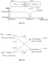
- the physical layer protocol works on a known slot boundary as shown in FIG. 13.
- FIG. 13 shows the detection of a start of a frame (slot).
- a new slot timing drift ⁇ 1310 for a frame m+1 1312 compared to a frame m 1314 can be measured and sent to the Low MAC for the slot synchronization tracking.
- the slot timing drift ⁇ is measured as the AGC is set at [-30 -7] dBFS as shown in FIG. 11 .
- the slot drift ⁇ can be sent to the Low MAC protocol.
- the preamble and CSI processing module 1014 can estimate a CFO.
- the receiver noise, w j (n) is assumed to be zero-mean white Gaussian with variance ⁇ n 2 and the signal variance is assumed to be ⁇ s 2 .
- IIR infinite impulse response
- the preamble and CSI processing module ( FIG. 10 , 1014) can also estimate CSI values.
- FIG. 14 illustrates the computation of H(k) values for two CSI fields.
- Each slot consists of Nrx 320-sample CSI fields in a MSA system.
- 64 GI samples are removed from the CSI fields at Inverse OFDM modules ( FIG. 10 , 1016).
- the CSI fields in the frequency domain can be recovered by taking a 256-point fast Fourier transform of the symbol.
- the data field of the received MSA slot can be processed.
- frequency tone fields 210, 212, 24 and CSI fields 216, 218 are followed by a data field 220, which includes 8 OFDM symbols.
- Each 64 ⁇ sec long OFDM symbol has 320 samples.
- the 64-symbol GI is removed first from each stream at the inverse OFDM blocks 1016.
- Nrx 256-point complex fast Fourier transforms are taken on each of the 256 complex time samples at the inverse OFDM blocks 116:
- Z ⁇ k ⁇ Z 1 k , Z 2 k ...
- Z N rx k ⁇ H k H 1,1 k H 1,2 k H 1 , N rx k H 2,1 k H 2,1 k H 2 , N rx k ⁇ H N tx ,1 k H N tx ,2 k H N tx , N rx k N tx ⁇ N rx
- a MIMO minimum mean squared error (“MMSE”) decoder 1018 can identify and recover several distinct signals transmitted on the same channel from several transmitters.
- the MMSE decoder 1018 uses the channel state information matrix in the decoding.
- the values generated by the MIMO decoder 1018 will include a large amount of error.
- the MSA system is a distributed MIMO system and the CSI H(k) includes two independent RF transmitter chains, so the possibility of a singular H(k) is small.
- the MIMO decoder 1018 recovers the Ntx streams as: X ⁇ ⁇ k X ⁇ 1 k X ⁇ 2 k ⁇ X ⁇ N tx k Phase error can be estimated and corrected by a phase lock loop ("PLL") 1020 based on the pilot tones.
- PLL phase lock loop
- Constellation demappers 1022 perform constellation demapping on the decoded bit streams.
- b j k ,2 4 42 ⁇
- b j k ,5 2 42 ⁇
- When Ntx> 1, soft bits are further weighted by: ⁇ b j k ,0 , b j k ,1 , b j k ,2 , b j k ,3 , b j k ,4 , b j k ,5 ⁇ ⁇ b j k ,0 , b
- the soft bit streams ⁇ b j (k, 0 ),b j (k, 1 ),b j (k, 2 ),b j (k, 3 ),b j (k, 4 ),b j (k, 5 ) ⁇ can be de-interleaved by Ntx De-interleavers 1024.
- the deinterleavers 1024 which perform the inverse of the function performed by the interleaver ( FIG. 7 , 714), can be defined by two permutations.
- the frequency deinterleaving can also be implemented by a LUT method.
- Ntx Viterbi decoders 1026 with trace back length of 64 can be used to decode the bit streams from the de-interleavers 1024.
- a de-scrambler 1028 can be used to descramble the OFDM symbols scrambled using the scrambler ( FIG. 7 , 710).
- a distributed MIMO system consists of a group of nodes at different locations and with different clock drifts.
- MSA time synchronization can be used to ensure that all of the nodes transmit at the same time such that transmissions from the distributed nodes can be treated as transmissions from one node passing through a multipath channel.
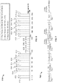
- FIG. 15 illustrates an algorithm 1500 for a node (referred to here as a synchronizing node or synch node) that has just joined the neighborhood of nodes to time synchronize to a reference node.
- the reference node is a node that is already operating on a correct slot mark 1510.
- the synch node is operating on an arbitrary slot mark 1512.
- the synch node receives a reference slot at the measured time T1 1514.
- the synch node slot mark is advanced to T d (min) 1516 from the received point, where T d (min) is the MSA minimum distance time (0.03 ⁇ sec).
- T d (min) is the MSA minimum distance time (0.03 ⁇ sec).
- the synch node now is operating on a new slot mark 1518.
- the synch node listens to the reference node for a second transmission.
- a short timing contention slot is a 128-sample complex tone field, such as two frequency tone fields.
- the short timing contention frequency tone is randomly selected from a list of unused tones.
- the short timing contention slot can only be detected and measured when there is only a short timing contention transmission in that slot.
- the reference node sends back the measurement T3 1524 to the synch node.
- T3(n) is a 9-bit unsigned integer that represents a maximum possible T3(n) of 51.2 ⁇ sec with 0.1 ⁇ sec resolution. Therefore a total T3 message consists of 9*N_node T3 bits and N_node ⁇ log 2 (N_node) node index bits. Slot timing adjustment should not be allowed before sending the T3 message.
- the synch node can determine the network frequency by measuring the carrier frequency offset a number of times (e.g., at least 20 times) adjusting its oscillator to match the network frequency before transmitting.
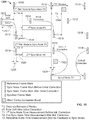
- the MSA nodes 1610 can be frequency synchronized in an isolated mesh network where two clusters 1612, 1614 are not in a communication range.
- the frequency synchronization algorithm can be configured to use a "lowest" frequency identification (“ID") value and propagate that information to neighboring nodes to get convergence on a frequency associated with the frequency ID value. For example, the first cluster 1612 chooses a frequency ID of 12 and the second cluster 1614 chooses a frequency ID of 3.
- a bridge node 1616 listens to nodes from both clusters 1612, 1614.
- the bridge node 161 chooses the frequency of the second cluster 1614 because the frequency ID is 3 which is lower than the frequency ID of 12 of the first cluster 1612.
- the bridge node 161 adjusts its transmit/receive frequency to the frequency associated with the frequency ID of 3.
- the nodes in the first cluster 1612 receive a signal from the bridge node 1616, they will change their frequency to the frequency associated with the frequency associated with the frequency ID value of 3.
- MSA network synchronization is a combined effort of time and frequency synchronization. There are two MSA synchronization modes: a newly joined synch node synchronizing to the network and a synched node tracking the timing of the network to remain synchronized.
- FIG. 17 shows a ladder diagram of a newly joined synch node synchronizing to a network.
- the new joined node is timing and frequency un-synched.
- the synch node receives a transmission from one of a set of reference nodes (the other nodes in the neighborhood) 1710.
- the synch node measures the time T1 that it received the transmission 1712.
- the synch node estimates a carrier frequency offset for the frame for frequency synchronization 1714 and performs an initial frame mark adjustment 1716.
- the synch node then receives a set of transmissions TX(1) - TX(N) from the reference nodes 1718 and measures and records the received timing T2(i,n) for M different nodes, where i is the node index and n is the frame number 1720.
- FIG. 18 shows a ladder diagram for a node in a tracking mode, where a synched node is tracking the timing of the network to remain synchronized. After the node has synched with the network, the timing and frequency are constantly changing due to frequency oscillator drift and movement of the node and other nodes. Therefore the timing and frequency are tracked continuously.
- a tracking node node that is tracking the network timing to remain synchronized receives a set of frames TX(1) through TX(N) transmitted from a set of reference nodes (other nodes in the neighborhood) 1810. The tracking node measures and records a received time T2(i,n) for M different nodes, where i is the node index and n is the frame number 1812.
- the tracking node measures carrier frequency offsets for each of the frames and calculates an average CFO for the N frames 1814 and adjusts its local oscillator based on the average CFO 1816.
- the Tracking node transmits a MSA frame to each of the reference nodes 1818.
- the MSA frame is received by L reference nodes 1820.
- Each reference node measures a received time t# for the MSA frame at a different time m and transmits to the Tracking node the T3(j,m) 1822.
- a node can operate on a high quality of service ("QoS") mode when its first tone in a tone group is set. The node can reserve the next slot to transmit.
- QoS quality of service
- N node can be estimated over an observation window of 64 slots. The number of active tones can be detected on the FTFs.
- the CSMA/CA MAC layer was simulated based on the following parameters:
- the MSA MAC layer was simulated using the following parameters:
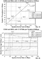
- FIG. 19 shows system throughput for a CSMA/CA system 1910, a two antenna MSA system 1912, a four antenna MSA system 1914, and a six antenna MSA system 1916 as a function of the system arrival rate.
- FIG. 20 shows average delay for the CSMA/CA system 2010, the two antenna MSA system 2012, the four antenna MSA system 2014, and the six antenna MSA system 2016 as a function of the system arrival rate.
- MSA and CSMA/CA were compared at their throughput tuning points 1918, 1920, 1922, 1924 shown in FIG. 19 .
- Table 7 lists the system throughput and delay at the turning points.
- the MSA throughput improvement is about Nss times compared with the CSMA.
- FIG. 21 shows a comparison of throughputs for eight node 2110 and 16 node 2112 CSMA/CA and four antenna MSA ("MSA-4") with eight nodes 2114 and 16 nodes 2116.
- the throughput at the turning points were unchanged with the number of nodes for both CSMA/CA and MSA4.
- MSA the active node number was known to each node so that each node could quickly adjust its transmission rate to achieve highest throughput.
- FIG. 22 shows delay performance for eight node 2210 and 16 node 2212 CSMA/CA and MSA4 with eight nodes 2214 and 16 nodes 2216.
- the CSMA/CA delay went from 2124 ⁇ sec down to 1598 ⁇ sec.
- the MSA-4 delay went from 384 ⁇ sec down to 142 ⁇ sec.
- each node achieved near full throughput (37 Mbps), as shown in FIG. 23 , with small delays as shown in FIG. 24 .
- MSA can significantly increase the system throughput with much smaller system delay as compared to CSMA/CA. MSA can quickly adapt to a dynamic wireless network. Moreover, MSA does not have the hidden node problem in a wireless network.
Landscapes
- Engineering & Computer Science (AREA)
- Computer Networks & Wireless Communication (AREA)
- Signal Processing (AREA)
- Mobile Radio Communication Systems (AREA)
- Radio Transmission System (AREA)
Claims (17)
- Verfahren, das Folgendes beinhaltet:Empfangen, an einem Synchronisationsknoten, eines ersten Referenz-Frame von einem ersten Referenzknoten zu einem ersten Zeitpunkt und Speichern eines ersten Frame-Timing-Wertes, der den ersten Zeitpunkt repräsentiert, gemäß einer anfänglichen Frame-Marke (1514);Berechnen einer neuen Frame-Marke durch Subtrahieren eines Mindestzeitwertes, der die Distanz vom Synchronisationsknoten zum ersten Referenzknoten repräsentiert, vom ersten Frame-Timing-Wert;Empfangen, am Synchronisationsknoten, eines zweiten Referenz-Frame vom ersten Referenzknoten zu einem zweiten Zeitpunkt und Speichern eines zweiten Frame-Timing-Wertes, der den zweiten Zeitpunkt repräsentiert, gemäß der berechneten neuen Frame-Marke (1520);Übertragen, vom Synchronisationsknoten zum ersten Referenzknoten, eines kurzen Timing-Konkurrenzzeit-Frame gemäß der berechneten neuen Frame-Marke (300, 1522);Empfangen, am Synchronisationsknoten vom ersten Referenzknoten, eines ersten Ankunftszeitwertes, der den Zeitpunkt (1524) repräsentiert, zu dem der erste Referenzknoten den kurzen Timing-Konkurrenz-Frame empfangen hat;Berechnen einer ersten Zeitabweichung (1526) vom ersten Ankunftszeitwert und vom zweiten Frame-Timing-Wert;Justieren der Frame-Marke auf der Basis der ersten Zeitabweichung (1528); undÜbertragen von Daten vom Synchronisationsknoten gemäß einem von der justierten Frame-Marke bestimmten Timing.
- Verfahren nach Anspruch 1, wobei das Berechnen der Zeitabweichung gemäß der folgenden Gleichung erfolgt:

- Verfahren nach Anspruch 1, das ferner Folgendes beinhaltet:Bestimmen einer Referenzfrequenz der Übertragung des zweiten Referenz-Frame; undJustieren eines Oszillators am Synchronisationsknoten auf der Basis der Referenzfrequenz.
- Verfahren nach Anspruch 1, das ferner Folgendes beinhaltet:Empfangen eines dritten Referenz-Frame von einem zweiten Referenzknoten zu einem dritten Zeitpunkt und Speichern eines dritten Frame-Timing-Wertes, der den dritten Zeitpunkt repräsentiert, gemäß der neuen Frame-Marke;Übertragen des kurzen Timing-Konkurrenz-Frame zum zweiten Referenzknoten gemäß der neuen Frame-Marke;Empfangen, am Synchronisationsknoten vom zweiten Referenzknoten, eines zweiten Ankunftszeitwertes, der den Zeitpunkt repräsentiert, zu dem der zweite Referenzknoten den kurzen Timing-Konkurrenz-Frame empfangen hat;Berechnen einer zweiten Zeitabweichung vom zweiten Ankunftszeitwert und dem dritten Frame-Timing-Wert;Bestimmen einer durchschnittlichen Zeitabweichung der ersten Zeitabweichung und der zweiten Zeitabweichung; undJustieren der Frame-Marke auf der Basis der durchschnittlichen Zeitabweichung.
- Verfahren nach Anspruch 4, das ferner Folgendes beinhaltet:Bestimmen eines ersten Referenzknoten-Trägerfrequenzversatzes vom zweiten Referenz-Frame;Bestimmen eines zweiten Referenzknoten-Trägerfrequenzversatzes vom dritten Referenz-Frame;Bestimmen eines durchschnittlichen Trägerfrequenzversatzes aus dem ersten Referenzknoten-Trägerfrequenzversatz und dem zweiten Referenzknoten-Trägerfrequenzversatz; undJustieren eines Oszillators am Sychronisationsknoten auf der Basis des durchschnittlichen Trägerfrequenzversatzes.
- Verfahren nach Anspruch 5, wobei das Bestimmen des ersten Referenzknoten-Trägerfrequenzversatzes das Analysieren von zwei Frequenztonfeldern im zweiten Referenz-Frame beinhaltet und das Bestimmen des zweiten Referenzknoten-Trägerfrequenzversatzes das Analysieren von zwei Frequenztonfeldern im dritten Referenz-Frame beinhaltet.
- Verfahren nach Anspruch 4, das ferner Folgendes beinhaltet:Empfangen, am Synchronisationsknoten, von einem oder mehreren Referenz-Frames von jeweils einem oder mehreren dritten Referenzknoten;Messen und Aufzeichnen von vierten Frame-Timing-Werten für jeden der ein oder mehreren Referenz-Frames von den ein oder mehreren dritten Referenzknoten, die die Ankunftszeiten der ein oder mehreren Referenz-Frames repräsentieren, von den jeweils ein oder mehreren dritten Referenzknoten gemäß der justierten Frame-Marke;Berechnen von Trägerfrequenzversatzwerten für jeden der ein oder mehreren Referenz-Frames von den jeweils ein oder mehreren dritten Referenzknoten;Bestimmen, auf der Basis der Trägerfrequenzversatzwerte für jeden der ein oder mehreren Referenz-Frames, eines durchschnittlichen Trägerfrequenzversatzwertes der ein oder mehreren Referenz-Frames von den jeweils ein oder mehreren dritten Referenzknoten;Justieren eines Lokaloszillators am Synchronisationsknoten auf der Basis des durchschnittlichen Trägerfrequenzversatzwertes;Übertragen eines kurzen Timing-Konkurrenz-Frame zu jedem der ein oder mehreren dritten Referenzknoten gemäß der justierten Frame-Marke und dem justierten Lokaloszillator;Empfangen von fünften Frame-Timing-Werten von den ein oder mehreren dritten Referenzknoten, die Ankunftszeitwerte von Zeitpunkten repräsentieren, zu denen die jeweils ein oder mehreren dritten Referenzknoten die kurzen Timing-Konkurrenz-Frames empfangen haben;Bestimmen einer dritten Zeitabweichung für die Ankunftszeitwerte, wobei die dritte Zeitabweichung für jeden der ein oder mehreren dritten Referenzknoten wie folgt ist:
 Bestimmen einer weiteren durchschnittlichen Zeitabweichung, wobei die weitere durchschnittliche Zeitabweichung ein Durchschnitt der dritten Zeitabweichungen von allen der ein oder mehreren dritten Referenzknoten ist;Justieren der Frame-Marke gemäß der weiteren durchschnittlichen Zeitabweichung; undÜbertragen von Daten vom Synchronisationsknoten-Frame gemäß der justierten Frame-Marke.
 - Verfahren nach Anspruch 7, das ferner Folgendes beinhaltet:
Berechnen, für jeden der ein oder mehreren Referenz-Frames, eines automatischen Verstärkungsregelungswertes anhand eines Frequenztonfeldes des Frame. - Verfahren nach Anspruch 8, wobei das Berechnen des automatischen Verstärkungsregelungswertes Folgendes beinhaltet:Einstellen des automatischen Verstärkungsregelungswertes auf einen Maximalwert;Vergleichen eines Empfangssignalstärkeindikators für den Frame mit einem ersten Schwellenwert;Verringern, wenn der Empfangssignalstärkeindikator größer ist als der erste Schwellenwert, des automatischen Verstärkungsregelungswertes um einen ersten vorbestimmten Betrag;Vergleichen des Empfangssignalstärkeindikators für den Frame mit einem zweiten Schwellenwert; undErhöhen, wenn der Empfangssignalstärkeindikator kleiner ist als der zweite Schwellenwert, des automatischen Verstärkungsregelungswertes um einen zweiten vorbestimmten Betrag.
- Verfahren nach Anspruch 7, das ferner Folgendes beinhaltet:Identifizieren eines mit einem der ein oder mehreren Referenz-Frames assoziierten Knotens durch Analysieren wenigstens eines Frequenztonfeldes des Referenz-Frame,wobei ein Frequenztonfeld eines Referenz-Frame einen zufällig ausgewählten komplexen Ton umfasst, undwobei das Analysieren Folgendes beinhaltet:Bestimmen einer Komplextonleistung durch Durchführen einer schnellen Fourier-Transformation an dem Frequenztonfeld;Berechnen einer Rauschleistung; undBestimmen eines Signal-Rausch-Verhältnisses der Komplextonleistung zur Rauschleistung.
- Verfahren nach Anspruch 10, das ferner Folgendes beinhaltet:Berechnen von Kanalzustandsinformationen für jeden Knoten durch Analysieren von Kanalzustandsinformationsfeldern der ein oder mehreren Referenz-Frames,wobei jeder Referenz-Frame ein jedem Knoten entsprechendes Kanalzustandsinformationsfeld beinhaltet, undwobei das Analysieren von Kanalzustandsinformationsfeldern das Durchführen einer schnellen Fourier-Transformation beinhaltet.
- Verfahren nach Anspruch 11, das ferner das Analysieren eines Datenfeldes des Referenz-Frame beinhaltet.
- Verfahren nach Anspruch 7, wobei das Berechnen der Trägerfrequenzversatzwerte für jeden der ein oder mehreren Referenz-Frames das Empfangen und Analysieren von zwei Präambeln beinhaltet.
- Verfahren nach Anspruch 13, wobei das Berechnen der Trägerfrequenzversatzwerte für jeden der ein oder mehreren Referenz-Frames das Analysieren von zwei Frequenztonfeldern der Präambeln beinhaltet.
- Verfahren nach Anspruch 7, das ferner Folgendes beinhaltet:
Schätzen, für jeden Knoten in einem Netzwerk einschließlich des Synchronisationsknotens, eines Phasenversatzes für eine Übertragung von jedem Nachbarknoten in dem Netzwerk. - Verfahren nach Anspruch 15, das ferner das Übertragen, von einem ersten der Knoten in dem Netzwerk zu jedem der anderen Knoten in dem Netzwerk, einer Schätzung der Phasenversätze der anderen Knoten in dem Netzwerk beinhaltet.
- Verfahren nach Anspruch 16, das ferner Folgendes beinhaltet:Bestimmen eines Indexes für jeden Knoten in dem Netzwerk durch Analysieren eines Frequenztonfeldes in einem von jedem Knoten empfangenen Signal, wobei der Index ein zufällig gewählter komplexer Ton ist; undBerechnen von Kanalzustandsinformationen für jeden der Knoten in dem Netzwerk.
Applications Claiming Priority (2)
| Application Number | Priority Date | Filing Date | Title |
|---|---|---|---|
| US2973508P | 2008-02-19 | 2008-02-19 | |
| PCT/US2009/034496 WO2009105524A1 (en) | 2008-02-19 | 2009-02-19 | Mimo slotted aloha (msa) system |
Publications (3)
| Publication Number | Publication Date |
|---|---|
| EP2245772A1 EP2245772A1 (de) | 2010-11-03 |
| EP2245772A4 EP2245772A4 (de) | 2016-06-22 |
| EP2245772B1 true EP2245772B1 (de) | 2019-04-10 |
Family
ID=40955101
Family Applications (1)
| Application Number | Title | Priority Date | Filing Date |
|---|---|---|---|
| EP09712005.9A Active EP2245772B1 (de) | 2008-02-19 | 2009-02-19 | Mimo slotted aloha (msa)-system |
Country Status (5)
| Country | Link |
|---|---|
| US (2) | US8553824B2 (de) |
| EP (1) | EP2245772B1 (de) |
| AU (1) | AU2009215558B2 (de) |
| CA (2) | CA2717591C (de) |
| WO (1) | WO2009105524A1 (de) |
Cited By (2)
| Publication number | Priority date | Publication date | Assignee | Title |
|---|---|---|---|---|
| US11190627B2 (en) * | 2016-03-15 | 2021-11-30 | Fraunhofer-Gesellschaft zur Förderung der angewandten Forschung e.V. | Telegram splitting for slotted ALOHA |
| US11309915B1 (en) | 2019-07-11 | 2022-04-19 | Arrowhead Center, Inc. | Efficient implementation of a threshold modified min-sum algorithm for low-density parity-check decoders |
Families Citing this family (33)
| Publication number | Priority date | Publication date | Assignee | Title |
|---|---|---|---|---|
| US8768245B2 (en) * | 2008-08-18 | 2014-07-01 | Agency For Science, Technology And Research | Cyclic prefix schemes |
| US8374297B2 (en) * | 2008-09-15 | 2013-02-12 | Intel Corporation | Circuit, controller and methods for dynamic estimation and cancellation of phase and gain imbalances in quadrature signal paths of a receiver |
| JP5347792B2 (ja) * | 2009-07-16 | 2013-11-20 | ソニー株式会社 | 信号処理装置、信号処理方法、及び、受信システム |
| US9853847B2 (en) * | 2009-12-30 | 2017-12-26 | Mediatek Inc. | Measurement and carrier group based optimization in wireless OFDM multi-carrier communication systems |
| US9363068B2 (en) | 2010-08-03 | 2016-06-07 | Intel Corporation | Vector processor having instruction set with sliding window non-linear convolutional function |
| US9882624B2 (en) * | 2010-09-29 | 2018-01-30 | Qualcomm, Incorporated | Systems and methods for communication of channel state information |
| US9813135B2 (en) | 2010-09-29 | 2017-11-07 | Qualcomm, Incorporated | Systems and methods for communication of channel state information |
| US10090982B2 (en) * | 2010-09-29 | 2018-10-02 | Qualcomm Incorporated | Systems and methods for communication of channel state information |
| US9831983B2 (en) | 2010-09-29 | 2017-11-28 | Qualcomm Incorporated | Systems, methods and apparatus for determining control field and modulation coding scheme information |
| US9602298B2 (en) | 2010-09-29 | 2017-03-21 | Qualcomm Incorporated | Methods and apparatuses for determining a type of control field |
| US9374193B2 (en) | 2010-09-29 | 2016-06-21 | Qualcomm Incorporated | Systems and methods for communication of channel state information |
| US9077498B2 (en) * | 2010-09-29 | 2015-07-07 | Qualcomm Incorporated | Systems and methods for communication of channel state information |
| US9806848B2 (en) | 2010-09-29 | 2017-10-31 | Qualcomm Incorporated | Systems, methods and apparatus for determining control field and modulation coding scheme information |
| US20130315323A1 (en) * | 2011-04-24 | 2013-11-28 | Broadcom Corporation | Traveling pilots within single user, multiple user, multiple access, and/or MIMO wireless communications |
| US9338757B2 (en) * | 2011-10-03 | 2016-05-10 | Texas Instruments Incorporated | Clock synchronization and centralized guard time provisioning |
| WO2013063440A1 (en) * | 2011-10-27 | 2013-05-02 | Lsi Corporation | Vector processor having instruction set with vector convolution funciton for fir filtering |
| RU2012102842A (ru) | 2012-01-27 | 2013-08-10 | ЭлЭсАй Корпорейшн | Инкрементное обнаружение преамбулы |
| US9209959B2 (en) * | 2012-03-26 | 2015-12-08 | Electronics And Telecommunications Research Institute | Method of frequency synchronization in distributed network |
| KR102065172B1 (ko) * | 2012-03-26 | 2020-01-13 | 한국전자통신연구원 | 분산 네트워크에서의 주파수 동기화 방법 |
| US9042903B2 (en) * | 2013-01-10 | 2015-05-26 | Qualcomm Incorporated | Methods and apparatus for efficient co-existence of macro and small cells |
| US9923595B2 (en) | 2013-04-17 | 2018-03-20 | Intel Corporation | Digital predistortion for dual-band power amplifiers |
| JP2014238357A (ja) * | 2013-06-10 | 2014-12-18 | ソニー株式会社 | 受信装置、時刻差算出方法、およびプログラム |
| CN103490842B (zh) * | 2013-09-26 | 2016-09-28 | 深圳市大疆创新科技有限公司 | 数据传输系统及方法 |
| US9112471B1 (en) * | 2014-03-19 | 2015-08-18 | Freescale Semiconductor, Inc. | Gain control system for wireless communication system |
| CN107736059B (zh) * | 2015-06-17 | 2021-02-09 | 瑞典爱立信有限公司 | 一种具有稀疏同步信号速率的系统中的信号检测方法 |
| CN105577312B (zh) * | 2016-01-19 | 2018-04-13 | 云南磊奥明科技有限公司 | 数据帧同步方法及装置 |
| US11197222B2 (en) | 2017-02-16 | 2021-12-07 | Texas Instruments Incorporated | Systems and methods to support node mobility in wireless networks |
| US10477500B2 (en) * | 2017-03-07 | 2019-11-12 | Itron Networked Solutions, Inc. | Time distribution scheme for wireless mesh networks |
| WO2018167984A1 (ja) * | 2017-03-17 | 2018-09-20 | 富士通株式会社 | 無線通信装置、無線通信システム、および送信タイミング調整方法 |
| US10397091B1 (en) * | 2018-09-17 | 2019-08-27 | Cisco Technology, Inc. | Optical safety and connections discovery |
| US11863359B1 (en) * | 2021-05-11 | 2024-01-02 | Amazon Technologies, Inc. | Subcarrier pre-equalization technology for frequency selective fading characteristics of wireless channels |
| CN115412446A (zh) * | 2022-08-10 | 2022-11-29 | 东莞职业技术学院 | 用于多跳虚拟mimo系统vaa间通信模型的设计方法 |
| CN116827502B (zh) * | 2023-06-21 | 2025-08-19 | 深圳北航新兴产业技术研究院 | 一种基于差分相位调制的无导频强化Slotted ALOHA大规模随机接入与传输方法 |
Family Cites Families (18)
| Publication number | Priority date | Publication date | Assignee | Title |
|---|---|---|---|---|
| US5648958A (en) | 1995-04-05 | 1997-07-15 | Gte Laboratories Incorporated | System and method for controlling access to a shared channel for cell transmission in shared media networks |
| US6052812A (en) * | 1998-01-07 | 2000-04-18 | Pocketscience, Inc. | Messaging communication protocol |
| US8363757B1 (en) * | 1999-10-12 | 2013-01-29 | Qualcomm Incorporated | Method and apparatus for eliminating the effects of frequency offsets in a digital communication system |
| US6748040B1 (en) * | 2000-11-09 | 2004-06-08 | Time Domain Corporation | Apparatus and method for effecting synchrony in a wireless communication system |
| US7072432B2 (en) * | 2002-07-05 | 2006-07-04 | Meshnetworks, Inc. | System and method for correcting the clock drift and maintaining the synchronization of low quality clocks in wireless networks |
| JP3717472B2 (ja) * | 2002-11-08 | 2005-11-16 | 松下電器産業株式会社 | 送信装置及び自動利得制御方法 |
| US7415044B2 (en) * | 2003-08-22 | 2008-08-19 | Telefonaktiebolaget Lm Ericsson (Publ) | Remote synchronization in packet-switched networks |
| US7239626B2 (en) * | 2004-06-30 | 2007-07-03 | Sharp Laboratories Of America, Inc. | System clock synchronization in an ad hoc and infrastructure wireless networks |
| JP5148275B2 (ja) | 2004-08-12 | 2013-02-20 | インターデイジタル テクノロジー コーポレーション | 無線通信媒体へのアクセスを制御するための方法およびシステム |
| US7177374B2 (en) * | 2005-06-17 | 2007-02-13 | Broadcom Corporation | Apparatus and method for sampling frequency offset estimation and correction in a wireless communication system |
| KR101197280B1 (ko) * | 2005-07-15 | 2012-11-05 | 삼성전자주식회사 | 타임 스탬프를 이용한 타임 동기 방법 및 장치 |
| US7773681B2 (en) * | 2005-08-05 | 2010-08-10 | Interdigital Technology Corporation | Method and apparatus for estimating signal-to-noise ratio, noise power, and signal power |
| US7583654B2 (en) * | 2005-12-28 | 2009-09-01 | Honeywell International Inc. | Sub-frame synchronized multiplexing |
| US8677002B2 (en) * | 2006-01-28 | 2014-03-18 | Blackfire Research Corp | Streaming media system and method |
| TW200803389A (en) * | 2006-06-20 | 2008-01-01 | Nxp Bv | Method and apparatus for estimating carrier frequency offset |
| JP5105834B2 (ja) * | 2006-11-17 | 2012-12-26 | キヤノン株式会社 | 制御装置及びその制御方法、通信装置及びその制御方法、通信システム、及び、プログラム |
| US20080232485A1 (en) * | 2007-03-21 | 2008-09-25 | Samsung Electronics Co., Ltd. | Method and system for improved power loading by steering and power loading the preamble in beamforming wireless communication systems |
| TW200935858A (en) * | 2007-10-23 | 2009-08-16 | Agency Science Tech & Res | Communication device and method for synchronisation |
-
2009
- 2009-02-19 CA CA2717591A patent/CA2717591C/en active Active
- 2009-02-19 EP EP09712005.9A patent/EP2245772B1/de active Active
- 2009-02-19 AU AU2009215558A patent/AU2009215558B2/en active Active
- 2009-02-19 WO PCT/US2009/034496 patent/WO2009105524A1/en not_active Ceased
- 2009-02-19 CA CA2942545A patent/CA2942545C/en active Active
- 2009-02-19 US US12/388,912 patent/US8553824B2/en active Active
-
2013
- 2013-09-18 US US14/029,966 patent/US9585111B2/en active Active
Non-Patent Citations (1)
| Title |
|---|
| RENTEL C H ET AL: "A clock-sampling mutual network time-synchronization algorithm for wireless ad hoc networks", WIRELESS COMMUNICATIONS AND NETWORKING CONFERENCE, 2005 IEEE NEW ORLEANS, LA, USA 13-17 MARCH 2005, PISCATAWAY, NJ, USA,IEEE, vol. 1, 13 March 2005 (2005-03-13), pages 638 - 644, XP010791238, ISBN: 978-0-7803-8966-3, DOI: 10.1109/WCNC.2005.1424575 * |
Cited By (4)
| Publication number | Priority date | Publication date | Assignee | Title |
|---|---|---|---|---|
| US11190627B2 (en) * | 2016-03-15 | 2021-11-30 | Fraunhofer-Gesellschaft zur Förderung der angewandten Forschung e.V. | Telegram splitting for slotted ALOHA |
| US11309915B1 (en) | 2019-07-11 | 2022-04-19 | Arrowhead Center, Inc. | Efficient implementation of a threshold modified min-sum algorithm for low-density parity-check decoders |
| US11962324B1 (en) | 2019-07-11 | 2024-04-16 | Arrowhead Center, Inc. | Threshold-based min-sum algorithm to lower the error floors of quantized low-density parity-check decoders |
| US12334954B1 (en) | 2019-07-11 | 2025-06-17 | Arrowhead Center, Inc. | Threshold-based min-sum algorithm to lower the error floors of quantized low-density parity-check decoders |
Also Published As
| Publication number | Publication date |
|---|---|
| US9585111B2 (en) | 2017-02-28 |
| CA2942545A1 (en) | 2009-08-27 |
| EP2245772A1 (de) | 2010-11-03 |
| US20090207954A1 (en) | 2009-08-20 |
| US20140016626A1 (en) | 2014-01-16 |
| CA2717591A1 (en) | 2009-08-27 |
| AU2009215558B2 (en) | 2014-03-06 |
| CA2717591C (en) | 2016-11-08 |
| AU2009215558A1 (en) | 2009-08-27 |
| CA2942545C (en) | 2017-05-30 |
| WO2009105524A1 (en) | 2009-08-27 |
| US8553824B2 (en) | 2013-10-08 |
| EP2245772A4 (de) | 2016-06-22 |
Similar Documents
| Publication | Publication Date | Title |
|---|---|---|
| EP2245772B1 (de) | Mimo slotted aloha (msa)-system | |
| US12432275B2 (en) | Communication format for a wireless network | |
| CN109565345B (zh) | 接收同步信号的方法及其装置 | |
| US10935664B2 (en) | Null data packet (NDP) announcement frame for NDP ranging | |
| EP1821477B1 (de) | Drahtlose Kommunikationsvorrichtung und drahtloses Kommunikationsverfahren | |
| US10165094B2 (en) | Structure for low-power-low-rate data transmission | |
| US8498350B2 (en) | Communication system incorporating physical layer waveform structure | |
| RU2379847C2 (ru) | Синхронизация хронирования и оценка канала при переходе между локальными и глобальными формами сигнала с использованием назначенного пилот-сигнала tdm | |
| US10158511B2 (en) | Systems and methods for wireless communication in sub gigahertz bands | |
| US20030210645A1 (en) | Estimating frequency offsets using pilot tones in an OFDM system | |
| WO2010145568A1 (en) | Method and apparatus for generating time-frequency patterns for reference signal in an ofdm wireless communication system | |
| US20190297622A1 (en) | Doppler mode in a wireless network | |
| KR20080007486A (ko) | 유효 신호 대 잡음비에 기초하여 직교 주파수 분할 다중화시스템의 타이밍 제어 | |
| US20130343433A1 (en) | Systems and methods for wireless communication in sub gigahertz bands | |
| WO2008000069A1 (en) | Methods and systems for transmit diversity | |
| JP4264550B2 (ja) | 受信装置並びにチャネル推定装置 | |
| US20220312418A1 (en) | Narrow-band internet of things physical random-access channel (nprach) receiver | |
| WO2015099804A1 (en) | Methods and arrangements to estimate carrier frequency offset | |
| AU2014200874B2 (en) | Mimo slotted aloha (msa) system | |
| US9008195B2 (en) | Detection of a packet type in a communications system | |
| WO2019137808A1 (en) | Time and frequency offset estimation using repeated data symbols | |
| CN121923966A (zh) | 信号处理方法、装置及计算机可读存储介质 | |
| Mohamed | Strategies and Implementations to Support MultipleWireless Protocols with a Single RF Front-end | |
| HK1107460A1 (en) | Method for generating preamble structures and signaling structures in a mimo-ofdm transmission system | |
| HK1107460B (en) | Method for generating preamble structures and signaling structures in a mimo-ofdm transmission system |
Legal Events
| Date | Code | Title | Description |
|---|---|---|---|
| PUAI | Public reference made under article 153(3) epc to a published international application that has entered the european phase |
Free format text: ORIGINAL CODE: 0009012 |
|
| 17P | Request for examination filed |
Effective date: 20100907 |
|
| AK | Designated contracting states |
Kind code of ref document: A1 Designated state(s): AT BE BG CH CY CZ DE DK EE ES FI FR GB GR HR HU IE IS IT LI LT LU LV MC MK MT NL NO PL PT RO SE SI SK TR |
|
| AX | Request for extension of the european patent |
Extension state: AL BA RS |
|
| DAX | Request for extension of the european patent (deleted) | ||
| RA4 | Supplementary search report drawn up and despatched (corrected) |
Effective date: 20160523 |
|
| RIC1 | Information provided on ipc code assigned before grant |
Ipc: H04L 27/26 20060101ALI20160517BHEP Ipc: H04J 3/06 20060101AFI20160517BHEP |
|
| STAA | Information on the status of an ep patent application or granted ep patent |
Free format text: STATUS: EXAMINATION IS IN PROGRESS |
|
| 17Q | First examination report despatched |
Effective date: 20180219 |
|
| RIC1 | Information provided on ipc code assigned before grant |
Ipc: H04W 56/00 20090101ALI20180716BHEP Ipc: H04J 3/06 20060101AFI20180716BHEP Ipc: H04L 27/26 20060101ALI20180716BHEP |
|
| GRAP | Despatch of communication of intention to grant a patent |
Free format text: ORIGINAL CODE: EPIDOSNIGR1 |
|
| STAA | Information on the status of an ep patent application or granted ep patent |
Free format text: STATUS: GRANT OF PATENT IS INTENDED |
|
| INTG | Intention to grant announced |
Effective date: 20180905 |
|
| GRAS | Grant fee paid |
Free format text: ORIGINAL CODE: EPIDOSNIGR3 |
|
| GRAA | (expected) grant |
Free format text: ORIGINAL CODE: 0009210 |
|
| STAA | Information on the status of an ep patent application or granted ep patent |
Free format text: STATUS: THE PATENT HAS BEEN GRANTED |
|
| AK | Designated contracting states |
Kind code of ref document: B1 Designated state(s): AT BE BG CH CY CZ DE DK EE ES FI FR GB GR HR HU IE IS IT LI LT LU LV MC MK MT NL NO PL PT RO SE SI SK TR |
|
| REG | Reference to a national code |
Ref country code: GB Ref legal event code: FG4D |
|
| REG | Reference to a national code |
Ref country code: CH Ref legal event code: EP Ref country code: AT Ref legal event code: REF Ref document number: 1120116 Country of ref document: AT Kind code of ref document: T Effective date: 20190415 |
|
| REG | Reference to a national code |
Ref country code: IE Ref legal event code: FG4D |
|
| REG | Reference to a national code |
Ref country code: DE Ref legal event code: R096 Ref document number: 602009057819 Country of ref document: DE |
|
| REG | Reference to a national code |
Ref country code: NL Ref legal event code: FP |
|
| REG | Reference to a national code |
Ref country code: LT Ref legal event code: MG4D |
|
| REG | Reference to a national code |
Ref country code: AT Ref legal event code: MK05 Ref document number: 1120116 Country of ref document: AT Kind code of ref document: T Effective date: 20190410 |
|
| PG25 | Lapsed in a contracting state [announced via postgrant information from national office to epo] |
Ref country code: ES Free format text: LAPSE BECAUSE OF FAILURE TO SUBMIT A TRANSLATION OF THE DESCRIPTION OR TO PAY THE FEE WITHIN THE PRESCRIBED TIME-LIMIT Effective date: 20190410 Ref country code: FI Free format text: LAPSE BECAUSE OF FAILURE TO SUBMIT A TRANSLATION OF THE DESCRIPTION OR TO PAY THE FEE WITHIN THE PRESCRIBED TIME-LIMIT Effective date: 20190410 Ref country code: LT Free format text: LAPSE BECAUSE OF FAILURE TO SUBMIT A TRANSLATION OF THE DESCRIPTION OR TO PAY THE FEE WITHIN THE PRESCRIBED TIME-LIMIT Effective date: 20190410 Ref country code: HR Free format text: LAPSE BECAUSE OF FAILURE TO SUBMIT A TRANSLATION OF THE DESCRIPTION OR TO PAY THE FEE WITHIN THE PRESCRIBED TIME-LIMIT Effective date: 20190410 Ref country code: PT Free format text: LAPSE BECAUSE OF FAILURE TO SUBMIT A TRANSLATION OF THE DESCRIPTION OR TO PAY THE FEE WITHIN THE PRESCRIBED TIME-LIMIT Effective date: 20190910 Ref country code: NO Free format text: LAPSE BECAUSE OF FAILURE TO SUBMIT A TRANSLATION OF THE DESCRIPTION OR TO PAY THE FEE WITHIN THE PRESCRIBED TIME-LIMIT Effective date: 20190710 Ref country code: SE Free format text: LAPSE BECAUSE OF FAILURE TO SUBMIT A TRANSLATION OF THE DESCRIPTION OR TO PAY THE FEE WITHIN THE PRESCRIBED TIME-LIMIT Effective date: 20190410 |
|
| PG25 | Lapsed in a contracting state [announced via postgrant information from national office to epo] |
Ref country code: LV Free format text: LAPSE BECAUSE OF FAILURE TO SUBMIT A TRANSLATION OF THE DESCRIPTION OR TO PAY THE FEE WITHIN THE PRESCRIBED TIME-LIMIT Effective date: 20190410 Ref country code: GR Free format text: LAPSE BECAUSE OF FAILURE TO SUBMIT A TRANSLATION OF THE DESCRIPTION OR TO PAY THE FEE WITHIN THE PRESCRIBED TIME-LIMIT Effective date: 20190711 Ref country code: PL Free format text: LAPSE BECAUSE OF FAILURE TO SUBMIT A TRANSLATION OF THE DESCRIPTION OR TO PAY THE FEE WITHIN THE PRESCRIBED TIME-LIMIT Effective date: 20190410 Ref country code: BG Free format text: LAPSE BECAUSE OF FAILURE TO SUBMIT A TRANSLATION OF THE DESCRIPTION OR TO PAY THE FEE WITHIN THE PRESCRIBED TIME-LIMIT Effective date: 20190710 |
|
| PG25 | Lapsed in a contracting state [announced via postgrant information from national office to epo] |
Ref country code: AT Free format text: LAPSE BECAUSE OF FAILURE TO SUBMIT A TRANSLATION OF THE DESCRIPTION OR TO PAY THE FEE WITHIN THE PRESCRIBED TIME-LIMIT Effective date: 20190410 Ref country code: IS Free format text: LAPSE BECAUSE OF FAILURE TO SUBMIT A TRANSLATION OF THE DESCRIPTION OR TO PAY THE FEE WITHIN THE PRESCRIBED TIME-LIMIT Effective date: 20190810 |
|
| REG | Reference to a national code |
Ref country code: DE Ref legal event code: R097 Ref document number: 602009057819 Country of ref document: DE |
|
| PG25 | Lapsed in a contracting state [announced via postgrant information from national office to epo] |
Ref country code: CZ Free format text: LAPSE BECAUSE OF FAILURE TO SUBMIT A TRANSLATION OF THE DESCRIPTION OR TO PAY THE FEE WITHIN THE PRESCRIBED TIME-LIMIT Effective date: 20190410 Ref country code: RO Free format text: LAPSE BECAUSE OF FAILURE TO SUBMIT A TRANSLATION OF THE DESCRIPTION OR TO PAY THE FEE WITHIN THE PRESCRIBED TIME-LIMIT Effective date: 20190410 Ref country code: EE Free format text: LAPSE BECAUSE OF FAILURE TO SUBMIT A TRANSLATION OF THE DESCRIPTION OR TO PAY THE FEE WITHIN THE PRESCRIBED TIME-LIMIT Effective date: 20190410 Ref country code: SK Free format text: LAPSE BECAUSE OF FAILURE TO SUBMIT A TRANSLATION OF THE DESCRIPTION OR TO PAY THE FEE WITHIN THE PRESCRIBED TIME-LIMIT Effective date: 20190410 Ref country code: DK Free format text: LAPSE BECAUSE OF FAILURE TO SUBMIT A TRANSLATION OF THE DESCRIPTION OR TO PAY THE FEE WITHIN THE PRESCRIBED TIME-LIMIT Effective date: 20190410 |
|
| PLBE | No opposition filed within time limit |
Free format text: ORIGINAL CODE: 0009261 |
|
| STAA | Information on the status of an ep patent application or granted ep patent |
Free format text: STATUS: NO OPPOSITION FILED WITHIN TIME LIMIT |
|
| 26N | No opposition filed |
Effective date: 20200113 |
|
| PG25 | Lapsed in a contracting state [announced via postgrant information from national office to epo] |
Ref country code: TR Free format text: LAPSE BECAUSE OF FAILURE TO SUBMIT A TRANSLATION OF THE DESCRIPTION OR TO PAY THE FEE WITHIN THE PRESCRIBED TIME-LIMIT Effective date: 20190410 |
|
| PG25 | Lapsed in a contracting state [announced via postgrant information from national office to epo] |
Ref country code: SI Free format text: LAPSE BECAUSE OF FAILURE TO SUBMIT A TRANSLATION OF THE DESCRIPTION OR TO PAY THE FEE WITHIN THE PRESCRIBED TIME-LIMIT Effective date: 20190410 |
|
| REG | Reference to a national code |
Ref country code: CH Ref legal event code: PL |
|
| PG25 | Lapsed in a contracting state [announced via postgrant information from national office to epo] |
Ref country code: LU Free format text: LAPSE BECAUSE OF NON-PAYMENT OF DUE FEES Effective date: 20200219 Ref country code: MC Free format text: LAPSE BECAUSE OF FAILURE TO SUBMIT A TRANSLATION OF THE DESCRIPTION OR TO PAY THE FEE WITHIN THE PRESCRIBED TIME-LIMIT Effective date: 20190410 |
|
| PG25 | Lapsed in a contracting state [announced via postgrant information from national office to epo] |
Ref country code: CH Free format text: LAPSE BECAUSE OF NON-PAYMENT OF DUE FEES Effective date: 20200229 Ref country code: LI Free format text: LAPSE BECAUSE OF NON-PAYMENT OF DUE FEES Effective date: 20200229 |
|
| PG25 | Lapsed in a contracting state [announced via postgrant information from national office to epo] |
Ref country code: IE Free format text: LAPSE BECAUSE OF NON-PAYMENT OF DUE FEES Effective date: 20200219 |
|
| REG | Reference to a national code |
Ref country code: DE Ref legal event code: R081 Ref document number: 602009057819 Country of ref document: DE Owner name: ELBIT SYSTEMS OF AMERICA, LLC, FORT WORTH, US Free format text: FORMER OWNER: INNOVATIVE CONCEPTS, INC., MCLEAN, VA., US |
|
| REG | Reference to a national code |
Ref country code: BE Ref legal event code: PD Owner name: ELBIT SYSTEMS OF AMERICA, LLC; US Free format text: DETAILS ASSIGNMENT: CHANGE OF OWNER(S), ASSIGNMENT; FORMER OWNER NAME: INNOVATIVE CONCEPTS, INCORPORATED Effective date: 20211230 |
|
| PG25 | Lapsed in a contracting state [announced via postgrant information from national office to epo] |
Ref country code: MT Free format text: LAPSE BECAUSE OF FAILURE TO SUBMIT A TRANSLATION OF THE DESCRIPTION OR TO PAY THE FEE WITHIN THE PRESCRIBED TIME-LIMIT Effective date: 20190410 Ref country code: CY Free format text: LAPSE BECAUSE OF FAILURE TO SUBMIT A TRANSLATION OF THE DESCRIPTION OR TO PAY THE FEE WITHIN THE PRESCRIBED TIME-LIMIT Effective date: 20190410 |
|
| REG | Reference to a national code |
Ref country code: GB Ref legal event code: 732E Free format text: REGISTERED BETWEEN 20220519 AND 20220525 |
|
| PG25 | Lapsed in a contracting state [announced via postgrant information from national office to epo] |
Ref country code: MK Free format text: LAPSE BECAUSE OF FAILURE TO SUBMIT A TRANSLATION OF THE DESCRIPTION OR TO PAY THE FEE WITHIN THE PRESCRIBED TIME-LIMIT Effective date: 20190410 |
|
| REG | Reference to a national code |
Ref country code: NL Ref legal event code: PD Owner name: EIBIT SYSTEMS OF AMERICA, LLC; US Free format text: DETAILS ASSIGNMENT: CHANGE OF OWNER(S), ASSIGNMENT; FORMER OWNER NAME: INNOVATIVE CONCEPTS, INCORPORATED Effective date: 20230111 |
|
| P01 | Opt-out of the competence of the unified patent court (upc) registered |
Effective date: 20230627 |
|
| PGFP | Annual fee paid to national office [announced via postgrant information from national office to epo] |
Ref country code: NL Payment date: 20260218 Year of fee payment: 18 |
|
| PGFP | Annual fee paid to national office [announced via postgrant information from national office to epo] |
Ref country code: GB Payment date: 20260218 Year of fee payment: 18 |
|
| PGFP | Annual fee paid to national office [announced via postgrant information from national office to epo] |
Ref country code: DE Payment date: 20260217 Year of fee payment: 18 |
|
| PGFP | Annual fee paid to national office [announced via postgrant information from national office to epo] |
Ref country code: BE Payment date: 20260223 Year of fee payment: 18 Ref country code: IT Payment date: 20260227 Year of fee payment: 18 |
|
| PGFP | Annual fee paid to national office [announced via postgrant information from national office to epo] |
Ref country code: FR Payment date: 20260219 Year of fee payment: 18 |