EP2245973A2 - Système de sous-construction pour bacs de douche et sols de douche - Google Patents
Système de sous-construction pour bacs de douche et sols de douche Download PDFInfo
- Publication number
- EP2245973A2 EP2245973A2 EP20100004271 EP10004271A EP2245973A2 EP 2245973 A2 EP2245973 A2 EP 2245973A2 EP 20100004271 EP20100004271 EP 20100004271 EP 10004271 A EP10004271 A EP 10004271A EP 2245973 A2 EP2245973 A2 EP 2245973A2
- Authority
- EP
- European Patent Office
- Prior art keywords
- support
- plate
- shower
- height
- support frame
- Prior art date
- Legal status (The legal status is an assumption and is not a legal conclusion. Google has not performed a legal analysis and makes no representation as to the accuracy of the status listed.)
- Granted
Links
Images


Classifications
-
- A—HUMAN NECESSITIES
- A47—FURNITURE; DOMESTIC ARTICLES OR APPLIANCES; COFFEE MILLS; SPICE MILLS; SUCTION CLEANERS IN GENERAL
- A47K—SANITARY EQUIPMENT; ACCESSORIES THEREFOR, e.g. TOILET ACCESSORIES
- A47K3/00—Baths; Showers; Appurtenances therefor
- A47K3/16—Devices for fastening baths to floors or walls; Adjustable bath feet ; Lining panels or attachments therefor
- A47K3/17—Adjustable bath feet
-
- A—HUMAN NECESSITIES
- A47—FURNITURE; DOMESTIC ARTICLES OR APPLIANCES; COFFEE MILLS; SPICE MILLS; SUCTION CLEANERS IN GENERAL
- A47K—SANITARY EQUIPMENT; ACCESSORIES THEREFOR, e.g. TOILET ACCESSORIES
- A47K3/00—Baths; Showers; Appurtenances therefor
- A47K3/28—Showers or bathing douches
- A47K3/40—Pans or trays
Definitions
- the present invention relates to a substructure system, as it finds use in the sanitary sector.
- Bathtubs and especially shower trays or even shower trays for example, floor-level showers are set for example on a support frame.
- This support frame allows a suitable setting of the shower floor to be tiled later, at the same time facilitated installation and adaptation of the drain or siphon.
- the different materials that are used in conventional substructure systems have different material densities and properties, especially in terms of moisture absorption and expansion coefficient under changing temperature conditions. These different material densities or the different temperature properties in turn cause a different shrinkage behavior, what plates and Joint damage or leaks may result.
- Another disadvantage is the fact that the known substructure systems no longer allow subsequent leakage control of the drain or siphon, either directly after completion of assembly, or later during operation. After the previously described laying or casting of a gradient concrete or the compaction of the underbody granules, the drain or the siphon are no longer accessible.
- a further disadvantage is that the concrete, the mortar and the granule binder require drying times, postpone the follow-up work and overall represent an extension compared to modern dry construction with short construction periods and minimized execution risk according to current professional knowledge and expected professional responsibility.
- floor-level showers are also realized with shower floor elements.
- These shower floor elements are predominantly foam boards with an integrated slope, which are coated with a Dichtschlämme and reinforced with a mesh fabric fleece.
- the required installation height or required on a case-by-case basis is achieved by means of additional plate supports or by under-filling with different materials.
- the installation of the drainage system takes place before the shower floor element is set.
- the drainage channel or a drainage housing or siphon is connected via a socket, pluggable or screwed.
- Foam boards are also not stable against mechanical stresses and are subject in new condition as well as with the aging of a sometimes considerable shrinkage, which in turn can cause plate and joint damage.
- the height adjustment of the upper edge of the shower floor element to the upper edge of the underlay floor or screed is cumbersome and time-consuming in the known substructure systems. It takes place by placing additional foam boards of variable thicknesses or by underfilling with granules, sand or similar. A high level of effort once achieved can hardly be corrected afterwards, which is necessary, for example, when renovating ceramic floor tiles or tiles of a different thickness than previously used.
- the open-cell foam structure does not allow the installation of inspection openings.
- the cutting of recesses or generally a subsequent, mechanical processing is not possible, because this would damage the reinforcement or the encapsulation of the foam sheets.
- the foam boards are thus made in advance according to the predetermined fixed dimensions.
- the gutter or the drain housing must be installed before laying the shower floor element in this or parts thereof.
- the siphon and the drain pipe are mandatory before positioning the shower floor element mass to position and secure against displacement.
- the prior art also discloses combinations of support frame with shower floor elements, in which the support frame is height adjustable by means of threaded legs.
- the support frame is height adjustable by means of threaded legs.
- the installation of the support frame on which after setting the previously measured height rate, the shower floor element is placed.
- the connection of the water outlet via the shower channel and the drain body is again via a sleeve.
- the installation height of floor-level showers depends on the height of the base or screed and usually varies between 40 and 300 mm. Covering this entire 260 mm adjustment span may not always be guaranteed by the roots or at least not economical so it may be disadvantageous to have to provide thread roots that match the specific local conditions. In addition, this circumstance represents a possible source of error.
- the gutter or drain housing must be installed before laying the shower floor element in this.
- the water-conducting connection of the drainage channel and the drainage housing to the siphon is also again via a sleeve.
- the siphon and the drain pipe are to be positioned accurately before laying the shower floor element and secured against displacement.
- the object of the present invention is to provide a substructure system which largely avoids the disadvantages described above and is optimized with respect to its later properties in the assembled operating state, but also with regard to its mountability.
- the solution of the problem consists initially in the arrangement of a substructure system of a height-adjustable support frame and a support plate having at least one mounting or inspection opening.
- This mounting or inspection opening in the support plate is approximately centrally arranged or offset to its edge and designed and dimensioned so that when mounting, with already aufgoriter or pre-mounted support plate, the height of the upper edge of the support plate to the height of the upper edge the subfloor floor or screed or finished floor can be adjusted flush.
- This is inventively ensured by the elements, with where the height is adjustable - for example, with threaded feet - are accessible when the support plate by the mounting or inspection opening. This provides the significant advantage that no previous measurements and any trial grounds the support plate must be made. In addition, tightness checks on the drainage system are feasible, both during assembly and during later operation.
- the support plate can optionally itself represent the shower floor plate to be tiled later on, or a separate shower floor panel can be placed on it and fixed, which can be adapted in the same way to the height of the upper edge of the underlay floor or screed or finished floor.
- a further embodiment variant according to the invention provides that the support frame is integrated in the support plate, which at the same time is the uppermost shower floor panel or in the support panel on which a separate shower floor panel is still placed. This means that it is dispensed with a separate frame construction and the support plate or the shower base plate itself forms the frame on which the elements are arranged, with which the height is adjustable, or other inventive fastening and positioning elements, which in the following to be discribed.
- the support plate or the shower base plate preferably has an underside, which is designed plan and corresponds in the mounted state of the horizontal.
- the top of the support plate or the shower bottom plate is preferably provided with at least one surface which is at an angle to the horizontal.
- a single surface forms an inclined plane at which the water drains into a laterally arranged shower channel or into a drain housing.
- two surfaces can run toward an approximately centrally placed shower channel or a drainage housing or, for example, four surfaces for an approximately centered or also to an eccentrically arranged outflow. These surfaces can have congruent or different basic shapes.
- Another possible embodiment variant forms the described Gesocils Siegen in the shower tray plate itself, whether it is the support device consists of a preferably in this case, planning support plate and an attached shower floor plate or only a shower base plate.
- a further embodiment variant of the support plate or the shower base plate provides a normal, uniformly strong plate, which, however, is inclined as a whole by means of different heights-preferably integrated into the support plate or shower base plate.
- This embodiment variant or even one in which the underside of the support plate or the shower base plate forms at least two inclined surfaces, so that the cross section of the support plate tapers approximately in the middle, may be advantageous in terms of a free arrangement of the drainage system.
- support plate or the shower base plate described so far reveal a bottom lying in the mounted state or at least supports which form horizontal support surfaces in the mounted state.
- embodiments of support plates or shower base plates are hereby disclosed, in which the underside or the bearing surfaces are inclined or concave and thereby result in more extensive and more powerful adjustment options, for example with threaded feet, preferably both at its lower, and at its upper End in ball joints stand.
- a cost-effective variant of a substructure system is well feasible, in which only a single fall direction is provided towards a laterally arranged shower channel or a laterally arranged drain housing.
- the fact that the ball joints exert lateral support of the support plate or the shower base plate, a common, double-sided plate, without integrated slope, can be raised or raised on one side.
- the same effect can also be achieved with threaded sockets or holders for the thread legs, which provide the desired Inclined angle from the outset. This means that the thread roots are inclined at a horizontal position of the support plate or the shower base plate.
- the inventive support device preferably has a plurality of height adjustments or novel thread roots, which are each height adjustable with an endless threaded rod.
- the endless threaded rods are in shoes or relatively flat buffer discs, which are preferably made of a soft and little sound-transmitting material - for example made of rubber.
- the endless threaded rod is preferably mounted with a ball joint in the shoe, so that rotations of the endless threaded rod are not stopped early by a contact friction of the shoe on the concrete.
- it is equipped with a square g..einer key holder.
- the key receptacle can in principle also be arranged on the upper head of the endless threaded rod, for example, for an Allen key or Torx key and be accessible by a correspondingly positioned mounting hole in the support plate and / or the shower base plate.
- these so-called endless threaded rods are in contrast to arrangements from the prior art the decisive advantage that they serve a much larger setting height.
- the arrangements according to the prior art disclose a threaded rod, which is fastened with its upper end fixed below the desired support point in the support frame and thus results in a height adjustment, which alone results from how far a threaded root can be screwed down from the fixed threaded rod, without the thread root becomes unstable.
- the maximum Aufschraubmass can be at best equal to the total height of the neck of the threaded foot minus the height of a threaded nut.
- the height adjustability of a support frame according to the invention is realized differently insofar as on the one hand the (endless) threaded rod is arranged offset next to the support surface of the support frame or the support device and on the other hand projects clearly beyond the support frame or support device in their overall length.
- a threaded foot is rotated with a nut on a fixed threaded rod, but the (endless) threaded rod in a fixed nut arranged. Or in a thread, that is cut directly into a hole in the holder.
- At the lower end of the endless threaded rod according to the present invention in accordance with the state of the art, there is a bolt-on base foot which, however, remains screwed in at maximum and does not serve to adjust the height.
- the base foot can therefore be designed significantly flatter than a buffer disk.
- the upper attachment point or rather force application point of the thread root according to the invention is no longer located on the upper head of the threaded rod, but in an L-shaped holder or in a fixedly arranged on this holder nut.
- the upper force application point of the thread root according to the invention thus moves through rotations of the endless threaded rod over its entire length.
- the inventive height adjustment is thus characterized by a much greater adjustability with higher stability, because only by the laying of the upper force application point in the fixed nut on the holder (and no longer arranged in the thread root itself mother) only two force application points occur ,
- the upper force application point is the nut itself or the holder and the lower force application point is the lower end of the endless threaded rod.
- the endless threaded rod After setting the required height, the endless threaded rod can be detected with a lock nut to the fixed nut or threaded hole become. Subsequently, the protruding length of the endless threaded rod is cut with a cutting disc or special pliers.
- the endless threaded rods are preferably available from the outset in a length with which an adjustment height for the maximum usual underlay floor or screed thicknesses or more is guaranteed. A replacement or even a subsequent delivery of threaded rods, even with underlay floor or screed strengths, which are the usual maximum, is therefore excluded from the outset.
- the endless threaded rod is preferably made of a plastic which has a low sound transmission, in any case a lower than steel.
- the plastic of the endless threaded rods is preferably glass or carbon fiber reinforced.
- the endless threaded rod is, as already described above, arranged in the direction of its upper end in a holder which is attached to the support frame or the support device, for example, by being welded, screwed or glued.
- the holder can be arranged both on the support frame, but also on the support plate or on the shower base plate.
- the holder is screwed for receiving the endless threaded rod in a fixedly arranged nut, a so-called rivet nut or a press-fitted threaded sleeve or even in a threaded hole.
- This holder is designed according to the invention L-shaped, so that a leg of the Ls on a vertical surface of the support frame or the support plate or the shower base plate can be fastened.
- the other leg of the Ls can optionally be placed flush with the upper edge of the support frame or the upper edge of the support plate or the upper edge of the shower base plate or flush with the lower edge of the support frame or the lower edge of the support plate or the lower edge of the shower base plate.
- Different thicknesses of support plates can be placed on the holder. Also particularly thin, which are economical with the expensive material from which they are made, preferably additionally with recessed bearing surfaces or blind holes or recesses.
- the holder is formed almost double L-shaped as two connected to a web Ls.
- a mounting plate which is formed of four Ls and a connecting web.
- the four Ls may also be formed into one or more round walls.
- C-profile rails are possible as a bar support.
- This web support can, like the previously described L-shaped bracket also be attached to the support frame, or even directly to the support plate or the shower base plate by being screwed or preferably glued. In the case of a bond, the adhesive surfaces of the web support are preferably equipped with holes for a better contact of the adhesive.
- This web support provides an approximately centered on the web fixed or fixable arranged mother, a so-called rivet nut or a press-fitted threaded sleeve or at least one threaded hole, in which, as before, the endless threaded rod can be screwed.
- the force application points thus come, in contrast to the above-described L-shaped bracket in the direct extension of the supporting force occurring for the support frame, the support plate or the shower base plate to lie.
- these embodiments of a height adjustment according to the invention are further provided according to the invention with a mounting hole, which is arranged depending on the arrangement in the support frame, the support plate or the shower base plate approximately concentric with the longitudinal axis of the endless threaded rod.
- the endless threaded rod can be rotated, preferably by means of a Tool holder for a square or Allen key or Torx key.
- the height of the support device to the desired level is adjustable, or depending on the height of the upper edge of the support plate or the height of the upper edge of the shower base plate by at least three, preferably four such height adjustments are set to the same height level.
- the mounting hole can be sealed with a stopper, especially in those embodiment variant in which the last-described height adjustments are placed directly on the shower base plate.
- a still further embodiment variant of a height adjustment - both the height adjustment with the L-shaped bracket, as well as the last described with the web holder - provides a higher level of height adjustability by the endless threaded rod is arranged in a threaded sleeve.
- This threaded sleeve has an external thread which can be screwed into the threaded hole or the nut on the respective holder.
- this threaded sleeve also has a preferably continuous longitudinal bore with internal thread into which the endless threaded rod can be screwed. Due to the length addition of the so usable thread lengths creates a higher adjustability than only by the endless threaded rod alone.
- the threaded sleeve can preferably be secured with lock nuts on the external thread in both directions of screwing and also the endless threaded rod can preferably be fixed with a lock nut on the lower end side of the threaded sleeve. Equally, however, a lock nut on the upper end side of the threaded sleeve is possible or else a so-called grub screw, which is screwed from above into the internal thread of the threaded sleeve and thus fixes the endless threaded rod in the desired height position.
- a still further embodiment variant of the last-described height adjustment with an endless threaded rod in a threaded sleeve pursues an additional optimization of the sound decoupling.
- the bore for receiving the threaded sleeve in the L-shaped bracket or the web support has a larger diameter than the outer diameter of the external thread of the threaded sleeve. The latter is thus simply inserted into the bore and fixed with at least one nut at the top of the bore and at least one nut at the bottom of the bore.
- the nuts are here preferably each with a disc and another disc of a damping material (for example, rubber) underlaid.
- the threaded sleeve may instead of one of the two nuts, which flanged to the web support, also form a fixed collar, which is preferably formed at the upper end of the threaded sleeve.
- This fixed collar can preferably be inserted into the bar holder, again preferably in a receptacle, which no longer allows a positive rotation of the threaded sleeve and thus the remaining nut can be tightened.
- no positive reception can produce a possible sound bridge between the threaded sleeve and the web support by the fixed collar of the threaded sleeve can not get into direct contact with the inner walls of the web support.
- a key receptacle is preferably arranged on the outer diameter of the threaded sleeve.
- This key receptacle is preferably smaller than the outer diameter of the threaded sleeve or smaller than the external thread of the threaded sleeve and narrower than the nut is high. This allows the nut to be screwed seamlessly over the key holder.
- the support frame according to the invention consists of several support frame elements which are screwed together. According to one possible basic form of a support frame according to the invention, it forms a square or other basic geometric shapes whose sides each consist of a support frame element.
- One possible embodiment variant of this basic form provides for a web or a bridge on at least one side of the support frame.
- a support frame element which has hitherto formed one side of the square, now consists of two shorter support frame elements, which are connected to an overlying further support frame element.
- the web or the bridge thus forms a recess into which the drain housing or the siphon fits to save space.
- the support frame optionally has additional support frame elements, which are arranged in addition to the support frame elements described so far, fixed or preferably also pivotally mounted on a hinge. At least one such pivotally mounted support frame element fulfills the function of an additional, central stabilization of the applied support plate or shower base plate. However, the pivotally arranged support frame element also fulfills the function of an additional support or lay-on point for the support plate or the shower base plate, which is advantageously positioned arbitrarily within its pivot radius.
- a further embodiment variant of the support frame connects at least a part of the support frame elements or all supporting frame elements with joints. In this way, any basic shapes - depending on the design of the floor plan of the shower - realized.
- the inventive support frame further comprises at least one adjustment element.
- a length adjustment is at least between two support frame elements realized by, for example, a threaded bolt with left-hand thread at one end and right-hand thread at another end in corresponding internal threads of the support frame elements connected so rotatable.
- this length adjustment is also feasible with slots or telescoping spacers, which are preferably fixed with screw fasteners.
- This adjustment is used for position corrections of the support frame, after the support plate has been placed, preferably in particular in the direction of a vertical connection wall for the shower cubicle, be it just to this connection wall or away from her.
- the inventive substructure system has at least one adjustable and fixable support bracket.
- This support bracket is preferably formed so that it is secured with an adjustable rail, for example on a horizontal bottom or top of the support frame.
- the support bracket can also be optionally attached to the support plate or to the shower base plate as a displaceable and fixable positioning plate.
- shifts of the support bracket in the rail to the outside can be achieved so that a support surface of the support bracket on the side Demarcation surfaces of the underlay floor or screed or a wall abuts, then fixed and so a lateral fixation of the entire support frame is guaranteed in the underlay floor or screed.
- the support surface of the support bracket is preferably glued or lined with a sound-insulating material.
- the support bracket can optionally also be arranged on a vertical inside of the support frame or on a vertical edge or a vertical side of the support plate or on a vertical edge or on a vertical side of the shower base plate and thus with a contact of the support surface at the bottom of the local concrete a fixation of Reach supporting frame against lateral displacement.
- the lateral support surfaces of the support brackets may further be designed according to the invention as a guide or fastening member which can be inserted into a guide and support rail of a formwork panel. This makes it possible to first place the support frame or - depending on the arrangement of the support bracket - the support plate or the shower base plate on the subfloor, insert the formwork panels and now pour only the underlay floor or the screed at the desired height.
- the support brackets can optionally also have a guide surface for inserting the support plate or the support plate and the shower floor plate or the shower base plate.
- the support brackets are used only during assembly or when placing the support plate or when placing the support plate and the subsequent placing the shower base plate.
- the support brackets thus avoid only a displacement of the support frame, which can occur during installation by placing the support plate or the support plate and the shower base plate or the shower base plate by the support brackets after the successful positioning of the support plate or the support plate and the shower floor plate or the shower floor plate can be removed again.
- the support brackets even if their support surfaces are covered with a sound-insulating material or lined, but can be weak sound bridges between the support frame or - depending on the mounting location of the support brackets - the support plate or the shower base plate and the local concrete.
- removal of the support brackets can be done by unscrewing, which is made by the mounting or inspection opening.
- unscrewing which is made by the mounting or inspection opening.
- the fitter can knock out a cone holding the support bracket from a receptacle holding the cone with a hammer blow.
- the support device according to the invention furthermore has a laying device.
- at least one support plate is arranged on the support frame or on the support plate or on the shower floor plate, which is placed when setting the support device on the upper edge of the (in this case already finished cast) underlay floor or screed. In this way it is achieved that the upper edge of the underlay floor or screed is taken directly as a reference measure, without having to approach this measure with measurements.
- the laying device further comprises according to the invention a spacer which may be provided in a fixed length, for example, the thickness of the support plate or the shower base plate - in the event that the top of the support plate is the shower floor or the top of the shower floor plate to be tiled shower floor.
- the length of the spacer preferably corresponds to the sum of the thickness of the support plate and the thickness of the shower base plate.
- the spacer is configured optionally adjustable by, for example, consists of two parts which are screwed into one another or lockable sliding. By an appropriate length selection of the spacers or their length adjustment can, regardless of which reference measure is assumed, any final dimension for the height of the support device can be achieved. (Thus, for example, the support plate can also be placed on an already tiled finished floor surrounding the shower cubicle to be constructed.)
- the laying plate of the laying device is optionally designed so that it also allows attachment to a vertical end wall or wall. This installation situation is particularly present when a single shower cubicle is built, which is enclosed on three sides with walls.
- the support plate and / or the shower base plate according to the invention are made of a hard material.
- the hard material is preferably a recycling material, for example polyurethane granules, plastic granules, mineral granules, wood pulp granules and the like, which are glued or pressed with a water-insoluble binder.
- the material is thus insensitive to moisture, permanently dimensionally stable, mechanically machinable and preferably mixed with additives that have an antimycotic and antibacterial effect.
- the support plate and / or the shower floor plate have integrated recesses for the setting of shower channels or drain housings. These recesses can advantageously due to the good mechanical workability of the material even during installation at the site can be generated as needed.
- the support plate and / or the shower base plate may be formed one or more parts. They preferably have edge seams or, by milling, reduced edge thicknesses, so that lateral stability and a minimized installation height are guaranteed.
- the support plate or the shower base plate is preferably equipped with blind holes into which the threaded rods and nuts fit when hanging up.
- These blind holes also increase the adjustability to some extent, which still provides a sufficiently tight fit, but they primarily serve to conceal an upper end of the threaded rods and seated lock nuts. All configuration variants have in common that the upper end of the threaded rod remains (even after a possible cut off an excess length) above the support surface of the holder, on which the support plate or the shower base plate is placed.
- the support plate and / or the shower base plate can have prefabricated one-sided or multi-sided gradient formations, depending on the design and position of the drainage system.
- the support plate and / or the shower base plate may be partially preassembled so that only adaptation work is necessary at the site.
- the support plate and / or the shower base plate can not only consist of a single plate, but of two or more parts. For example, a part can already be pre-assembled - and connections for the shower channel or drainage system be preassembled at the factory - and only one application of another part of the support plate and / or the shower base plate may be required on site.
- a preferred embodiment variant of a multi-part support plate or shower floor plate provides a part which preferably comprises a preassembled drainage system.
- This drainage plate part simultaneously provides a positively or negatively shaped stepped connection edge with a support surface for another part of the support plate or shower base plate.
- This latter lay-up plate part of the support plate or shower base plate in turn has a correspondingly negative or positively shaped stepped connection edge with a corresponding support surface, so that a positive connection is possible.
- the bearing surfaces of the supporting drainage plate part and the laying-on plate part are preferably shaped so stable that no thread roots are necessary at the connecting edge of the laying plate part, because the roots of the supporting drainage plate part and the bearing surface take over the support of the lay-up plate part.
- the lay-up plate part is designed as a supporting plate and the drainage plate part is placed.
- the drainage system - be it in the form of a drainage housing or in the form of a drainage channel - is pre-assembled at the factory in a sealed and fixed manner.
- grooves and springs can also be provided, which in addition positively connect the drainage plate part and the lay-up plate part with each other.
- the grooves and springs may be formed to provide space and corresponding contact surfaces for the sealant or adhesive.
- the last-described attachment mode is also preferred for a cover plate for the mounting or inspection opening.
- the substructure system according to the invention is particularly suitable for floor-level showers; However, with appropriate, familiar to a skilled adaptations or appropriately sized brackets, however, equally suitable as a base system for shower trays or for bathtubs or for whirlpool bathtubs.
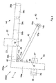
- the Fig. 1a shows a schematic and sectional view of a height adjustment 1, as it is known from substructure systems according to the prior art and is part of a support device 300a.
- a support frame 2 which has a bearing surface 3 with an insulating material 4 (for example, foam or rubber) for a plate 26, a threaded rod 5 is fixed fixed.
- a threaded foot 6 with a nut 9 is rotatably arranged.
- the threaded root 6 has a threaded neck 10 and a threaded base 7, on which an insulating piece 8 (for example, foam or rubber) is arranged.
- the height adjustment 1 in its lowest height position h1, because the threaded rod 5 with her bottom end abuts the top of the threaded foot socket 7 and thus no further rotation of the height adjustment 1 allowed.
- the lowest height position h1 is determined by an operative length 1 of the threaded rod 5 plus a base thickness S, wherein the thickness of the Dämm Anlagenes 8 is to be neglected in this case.
- the Fig. 1b shows the in Fig. 1a illustrated height adjustment 1 in a highest position h2, which is defined by the operative length 1 of the threaded rod 5 plus the base thickness S plus a Aufschraubmass A.
- the Aufschraubmass A can not exceed a position of the threaded rod 5 in favor of a remaining support function of the threaded foot 6, in which the threaded rod 5 is just in the nut 9.
- An entire adjustment height VH of the height adjustment 1 thus results from the highest height position h2 minus the lowest height position h1.
- the in this Fig. 1b illustrated highest height position h2 illustrates that force application points 11a, 11b and 11c are far away from each other and the threaded leg arrangement or the height adjustment 1 according to the prior art is laterally unstable.
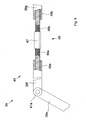
- the Fig. 2a shows, according to the lowest height position of the height adjustment 1 according to the prior art Fig. 1a , a lowest height position h1 'of an inventive adjusting device 200, which is part of a support device 300b according to the invention.
- a holder 12 is fixedly arranged, for example, by being screwed or welded to the support frame 2.
- the holder 12 is L-shaped and has at an approximately horizontal leg a receptacle or bore 13 with thread or optionally a fixed nut or a likewise fixedly arranged threaded sleeve through which an endless threaded rod 14 with a longitudinal axis 68 out is.
- An adjustment height JH corresponds to this inventive Adjusting device 200 advantageously almost the entire total length L of the endless threaded rod 14, which can be chosen arbitrarily long basically.
- the buffer disc 16 is preferably made of a defined soft plastic or rubber, in which the threaded socket 15 is firmly cast or screwed.
- the endless threaded rod 14 according to an optional embodiment variant in the fixed position in the buffer disk 16 is rotatable. This rotation can be realized by the endless threaded rod 14 forms at its lower end a ball head, which is inserted into a ball socket, or by the illustrated threaded socket 15 is mounted in a ball bearing.
- the Fig. 2b shows the inventive adjusting device 200 from Fig. 2a in its highest height position h2 '.
- FIGS. 2a and 2b show that the L-shaped bracket 12 at the top of the horizontal leg forms a support surface 3a for a support plate or a shower floor plate.
- This support surface 3a is always, ie both in the height adjustment, as well as after adjusting the height after cutting an excess length of the endless threaded rod 14 below an upper end 66 of the endless threaded rod 14.
- the top of the support frame 2 may represent an additional support surface.
- the support plate or the shower base plate preferably has a blind hole, not shown here, into which the upper end 66 of the threaded rod 14 and the lock nut 17 fit.
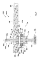
- FIG. 3 is the adjusting device 200 from the FIGS. 2a and 2b in an inventive support device 300c and an inventive substructure system 100 shown integrated.
- the substructure system 100 is shown in a cutaway detailed view in the installed state in a recess 19 which is formed by the local concrete 18 and a screed 20.
- An installation height EH has been achieved by placing the substructure system 100 with a laying device 22 according to the invention onto an upper edge height OH of an upper edge 21 of the screed 20. Subsequently is by rotations of the endless threaded rod 14, the substructure system 100 has been adjusted so that the buffer disk 16 comes to rest on the local concrete 18.
- the laying device 22 comprises a laying plate 23 and a screw 24, with which the laying plate 23, spaced by a spacer 25, is secured to the support frame 2.
- the height of the spacer 25 corresponds to an abutment edge 31 of a shower base plate 50 which is formed by a flat support surface 3b of the shower base plate 50 (which rests on a support surface 3c of the holder 12) and a shower base plate top 52 and here - as an optional design variant - tapered with respect to the remaining thickness of the shower tray plate 50 and forming a laterally stabilizing edge forming.
- any excess length of the threaded rod 14 can be cut off and optionally the Auflegevoriques 22 unscrewed so that the top edge 21 and the shower bottom plate top 52 of the shower floor panel 50 provide a flush and level shower floor 54 for laying floorboards or tiles 53.
- the shower bottom plate 50 or its shower bottom plate top 52 forms a slope surface 32, which is at a horizontal angle H at a horizontal H.
- a shower bottom plate bottom 51 is shown running parallel to the slope surface 32, with respect to the possible embodiments of the shower base plate 50, however, reference is made to the statements made in paragraphs [0029] to [0036].
- the inventive substructure system 100 has a support bracket 33, which for a lateral support of the support frame 2 against a side surface 34 of the screed 20 provides.
- the support bracket 33 can also be used as a positioning aid during assembly.
- the support bracket 33 is preferably designed L-shaped, wherein the leg of the Ls, which is supported on the side surface 34 of the screed 20, forms a support surface 35, which is equipped with an insulation 36.
- the other leg of the Ls is slidably disposed with a slot 37 and a screw fastener 38 on the support frame 2.
- the mounting hole 62 is arranged with its center approximately concentric with a longitudinal axis 68 of the endless threaded rod 14. As shown here, the mounting hole 62 is flared down into a blind hole 67, in which in this state launched the shower base plate 50, an upper end 66 of the endless threaded rod 14 with a key holder 63 and the lock nut 17 recording. Thus, the shower base plate 50 lies with its support surface 3b on the support surface 3b of the holder 12. Even in this finished assembled state, i. Even with cut off endless threaded rod 14, the upper end 66 of the endless threaded rod 14 remains above the support surface 3c of the holder 12th
- the Fig. 4 shows a part of an inventive support frame 2 in plan view.
- the support frame 2 is part of a support device 300d according to the invention.
- the support frame 2 consists of support frame elements 39a and 39b, which are connected to each other with a corner connector 40.
- This corner connector 40 is analogous to the holder 12 from the FIGS. 2a, 2b and 3 , at the same time holder for an adjusting device 200a, of which only an endless threaded rod 14a and a lock nut 17a are visible in this plan view.
- the lay-up device 22 and the support bracket 33 are the Fig. 3 shown accordingly.
- FIG. 4 a hinge 41 on which a support arm 42 is pivotally mounted with a support foot 43.
- the support foot 43 is constructed as disclosed so far and comprises an endless threaded rod 14b in a buffer disk 16a and a lock nut 17b.
- a bridge 44 is realized by bridging another support frame member 39d with a support frame member 39c.
- FIG. 5 a further inventive support frame 2a is shown in a detailed view.
- This support frame 2a has support frame members 39e and 39f connected to a hinge 41a.
- any number of support frame elements can be combined and adjusted so that the support frame 2a can be used for different basic forms of shower cubicles.
- a length adjustment 46 on a support frame side 45 is shown, which is arranged between the support frame member 39f and another support frame member 39g, both of which each have a threaded bushing 49a and 49b, by means of which by rotation of the longitudinal adjustment 46 on a key holder 47 a Threaded body 48b with right-hand thread and another connected threaded body 48a with left-hand thread push apart or tighten the support frame elements 39f and 39g.
- the Fig. 6 shows an exemplary arrangement of a support device 300e or a substructure system 100a, in which a support plate 27 rests with a support edge 31a and a flat support surface 3d of the support plate 27 on a support surface 3e of - this time upside down - holder 12.
- the support plate 27 has a mounting or inspection opening 28a, a support plate bottom 30 and a Support plate top 29 and a blind hole 67a on.
- the support plate top 29 is in the horizontal H and is support for a shower base plate 50a.
- This shower base plate 50a has a shower bottom plate bottom 51a, which is also in the horizontal H.
- the shower floor panel 50a further has a shower bottom plate top surface 52a forming a slope surface 32a with the latter at an angle W to the horizontal H.
- the upper edge 21 and the shower bottom plate top side 52a adjoin one another at the same height and thus form a shower tray 54a which can be laid with floor panels or tiles 53a.
- a further inventive adjusting device 200b is shown schematically, which is part of a support device according to the invention 300f.
- the adjusting device 200b is disposed directly on a shower floor panel 50b having a mounting opening 28b by attaching a stay bracket 55 with screws 56a and 56b to a shower bottom plate bottom 51b.
- the web support 55 has a bore 57, through which a threaded sleeve 61 is inserted, preferably so that the bore 57 and the threaded sleeve 61 do not touch.
- a non-illustrated spacer ring may be provided from damping material.
- the top of the bore 57 in this case forms a support surface 3f for the shower base plate 50b.
- the threaded sleeve 61 is flanged with an upper nut 58 a and a lower nut 58 b at the web of the web support 55.
- This flanging or screwing the threaded sleeve 61 on the web support 55 can be made along any height of a threaded sleeve external thread 64, be it in a pre-assembly or an on-site operation.
- the nuts 58a and 58b are each underlaid with a washer 59a and 59b, and with a rubber washer 60a and 60b, respectively.
- the threaded sleeve 61 also has a threaded sleeve internal thread 65, in which, according to previously disclosed principle, an endless threaded rod 14c with a longitudinal axis 68a is screwed and is in a buffer disc 16b. Rotations of the endless threaded rod 14c thus cause a lifting or lowering of the supporting device 300f.
- the endless threaded rod 14c can also be screwed in so far that an upper end 66a of the endless threaded rod 14c falls below the level of a shower bottom plate top 52b, because a key receptacle 63a at the upper end 66a of the endless threaded rod 14c through a mounting hole 62a in the shower bottom plate 50b remains operable.
- the mounting hole 62a can be glued after completion of height adjustment of the support device 300f and any necessary cutting or caps of the endless threaded rod 14c with a stopper not shown and then the shower bottom plate top 52b are laid with floor panels or tiles.
- the endless threaded rod 14c can be fixed after adjusting the height with a lock nut 17c on the lower end side of the threaded sleeve 61 as shown. But the lock nut 17c can also be better accessible through the mounting hole 62a and tightened against it with a socket wrench on the upper end side of the threaded sleeve 61.
- the bore 57 forms together with the nuts 58a and 58b and the threaded sleeve 61 thus a fixed to the web support 55 arranged receptacle 13a for the endless threaded rod 14c, a threaded hole or a fixed nut of the other design variants of a according to the invention height adjustment, but is additionally adjustable in a previous and optional assembly step and results in a higher adjustment range for the height.
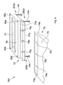
- Fig. 8 is a further inventive embodiment variant of a multi-part shower base plate 50c shown schematically and in perspective. It consists of a plate part, which comprises the drainage system and is thus referred to below as the drainage plate part 69 and a further plate part, which basically corresponds to the previously described embodiments of support plates or shower floor panels, can be placed and thus referred to as lay-on plate member 70 becomes.
- the drain plate portion 69 is preferably factory pre-assembled with a gutter 71 and mounting holes 62b-62e through which endless threaded rods 14d, 14e and 14f are operable in height adjustments 200c, 200d and 200e as disclosed heretofore.
- the drainage plate part 69 has a step-shaped, positively shaped connecting edge 72 with a bearing surface 74a, in which rivet nuts 75a-75c are inserted.
- the laying-on plate part 70 has a corresponding stepped, negative connecting edge 73 with a bearing surface 74b. After the two bearing surfaces 74a and 74b have been placed on top of each other, the laying plate part 70 can be screwed with countersunk screws through countersunk holes 76a-76c into the rivet nuts 75a-75c and thus firmly connected to the drain plate part 69.
- the rivet nuts 75a-75c in the bearing surface 74a of the drain plate member 69 are fixed as conventional nuts or threaded sleeves with a mounting plate 77a at the bottom of the drain plate member 69 connected, for example by being welded, provided that the mounting plate 77a preferably made of weldable metal consists.
- the mounting plate 77a preferably made of weldable metal consists.
Landscapes
- Health & Medical Sciences (AREA)
- Public Health (AREA)
- Epidemiology (AREA)
- General Health & Medical Sciences (AREA)
- Floor Finish (AREA)
- Legs For Furniture In General (AREA)
Applications Claiming Priority (1)
| Application Number | Priority Date | Filing Date | Title |
|---|---|---|---|
| AT2652009 | 2009-04-24 |
Publications (4)
| Publication Number | Publication Date |
|---|---|
| EP2245973A2 true EP2245973A2 (fr) | 2010-11-03 |
| EP2245973A3 EP2245973A3 (fr) | 2014-10-22 |
| EP2245973B1 EP2245973B1 (fr) | 2020-04-08 |
| EP2245973B8 EP2245973B8 (fr) | 2020-08-26 |
Family
ID=42355339
Family Applications (1)
| Application Number | Title | Priority Date | Filing Date |
|---|---|---|---|
| EP10004271.2A Active EP2245973B8 (fr) | 2009-04-24 | 2010-04-22 | Système de sous-construction pour bacs de douche et sols de douche |
Country Status (1)
| Country | Link |
|---|---|
| EP (1) | EP2245973B8 (fr) |
Cited By (8)
| Publication number | Priority date | Publication date | Assignee | Title |
|---|---|---|---|---|
| EP2700342A1 (fr) | 2012-08-19 | 2014-02-26 | Urs Gassmann | Plaque pour sol de douche |
| CH706848A1 (de) * | 2012-08-17 | 2014-02-28 | Urs Gassmann | Duschbodenplatte. |
| EP2572615A3 (fr) * | 2011-09-21 | 2014-08-06 | Sanipat GmbH | Tableau portatif pour baignoires et douches |
| EP3056618A1 (fr) * | 2015-02-10 | 2016-08-17 | SANIPAT GmbH | Socle de gouttiere reglable en hauteur pour recouvrir une gouttiere |
| EP2687136B1 (fr) * | 2012-07-20 | 2017-03-15 | Dallmer GmbH & Co. KG | Élément de douche |
| CN107916605A (zh) * | 2017-10-16 | 2018-04-17 | 广东省建筑科学研究院集团股份有限公司 | 一种用于改性树脂多功能路面超薄层施工的摊铺车 |
| CN111481087A (zh) * | 2019-01-25 | 2020-08-04 | 华中科技大学同济医学院附属协和医院 | 一种移动洗浴装置 |
| CN119184525A (zh) * | 2024-11-05 | 2024-12-27 | 华科住宅工业(东莞)有限公司 | 一种整体卫浴防漏水的拼装底盘 |
Family Cites Families (5)
| Publication number | Priority date | Publication date | Assignee | Title |
|---|---|---|---|---|
| DE9317159U1 (de) * | 1993-11-10 | 1994-02-10 | Beckmann, Hans-Jürgen, 23623 Ahrensbök | Universalgestell für Viertelkreis- und 5-Eck-Brausewannen |
| DE29602386U1 (de) * | 1996-02-12 | 1996-04-25 | Alpha - Sanitärvertriebs GmbH, 47805 Krefeld | Wannenträger, insbesondere Badewannen- und Duschwannenträger |
| ATE246469T1 (de) * | 1999-03-23 | 2003-08-15 | Illbruck Gmbh | Verfahren zur installation eines wannenträgers und in einem wannenträger aufgenommene wannenform |
| JP2002088839A (ja) * | 2000-09-21 | 2002-03-27 | Toto Ltd | 排水トラップを備えた浴室ユニット |
| AT8143U1 (de) * | 2004-12-10 | 2006-02-15 | Hl Hutterer & Lechner Gmbh | Befestigungselement für einen sanitärbauteil |
-
2010
- 2010-04-22 EP EP10004271.2A patent/EP2245973B8/fr active Active
Non-Patent Citations (1)
| Title |
|---|
| None |
Cited By (8)
| Publication number | Priority date | Publication date | Assignee | Title |
|---|---|---|---|---|
| EP2572615A3 (fr) * | 2011-09-21 | 2014-08-06 | Sanipat GmbH | Tableau portatif pour baignoires et douches |
| EP2687136B1 (fr) * | 2012-07-20 | 2017-03-15 | Dallmer GmbH & Co. KG | Élément de douche |
| CH706848A1 (de) * | 2012-08-17 | 2014-02-28 | Urs Gassmann | Duschbodenplatte. |
| EP2700342A1 (fr) | 2012-08-19 | 2014-02-26 | Urs Gassmann | Plaque pour sol de douche |
| EP3056618A1 (fr) * | 2015-02-10 | 2016-08-17 | SANIPAT GmbH | Socle de gouttiere reglable en hauteur pour recouvrir une gouttiere |
| CN107916605A (zh) * | 2017-10-16 | 2018-04-17 | 广东省建筑科学研究院集团股份有限公司 | 一种用于改性树脂多功能路面超薄层施工的摊铺车 |
| CN111481087A (zh) * | 2019-01-25 | 2020-08-04 | 华中科技大学同济医学院附属协和医院 | 一种移动洗浴装置 |
| CN119184525A (zh) * | 2024-11-05 | 2024-12-27 | 华科住宅工业(东莞)有限公司 | 一种整体卫浴防漏水的拼装底盘 |
Also Published As
| Publication number | Publication date |
|---|---|
| EP2245973A3 (fr) | 2014-10-22 |
| EP2245973B1 (fr) | 2020-04-08 |
| EP2245973B8 (fr) | 2020-08-26 |
Similar Documents
| Publication | Publication Date | Title |
|---|---|---|
| EP2245973B1 (fr) | Système de sous-construction pour bacs de douche et sols de douche | |
| EP3031990B1 (fr) | Siphon de sol | |
| EP2354341B1 (fr) | Goulotte dotée d'un recouvrement réglable en hauteur | |
| DE102006007471A1 (de) | Duschbodenelement und Trägerelement dafür, sowie Duschbodenunterbau aus einem Duschbodenelement und einem Trägerelement für bodengleiche Duschen | |
| EP2756137B1 (fr) | Caniveau d'évacuation pour une douche ras du sol | |
| EP2067902B1 (fr) | Procédé d'intégration d'une évacuation dans un sous-sol, évacuation dotée d'un bac d'évacuation ainsi que sols de bâtiments dotés d'une telle évacuation | |
| DE3320617A1 (de) | Vorgefertigte verkleidungsschuerze fuer badewannen | |
| DE202008005293U1 (de) | Duschbodenuntergestell | |
| AT508227B1 (de) | Unterbausystem für duschwannen und duschböden | |
| DE19525082C2 (de) | Wandelement für Hochbauten und Verfahren zu seiner Herstellung | |
| DE102006026707A1 (de) | Duschwanne | |
| EP1162907A1 (fr) | Procede pour l'installation d'un support de cuve et coque de cuve montee dans un tel support | |
| DE10007101A1 (de) | Nivelliervorrichtung für gerade Flächen | |
| EP2929818B1 (fr) | Bac à douche | |
| DE4124460A1 (de) | Installationsblock | |
| DE102018008598A1 (de) | Abstandshalter und Befestiger für durch eine Fassade hindurch am Gebäude zu befestigenden Teile | |
| DE29507126U1 (de) | Nachträglich anbaubarer Balkon oder Wintergarten | |
| WO2010075855A1 (fr) | Système de goujon pour construction en béton | |
| EP0723757A1 (fr) | Système de support pour baignoires ou bacs à douche | |
| EP2177689B1 (fr) | Cadre doté d'un couvercle | |
| DE19942050A1 (de) | Bodenschiene | |
| EP3339522B1 (fr) | Système ou kit de fixation de caniveaux de douche | |
| EP2700342B1 (fr) | Plaque pour sol de douche | |
| DE202006019811U1 (de) | Trägerelement für ein Duschbodenelement für bodengleiche Duschen | |
| EP0116012B1 (fr) | Socle-élément préfabriqué pour baignoires et cuvettes de douches |
Legal Events
| Date | Code | Title | Description |
|---|---|---|---|
| PUAI | Public reference made under article 153(3) epc to a published international application that has entered the european phase |
Free format text: ORIGINAL CODE: 0009012 |
|
| AK | Designated contracting states |
Kind code of ref document: A2 Designated state(s): AT BE BG CH CY CZ DE DK EE ES FI FR GB GR HR HU IE IS IT LI LT LU LV MC MK MT NL NO PL PT RO SE SI SK SM TR |
|
| AX | Request for extension of the european patent |
Extension state: AL BA ME RS |
|
| PUAL | Search report despatched |
Free format text: ORIGINAL CODE: 0009013 |
|
| AK | Designated contracting states |
Kind code of ref document: A3 Designated state(s): AT BE BG CH CY CZ DE DK EE ES FI FR GB GR HR HU IE IS IT LI LT LU LV MC MK MT NL NO PL PT RO SE SI SK SM TR |
|
| AX | Request for extension of the european patent |
Extension state: AL BA ME RS |
|
| RIC1 | Information provided on ipc code assigned before grant |
Ipc: A47K 3/16 20060101AFI20140917BHEP Ipc: A47K 3/17 20060101ALI20140917BHEP Ipc: A47K 3/40 20060101ALI20140917BHEP |
|
| 17P | Request for examination filed |
Effective date: 20150420 |
|
| RBV | Designated contracting states (corrected) |
Designated state(s): AT BE BG CH CY CZ DE DK EE ES FI FR GB GR HR HU IE IS IT LI LT LU LV MC MK MT NL NO PL PT RO SE SI SK SM TR |
|
| STAA | Information on the status of an ep patent application or granted ep patent |
Free format text: STATUS: EXAMINATION IS IN PROGRESS |
|
| 17Q | First examination report despatched |
Effective date: 20180925 |
|
| RAP1 | Party data changed (applicant data changed or rights of an application transferred) |
Owner name: SANIPAT GMBH |
|
| RIN1 | Information on inventor provided before grant (corrected) |
Inventor name: SANIPAT GMBH |
|
| GRAP | Despatch of communication of intention to grant a patent |
Free format text: ORIGINAL CODE: EPIDOSNIGR1 |
|
| STAA | Information on the status of an ep patent application or granted ep patent |
Free format text: STATUS: GRANT OF PATENT IS INTENDED |
|
| INTG | Intention to grant announced |
Effective date: 20191022 |
|
| GRAS | Grant fee paid |
Free format text: ORIGINAL CODE: EPIDOSNIGR3 |
|
| GRAA | (expected) grant |
Free format text: ORIGINAL CODE: 0009210 |
|
| STAA | Information on the status of an ep patent application or granted ep patent |
Free format text: STATUS: THE PATENT HAS BEEN GRANTED |
|
| AK | Designated contracting states |
Kind code of ref document: B1 Designated state(s): AT BE BG CH CY CZ DE DK EE ES FI FR GB GR HR HU IE IS IT LI LT LU LV MC MK MT NL NO PL PT RO SE SI SK SM TR |
|
| REG | Reference to a national code |
Ref country code: GB Ref legal event code: FG4D Free format text: NOT ENGLISH |
|
| RIN1 | Information on inventor provided before grant (corrected) |
Inventor name: GRASSMANN, URS |
|
| REG | Reference to a national code |
Ref country code: CH Ref legal event code: EP Ref country code: AT Ref legal event code: REF Ref document number: 1253203 Country of ref document: AT Kind code of ref document: T Effective date: 20200415 |
|
| REG | Reference to a national code |
Ref country code: DE Ref legal event code: R096 Ref document number: 502010016563 Country of ref document: DE |
|
| REG | Reference to a national code |
Ref country code: IE Ref legal event code: FG4D Free format text: LANGUAGE OF EP DOCUMENT: GERMAN |
|
| GRAT | Correction requested after decision to grant or after decision to maintain patent in amended form |
Free format text: ORIGINAL CODE: EPIDOSNCDEC |
|
| REG | Reference to a national code |
Ref country code: CH Ref legal event code: NV Representative=s name: PATENT- AND MARKENBUERO REB GMBH, CH Ref country code: CH Ref legal event code: PK Free format text: BERICHTIGUNG ERFINDER |
|
| REG | Reference to a national code |
Ref country code: CH Ref legal event code: PK Free format text: BERICHTIGUNG B8 Ref country code: CH Ref legal event code: PK Free format text: BERICHTIGUNGEN |
|
| RIN2 | Information on inventor provided after grant (corrected) |
Inventor name: GASSMANN, URS |
|
| REG | Reference to a national code |
Ref country code: NL Ref legal event code: MP Effective date: 20200408 |
|
| REG | Reference to a national code |
Ref country code: LT Ref legal event code: MG4D |
|
| PG25 | Lapsed in a contracting state [announced via postgrant information from national office to epo] |
Ref country code: FI Free format text: LAPSE BECAUSE OF FAILURE TO SUBMIT A TRANSLATION OF THE DESCRIPTION OR TO PAY THE FEE WITHIN THE PRESCRIBED TIME-LIMIT Effective date: 20200408 Ref country code: GR Free format text: LAPSE BECAUSE OF FAILURE TO SUBMIT A TRANSLATION OF THE DESCRIPTION OR TO PAY THE FEE WITHIN THE PRESCRIBED TIME-LIMIT Effective date: 20200709 Ref country code: LT Free format text: LAPSE BECAUSE OF FAILURE TO SUBMIT A TRANSLATION OF THE DESCRIPTION OR TO PAY THE FEE WITHIN THE PRESCRIBED TIME-LIMIT Effective date: 20200408 Ref country code: PT Free format text: LAPSE BECAUSE OF FAILURE TO SUBMIT A TRANSLATION OF THE DESCRIPTION OR TO PAY THE FEE WITHIN THE PRESCRIBED TIME-LIMIT Effective date: 20200817 Ref country code: IS Free format text: LAPSE BECAUSE OF FAILURE TO SUBMIT A TRANSLATION OF THE DESCRIPTION OR TO PAY THE FEE WITHIN THE PRESCRIBED TIME-LIMIT Effective date: 20200808 Ref country code: NO Free format text: LAPSE BECAUSE OF FAILURE TO SUBMIT A TRANSLATION OF THE DESCRIPTION OR TO PAY THE FEE WITHIN THE PRESCRIBED TIME-LIMIT Effective date: 20200708 Ref country code: SE Free format text: LAPSE BECAUSE OF FAILURE TO SUBMIT A TRANSLATION OF THE DESCRIPTION OR TO PAY THE FEE WITHIN THE PRESCRIBED TIME-LIMIT Effective date: 20200408 Ref country code: NL Free format text: LAPSE BECAUSE OF FAILURE TO SUBMIT A TRANSLATION OF THE DESCRIPTION OR TO PAY THE FEE WITHIN THE PRESCRIBED TIME-LIMIT Effective date: 20200408 |
|
| PG25 | Lapsed in a contracting state [announced via postgrant information from national office to epo] |
Ref country code: HR Free format text: LAPSE BECAUSE OF FAILURE TO SUBMIT A TRANSLATION OF THE DESCRIPTION OR TO PAY THE FEE WITHIN THE PRESCRIBED TIME-LIMIT Effective date: 20200408 Ref country code: BG Free format text: LAPSE BECAUSE OF FAILURE TO SUBMIT A TRANSLATION OF THE DESCRIPTION OR TO PAY THE FEE WITHIN THE PRESCRIBED TIME-LIMIT Effective date: 20200708 Ref country code: LV Free format text: LAPSE BECAUSE OF FAILURE TO SUBMIT A TRANSLATION OF THE DESCRIPTION OR TO PAY THE FEE WITHIN THE PRESCRIBED TIME-LIMIT Effective date: 20200408 |
|
| REG | Reference to a national code |
Ref country code: DE Ref legal event code: R097 Ref document number: 502010016563 Country of ref document: DE |
|
| PG25 | Lapsed in a contracting state [announced via postgrant information from national office to epo] |
Ref country code: ES Free format text: LAPSE BECAUSE OF FAILURE TO SUBMIT A TRANSLATION OF THE DESCRIPTION OR TO PAY THE FEE WITHIN THE PRESCRIBED TIME-LIMIT Effective date: 20200408 Ref country code: MC Free format text: LAPSE BECAUSE OF FAILURE TO SUBMIT A TRANSLATION OF THE DESCRIPTION OR TO PAY THE FEE WITHIN THE PRESCRIBED TIME-LIMIT Effective date: 20200408 Ref country code: DK Free format text: LAPSE BECAUSE OF FAILURE TO SUBMIT A TRANSLATION OF THE DESCRIPTION OR TO PAY THE FEE WITHIN THE PRESCRIBED TIME-LIMIT Effective date: 20200408 Ref country code: EE Free format text: LAPSE BECAUSE OF FAILURE TO SUBMIT A TRANSLATION OF THE DESCRIPTION OR TO PAY THE FEE WITHIN THE PRESCRIBED TIME-LIMIT Effective date: 20200408 Ref country code: SM Free format text: LAPSE BECAUSE OF FAILURE TO SUBMIT A TRANSLATION OF THE DESCRIPTION OR TO PAY THE FEE WITHIN THE PRESCRIBED TIME-LIMIT Effective date: 20200408 Ref country code: IT Free format text: LAPSE BECAUSE OF FAILURE TO SUBMIT A TRANSLATION OF THE DESCRIPTION OR TO PAY THE FEE WITHIN THE PRESCRIBED TIME-LIMIT Effective date: 20200408 Ref country code: RO Free format text: LAPSE BECAUSE OF FAILURE TO SUBMIT A TRANSLATION OF THE DESCRIPTION OR TO PAY THE FEE WITHIN THE PRESCRIBED TIME-LIMIT Effective date: 20200408 Ref country code: CZ Free format text: LAPSE BECAUSE OF FAILURE TO SUBMIT A TRANSLATION OF THE DESCRIPTION OR TO PAY THE FEE WITHIN THE PRESCRIBED TIME-LIMIT Effective date: 20200408 Ref country code: LU Free format text: LAPSE BECAUSE OF NON-PAYMENT OF DUE FEES Effective date: 20200422 |
|
| REG | Reference to a national code |
Ref country code: BE Ref legal event code: MM Effective date: 20200430 |
|
| PLBE | No opposition filed within time limit |
Free format text: ORIGINAL CODE: 0009261 |
|
| STAA | Information on the status of an ep patent application or granted ep patent |
Free format text: STATUS: NO OPPOSITION FILED WITHIN TIME LIMIT |
|
| PG25 | Lapsed in a contracting state [announced via postgrant information from national office to epo] |
Ref country code: PL Free format text: LAPSE BECAUSE OF FAILURE TO SUBMIT A TRANSLATION OF THE DESCRIPTION OR TO PAY THE FEE WITHIN THE PRESCRIBED TIME-LIMIT Effective date: 20200408 Ref country code: SK Free format text: LAPSE BECAUSE OF FAILURE TO SUBMIT A TRANSLATION OF THE DESCRIPTION OR TO PAY THE FEE WITHIN THE PRESCRIBED TIME-LIMIT Effective date: 20200408 Ref country code: BE Free format text: LAPSE BECAUSE OF NON-PAYMENT OF DUE FEES Effective date: 20200430 |
|
| 26N | No opposition filed |
Effective date: 20210112 |
|
| GBPC | Gb: european patent ceased through non-payment of renewal fee |
Effective date: 20200708 |
|
| PG25 | Lapsed in a contracting state [announced via postgrant information from national office to epo] |
Ref country code: IE Free format text: LAPSE BECAUSE OF NON-PAYMENT OF DUE FEES Effective date: 20200422 Ref country code: FR Free format text: LAPSE BECAUSE OF NON-PAYMENT OF DUE FEES Effective date: 20200608 Ref country code: GB Free format text: LAPSE BECAUSE OF NON-PAYMENT OF DUE FEES Effective date: 20200708 |
|
| PG25 | Lapsed in a contracting state [announced via postgrant information from national office to epo] |
Ref country code: SI Free format text: LAPSE BECAUSE OF FAILURE TO SUBMIT A TRANSLATION OF THE DESCRIPTION OR TO PAY THE FEE WITHIN THE PRESCRIBED TIME-LIMIT Effective date: 20200408 |
|
| PG25 | Lapsed in a contracting state [announced via postgrant information from national office to epo] |
Ref country code: TR Free format text: LAPSE BECAUSE OF FAILURE TO SUBMIT A TRANSLATION OF THE DESCRIPTION OR TO PAY THE FEE WITHIN THE PRESCRIBED TIME-LIMIT Effective date: 20200408 Ref country code: MT Free format text: LAPSE BECAUSE OF FAILURE TO SUBMIT A TRANSLATION OF THE DESCRIPTION OR TO PAY THE FEE WITHIN THE PRESCRIBED TIME-LIMIT Effective date: 20200408 Ref country code: CY Free format text: LAPSE BECAUSE OF FAILURE TO SUBMIT A TRANSLATION OF THE DESCRIPTION OR TO PAY THE FEE WITHIN THE PRESCRIBED TIME-LIMIT Effective date: 20200408 |
|
| PG25 | Lapsed in a contracting state [announced via postgrant information from national office to epo] |
Ref country code: MK Free format text: LAPSE BECAUSE OF FAILURE TO SUBMIT A TRANSLATION OF THE DESCRIPTION OR TO PAY THE FEE WITHIN THE PRESCRIBED TIME-LIMIT Effective date: 20200408 |
|
| PGFP | Annual fee paid to national office [announced via postgrant information from national office to epo] |
Ref country code: DE Payment date: 20230418 Year of fee payment: 14 Ref country code: CH Payment date: 20230502 Year of fee payment: 14 |
|
| PGFP | Annual fee paid to national office [announced via postgrant information from national office to epo] |
Ref country code: AT Payment date: 20230414 Year of fee payment: 14 |
|
| REG | Reference to a national code |
Ref country code: DE Ref legal event code: R119 Ref document number: 502010016563 Country of ref document: DE |
|
| REG | Reference to a national code |
Ref country code: CH Ref legal event code: PL |
|
| REG | Reference to a national code |
Ref country code: AT Ref legal event code: MM01 Ref document number: 1253203 Country of ref document: AT Kind code of ref document: T Effective date: 20240422 |
|
| PG25 | Lapsed in a contracting state [announced via postgrant information from national office to epo] |
Ref country code: DE Free format text: LAPSE BECAUSE OF NON-PAYMENT OF DUE FEES Effective date: 20241105 |
|
| PG25 | Lapsed in a contracting state [announced via postgrant information from national office to epo] |
Ref country code: AT Free format text: LAPSE BECAUSE OF NON-PAYMENT OF DUE FEES Effective date: 20240422 |
|
| PG25 | Lapsed in a contracting state [announced via postgrant information from national office to epo] |
Ref country code: DE Free format text: LAPSE BECAUSE OF NON-PAYMENT OF DUE FEES Effective date: 20241105 Ref country code: AT Free format text: LAPSE BECAUSE OF NON-PAYMENT OF DUE FEES Effective date: 20240422 Ref country code: CH Free format text: LAPSE BECAUSE OF NON-PAYMENT OF DUE FEES Effective date: 20240430 |