EP2700342A1 - Plaque pour sol de douche - Google Patents
Plaque pour sol de douche Download PDFInfo
- Publication number
- EP2700342A1 EP2700342A1 EP12005944.9A EP12005944A EP2700342A1 EP 2700342 A1 EP2700342 A1 EP 2700342A1 EP 12005944 A EP12005944 A EP 12005944A EP 2700342 A1 EP2700342 A1 EP 2700342A1
- Authority
- EP
- European Patent Office
- Prior art keywords
- shower
- bottom plate
- floor panel
- adjustable
- plate
- Prior art date
- Legal status (The legal status is an assumption and is not a legal conclusion. Google has not performed a legal analysis and makes no representation as to the accuracy of the status listed.)
- Granted
Links
Images


Classifications
-
- A—HUMAN NECESSITIES
- A47—FURNITURE; DOMESTIC ARTICLES OR APPLIANCES; COFFEE MILLS; SPICE MILLS; SUCTION CLEANERS IN GENERAL
- A47K—SANITARY EQUIPMENT; ACCESSORIES THEREFOR, e.g. TOILET ACCESSORIES
- A47K3/00—Baths; Showers; Appurtenances therefor
- A47K3/28—Showers or bathing douches
- A47K3/40—Pans or trays
- A47K3/405—Pans or trays flush with the surrounding floor, e.g. for easy access
-
- A—HUMAN NECESSITIES
- A47—FURNITURE; DOMESTIC ARTICLES OR APPLIANCES; COFFEE MILLS; SPICE MILLS; SUCTION CLEANERS IN GENERAL
- A47K—SANITARY EQUIPMENT; ACCESSORIES THEREFOR, e.g. TOILET ACCESSORIES
- A47K3/00—Baths; Showers; Appurtenances therefor
- A47K3/008—Sealing between wall and bathtub or shower tray
-
- A—HUMAN NECESSITIES
- A47—FURNITURE; DOMESTIC ARTICLES OR APPLIANCES; COFFEE MILLS; SPICE MILLS; SUCTION CLEANERS IN GENERAL
- A47K—SANITARY EQUIPMENT; ACCESSORIES THEREFOR, e.g. TOILET ACCESSORIES
- A47K3/00—Baths; Showers; Appurtenances therefor
- A47K3/16—Devices for fastening baths to floors or walls; Adjustable bath feet ; Lining panels or attachments therefor
- A47K3/17—Adjustable bath feet
-
- E—FIXED CONSTRUCTIONS
- E03—WATER SUPPLY; SEWERAGE
- E03F—SEWERS; CESSPOOLS
- E03F5/00—Sewerage structures
- E03F5/04—Gullies inlets, road sinks, floor drains with or without odour seals or sediment traps
- E03F5/0407—Floor drains for indoor use
- E03F5/0408—Floor drains for indoor use specially adapted for showers
Definitions
- the present invention relates to a shower floor panel, as used in creating a modern shower cubicle without a shower tray.
- Such a floor construction may be a screed, a concrete floor, a raw concrete floor, an overburden, a floating screed, a finished floor, a Giessmörtelbett or a base floor and is generally referred to below only floor.
- the shower floor panels can, as already by the same applicant in the European patent application EP 2 245 973 A2 be equipped with height-adjustable feet and with appropriate openings for a drain, be it in the form of a drain or a drainage channel.
- the requirements for a high quality shower floor panel are manifold. So it is necessary, for example, that not only an exact height adjustment or gradient adjustment, but also a stable seat of the shower base plate is guaranteed.
- the shower floor plate must be stable enough in itself, but also stable, otherwise a permanent and tight tiling can be achieved only bad. Furthermore, the requirements for tightness, sound insulation, but also practicality and cost efficiency high.
- the shower base plate has no integrated device to be fixed in all four directions of extension on all four sides (if it is a square shower floor panel) against the connection walls.
- the shower base plate indeed has height-adjustable feet, but the shower base plate has no corresponding openings in order to guarantee the operability of these height-adjustable feet even in the installed state.
- Another disadvantage may be that the drainage device must be used or fitted by the fitter on site. This can adversely affect the stable fit of the shower floor panel or the tightness of the drain or later applied tiling. It may also be disadvantageous if the installer must install sealing or soundproofing profiles on site.
- Another disadvantage may be that the surface of the shower base plate is flat and thus a slightly raised heel is formed when attaching sealing profiles. If tiles are subsequently laid over this section, this can result in a heel in the tile floor or hollow areas under the tiles, which in turn make it easier to break the tiles or generate sound.
- the object of the present invention is to provide a shower floor plate that meets the above requirements and eliminates the mentioned disadvantages as far as possible.
- a first part is preferably designed as a so-called shower channel part into which an outflow or even a shower channel can already be integrated at the factory, but in any case has features for connection to such.
- At least a second part is configured as a shower floor panel main part.
- the shower channel part can preferably always be the same width at the factory and only its length ex works is variable. Its width is preferably constant at the factory, virtually standardized.
- the shower floor panel main part can be manufactured variably both in length, as well as in its width ex factory.
- the shower channel part and the shower base plate main part are preferably connectable to one another by means of a metal profile and screw connections. But there are also other compounds conceivable, each with or without metal profile and in each case with or without screws or taps, for example by means of overlapping and underlapping edges or a positive spring-and-groove construction.
- the connection between the shower channel part and the shower floor panel main part, whether in the form of a metal profile or in the form of a positive-locking construction, is referred to below as the general connection piece.
- a further preferred embodiment variant of a shower floor panel according to the invention has a flattening on the upper side. That is, a smaller thickness of the shower base plate is provided for the width of that part with which a sealing profile between the connection wall or floor and shower base plate overlaps the shower base plate.
- the difference of the full thickness of the shower bottom plate to the lower makes about the strength of Sealing profiles in glued or otherwise fastened state.
- the sealing profile can therefore be flush and without being applied glued or otherwise secured in the edge flattening. This results in a completely flat top of the shower base plate, which is optimally tiled, without the risk of tile breakage or a sound generated by hollow spots under the tiles.
- thicker and more resistant sealing profiles can be used.
- a further embodiment variant of a shower floor panel according to the invention has a shower channel which is preferably glued and / or screwed and / or welded into the shower channel part and which is already integrated at the factory.
- This shower channel may have different shapes and one or more drainage holes or nozzles.
- the connecting piece between the shower channel part and the shower floor panel main part is preferably designed variably according to a further embodiment variant of a shower floor panel according to the invention.
- This can be done on the one hand by different widths metal profiles can be attached, but still provide the necessary stability of the entire shower base plate.
- slots can also be arranged in the metal profiles, the shower base plate or the positive-locking parts, preferably with position locks, so that the shower base plate can still be adjusted in size on site when installed, if the prefabricated made-to-measure shower base plate should not fit exactly ,
- the manufacturer gains in this way, a cost savings, because he no longer has to produce individual exact custom-made, but only manufacturing for specific areas.
- the material of which the shower bottom plate or the two plate parts mainly consist is preferably MDF, HDF or HB board, furthermore preferably glued moisture-resistant. Basically comes as a material but also plastic, metal or carbon into consideration, fully made of the respective material or laminated or built in layers or combining the materials mentioned.
- An inventive shower bottom plate preferably has at least one mounting plate on its underside, which advantageously distributes the pressure of a foot to a larger area. Further preferably, the mounting plate is recessed in the material of the shower base plate in a recess. The fact that the mounting plate can be mounted flush against the inner edge of the recess results in improved lateral stability of the mounting plates. Their recessed mounting within a recess also provides an improved packaging and stackability of the shower floor panels.
- the mounting plates preferably have identically predrilled, several smaller mounting holes for attaching the mounting plate itself to the shower base plate.
- a fastening plate according to the invention has at least one slightly larger bore, which is formed into a threaded sleeve or into which a threaded sleeve can be inserted as desired. This threaded sleeve is intended for the screwing of set screws that fix adjustable side stabilizers or adjustable shuttering aids or extensions of the shower surface or other structural parts.
- Side stabilizers are in a simplest form angles that provide bracing to a terminal wall or floor
- shuttering aids are panels fixed to the shower floor panel in a simplest form that extend the shower floor panel approximately at right angles so that, for example, a base floor can be poured Built wall can be.
- adjustable side stabilizers or adjustable shuttering aids preferably have a slidable in a slot in the interior of the shower base plate slat, which is fixable by means of the adjusting screw in the desired position.
- These slats can optionally also be spring-resistant, which means that in the case of a shower floor panel with such spring-reinforced slats, the slats are preferably pushed in to the maximum before setting and are fixed with the set screw in this maximum retracted position. Then the shower base plate is placed in the shower cubicle or on the connection walls and by loosening the screws, the spring force presses the adjustable side stabilizers or adjustable Abschalungs Huawein automatically to the connection walls.
- the inventive mounting plates also preferably have at least one, even slightly larger bore, which is flanked diametrically by two threaded holes.
- This configuration of holes is arranged to receive a height-adjustable threaded stem, which in turn is preferably in two versions, namely a first comprising a threaded rod, a socket and a locknut.
- the threaded rod preferably has an inner or outer hexagon at one end and is screwed into the base with the opposite end and fixed with the lock nut.
- the base in turn preferably has on its underside a sound-absorbing and / or friction-increasing material.
- This first thread root design can be used in a threaded sleeve of a retaining plate, which in turn is screwed to the bore configuration of the mounting plate, preferably with discs of sound-absorbing material.
- a second thread-foot design complements the threaded rod-base combination to a preferably U-shaped holder, in which by means of two nuts, a threaded bolt can be used.
- This threaded bolt has not only an external but also an internal thread into which in turn the threaded rod of the threaded rod-socket combination can be screwed.
- the preferably U-shaped holder may also have a C-shape in the form of a bracket, or else be cup-shaped. Essential is its holding property for an inserted nut or an integrated thread in which the threaded bolt is held.
- the preferably U-shaped holder is hereinafter referred to as a holder.
- the bearing surfaces on the holder for the two nuts, which hold the threaded bolt, are preferably rubberized or clad with a sound-absorbing material.
- the first thread-root design is designed for lower heights, while the second thread-root design provides a stable hold even at higher heights and more adjustment possibilities.
- the largest of the holes in the mounting plate that is, the one that is diametrically flanked by two threaded holes is preferably continued with a concentric bore through the entire shower base plate, so that the threaded rod of the first and second threaded feet execution by means of the inner or outer hexagon and but also the threaded bolt remain operable by means of a slot from above, so even if the shower base plate is already laid.
- An analog operability from above is also realized for the medium-sized mounting holes by the screw, which is bolted by a threaded sleeve disposed therein, at the end, which is opposite to the screw head, also has an internal or external hexagon.
- the medium-sized bore or the threaded sleeve is continued by a through the shower floor plate through hole and thus can be operated from above even with already installed shower base plate, the screws for the side stabilizers or shuttering aids.
- these holes can be closed with caps.
- a shower base plate according to the invention can also be mounted on support frames, as by the same applicant, for example in the European patent application EP 2 245 973 A2 described.
- a shower bottom plate according to the invention tapers in cross-section towards that edge on which the shower channel is arranged in parallel, for example with a total width of 1.0 m, a thickness of 50 mm and a gradient of 1%, by 0.5 mm.
- a shower base plate according to the invention is supplied with a shower channel cover, which in turn compensates for the respective gradient of the shower base plate - in accordance with the requirement for grading and according to the dimensions.
- the installer merely has to align the side edge of that edge, which is opposite the shower channel, and level the top of the shower channel cover, and then remove the shower channel cover.
- An inventive shower floor panel can be combined with gutters that can be walled into a connection wall.
- the shower floor plate can connect to this gutter in the assembled state and is well suited because of the flattening on the edge.
- a preferably flexible sealing profile can already be arranged at the factory on a shower floor panel according to the invention.
- This sealing profile is folded inwards when setting the shower base plate and after the height adjustment and lateral fixation of the shower base plate to the connecting walls created and sealingly attached, for example glued or slurried.
- the sealing profile in the assembled state preferably has a cut protection, as described by the same applicant for the first time in the Austrian patent application AT 510 127 A1 was disclosed, converted from the Austrian utility model AT GM 438/2010 of 09.07.2010 ,
- the top of a shower floor panel according to the invention is preferably coated with a cement-liquid-gum-coating, for sealing, but also for improving the adhesion of the tile adhesive.
- the connector in particular, unless it is made of a stainless metal or steel, is preferably treated against rust.
- a sealing mat can also be placed, which preferably projects laterally beyond the shower floor panel. This excess mass can then replace a sealing profile and, for example, also glued or slurried on the connection walls or the floor.
- either the first or the second method is applicable, but not both at the same time, depending on whether an interchangeable or a length-adjustable connecting piece is provided in the sense of a variable shower base plate.
- the disclosed different design variants of a shower floor panel according to the invention can be combined with one another.
- the different design variants of connecting pieces can also be implemented displaceably or combined with that design variant of a shower base plate which has a flattening for the sealing profile or those design variants which have only one or more fastening plates on the underside or with that design variant which has a displaceable one Side stabilizer or a spring-reinforced has.
- All design variants may include the first or the second thread root design or both, and all design variants may produce the slope by a in cross-section plane-parallel shower bottom plate is made by means of the roots in an inclined plane or the shower base plate in cross section is wedge-shaped.
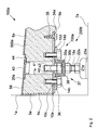
- a first embodiment variant of an inventive shower tray plate 100 is shown schematically in the assembled, but not finally mounted state. It is only indicated that the shower floor panel 100 is adjacent to a connection wall 1 and is on a floor 2, with a threaded foot 200 a.
- the shower floor panel 100 includes a shower tray main body 500 and a shower tray portion 600 having an integrated shower tray 400, the shower tray main body 500 and the shower tray portion 600 being connected by a connector 300.
- the shower bottom plate main part 500 preferably has a factory-variable width B DBP-HT and the shower channel part preferably has a factory-constant width B DR-T .
- the shower floor panel 100 has from a top edge 3 of an end face 4, on which a soundproofing profile 5 is arranged, toward a top edge 6 of an opposite end face 7, a slope G on.
- an upper side 8 of the shower base plate 100 is in an inclined plane and not a bottom 9, which in turn may be aligned horizontally. The latter benefits the stability of the thread root 200a, because it is exposed to less leverage.
- a mounting plate 10 is arranged, preferably countersunk in a recess 34.
- This mounting plate 10 has not shown first holes, fix them by the wood screws on the shower base plate main body 500.
- a threaded sleeve 12 of a retaining plate 13 is received in a second bore 11 in the mounting plate 10.
- the holding plate 13 is provided with screws 14a and 14b in FIG Tapped holes 15a and 15b of the mounting plate 10 as shown screwed or glued or both.
- the screw heads of the screws 14a and 14b are lined with annular discs of damping material 16a and 16b and the retaining plate 13 with a washer 17 of the same material.
- a threaded rod 18 is screwed, which has a hexagon socket 19 at its upper end, so that it remains operable through an operating opening 20 even when the shower base plate 100 is laid.
- the threaded rod 18 is screwed into a base 21 and fixed with a lock nut 22.
- the base 22 has on its underside a damping and friction-increasing layer 23.
- the connector 300 includes a tapered portion 24 a on the shower floor panel main body 500, and a tapered portion 24 b on the shower tray portion 600, each of which is grasped by an upper metal profile 25 and a lower metal profile 26. This is done by countersunk screws 27a and 27b are guided by a respective countersunk hole 28a and 28b in the upper metal section 25 and a respective threaded sleeve 29a and 29b in the lower metal section 26. Of course, it may be sufficient if the lower metal profile 26 has no threaded sleeves 29a and 29b, but only threaded holes. Instead of an upper flat metal profile 25 and a lower flat metal profile 26 also two T-profiles or even a one-piece I-profile come into consideration.
- the shower channel 400 is glued with flanks 30a and 30b in corresponding recesses 31a and 31b of the shower channel part 600 and forms a collecting trough 32 with a gradient and a discharge nozzle 33rd
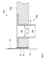
- a shower floor plate main part 500a of a shower floor plate 100a is shown schematically and shows a threaded root 200b, which is more stable than the threaded foot 200a of the Fig. 1 is and has a further adjustment range.
- a fixing plate 10a is fixed with wood screws 35.
- a preferably U-shaped holder 36 is attached, optionally additionally glued.
- the holder 36 has a bulge 37, which is lined inside and outside with damping material 38.
- a threaded bolt 40 in the bulge 37, which not only external thread, but also has a continuous inner longitudinal bore 41 with thread.
- a threaded rod 18a is screwed, with a base 21a, a lock nut 22a and a damping and friction-increasing layer 23a, analogous to the thread root 200a from the Fig. 1 ,
- the above-described parts constitute the thread root 200b standing on a bottom 2a.
- the threaded bolt 40 can also protrude through a hole 11a in the fastening plate 10a and has a slot 42 at an upper end so that it can be turned with a screwdriver from above through an operating opening 20a if required.
- the operating opening 20a is closed by a closure cap 43.
- An upper side 8a of the shower base plate main part 500a has, towards the edge, an edge flattening 44 into which a sealing profile can be glued without being applied.
- a soundproofing profile 5a is disposed toward a connection wall 1a.
- the top side 8a of the shower floor panel 100a is preferably coated with a cement-liquid rubber paint 58.
- the Fig. 3 schematically shows a shower bottom plate main part 500b of a shower floor plate 100b, with a side stabilizer 45.
- An adjusting screw 46 is seated in a threaded sleeve 12a, which in turn is inserted in a bore 56 of a mounting plate 10b.
- the attachment plate 10b is fixed to a lower surface 9b of the shower tray main body 500b in a recess 34b with wood screws 35a.
- an operation opening 20b is disposed so that the adjusting screw 46 can be operated.
- a fin 48 can be slid with a slot 49 when a toothed pulley 50 is loosened.
- the blade 48 is pressed against a bottom 57 of the cutout 47.
- the side stabilizer 45 further includes a support surface 51 on which a soundproofing profile 5b is disposed, toward a connection wall 1b.
- FIG. 4 1 schematically shows a shower floor panel main part 500c of a shower floor panel 100c, with an optional design variant of a side stabilizer 45a. It is again provided on a bottom 9c of the shower bottom plate main body 500c a recess 34c in which a fixing plate 10c is fixed by means of wood screws 35b.
- a set screw 46a is seated in a threaded sleeve 12b inserted in a bore 56a of the mounting plate 10c and allows a louver 48a of the side stabilizer 45a to move approximately horizontally in a cutout 47a in the shower tray main body 500c thanks to an elongated hole 49a provided the set screw 46a is not tightened so tightly that the lamella 48a is fixed by means of a disc 52 on an underside 57a of the cutout 47a.
- the set screw 46a is released through an operation opening 20c in an upper surface 8c of the shower floor panel main body 500c, the spring force of a spring 53 presses a support surface 51a and a soundproofing profile 5c disposed thereon against a connection wall 1c.
- adjustable fixings for side stabilizers 45, 45a come out according to a simplest embodiment variant without sprocket and / or spring.
- the cutout 47 does not have to be arranged approximately in the middle of the thickness of the shower bottom plate, but may also be provided on the underside 9b or 9c.
- the Fig. 5 schematically shows a shower channel part 600a of a shower floor plate 100d, in which a shower channel 400a is integrated.
- the shower channel 400a is shown cut so that one sees a drip pan 32a and slope surfaces 54, which merge into a discharge nozzle 33a located in front of the drawing level.
- a sealing profile 55 formed between one frontal surface 4b of the shower channel part 600a and a soundproofing profile 5d is arranged and can be glued or slid in the assembled state to a connection wall 1d.
Landscapes
- Health & Medical Sciences (AREA)
- Public Health (AREA)
- Epidemiology (AREA)
- General Health & Medical Sciences (AREA)
- Life Sciences & Earth Sciences (AREA)
- Engineering & Computer Science (AREA)
- Hydrology & Water Resources (AREA)
- Water Supply & Treatment (AREA)
- Sink And Installation For Waste Water (AREA)
- Bathtubs, Showers, And Their Attachments (AREA)
Priority Applications (1)
| Application Number | Priority Date | Filing Date | Title |
|---|---|---|---|
| EP12005944.9A EP2700342B1 (fr) | 2012-08-19 | 2012-08-19 | Plaque pour sol de douche |
Applications Claiming Priority (1)
| Application Number | Priority Date | Filing Date | Title |
|---|---|---|---|
| EP12005944.9A EP2700342B1 (fr) | 2012-08-19 | 2012-08-19 | Plaque pour sol de douche |
Publications (2)
| Publication Number | Publication Date |
|---|---|
| EP2700342A1 true EP2700342A1 (fr) | 2014-02-26 |
| EP2700342B1 EP2700342B1 (fr) | 2018-04-25 |
Family
ID=46967895
Family Applications (1)
| Application Number | Title | Priority Date | Filing Date |
|---|---|---|---|
| EP12005944.9A Active EP2700342B1 (fr) | 2012-08-19 | 2012-08-19 | Plaque pour sol de douche |
Country Status (1)
| Country | Link |
|---|---|
| EP (1) | EP2700342B1 (fr) |
Cited By (1)
| Publication number | Priority date | Publication date | Assignee | Title |
|---|---|---|---|---|
| EP3339522A1 (fr) * | 2016-12-22 | 2018-06-27 | Sanipat GmbH | Système ou kit de fixation de caniveaux de douche |
Citations (4)
| Publication number | Priority date | Publication date | Assignee | Title |
|---|---|---|---|---|
| EP1779754A1 (fr) * | 2005-10-29 | 2007-05-02 | Dieter Preissing | Planche de douche avec système de canal d'écoulement |
| DE202008003050U1 (de) * | 2008-03-04 | 2008-07-03 | Mepa - Pauli Und Menden Gmbh | Duschrinnenanordnung |
| EP2245973A2 (fr) | 2009-04-24 | 2010-11-03 | Urs Gassmann | Système de sous-construction pour bacs de douche et sols de douche |
| AT510127A1 (de) | 2010-03-18 | 2012-01-15 | Urs Gassmann | Dicht- und montageband mit einem schnittschutz |
Family Cites Families (3)
| Publication number | Priority date | Publication date | Assignee | Title |
|---|---|---|---|---|
| ITMI20050302A1 (it) * | 2005-02-25 | 2006-08-26 | American Standard Europ Sprl | Dispositivo di convogliamento e scarico dell'acqua |
| DE202005004179U1 (de) * | 2005-03-14 | 2006-07-27 | Illbruck Sanitärtechnik GmbH | Duschbodenaufbau |
| FR2910261B1 (fr) * | 2006-12-21 | 2012-06-08 | Allia | Receveur de douche modulaire en ceramique |
-
2012
- 2012-08-19 EP EP12005944.9A patent/EP2700342B1/fr active Active
Patent Citations (4)
| Publication number | Priority date | Publication date | Assignee | Title |
|---|---|---|---|---|
| EP1779754A1 (fr) * | 2005-10-29 | 2007-05-02 | Dieter Preissing | Planche de douche avec système de canal d'écoulement |
| DE202008003050U1 (de) * | 2008-03-04 | 2008-07-03 | Mepa - Pauli Und Menden Gmbh | Duschrinnenanordnung |
| EP2245973A2 (fr) | 2009-04-24 | 2010-11-03 | Urs Gassmann | Système de sous-construction pour bacs de douche et sols de douche |
| AT510127A1 (de) | 2010-03-18 | 2012-01-15 | Urs Gassmann | Dicht- und montageband mit einem schnittschutz |
Cited By (1)
| Publication number | Priority date | Publication date | Assignee | Title |
|---|---|---|---|---|
| EP3339522A1 (fr) * | 2016-12-22 | 2018-06-27 | Sanipat GmbH | Système ou kit de fixation de caniveaux de douche |
Also Published As
| Publication number | Publication date |
|---|---|
| EP2700342B1 (fr) | 2018-04-25 |
Similar Documents
| Publication | Publication Date | Title |
|---|---|---|
| DE202010002763U1 (de) | Bodenablauf | |
| EP2756137B1 (fr) | Caniveau d'évacuation pour une douche ras du sol | |
| EP2245973A2 (fr) | Système de sous-construction pour bacs de douche et sols de douche | |
| AT411697B (de) | Glasfassade aus rahmenlos verlegten glastafeln | |
| EP3612703B1 (fr) | Truelle de montage pour la pose de banquettes de fenêtre et procédé de montage d'une banquette de fenêtre avec cette truelle de montage | |
| EP2700342B1 (fr) | Plaque pour sol de douche | |
| EP0201768B1 (fr) | Unité d'installation pour appareils sanitaires | |
| DE19507765A1 (de) | Vorwandelement | |
| DE3800840C1 (fr) | ||
| CH706848A1 (de) | Duschbodenplatte. | |
| DE19526550A1 (de) | Schiebetor mit einem Torblatt, das aus mehreren Torblattelementen besteht, und Verfahren zur Montage eines solchen Schiebetores | |
| DE3617617A1 (de) | Installationsblock | |
| EP2806075B1 (fr) | Recouvrement réglable pour rigole de douche | |
| EP3258049A1 (fr) | Dispositif destiné à recouvrir la zone extérieure de la limite inférieure d'une ouverture de bâtiment | |
| EP0733750B1 (fr) | Moyens de raccordement pour un réservoir de chasse d'eau | |
| AT413412B (de) | Wandelement | |
| DE102005004356A1 (de) | Türblatt sowie damit versehene Tür | |
| DE102012106419A1 (de) | Modul zur aufnahme einer schiebetür, wannenförmiges bauteil für ein modul zur aufnahme einer schiebetür und verfahren zur montage eines moduls für eine schiebetür | |
| DE19942050A1 (de) | Bodenschiene | |
| DE9112342U1 (de) | Konsole für eine Markise | |
| CH708080A1 (de) | Justierbare Duschrinnenabdeckung. | |
| DE10320003A1 (de) | Positioniervorrichtung, Schalungseinheit und Wandschalung | |
| DE202010000963U1 (de) | Duschablaufanordnung | |
| DE102017000145A1 (de) | Rinnen- Abwassersystem zum Ableiten von Flächenwasser auf Flächen (Balkone, Terrassen, Flachdächern ..) im Außenbereich. Mit dem System können Rinnen- Abwassersysteme in allen Abmessungen sehr einfach und schnell realisiert werden. | |
| AT410458B (de) | Flexible dachgaube |
Legal Events
| Date | Code | Title | Description |
|---|---|---|---|
| PUAI | Public reference made under article 153(3) epc to a published international application that has entered the european phase |
Free format text: ORIGINAL CODE: 0009012 |
|
| AK | Designated contracting states |
Kind code of ref document: A1 Designated state(s): AL AT BE BG CH CY CZ DE DK EE ES FI FR GB GR HR HU IE IS IT LI LT LU LV MC MK MT NL NO PL PT RO RS SE SI SK SM TR |
|
| AX | Request for extension of the european patent |
Extension state: BA ME |
|
| 17P | Request for examination filed |
Effective date: 20140825 |
|
| RBV | Designated contracting states (corrected) |
Designated state(s): AL AT BE BG CH CY CZ DE DK EE ES FI FR GB GR HR HU IE IS IT LI LT LU LV MC MK MT NL NO PL PT RO RS SE SI SK SM TR |
|
| 17Q | First examination report despatched |
Effective date: 20160429 |
|
| GRAP | Despatch of communication of intention to grant a patent |
Free format text: ORIGINAL CODE: EPIDOSNIGR1 |
|
| RIC1 | Information provided on ipc code assigned before grant |
Ipc: A47K 3/00 20060101ALI20170904BHEP Ipc: E03F 5/04 20060101ALI20170904BHEP Ipc: A47K 3/40 20060101AFI20170904BHEP Ipc: A47K 3/17 20060101ALI20170904BHEP |
|
| INTG | Intention to grant announced |
Effective date: 20170920 |
|
| GRAS | Grant fee paid |
Free format text: ORIGINAL CODE: EPIDOSNIGR3 |
|
| GRAJ | Information related to disapproval of communication of intention to grant by the applicant or resumption of examination proceedings by the epo deleted |
Free format text: ORIGINAL CODE: EPIDOSDIGR1 |
|
| GRAL | Information related to payment of fee for publishing/printing deleted |
Free format text: ORIGINAL CODE: EPIDOSDIGR3 |
|
| GRAP | Despatch of communication of intention to grant a patent |
Free format text: ORIGINAL CODE: EPIDOSNIGR1 |
|
| INTG | Intention to grant announced |
Effective date: 20180221 |
|
| GRAA | (expected) grant |
Free format text: ORIGINAL CODE: 0009210 |
|
| AK | Designated contracting states |
Kind code of ref document: B1 Designated state(s): AL AT BE BG CH CY CZ DE DK EE ES FI FR GB GR HR HU IE IS IT LI LT LU LV MC MK MT NL NO PL PT RO RS SE SI SK SM TR |
|
| REG | Reference to a national code |
Ref country code: GB Ref legal event code: FG4D Free format text: NOT ENGLISH |
|
| REG | Reference to a national code |
Ref country code: CH Ref legal event code: EP |
|
| REG | Reference to a national code |
Ref country code: AT Ref legal event code: REF Ref document number: 991945 Country of ref document: AT Kind code of ref document: T Effective date: 20180515 |
|
| REG | Reference to a national code |
Ref country code: IE Ref legal event code: FG4D Free format text: LANGUAGE OF EP DOCUMENT: GERMAN |
|
| REG | Reference to a national code |
Ref country code: DE Ref legal event code: R096 Ref document number: 502012012570 Country of ref document: DE |
|
| REG | Reference to a national code |
Ref country code: CH Ref legal event code: NV Representative=s name: PATENT- AND MARKENBUERO REB, CH Ref country code: CH Ref legal event code: PK Free format text: BERICHTIGUNGEN |
|
| REG | Reference to a national code |
Ref country code: CH Ref legal event code: NV Representative=s name: PATENT- AND MARKENBUERO REB GMBH, CH Ref country code: CH Ref legal event code: PUE Owner name: SANIPAT GMBH, CH Free format text: FORMER OWNER: GASSMANN, URS, CH |
|
| RAP2 | Party data changed (patent owner data changed or rights of a patent transferred) |
Owner name: SANIPAT GMBH |
|
| RIN2 | Information on inventor provided after grant (corrected) |
Inventor name: GASSMANN, URS |
|
| REG | Reference to a national code |
Ref country code: NL Ref legal event code: MP Effective date: 20180425 |
|
| REG | Reference to a national code |
Ref country code: LT Ref legal event code: MG4D |
|
| PG25 | Lapsed in a contracting state [announced via postgrant information from national office to epo] |
Ref country code: NL Free format text: LAPSE BECAUSE OF FAILURE TO SUBMIT A TRANSLATION OF THE DESCRIPTION OR TO PAY THE FEE WITHIN THE PRESCRIBED TIME-LIMIT Effective date: 20180425 |
|
| PG25 | Lapsed in a contracting state [announced via postgrant information from national office to epo] |
Ref country code: ES Free format text: LAPSE BECAUSE OF FAILURE TO SUBMIT A TRANSLATION OF THE DESCRIPTION OR TO PAY THE FEE WITHIN THE PRESCRIBED TIME-LIMIT Effective date: 20180425 Ref country code: LT Free format text: LAPSE BECAUSE OF FAILURE TO SUBMIT A TRANSLATION OF THE DESCRIPTION OR TO PAY THE FEE WITHIN THE PRESCRIBED TIME-LIMIT Effective date: 20180425 Ref country code: PL Free format text: LAPSE BECAUSE OF FAILURE TO SUBMIT A TRANSLATION OF THE DESCRIPTION OR TO PAY THE FEE WITHIN THE PRESCRIBED TIME-LIMIT Effective date: 20180425 Ref country code: NO Free format text: LAPSE BECAUSE OF FAILURE TO SUBMIT A TRANSLATION OF THE DESCRIPTION OR TO PAY THE FEE WITHIN THE PRESCRIBED TIME-LIMIT Effective date: 20180725 Ref country code: SE Free format text: LAPSE BECAUSE OF FAILURE TO SUBMIT A TRANSLATION OF THE DESCRIPTION OR TO PAY THE FEE WITHIN THE PRESCRIBED TIME-LIMIT Effective date: 20180425 Ref country code: BG Free format text: LAPSE BECAUSE OF FAILURE TO SUBMIT A TRANSLATION OF THE DESCRIPTION OR TO PAY THE FEE WITHIN THE PRESCRIBED TIME-LIMIT Effective date: 20180725 Ref country code: FI Free format text: LAPSE BECAUSE OF FAILURE TO SUBMIT A TRANSLATION OF THE DESCRIPTION OR TO PAY THE FEE WITHIN THE PRESCRIBED TIME-LIMIT Effective date: 20180425 |
|
| PG25 | Lapsed in a contracting state [announced via postgrant information from national office to epo] |
Ref country code: HR Free format text: LAPSE BECAUSE OF FAILURE TO SUBMIT A TRANSLATION OF THE DESCRIPTION OR TO PAY THE FEE WITHIN THE PRESCRIBED TIME-LIMIT Effective date: 20180425 Ref country code: GR Free format text: LAPSE BECAUSE OF FAILURE TO SUBMIT A TRANSLATION OF THE DESCRIPTION OR TO PAY THE FEE WITHIN THE PRESCRIBED TIME-LIMIT Effective date: 20180726 Ref country code: LV Free format text: LAPSE BECAUSE OF FAILURE TO SUBMIT A TRANSLATION OF THE DESCRIPTION OR TO PAY THE FEE WITHIN THE PRESCRIBED TIME-LIMIT Effective date: 20180425 Ref country code: RS Free format text: LAPSE BECAUSE OF FAILURE TO SUBMIT A TRANSLATION OF THE DESCRIPTION OR TO PAY THE FEE WITHIN THE PRESCRIBED TIME-LIMIT Effective date: 20180425 |
|
| PG25 | Lapsed in a contracting state [announced via postgrant information from national office to epo] |
Ref country code: PT Free format text: LAPSE BECAUSE OF FAILURE TO SUBMIT A TRANSLATION OF THE DESCRIPTION OR TO PAY THE FEE WITHIN THE PRESCRIBED TIME-LIMIT Effective date: 20180827 |
|
| REG | Reference to a national code |
Ref country code: DE Ref legal event code: R097 Ref document number: 502012012570 Country of ref document: DE |
|
| PG25 | Lapsed in a contracting state [announced via postgrant information from national office to epo] |
Ref country code: RO Free format text: LAPSE BECAUSE OF FAILURE TO SUBMIT A TRANSLATION OF THE DESCRIPTION OR TO PAY THE FEE WITHIN THE PRESCRIBED TIME-LIMIT Effective date: 20180425 Ref country code: CZ Free format text: LAPSE BECAUSE OF FAILURE TO SUBMIT A TRANSLATION OF THE DESCRIPTION OR TO PAY THE FEE WITHIN THE PRESCRIBED TIME-LIMIT Effective date: 20180425 Ref country code: SK Free format text: LAPSE BECAUSE OF FAILURE TO SUBMIT A TRANSLATION OF THE DESCRIPTION OR TO PAY THE FEE WITHIN THE PRESCRIBED TIME-LIMIT Effective date: 20180425 Ref country code: DK Free format text: LAPSE BECAUSE OF FAILURE TO SUBMIT A TRANSLATION OF THE DESCRIPTION OR TO PAY THE FEE WITHIN THE PRESCRIBED TIME-LIMIT Effective date: 20180425 Ref country code: EE Free format text: LAPSE BECAUSE OF FAILURE TO SUBMIT A TRANSLATION OF THE DESCRIPTION OR TO PAY THE FEE WITHIN THE PRESCRIBED TIME-LIMIT Effective date: 20180425 |
|
| PG25 | Lapsed in a contracting state [announced via postgrant information from national office to epo] |
Ref country code: IT Free format text: LAPSE BECAUSE OF FAILURE TO SUBMIT A TRANSLATION OF THE DESCRIPTION OR TO PAY THE FEE WITHIN THE PRESCRIBED TIME-LIMIT Effective date: 20180425 Ref country code: SM Free format text: LAPSE BECAUSE OF FAILURE TO SUBMIT A TRANSLATION OF THE DESCRIPTION OR TO PAY THE FEE WITHIN THE PRESCRIBED TIME-LIMIT Effective date: 20180425 |
|
| PLBE | No opposition filed within time limit |
Free format text: ORIGINAL CODE: 0009261 |
|
| STAA | Information on the status of an ep patent application or granted ep patent |
Free format text: STATUS: NO OPPOSITION FILED WITHIN TIME LIMIT |
|
| PG25 | Lapsed in a contracting state [announced via postgrant information from national office to epo] |
Ref country code: MC Free format text: LAPSE BECAUSE OF FAILURE TO SUBMIT A TRANSLATION OF THE DESCRIPTION OR TO PAY THE FEE WITHIN THE PRESCRIBED TIME-LIMIT Effective date: 20180425 |
|
| 26N | No opposition filed |
Effective date: 20190128 |
|
| GBPC | Gb: european patent ceased through non-payment of renewal fee |
Effective date: 20180819 |
|
| PG25 | Lapsed in a contracting state [announced via postgrant information from national office to epo] |
Ref country code: LU Free format text: LAPSE BECAUSE OF NON-PAYMENT OF DUE FEES Effective date: 20180819 |
|
| REG | Reference to a national code |
Ref country code: BE Ref legal event code: MM Effective date: 20180831 |
|
| REG | Reference to a national code |
Ref country code: IE Ref legal event code: MM4A |
|
| PG25 | Lapsed in a contracting state [announced via postgrant information from national office to epo] |
Ref country code: SI Free format text: LAPSE BECAUSE OF FAILURE TO SUBMIT A TRANSLATION OF THE DESCRIPTION OR TO PAY THE FEE WITHIN THE PRESCRIBED TIME-LIMIT Effective date: 20180425 |
|
| PG25 | Lapsed in a contracting state [announced via postgrant information from national office to epo] |
Ref country code: IE Free format text: LAPSE BECAUSE OF NON-PAYMENT OF DUE FEES Effective date: 20180819 |
|
| PG25 | Lapsed in a contracting state [announced via postgrant information from national office to epo] |
Ref country code: BE Free format text: LAPSE BECAUSE OF NON-PAYMENT OF DUE FEES Effective date: 20180831 Ref country code: FR Free format text: LAPSE BECAUSE OF NON-PAYMENT OF DUE FEES Effective date: 20180831 |
|
| PG25 | Lapsed in a contracting state [announced via postgrant information from national office to epo] |
Ref country code: GB Free format text: LAPSE BECAUSE OF NON-PAYMENT OF DUE FEES Effective date: 20180819 |
|
| PG25 | Lapsed in a contracting state [announced via postgrant information from national office to epo] |
Ref country code: AL Free format text: LAPSE BECAUSE OF FAILURE TO SUBMIT A TRANSLATION OF THE DESCRIPTION OR TO PAY THE FEE WITHIN THE PRESCRIBED TIME-LIMIT Effective date: 20180425 |
|
| PG25 | Lapsed in a contracting state [announced via postgrant information from national office to epo] |
Ref country code: MT Free format text: LAPSE BECAUSE OF FAILURE TO SUBMIT A TRANSLATION OF THE DESCRIPTION OR TO PAY THE FEE WITHIN THE PRESCRIBED TIME-LIMIT Effective date: 20180425 |
|
| PG25 | Lapsed in a contracting state [announced via postgrant information from national office to epo] |
Ref country code: TR Free format text: LAPSE BECAUSE OF FAILURE TO SUBMIT A TRANSLATION OF THE DESCRIPTION OR TO PAY THE FEE WITHIN THE PRESCRIBED TIME-LIMIT Effective date: 20180425 |
|
| PG25 | Lapsed in a contracting state [announced via postgrant information from national office to epo] |
Ref country code: HU Free format text: LAPSE BECAUSE OF FAILURE TO SUBMIT A TRANSLATION OF THE DESCRIPTION OR TO PAY THE FEE WITHIN THE PRESCRIBED TIME-LIMIT; INVALID AB INITIO Effective date: 20120819 |
|
| PG25 | Lapsed in a contracting state [announced via postgrant information from national office to epo] |
Ref country code: MK Free format text: LAPSE BECAUSE OF NON-PAYMENT OF DUE FEES Effective date: 20180425 Ref country code: CY Free format text: LAPSE BECAUSE OF FAILURE TO SUBMIT A TRANSLATION OF THE DESCRIPTION OR TO PAY THE FEE WITHIN THE PRESCRIBED TIME-LIMIT Effective date: 20180425 |
|
| PG25 | Lapsed in a contracting state [announced via postgrant information from national office to epo] |
Ref country code: IS Free format text: LAPSE BECAUSE OF FAILURE TO SUBMIT A TRANSLATION OF THE DESCRIPTION OR TO PAY THE FEE WITHIN THE PRESCRIBED TIME-LIMIT Effective date: 20180825 |
|
| REG | Reference to a national code |
Ref country code: DE Ref legal event code: R082 Ref document number: 502012012570 Country of ref document: DE |
|
| PGFP | Annual fee paid to national office [announced via postgrant information from national office to epo] |
Ref country code: AT Payment date: 20240828 Year of fee payment: 13 |
|
| PGFP | Annual fee paid to national office [announced via postgrant information from national office to epo] |
Ref country code: DE Payment date: 20241028 Year of fee payment: 13 |
|
| PGFP | Annual fee paid to national office [announced via postgrant information from national office to epo] |
Ref country code: CH Payment date: 20241128 Year of fee payment: 13 |
|
| REG | Reference to a national code |
Ref country code: DE Ref legal event code: R119 Ref document number: 502012012570 Country of ref document: DE |
|
| REG | Reference to a national code |
Ref country code: CH Ref legal event code: H13 Free format text: ST27 STATUS EVENT CODE: U-0-0-H10-H13 (AS PROVIDED BY THE NATIONAL OFFICE) Effective date: 20260324 |
|
| PG25 | Lapsed in a contracting state [announced via postgrant information from national office to epo] |
Ref country code: AT Free format text: LAPSE BECAUSE OF NON-PAYMENT OF DUE FEES Effective date: 20250819 |
|
| REG | Reference to a national code |
Ref country code: AT Ref legal event code: MM01 Ref document number: 991945 Country of ref document: AT Kind code of ref document: T Effective date: 20250819 |
|
| PG25 | Lapsed in a contracting state [announced via postgrant information from national office to epo] |
Ref country code: CH Free format text: LAPSE BECAUSE OF NON-PAYMENT OF DUE FEES Effective date: 20250831 |