EP2246164A2 - Rotative Mehrklammerheftmaschine - Google Patents
Rotative Mehrklammerheftmaschine Download PDFInfo
- Publication number
- EP2246164A2 EP2246164A2 EP10160761A EP10160761A EP2246164A2 EP 2246164 A2 EP2246164 A2 EP 2246164A2 EP 10160761 A EP10160761 A EP 10160761A EP 10160761 A EP10160761 A EP 10160761A EP 2246164 A2 EP2246164 A2 EP 2246164A2
- Authority
- EP
- European Patent Office
- Prior art keywords
- stapling
- fork
- axis
- staple
- machine according
- Prior art date
- Legal status (The legal status is an assumption and is not a legal conclusion. Google has not performed a legal analysis and makes no representation as to the accuracy of the status listed.)
- Withdrawn
Links
Images


Classifications
-
- B—PERFORMING OPERATIONS; TRANSPORTING
- B27—WORKING OR PRESERVING WOOD OR SIMILAR MATERIAL; NAILING OR STAPLING MACHINES IN GENERAL
- B27F—DOVETAILED WORK; TENONS; SLOTTING MACHINES FOR WOOD OR SIMILAR MATERIAL; NAILING OR STAPLING MACHINES
- B27F7/00—Nailing or stapling; Nailed or stapled work
- B27F7/17—Stapling machines
- B27F7/19—Stapling machines with provision for bending the ends of the staples on to the work
- B27F7/21—Stapling machines with provision for bending the ends of the staples on to the work with means for forming the staples in the machine
- B27F7/23—Stapling machines with provision for bending the ends of the staples on to the work with means for forming the staples in the machine with rotary drive
-
- B—PERFORMING OPERATIONS; TRANSPORTING
- B42—BOOKBINDING; ALBUMS; FILES; SPECIAL PRINTED MATTER
- B42B—PERMANENTLY ATTACHING TOGETHER SHEETS, QUIRES OR SIGNATURES OR PERMANENTLY ATTACHING OBJECTS THERETO
- B42B4/00—Permanently attaching together sheets, quires or signatures by discontinuous stitching with filamentary material, e.g. wire
- B42B4/02—Rotary type stitching machines
Definitions
- the present invention relates to the area of rotary staplers intended for stapling printed matter, e.g., newspapers and brochures, the pages of which come from a printing press on a double-sided printed running paper web.
- Each double-sided printed paper web is collected and synchronised to each other, whereupon the collected paper webs define continuous product parts that after stapling are cut off into finished products.
- the collected paper webs are cut off into product units, which after that are led into the rotary stapler and there are stapled together into finished products.
- one or more paper webs run, usually in so-called broadsheet format, at a constant speed on each other, which paper webs together form a continuous row of product parts in the form of printed matter.
- the paper webs with the product parts run past a rotary stapler that staples together the paper webs, the paper webs after that being cut off halfway between the stapling points and forming separate products. In doing so, the products constitute finished printed matter after folding has been effected along the staplings.
- the paper webs in broadsheet format will be folded only once along the web. Usually, these products will not become stapled at all since the wire staples have to be inserted in the longitudinal direction. However, so-called tabloid products are folded twice- First along the web, at the same time as the web becomes cut lengthwise, and next transverse to the direction of motion. Thereby, the wire staples have to be inserted transverse to the web in the second folding line.
- the stapling can be effected before as well as after the paper web has been cut off transverse to the direction of motion, by means of a web-breaking roller. This technique of stapling tabloids in the fold is well-known since before.
- the device comprises also a staple bending device that is formed with two parts each one of which is turnable around a separate axis.
- a device according to this patent specification is adapted to stapling over a saddle and that is clearly shown in Figures 1 and 2 thereof. Accordingly, it cannot be used for linear stapling in the fold, before the last folding (quarter-fold) is made.
- the present invention aims at providing an improved linear stapling or stitching machine of rotary type, which can provide a higher rate of production by integrating the linear stapling of quarter-folded products in the already existing folding part of a printing press. In doing so, a space-saving solution and a simple construction with a few movable parts are allowed, since the paper handling is carried out by the folding machine,
- an object of the invention is to allow a complete stapling either before cutting off and last folding or after cutting off and before last folding. Accordingly, linear stapling can be made either of product parts in running web or of cut-off product units.
- a further object of the invention is to provide a complete and integrated solution that carries out the forming of the staples and the proper stapling in a single step of operation before the final folding into a finished product.
- the invention concerns a rotary stapler, which by a stapling module placed in a rotating stapling cylinder applies wire staples provided with penetrating branches through the plurality of material layers of a printed product.
- the wire staples are pressed by a punch mounted in a stapling fork in the stapling module through the material layers, whereupon the branches of the wire staples are formed against a die in a die cylinder counter-rotating in relation to the stapling cylinder.
- the invention discloses a stapler that is to be mounted in the proper folding part of a printing press, the products becoming stapled before the last folding is carried out, so-called quarter fold.
- the stapling is effected against a cylinder surface that requires a non-linear motion of the stapling head.
- the present stapler is adapted to be integrated in the folding assembly in the printing press in order to allow the stapling to be effected before the last folding is carried out.
- a pivoting is provided of only the stapling head against a cylinder so that the stapling head follows the cylinder surface. Accordingly, this motion is not linear.
- the die according to the present invention may be made passive, the same being possible to mount on already existing cylinders.
- the invention concerns a linear stapling machine that is provided with a stapling fork rotating around a first axis as well as with a die counter-rotating around a second axis.
- the axes are placed in such a way and are arranged to be rotated so that the stapling fork and the die roll off against each other at some instant of time so that the branches of a wire staple that is carried by the stapling fork can be forced through a plurality of layers of a product part running through the rotary stapler and thereby be formed against the die.
- a first guide means is arranged to turn the stapling fork by 90° during its motion to as well as during its motion from a staple pick-up zone in relation to a stapling zone so that the orientation of the stapling fork, and thereby the web of the wire staple, is parallel to the first axis in the staple pick-up zone, but that the stapling fork, and thereby the web of the wire staple, is perpendicular to the first axis in the stapling zone.
- the staple pick-up zone and the stapling zone are defined as the respective distances along which the stapling fork is not turned during a cylinder revolution, Upon stapling through the product part, the wire staple will then be essentially parallel to the direction of motion of the product part. Furthermore, at least one second stapling fork rotating around the first axis and trailing the first stapling fork is arranged to roll off against a corresponding second die counter-rotating around the second axis so that the branches of a wire staple that is carried by the second stapling fork can be forced through a plurality of layers of the same product part running through the rotary stapler and thereby be formed against the second die.
- the first guide means is arranged to turn the second stapling fork by 90° to and from the staple pick-up zone in relation to the stapling zone so that the orientation of the second stapling fork is parallel to the first axis in the staple pick-up zone and perpendicular to the first axis in the stapling zone.
- the wire staple is in this connection essentially parallel to the direction of motion of the product part.
- a base plate is arranged in which a stapling cylinder is rotatably mounted for rotation around the first axis, the stapling cylinder supporting the stapling forks.
- the first guide means comprises a first cam follower mounted to a first turning arm that is fixedly connected to the stapling fork to be able to turn the same so that the staple is aligned with the direction of motion of the product parts.
- the cam follower is arranged to be guided by a first cam curve that is formed to change the position of the first cam follower in directions parallel to the first axis.
- the cam curve of the first guide means is fixedly mounted to the base plate.
- each stapling fork is turnably mounted around a separate stapling main axis situated at a distance from and orientated parallel to the first axis, around which stapling main axis the stapling fork is arranged to, by a second guide means, be turned in the stapling zone in order to align the staple held by the stapling fork so that the web thereof will be parallel or tangentially orientated in relation to the surface of the product part when the web of the staple is directed in the direction of motion of the product part. Accordingly, a pivoting motion of the stapling fork is achieved, which thereby guides the wire staple to follow the curve motion of the die in the stapling zone.
- the stapling fork can directly or, which is shown in the figures, indirectly be imparted this pivoting motion by the stapling head.
- the second guide means comprises a second cam follower mounted to a second turning arm connected to a stapling head in which the stapling fork is turnably mounted and a second cam curve that is formed to change the position of the second cam follower in directions perpendicular to the first axis.
- the cam curve of the second guide means is fixedly mounted to the base plate
- the stapling fork is connected to a compression spring to bring back the longitudinally moveable stapling fork into a projected position after stapling has been carried out.
- the stapling fork is connected to a spring arranged to provide a return of the stapling fork by a turning motion from an actuated position back into a rest position.
- a cutting assembly is mounted at the staple pick-up zone and provided with a first wire introduction assembly and a second wire introduction assembly, as well as that third guide means are arranged to allow that the first wire introduction assembly only delivers staple blanks to one of the stapling forks and that the second wire introduction assembly only delivers staple blanks to the other one of the stapling forks by a pushing-away of the respective wire introduction assembly. It is also possible that the pushing-away actuates the stapling fork instead of the wire introduction assembly.
- the third guide means comprises third cam followers mounted one to each wire introduction assembly and third cam curves that are formed to change the positions of the third cam followers in directions perpendicular to the first axis.
- a primary third cam follower of the first wire introduction assembly is arranged to be displaced by a cam curve situated at the first stapling fork, so that the first stapling fork clears the first wire introduction assembly
- a secondary third cam follower of the second wire introduction assembly is arranged to be displaced by a cam curve situated at the second stapling fork, so that the second stapling fork dears the second wire introduction assembly.
- the cam curves of the third guide means are rotatable together with the stapling forks around the first axis.
- the stapling fork is turnable around a stapling fork axis mounted in a stapling head that is turnable around the stapling main axis, the stapling fork axis being perpendicularly orientated in relation to the stapling main axis.
- the stapling fork axis and the stapling main axis lie in the same plane
- a cylindrical body in the stapling head is connected to a spring that actuates the body and thereby the stapling fork for a return into a rest position by a turning motion.
- the cutting assembly is fixedly mounted to the base plate.
- a staple forming device preferably in the form of a forming wheel, is mounted in the staple pick-up zone after the two wire directing assemblies in respect of the direction of motion of the stapling fork.
- the forming of the staple is effected after the staple pick-up has been effected but before the stapling fork with the staple begins to be turned.
- the staple forming device is arranged to form staples picked up by both stapling forks.
- the stapling forks are mounted in stapling heads that in turn are mounted in a stapling cylinder that is arranged to rotate around the first axis.
- the wire advancement to the two wire directing assemblies can be effected by one and the same motor at a constant speed, which is an advantage of this type of wire advancement system since no acceleration and retardation of the wire advancement is needed.
- the holding of the staple in the stapling fork at its carriage from the staple pick-up zone to the stapling zone is effected either by a clamping mechanism having grooves/notches and integrated in the stapling fork or by a magnet action arranged in the stapling fork.
- the holding of the staple has to be integrated in the stapling fork since this is turned during the rotation of the stapling cylinder.
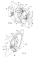
- Figure 1 shows a linear stapling machine 10 of rotary type provided with a stapling cylinder 11 in which two stapling modules 12, 12' situated in pairs after each other are mounted at the circumference of the stapling cylinder.
- the stapling cylinder is rotatably mounted to a base plate 45 for rotation around a first axis 13 around which the stapling cylinder is driven by driving means (not shown).
- the stapling cylinder 11 is furthermore parallel mounted in relation to a die cylinder 14, which is rotatable around a second axis 13' and against which the stapling cylinder rolls off.
- roll off' it is meant a co-operation between the cylinders 11, 14 where they have the same circumference speed in a stapling zone. Contact between the cylinders is not required.
- the stapling modules 12, 12' roll off against two dies 15, 15' mounted in the die cylinder 14 for final forming of a wire staple 25, Figure 2 .
- the printed product parts 16 run consisting of a plurality of paper layers that are to be stapled together into finished products.
- the product parts 16 that are to be stapled together consist either of a continuous material web that is cut off into finished products after stapling of the continuous product parts or of separate, already cut-off product units that are stapled into finished products in the stapler.
- the product parts consist of a continuous material web
- this can pass through the stapler at different degrees of enclosure of either cylinder.
- the product units consist of already cut-off product units, these entirely follow the surface of the die cylinder and are held on the surface of the die cylinder by pliers elements or pins.
- the stapling is intended to be effected when the stapling modules 12, 12' roll off against the dies 15, 15', which in the shown position in the figure occurs at the first stapling module 12.
- the stapling modules 12, 12' are provided with a respective stapling fork 21, 21' that carries a ready-formed wire staple 25, see Figure 2 , from a staple forming device 22, in the figure shown as a forming wheel, to the position when the wire staple, via a punch S mounted in the stapling cylinder 11, see Figure 2 , is forced through the material web 16 and finally formed against the die 15. Accordingly, the stapling is effected against the dies 15, 15' at the surface of the die cylinder.
- Both the stapling cylinder 11 and the die cylinder 14 rotate at a constant number of revolutions that corresponds to a circumference speed that is equal to the speed of the material web 16. Furthermore, a cutting assembly 40 is mounted adjacent to the stapling cylinder 11, which is provided with a first wire introduction assembly 41 and a second wire introduction assembly 42 that is arranged to advance wire 23 to a staple pick-up position.
- the zone for picking-up of staples is defined as a staple pick-up zone 31.
- a stapling zone 32 situated essentially at a displacement of half a revolution in relation to the staple pick-up zone. Said zones apply to the distance when no turning of the stapling fork is allowed.
- the stapling cylinder 11 with the stapling forks 21,21' and the cutting assembly 40 thereof are mounted to the base plate 45.
- Figure 2 shows a stapling fork 21 that holds a wire staple 25 that has been bent by the forming wheel 22 upon the passage of the stapling fork into at-shape having two branches 26 and a web 27.
- the wire staple is arranged to be forced through the material web by a punch S in the stapling fork.
- a corresponding wire staple for the second stapling fork has been analogously designated by a second wire staple 25', a second pair of branches 26', and a second web 27'.
- each wire staple is made by wire 23, from a coil of wire not shown, being advanced to a cutting position, whereupon cutting, picking-up and forming of the wire staple are effected when the stapling fork 21, 21' passes the cutting assembly 40 with the staple forming device 22 thereof, see Figure 1 .
- the wire staple is carried by the stapling fork 21 approximately half a revolution so as to encounter the die 15, the wire staple via the punch being forced through the product part 16 and formed against the die 15.
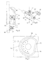
- FIG 3 shows in perspective the linear stapling machine 10 with the stapling cylinder 11 rotatable around the first axis 13.
- the stapling cylinder comprises the stapling modules 12, 12' that are identically constructed and therefore we only describe the first stapling module 12, the indexed numbered reference referring to the parts of the second stapling module 12'.
- the stapling module 12, 12' comprises a stapling head 50, 50' that is turnably mounted around a stapling main axis 35, 35'.
- the stapling head is provided with a stapling fork 21, 21' that is rotatably mounted in the stapling head 50, 50' around a stapling fork axis 61, 61' that is perpendicularly orientated in relation to the stapling main axis 35, 35'.
- the stapling fork is arranged with a cylindrical body 36, 36' rotatably in a corresponding cylindrical space in the stapling head.
- the cylindrical body is provided with a first guide means 37 by which the stapling fork 21, 21' can be turned around the stapling fork axis 61, 61' in the stapling head 50, 50'.
- the stapling head is further provided with a second guide means 38, 38' by which the stapling head together with the stapling fork can be turned in the stapling cylinder around the stapling main axis 35, 35'.
- the stapling cylinder 11 comprises a cam disc 39 provided with a primary third guide means 43 and a secondary third guide means 44, which third guide means are mounted adjacent to a respective stapling fork, Said third guide means 43, 44 are placed at each stapling fork but axially displaced to each other so that the primary third guide means 43 pushes away one of the wire introduction assemblies from the first stapling fork 21 and the other wire introduction assembly from the second stapling fork 21' when the stapling forks pass the cutting assembly 40.
- one of the stapling forks always picks up staple blanks from one of the wire introduction assemblies but never from the other one, while the other stapling fork always picks up staple blanks from the other wire introduction assembly but never from the one of them.
- the wire advancement can be kept constant and also be driven by only one motor.
- Figure 4 shows the corresponding view as in Figure 3 but with the stapling cylinder parts removed.
- the first guide means 37 of the cylindrical body 36, 36' comprises a first cam follower 46 mounted to a first turning arm 47, which cam follower 46 co-operates in the rotation of the stapling cylinder with a first cam curve 48 for a turning of the stapling fork 21 in the stapling head.
- the first guide means 37 provides a turning of the stapling fork by 90° during its motion to respective from the cutting assembly 40 outside the stapling zone and outside the staple pick-up zone so that the stapling fork before stapling in the stapling zone holds the wire staple with the web 27 thereof essentially parallel to the direction of motion of the product parts 16 and perpendicular in relation to the first axis 13.
- the first cam curve 48 is formed to change the position of the first cam follower 46 in directions parallel to the first axis 13 upon rotation around the first axis 13.
- the stapling fork When the stapling fork has delivered up the staple in the stapling zone, the stapling fork is turned back so that the stapling fork can fetch a new staple blank from the cutting assembly 40 in the staple pick-up zone.
- the staple blank is formed when it passes the forming wheel 22 whereupon a new turning of the stapling fork by 90' is effected when the same has left the staple pick-up zone and a new stapling cycle commences.
- the second guide means 38, 38' comprises a second cam follower 56, 56' mounted to a second turning arm 57, 57' connected to the stapling head 50, 50'.
- the cam follower runs guided by force in a second cam curve 58 that is formed to change the position of the second cam follower 56, 56' in directions perpendicular to the first axis 13.
- the first stapling head 50 is shown in a position for picking-up of a staple blank in the form of a cut-off length of wire, while the trailing second stapling head 50' has not yet reached this position.
- Figure 5 shows more clearly the first cam curve 48 that in the shown position, via the first cam follower, has turned the stapling fork by 90° in relation to the position of the stapling fork 21 that is shown in Figure 4 .
- the second cam curve 58 that guides the turning of the stapling head 50 is clearly shown in the figure. Both the first cam curve 48 and the second cam curve 58 are fixedly mounted to the base plate 45.
- the second cam curve 58 is formed to guide the second cam follower 56 by force in both directions, while the first cam curve 48 guides the first cam follower by force in both directions during a part of a revolution, while during the rest of the revolution, the first cam follower is spring actuated for the return into a rest position that is shown for the first cam follower 46 in Figure 4 .
- the stapling fork is actuated by a compression spring in order to press it out after the stapling.
- the stapling head is guided by force in the second cam curve 58.
- a compression spring that actuates the stapling fork
- a small sheet metal spring that engages the cylindrical body in the stapling head when it is not guided by the first cam curve 48.
- Figure 6 shows in planar view the position according to Figure 5 , the first stapling fork 21 having been turned to one end position thereof by the first cam curve 48 having actuated the first turning arm 47 with the cam follower thereof for the turning of the stapling fork 21.
- the figure also shows that the second stapling fork 21' has been turned approximately halfway toward the position of the first stapling fork.
- the cam followers 56, 56' of the two stapling heads 50, 50' follow all the time the second cam curve.
- Figure 7 shows the second cam curve 58 that during approximately half a revolution, where the stapling forks are in an initial stapling stage 71, a stapling stage 72, and a final stapling stage 73, is formed so that the stapling head with the stapling fork is aligned during the initial stapling stage 71 so that the web of the wire staple during the stapling stage 72 is held parallel to the die in the die cylinder and accordingly is turned in the stitching zone in order to allow the punch to force the wire staple at a right angle through the material web and in that connection simultaneously form the branches of the staple against the die.
- the stapling fork will be radially directed toward the die cylinder and the die during the stapling stage.
- the die can be fixedly formed in the die cylinder, which means a very simple and functional design of the die.
- the second cam curve 58 is circularly formed during a staple pick-up and staple forming stage 74.
- Figure 8 shows the stapling head 50 provided with the second turning arm 57 with the second cam follower 56 mounted.
- the stapling head will be turned around the stapling main axis 35.
- the stapling fork 21 is with the cylindrical body 36 thereof turnably arranged around the stapling fork axis 61 by the first turning arm 47 being fixedly arranged on the cylindrical body 36 and movable when the first cam follower 46 is guided by the first cam curve.
- Figure 9 shows the cylindrical body 36 with a first branch 21 A and a second branch 21 B arranged in the stapling fork 21. Furthermore, there is shown the fixedly mounted first turning arm 47 of the cylindrical body, Between the two branches 21 A , 21 B of the stapling fork, two permanent magnets 91, 92 are arranged in order to, together with the tightening force developed between the branches in the forming of the wire staple, contribute to the holding force of the wire staple when the same is carried from the staple forming phase until the staple is forced through the paper web and thereby is formed against the die.
- the first magnet 91 is placed at the first branch 21 A and the second magnet 92 is placed at the second branch 21 B , the magnets being placed symmetrically around an imaginary centre line, represented by the section line in Figure 9 , between the branches of the fork. Accordingly, this holding is a combination of magnet action and damping action.
- Other holding members for the staple are feasible, for instance, the staple may only by damping action be held by the stapling fork during the carriage from the staple pick-up zone to the stapling zone.
- Figure 10 shows the cylindrical body 36 in an axial section.
- a first cover plate 101 is mounted at one end of the body.
- the first turning arm 47 is fixedly connected, and on the turning arm, the first cam follower 46 is journalled,
- the other end of the body is dosed by a second cover plate 102 that is provided with a recess for the longitudinally moveable stapling fork 21 is mounted.
- a compression spring 103 is mounted inside the cylindrical body to bring back the longitudinally moveable stapling fork into a projected position after stapling has been carried out.
Landscapes
- Engineering & Computer Science (AREA)
- Textile Engineering (AREA)
- Mechanical Engineering (AREA)
- Life Sciences & Earth Sciences (AREA)
- Forests & Forestry (AREA)
- Folding Of Thin Sheet-Like Materials, Special Discharging Devices, And Others (AREA)
- Dovetailed Work, And Nailing Machines And Stapling Machines For Wood (AREA)
Applications Claiming Priority (1)
| Application Number | Priority Date | Filing Date | Title |
|---|---|---|---|
| SE0900548A SE534421C2 (sv) | 2009-04-23 | 2009-04-23 | Linjehäftningsmaskin av rotationstyp |
Publications (2)
| Publication Number | Publication Date |
|---|---|
| EP2246164A2 true EP2246164A2 (de) | 2010-11-03 |
| EP2246164A3 EP2246164A3 (de) | 2014-07-09 |
Family
ID=42357894
Family Applications (1)
| Application Number | Title | Priority Date | Filing Date |
|---|---|---|---|
| EP10160761.2A Withdrawn EP2246164A3 (de) | 2009-04-23 | 2010-04-22 | Rotative Mehrklammerheftmaschine |
Country Status (2)
| Country | Link |
|---|---|
| EP (1) | EP2246164A3 (de) |
| SE (1) | SE534421C2 (de) |
Cited By (1)
| Publication number | Priority date | Publication date | Assignee | Title |
|---|---|---|---|---|
| DE102012200877A1 (de) | 2012-01-23 | 2013-07-25 | Koenig & Bauer Aktiengesellschaft | Rollendruckmaschine und Verfahren mit einer Längshefteinrichtung zur Inline-Heftung sowie Verfahren zur Herstellung eines Produkte |
Citations (5)
| Publication number | Priority date | Publication date | Assignee | Title |
|---|---|---|---|---|
| US3762622A (en) | 1970-04-06 | 1973-10-02 | Tolerans Ab | Apparatus for stitching a continuously running web |
| DE2755209A1 (de) | 1977-12-10 | 1979-06-13 | Koenig & Bauer Ag | Drahtheftapparat |
| DE2755210A1 (de) | 1977-12-10 | 1979-06-13 | Koenig & Bauer Ag | Heftklammerschliessvorrichtung |
| US5474221A (en) | 1993-02-18 | 1995-12-12 | Tolerans Ingol Sweden Ab | Rotary stapling machine |
| EP0981450A1 (de) | 1997-05-07 | 2000-03-01 | Ferag AG | Vorrichtung zum längsheften von mehrteiligen druckereierzeugnissen |
Family Cites Families (3)
| Publication number | Priority date | Publication date | Assignee | Title |
|---|---|---|---|---|
| US615258A (en) * | 1898-12-06 | Printing machines | ||
| US2207413A (en) * | 1938-07-28 | 1940-07-09 | Hoe & Co R | Stapling mechanism |
| DE2835510C2 (de) * | 1978-08-12 | 1982-08-05 | Koenig & Bauer AG, 8700 Würzburg | Drahtheftvorrichtung |
-
2009
- 2009-04-23 SE SE0900548A patent/SE534421C2/sv unknown
-
2010
- 2010-04-22 EP EP10160761.2A patent/EP2246164A3/de not_active Withdrawn
Patent Citations (6)
| Publication number | Priority date | Publication date | Assignee | Title |
|---|---|---|---|---|
| US3762622A (en) | 1970-04-06 | 1973-10-02 | Tolerans Ab | Apparatus for stitching a continuously running web |
| DE2755209A1 (de) | 1977-12-10 | 1979-06-13 | Koenig & Bauer Ag | Drahtheftapparat |
| DE2755210A1 (de) | 1977-12-10 | 1979-06-13 | Koenig & Bauer Ag | Heftklammerschliessvorrichtung |
| US5474221A (en) | 1993-02-18 | 1995-12-12 | Tolerans Ingol Sweden Ab | Rotary stapling machine |
| US5690266A (en) | 1993-02-18 | 1997-11-25 | Tolerans Ingol Sweden Ab | Stapling device |
| EP0981450A1 (de) | 1997-05-07 | 2000-03-01 | Ferag AG | Vorrichtung zum längsheften von mehrteiligen druckereierzeugnissen |
Cited By (2)
| Publication number | Priority date | Publication date | Assignee | Title |
|---|---|---|---|---|
| DE102012200877A1 (de) | 2012-01-23 | 2013-07-25 | Koenig & Bauer Aktiengesellschaft | Rollendruckmaschine und Verfahren mit einer Längshefteinrichtung zur Inline-Heftung sowie Verfahren zur Herstellung eines Produkte |
| DE102012200877B4 (de) * | 2012-01-23 | 2014-09-11 | Koenig & Bauer Aktiengesellschaft | Rollendruckmaschine und Verfahren mit einer Längshefteinrichtung zur Inline-Heftung sowie Verfahren zur Herstellung eines Produktes |
Also Published As
| Publication number | Publication date |
|---|---|
| SE0900548A1 (sv) | 2010-10-24 |
| EP2246164A3 (de) | 2014-07-09 |
| SE534421C2 (sv) | 2011-08-16 |
Similar Documents
| Publication | Publication Date | Title |
|---|---|---|
| US8926486B2 (en) | Tool holding device and sheet-processing machine and folding carton gluer having the device | |
| US20070261576A1 (en) | Reel-fed rotary printing press | |
| EP2818312A1 (de) | Blattfaltvorrichtung und kartonformungsvorrichtung | |
| JPS5844585B2 (ja) | 輪転機の折たたみ装置 | |
| US8480068B2 (en) | Newspaper production apparatus | |
| PT1925579E (pt) | Dobradeira de facas com um sistema de dobragem mediante uma bolsa situado a montante da mesma e destinada à dobragem de folhas de material de impressão plano | |
| EP2582499B1 (de) | Maschine und verfahren zum hestellen von gedruckten produkten mit ausstanzungen an den rändern der blätter | |
| US20110098169A1 (en) | Method for producing a printed product | |
| US8955435B2 (en) | Method of producing print product and print product production device | |
| US5284466A (en) | Method and apparatus for fastening sheets of paper together with the aid of staples | |
| JP4943620B2 (ja) | 印刷機のためのロータリおよびジョー複合紙折り機 | |
| JP2004525797A (ja) | ステープル機構と一体化したシート収集機 | |
| US20100006617A1 (en) | Method and an apparatus in a rotary stapling machine | |
| EP2246164A2 (de) | Rotative Mehrklammerheftmaschine | |
| JP4136665B2 (ja) | シート方式の裁断をともなうブックレット・メーカ用の裁断システム | |
| JP2005537199A (ja) | 製本機および製本機の製造方法 | |
| US5390905A (en) | Apparatus for cutting and binding multi-layered printed products | |
| US20070252319A1 (en) | Method and Printing Machine for Producing a Printed Product with a Number of Inserts | |
| EP2246163A2 (de) | Drahtzuführvorrichtung in einer Rotationsheftmaschine | |
| US5772097A (en) | Binding device | |
| JP4646481B2 (ja) | 折り畳まれた印刷紙葉から形成された印刷物の背をステープルで綴じるための装置 | |
| EP2749514B1 (de) | Heftabschnitte einer kleinformatigen Zeitung | |
| JP2007245650A (ja) | 後処理装置 | |
| CN101848795A (zh) | 在折叠机中使用的具有多个切削元件的设备 | |
| JP4054429B2 (ja) | 紙容器及びこの紙容器の切欠形成装置 |
Legal Events
| Date | Code | Title | Description |
|---|---|---|---|
| PUAI | Public reference made under article 153(3) epc to a published international application that has entered the european phase |
Free format text: ORIGINAL CODE: 0009012 |
|
| AK | Designated contracting states |
Kind code of ref document: A2 Designated state(s): AT BE BG CH CY CZ DE DK EE ES FI FR GB GR HR HU IE IS IT LI LT LU LV MC MK MT NL NO PL PT RO SE SI SK SM TR |
|
| AX | Request for extension of the european patent |
Extension state: AL BA ME RS |
|
| RAP1 | Party data changed (applicant data changed or rights of an application transferred) |
Owner name: TOLERANS AB |
|
| PUAL | Search report despatched |
Free format text: ORIGINAL CODE: 0009013 |
|
| AK | Designated contracting states |
Kind code of ref document: A3 Designated state(s): AT BE BG CH CY CZ DE DK EE ES FI FR GB GR HR HU IE IS IT LI LT LU LV MC MK MT NL NO PL PT RO SE SI SK SM TR |
|
| AX | Request for extension of the european patent |
Extension state: AL BA ME RS |
|
| RIC1 | Information provided on ipc code assigned before grant |
Ipc: B42B 4/02 20060101ALI20140605BHEP Ipc: B41F 13/66 20060101ALN20140605BHEP Ipc: B27F 7/23 20060101AFI20140605BHEP |
|
| STAA | Information on the status of an ep patent application or granted ep patent |
Free format text: STATUS: THE APPLICATION HAS BEEN WITHDRAWN |
|
| 18W | Application withdrawn |
Effective date: 20141217 |