EP2246275B1 - Getriebe- und Führungsanordnung für Produkttrageplatten - Google Patents
Getriebe- und Führungsanordnung für Produkttrageplatten Download PDFInfo
- Publication number
- EP2246275B1 EP2246275B1 EP20100161518 EP10161518A EP2246275B1 EP 2246275 B1 EP2246275 B1 EP 2246275B1 EP 20100161518 EP20100161518 EP 20100161518 EP 10161518 A EP10161518 A EP 10161518A EP 2246275 B1 EP2246275 B1 EP 2246275B1
- Authority
- EP
- European Patent Office
- Prior art keywords
- transmission
- product carrier
- carrier plates
- support element
- curve
- Prior art date
- Legal status (The legal status is an assumption and is not a legal conclusion. Google has not performed a legal analysis and makes no representation as to the accuracy of the status listed.)
- Active
Links
Images
Classifications
-
- B—PERFORMING OPERATIONS; TRANSPORTING
- B65—CONVEYING; PACKING; STORING; HANDLING THIN OR FILAMENTARY MATERIAL
- B65G—TRANSPORT OR STORAGE DEVICES, e.g. CONVEYORS FOR LOADING OR TIPPING, SHOP CONVEYOR SYSTEMS OR PNEUMATIC TUBE CONVEYORS
- B65G17/00—Conveyors having an endless traction element, e.g. a chain, transmitting movement to a continuous or substantially-continuous load-carrying surface or to a series of individual load-carriers; Endless-chain conveyors in which the chains form the load-carrying surface
- B65G17/12—Conveyors having an endless traction element, e.g. a chain, transmitting movement to a continuous or substantially-continuous load-carrying surface or to a series of individual load-carriers; Endless-chain conveyors in which the chains form the load-carrying surface comprising a series of individual load-carriers fixed, or normally fixed, relative to traction element
- B65G17/123—Conveyors having an endless traction element, e.g. a chain, transmitting movement to a continuous or substantially-continuous load-carrying surface or to a series of individual load-carriers; Endless-chain conveyors in which the chains form the load-carrying surface comprising a series of individual load-carriers fixed, or normally fixed, relative to traction element arranged to keep the load-carriers horizontally during at least a part of the conveyor run
Definitions
- the present invention refers to a transmission and guide assembly for accompanying product carrier plates along a curve of a transfer path, in particular for accompanying chocolate moulds according to claim 1.
- Chocolate moulding systems include transfer systems with two parallel conveyor chains, which are wound on transmission cogwheels so as to define a path comprising a series of horizontal branches that are located one over the other and are connected by curves. This system is used, for example, to continuously move the moulds in areas where the chocolate is cooled.
- the sides of the chocolate moulds are hinged about respective horizontal axes to the two transport chains and run on fixed rails when travelling along the horizontal branches of the path.
- the moulds are accompanied so that they remain horizontal and always have the same face turned upwards.
- DE 2542906 discloses an assembly according to the preamble of claim 1.
- the purpose of the present invention is to create a transmission and guide assembly for accompanying product carrier plates along a curve of a transfer path, in particular for accompanying chocolate moulds, which fulfills the above requirement in a simple and economic manner.
- a transmission and guide assembly for accompanying product carrier plates along a curve of a transfer path, in particular for accompanying chocolate moulds, as defined in claim 1.
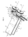
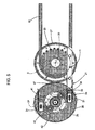
- the number 1 indicates the transmission and guide assembly which forms part of a conveyor 2, which transfers a series of product carrier plates 3 continuously along a path 4, comprising a series of horizontal branches 5 connected by curves 6.
- the product carrier plates 3 are defined, in particular, by moulds provided with upper chambers (not shown) into which the melted food product, for example chocolate, is poured.
- the conveyor 2 comprises two conveyor chains or belts 10 that are parallel to the path 4 and wound on transmission cogwheels 20 that define the curves 6.
- Figure 1 shows only one of the two conveyor chains or belts 10 and only one of the transmission cogwheels 20.
- the conveyor chains or belts 10 comprise a plurality of hinging means 11, for example, a plurality of horizontal pins which are spaced apart along the path 4 and define the respective hinge axes 12.
- the side edges of the product carrier plates 3 are indicated by reference number 14 and comprise respective central portions 15 that are hinged to the devices 11.
- the product carrier plates 3 oscillate about the axis 12 with respect to the conveyor chains or belts 10, but are kept horizontal so that the same side 16 is always facing upwards: along the branches 5, the side edges 14 slide against horizontal guides (not shown); along each curve 6, the assembly 1 comprises a guide device 21 associated with one of the two transmission cogwheels 20 of such curve.
- Such transmission cogwheel 20 rotates about an axis 22 that is fixed with respect to a support structure 23 (partially shown).
- the guide device 21 is arranged outside the curve 6 (that is, past the convex part of the curve 6) and comprises a support element defined, in particular, by a rocker arm 24, which has a central portion hinged to the support structure 23, so that it rotates about an axis 25.
- the axis 25 is parallel to and spaced apart from the axis 22 and is set at the same height as the axis 25.
- the rocker arm 24 is operated to rotate with the same angular velocity, in absolute value, as the transmission cogwheel 20, but in the opposite direction.
- a pair of gears 26, 27 are included to transmit and synchronize the rotational motion from the transmission cogwheel 20 to the rocker arm 24.
- the gears 26, 27 mesh with each other and are fixed and coaxial with respect to the rocker arm 24 and, respectively, to the pulley 20.
- the assembly 1 comprises two planetary or satellite wheels 31, which are hinged to diametrically opposite portions 32 of the rocker arm 24, so that they rotate about respective axes 33, parallel and eccentric with respect to the axis 25.
- the wheels 31 carry, in fixed positions, respective retention members defined by forks 34, configured in order to couple with the side edges 14 along at least part of the curve 6.
- the forks 34 define respective horizontal seats 35, which are pass-through parallel to the branches 5 and have their respective entrances 36 facing the path 4.
- Each fork 34 comprises an upper strip 37 and a lower strip 38, the ends of which, at the entrance 36, diverge (i.e. one is upwardly inclined and the other is downwardly inclined) so as to define a lead-in for a front edge 39 of the product carrier plates 3.
- the assembly 1 comprises a rotation device 40 to turn the wheels 31 with respect to the rocker arm 24, at the same angular velocity, in absolute value, and in the opposite direction.
- the preferred embodiment illustrated here is provided with a planetary gear reducer, so that the wheels 31 are defined by gears and the device 40 comprises a fixed solar gear 41, which is coaxial to the rocker arm 24, has the same diameter as the wheels 31 and is coupled to the wheels 31 by interposing idler gears 42 hinged to the rocker arm 24.
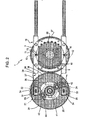
- the device 40 comprises a toothed transmission belt 45 wound on the external teeth of a fixed solar gear 41a, that replaces the solar gear 41, and on the external teeth of two satellite wheels 31a, that replace the wheels 31.
- the device 40 also comprises a plurality of tighteners 46 that are arranged at intervals between the wheels 41a and 31a and act on the back of the belt 45 to increase the winding angle of the belt 45 over the wheel 41a.
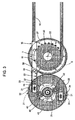
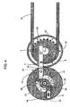
- the forks 34 take the product carrier plate 3 from the upper branch 5 ( Figures 2 and 3 ): one of the two side edges 14 automatically slides into the entrance 36, since the rotation of the rocker arm 24 is synchronized with that of the transmission cogwheel 20. After which, the side edge 14 slides into the seat 35 without difficulty, since the seat 35 remains horizontal ( Figures 4 and 5 ) during the synchronized rotation.
- the strips 37, 38 remain in contact with the product carrier plate 3, above and below the side edge 14, and accompany it to the lower branch 5, thereby maintaining the face 16 horizontal.
- the dimensions of the assembly 1 are designed so as to avoid interference between the product carrier plate 3, which is accompanied by one of the two forks 34, and the other fork 34 that remains momentarily empty.
- the assembly 1 achieves a high level of precision when positioning the forks 34 so that the carrier plates are accompanied with a high degree of precision and reliability. Furthermore, the use of a planetary gear reducer and of the gears 26,27 to transmit motion from the transmission cogwheel to the support element defined by the rocker arm 24 make it possible to limit maintenance of the assembly 1 and to maintain said assembly 1 compact.
- the transmission cogwheel 20 may be a driven wheel or a driving wheel of the conveyor 2; and/or the conveyor 2 and/or its product carrier plates 3 could be configured to carry solid or liquid foods other than chocolate (e.g. the product carrier plates could be defined by cheese moulds), or to transport non-food products (wax products, glass, etc ).
- the planetary gearing could have a solar gear defined by a wheel with internal cogs, instead of the wheel 41 with outer cogs; and/or the rocker arm 24 could be replaced by a differently-shaped support element, and/or operated by systems other than the gears 26, 27.
- the shape of the forks 34 could differ from that shown, and/or they could be replaced by different retention members, configured to perform the same function. Moreover, such retention members could be coupled to the satellite wheels to cushion any oscillations and facilitate the coupling of the product carrier plates 3.
- satellite wheels and retention members could be provided in device 21, based on the distance between the product carrier plates 3 mounted on the devices 11 along the conveyor chains or belts 10.
Landscapes
- Engineering & Computer Science (AREA)
- Mechanical Engineering (AREA)
- Confectionery (AREA)
Claims (10)
- Getriebe und Führungsanordnung (1) zum Begleiten von Produkttragplatten (3) längs einer Kurve (6) eines Übertragungspfads (4), insbesondere zur Begleitung von Schokoladenformen, wobei die Anordnung folgendes aufweist:- eine Tragstruktur (23);- ein Getriebezahnrad (20), welches sich bezüglich der Tragstruktur (23) um Abzuweichen, entlang der erwähnten Kurve (6), die Bewegung eines Transportbandes oder einer Kette (10) das bzw. das im Gebrauch um das Getriebezahnrad (20) gewunden ist und die Seitenkanten (14) der Produkttragplatten (3) angelenkt trägt; und- eine Führungsvorrichtung (21) um die Produkttragplatten (3) horizontal zu halten, während sie entlang der Kurve (6) laufen, wobei die Führungsvorrichtung folgendes aufweist:wobei das Halteglied (34) durch das erwähnte Satellitenrad (31) getragen wird, um zusammen mit dem Satellitenrad (31) zu rotieren oder sich zu drehen.a) ein Tragelement (24), welches sich bezüglich der erwähnten festen Tragstruktur um eine zweite Drehachse (25) parallel zu und beabstandet von der ersten Drehachse (22) drehen oder rotieren kann und derart betrieben wird, dass es sich mit der gleichen Winkelgeschwindigkeit in einem absoluten Wert dreht wie das Übertragungszahnrad (20), undb) mindestens ein Rückhalteglied (34) getragen von dem erwähnten Tragelement (24) und ausgebildet zum Eingriff mit den Produkttragplatten (3) entlang mindestens eines Teils der Kurve (6); dadurch gekennzeichnet, dass die Führungsvorrichtung (21) auch folgendes aufweist:- mindestens ein Satellitenrad (31) mit seiner Achse parallel und exzentrisch bezüglich der zweiten Drehachse (25) verlaufend und angelenkt an das erwähnte Tragelement (24), um sich so um seine eigene Achse (33) zu drehen, und- Drehmittel (40), um das erwähnte Satellitenrad (31) in Drehung zu versetzen, und zwar bezüglich des Tragelements (24) in entgegengesetzter Richtung und mit der gleichen Winkelgeschwindigkeit, in einem absoluten Wert;
- Anordnung nach Anspruch 1, dadurch gekennzeichnet, dass die erwähnten Dreh- oder Rotationsmittel (40) folgendes aufweisen:ein feststehendes Rad (41, 41 a) koaxial mit dem Tragelement (24), undKupplungsmittel (42, 45) zwischen dem erwähnten feststehenden Rad (41, 41 a) und dem erwähnten Satellitenrad (31, 31 a).
- Anordnung nach Anspruch 2, dadurch gekennzeichnet, dass das Satellitenrad (31) und das feststehende Rad (41) durch entsprechende Zahnräder definiert sind, und dass die Kupplungsmittel ein Zwischenzahnrad (42) aufweisen, angelenkt an das erwähnte Tragelement (24) und in Eingriff stehend mit dem Satellitenrad (31) und dem erwähnten feststehenden Rad (41).
- Anordnung nach Anspruch 2, dadurch gekennzeichnet, dass die Kupplungsmittel ein Zähne aufweisendes Band (45) umfassen, und zwar gewickelt um die Außenverzahnung des erwähnten feststehenden Rades (41 a) und das Satellitenrad (31 a).
- Anordnung nach einem der vorhergehenden Ansprüche, dadurch gekennzeichnet, dass das Tragelement (24) sich in eine entgegengesetzte Richtung bezüglich des Getriebezahnrads (24) dreht und dass die Führungsvorrichtung (21) außerhalb der erwähnten Kurve (6) angeordnet ist.
- Anordnung nach Anspruch 5, dadurch gekennzeichnet, dass zwei Zahnräder (26, 27) vorgesehen sind, und zwar integral und koaxial mit dem Tragelement (24) und, respektiv, mit dem Getriebezahnrad (20) und in Eingriff stehen miteinander, um die Drehbewegung von dem Getriebezahnrad (20) zu der zweiten Drehachse (25) zu übertragen.
- Anordnung nach einem der vorhergehenden Ansprüche, dadurch gekennzeichnet, dass das erwähnte Halteglied (34) einen oberen Teil (37) und einen unteren Teil (38) aufweist, und dazwischen einen Sitz (35) definierend, der ein Durchgang in Horizontalrichtung ist und einen zur erwähnten Kurve (6) hinweisenden Eingang (36) aufweist.
- Anordnung nach Anspruch 7, dadurch gekennzeichnet, dass die oberen und unteren Teile (37, 38) entsprechende Eingangsspitzen aufweisen, die nach oben bzw. unten derart geneigt sind, um eine Einführung für eine Kante (39) der Produkttragplatten (3) zu definieren.
- Eine Transportvorrichtung, die folgendes aufweist:- zwei Transportbänder oder -ketten (10), die parallel zueinander verlaufen und einen Übertragungspfad (4) definieren, der eine Vielzahl von horizontalen Zweigen (5) aufweist, die durch Kurven (6) miteinander verbunden sind, und wobei ferner Angelmittel (11) vorgesehen sind, und zwar beabstandet voneinander entlang des Übertragungspfades (4),- eine Vielzahl von Paaren von Getriebezahnrädern, die bezüglich der Tragstrukturen (23) um entsprechende erste Drehachsen (22) rotieren, um die Bewegung der erwähnten Transportbänder oder -ketten (10) entlang der erwähnten Kurven (6) abzulenken,- eine Vielzahl von Produkttragplatten (3), die Seitenteile (14) aufweisen, und zwar angelenkt an die erwähnten Anlenkmittel (11), um so um horizontale und gegenseitige parallele Anlenkachsen (12) zu schwingen, und- für mindestens einen Teil der Kurven (6) eine Getriebe- und Führungsanordnung (1) nach einem der vorhergehenden Ansprüche.
- Transportvorrichtung nach Anspruch 9, dadurch gekennzeichnet, dass die erwähnten Produkttragplatten (3) durch entsprechende Formen definiert sind, und zwar ausgestattet mit Formsitzen, die in der Lage sind gegossene, geschmolzene Nahrungsmittel aufzunehmen.
Applications Claiming Priority (1)
| Application Number | Priority Date | Filing Date | Title |
|---|---|---|---|
| ITTO2009A000344A IT1394004B1 (it) | 2009-04-30 | 2009-04-30 | Gruppo di rinvio e guida per accompagnare piastre di supporto prodotto lungo una curva di un percorso di trasferimento, in particolare per accompagnare stampi di modellatura di cioccolato |
Publications (2)
| Publication Number | Publication Date |
|---|---|
| EP2246275A1 EP2246275A1 (de) | 2010-11-03 |
| EP2246275B1 true EP2246275B1 (de) | 2013-06-12 |
Family
ID=41569676
Family Applications (1)
| Application Number | Title | Priority Date | Filing Date |
|---|---|---|---|
| EP20100161518 Active EP2246275B1 (de) | 2009-04-30 | 2010-04-29 | Getriebe- und Führungsanordnung für Produkttrageplatten |
Country Status (2)
| Country | Link |
|---|---|
| EP (1) | EP2246275B1 (de) |
| IT (1) | IT1394004B1 (de) |
Families Citing this family (3)
| Publication number | Priority date | Publication date | Assignee | Title |
|---|---|---|---|---|
| JP6281299B2 (ja) * | 2013-04-17 | 2018-02-21 | 中西金属工業株式会社 | スラットコンベア装置 |
| IT202000011269A1 (it) * | 2020-05-15 | 2021-11-15 | Sacmi Packaging & Chocolate S P A | Metodo e gruppo di ribaltamento per ruotare stampi contenenti prodotti alimentari da smodellare, in particolare prodotti in cioccolato |
| CN117048816A (zh) * | 2023-08-04 | 2023-11-14 | 上海钦龙科技设备有限公司 | 一种游乐设施中的游船承托装置 |
Family Cites Families (4)
| Publication number | Priority date | Publication date | Assignee | Title |
|---|---|---|---|---|
| US2965214A (en) * | 1956-06-05 | 1960-12-20 | Buehler Ag Geb | Hanger transfer device in particular in driers for long-size alimentary paste products |
| US3902590A (en) * | 1973-12-20 | 1975-09-02 | Rexnord Inc | Endless vertical conveyor system with gear pocket carrier guide |
| IT1038093B (it) * | 1975-05-14 | 1979-11-20 | Carle E Montanari Spa | Dispositivo per mantenere orizzontali gli stampi di colata per cioc colato nei punti di inversione del moto della catena di trasporto |
| IT1238183B (it) * | 1990-01-17 | 1993-07-09 | Carle & Montanari Spa | Disposizione di rinvio e di guida degli stampi di colata in impianti di modellatura di cioccolato |
-
2009
- 2009-04-30 IT ITTO2009A000344A patent/IT1394004B1/it active
-
2010
- 2010-04-29 EP EP20100161518 patent/EP2246275B1/de active Active
Also Published As
| Publication number | Publication date |
|---|---|
| ITTO20090344A1 (it) | 2010-11-01 |
| EP2246275A1 (de) | 2010-11-03 |
| IT1394004B1 (it) | 2012-05-17 |
Similar Documents
| Publication | Publication Date | Title |
|---|---|---|
| KR100290961B1 (ko) | 조정가능한포장기계용플라이트바시스템 | |
| EP2870088B1 (de) | Förderband mit artikelumleitung | |
| EP1849725A1 (de) | Förderer zum Transport und Aufstauen von einzelnen Produkten | |
| EP2246275A1 (de) | Getriebe- und Führungsanordnung für Produkttrageplatten | |
| CA3008143C (en) | Poultry belt drive | |
| JP5064285B2 (ja) | 搬送装置 | |
| EP2819937B1 (de) | Spiralförderer | |
| CN111989274A (zh) | 用于移动环形输送链的装置 | |
| KR101082596B1 (ko) | 떡 절단장치 | |
| ES2240648T3 (es) | Sistema de accionamiento para cintas transportadoras de eslabones modulares. | |
| CZ297114B6 (cs) | Dopravní zarízení | |
| US3292767A (en) | Processing machine feeding means | |
| US4986411A (en) | Continuous motion vertical conveyor | |
| CA2108076A1 (en) | Serpentine conveyors especially for automatic packaging machine | |
| US4174104A (en) | Conveyor for cards and similar articles | |
| EP4458160B1 (de) | Süsswarenformlinienvorrichtung | |
| ES2349615T3 (es) | Dispositivo de transporte extensible y sistema de transporte de alimentos que presenta el mismo. | |
| WO2008104798A1 (en) | Chain system | |
| RU2203203C2 (ru) | Упаковочная машина | |
| EP1818291B1 (de) | Pufferspeicher von variabler Kapazität mit von zwei parallelen Förderketten hängenden Regalen | |
| EP3339217B1 (de) | FÖRDERVORRICHTUNG FÜR EINE VERPACKUNGSMASCHINE FÜR TEIGWAREN, GRANULÖSE PRODUKTE
 UND DERGLEICHEN | |
| CN219383724U (zh) | 一种可调距输送线 | |
| CN109733806B (zh) | 一种追踪输送主体 | |
| CN213948947U (zh) | 蜡烛容器拨盘装置 | |
| US5341917A (en) | Timed retention conveying apparatus |
Legal Events
| Date | Code | Title | Description |
|---|---|---|---|
| PUAI | Public reference made under article 153(3) epc to a published international application that has entered the european phase |
Free format text: ORIGINAL CODE: 0009012 |
|
| AK | Designated contracting states |
Kind code of ref document: A1 Designated state(s): AT BE BG CH CY CZ DE DK EE ES FI FR GB GR HR HU IE IS IT LI LT LU LV MC MK MT NL NO PL PT RO SE SI SK SM TR |
|
| AX | Request for extension of the european patent |
Extension state: AL BA ME RS |
|
| 17P | Request for examination filed |
Effective date: 20110503 |
|
| 17Q | First examination report despatched |
Effective date: 20111011 |
|
| GRAP | Despatch of communication of intention to grant a patent |
Free format text: ORIGINAL CODE: EPIDOSNIGR1 |
|
| GRAP | Despatch of communication of intention to grant a patent |
Free format text: ORIGINAL CODE: EPIDOSNIGR1 |
|
| RAP1 | Party data changed (applicant data changed or rights of an application transferred) |
Owner name: CARLE & MONTANARI - OPM S.P.A. |
|
| GRAP | Despatch of communication of intention to grant a patent |
Free format text: ORIGINAL CODE: EPIDOSNIGR1 |
|
| GRAS | Grant fee paid |
Free format text: ORIGINAL CODE: EPIDOSNIGR3 |
|
| GRAA | (expected) grant |
Free format text: ORIGINAL CODE: 0009210 |
|
| AK | Designated contracting states |
Kind code of ref document: B1 Designated state(s): AT BE BG CH CY CZ DE DK EE ES FI FR GB GR HR HU IE IS IT LI LT LU LV MC MK MT NL NO PL PT RO SE SI SK SM TR |
|
| REG | Reference to a national code |
Ref country code: GB Ref legal event code: FG4D |
|
| REG | Reference to a national code |
Ref country code: CH Ref legal event code: EP |
|
| REG | Reference to a national code |
Ref country code: AT Ref legal event code: REF Ref document number: 616599 Country of ref document: AT Kind code of ref document: T Effective date: 20130615 |
|
| REG | Reference to a national code |
Ref country code: IE Ref legal event code: FG4D |
|
| REG | Reference to a national code |
Ref country code: DE Ref legal event code: R096 Ref document number: 602010007753 Country of ref document: DE Effective date: 20130808 |
|
| REG | Reference to a national code |
Ref country code: CH Ref legal event code: NV Representative=s name: ANDRE ROLAND S.A., CH |
|
| PG25 | Lapsed in a contracting state [announced via postgrant information from national office to epo] |
Ref country code: LT Free format text: LAPSE BECAUSE OF FAILURE TO SUBMIT A TRANSLATION OF THE DESCRIPTION OR TO PAY THE FEE WITHIN THE PRESCRIBED TIME-LIMIT Effective date: 20130612 Ref country code: SE Free format text: LAPSE BECAUSE OF FAILURE TO SUBMIT A TRANSLATION OF THE DESCRIPTION OR TO PAY THE FEE WITHIN THE PRESCRIBED TIME-LIMIT Effective date: 20130612 Ref country code: ES Free format text: LAPSE BECAUSE OF FAILURE TO SUBMIT A TRANSLATION OF THE DESCRIPTION OR TO PAY THE FEE WITHIN THE PRESCRIBED TIME-LIMIT Effective date: 20130923 Ref country code: GR Free format text: LAPSE BECAUSE OF FAILURE TO SUBMIT A TRANSLATION OF THE DESCRIPTION OR TO PAY THE FEE WITHIN THE PRESCRIBED TIME-LIMIT Effective date: 20130913 Ref country code: FI Free format text: LAPSE BECAUSE OF FAILURE TO SUBMIT A TRANSLATION OF THE DESCRIPTION OR TO PAY THE FEE WITHIN THE PRESCRIBED TIME-LIMIT Effective date: 20130612 Ref country code: NO Free format text: LAPSE BECAUSE OF FAILURE TO SUBMIT A TRANSLATION OF THE DESCRIPTION OR TO PAY THE FEE WITHIN THE PRESCRIBED TIME-LIMIT Effective date: 20130912 Ref country code: SI Free format text: LAPSE BECAUSE OF FAILURE TO SUBMIT A TRANSLATION OF THE DESCRIPTION OR TO PAY THE FEE WITHIN THE PRESCRIBED TIME-LIMIT Effective date: 20130612 |
|
| REG | Reference to a national code |
Ref country code: AT Ref legal event code: MK05 Ref document number: 616599 Country of ref document: AT Kind code of ref document: T Effective date: 20130612 |
|
| REG | Reference to a national code |
Ref country code: NL Ref legal event code: VDEP Effective date: 20130612 |
|
| REG | Reference to a national code |
Ref country code: LT Ref legal event code: MG4D |
|
| PG25 | Lapsed in a contracting state [announced via postgrant information from national office to epo] |
Ref country code: HR Free format text: LAPSE BECAUSE OF FAILURE TO SUBMIT A TRANSLATION OF THE DESCRIPTION OR TO PAY THE FEE WITHIN THE PRESCRIBED TIME-LIMIT Effective date: 20130612 Ref country code: BG Free format text: LAPSE BECAUSE OF FAILURE TO SUBMIT A TRANSLATION OF THE DESCRIPTION OR TO PAY THE FEE WITHIN THE PRESCRIBED TIME-LIMIT Effective date: 20130912 |
|
| PG25 | Lapsed in a contracting state [announced via postgrant information from national office to epo] |
Ref country code: LV Free format text: LAPSE BECAUSE OF FAILURE TO SUBMIT A TRANSLATION OF THE DESCRIPTION OR TO PAY THE FEE WITHIN THE PRESCRIBED TIME-LIMIT Effective date: 20130612 |
|
| PG25 | Lapsed in a contracting state [announced via postgrant information from national office to epo] |
Ref country code: IS Free format text: LAPSE BECAUSE OF FAILURE TO SUBMIT A TRANSLATION OF THE DESCRIPTION OR TO PAY THE FEE WITHIN THE PRESCRIBED TIME-LIMIT Effective date: 20131012 Ref country code: EE Free format text: LAPSE BECAUSE OF FAILURE TO SUBMIT A TRANSLATION OF THE DESCRIPTION OR TO PAY THE FEE WITHIN THE PRESCRIBED TIME-LIMIT Effective date: 20130612 Ref country code: PT Free format text: LAPSE BECAUSE OF FAILURE TO SUBMIT A TRANSLATION OF THE DESCRIPTION OR TO PAY THE FEE WITHIN THE PRESCRIBED TIME-LIMIT Effective date: 20131014 Ref country code: SK Free format text: LAPSE BECAUSE OF FAILURE TO SUBMIT A TRANSLATION OF THE DESCRIPTION OR TO PAY THE FEE WITHIN THE PRESCRIBED TIME-LIMIT Effective date: 20130612 Ref country code: CZ Free format text: LAPSE BECAUSE OF FAILURE TO SUBMIT A TRANSLATION OF THE DESCRIPTION OR TO PAY THE FEE WITHIN THE PRESCRIBED TIME-LIMIT Effective date: 20130612 Ref country code: AT Free format text: LAPSE BECAUSE OF FAILURE TO SUBMIT A TRANSLATION OF THE DESCRIPTION OR TO PAY THE FEE WITHIN THE PRESCRIBED TIME-LIMIT Effective date: 20130612 Ref country code: BE Free format text: LAPSE BECAUSE OF FAILURE TO SUBMIT A TRANSLATION OF THE DESCRIPTION OR TO PAY THE FEE WITHIN THE PRESCRIBED TIME-LIMIT Effective date: 20130612 |
|
| PG25 | Lapsed in a contracting state [announced via postgrant information from national office to epo] |
Ref country code: NL Free format text: LAPSE BECAUSE OF FAILURE TO SUBMIT A TRANSLATION OF THE DESCRIPTION OR TO PAY THE FEE WITHIN THE PRESCRIBED TIME-LIMIT Effective date: 20130612 Ref country code: RO Free format text: LAPSE BECAUSE OF FAILURE TO SUBMIT A TRANSLATION OF THE DESCRIPTION OR TO PAY THE FEE WITHIN THE PRESCRIBED TIME-LIMIT Effective date: 20130612 Ref country code: PL Free format text: LAPSE BECAUSE OF FAILURE TO SUBMIT A TRANSLATION OF THE DESCRIPTION OR TO PAY THE FEE WITHIN THE PRESCRIBED TIME-LIMIT Effective date: 20130612 |
|
| PLBE | No opposition filed within time limit |
Free format text: ORIGINAL CODE: 0009261 |
|
| STAA | Information on the status of an ep patent application or granted ep patent |
Free format text: STATUS: NO OPPOSITION FILED WITHIN TIME LIMIT |
|
| PG25 | Lapsed in a contracting state [announced via postgrant information from national office to epo] |
Ref country code: DK Free format text: LAPSE BECAUSE OF FAILURE TO SUBMIT A TRANSLATION OF THE DESCRIPTION OR TO PAY THE FEE WITHIN THE PRESCRIBED TIME-LIMIT Effective date: 20130612 |
|
| 26N | No opposition filed |
Effective date: 20140313 |
|
| PG25 | Lapsed in a contracting state [announced via postgrant information from national office to epo] |
Ref country code: IT Free format text: LAPSE BECAUSE OF FAILURE TO SUBMIT A TRANSLATION OF THE DESCRIPTION OR TO PAY THE FEE WITHIN THE PRESCRIBED TIME-LIMIT Effective date: 20130612 |
|
| REG | Reference to a national code |
Ref country code: DE Ref legal event code: R097 Ref document number: 602010007753 Country of ref document: DE Effective date: 20140313 |
|
| PG25 | Lapsed in a contracting state [announced via postgrant information from national office to epo] |
Ref country code: MC Free format text: LAPSE BECAUSE OF FAILURE TO SUBMIT A TRANSLATION OF THE DESCRIPTION OR TO PAY THE FEE WITHIN THE PRESCRIBED TIME-LIMIT Effective date: 20130612 Ref country code: LU Free format text: LAPSE BECAUSE OF FAILURE TO SUBMIT A TRANSLATION OF THE DESCRIPTION OR TO PAY THE FEE WITHIN THE PRESCRIBED TIME-LIMIT Effective date: 20140429 |
|
| GBPC | Gb: european patent ceased through non-payment of renewal fee |
Effective date: 20140429 |
|
| REG | Reference to a national code |
Ref country code: FR Ref legal event code: ST Effective date: 20141231 |
|
| REG | Reference to a national code |
Ref country code: IE Ref legal event code: MM4A |
|
| PG25 | Lapsed in a contracting state [announced via postgrant information from national office to epo] |
Ref country code: GB Free format text: LAPSE BECAUSE OF NON-PAYMENT OF DUE FEES Effective date: 20140429 |
|
| PG25 | Lapsed in a contracting state [announced via postgrant information from national office to epo] |
Ref country code: FR Free format text: LAPSE BECAUSE OF NON-PAYMENT OF DUE FEES Effective date: 20140430 |
|
| PG25 | Lapsed in a contracting state [announced via postgrant information from national office to epo] |
Ref country code: IE Free format text: LAPSE BECAUSE OF NON-PAYMENT OF DUE FEES Effective date: 20140429 |
|
| PG25 | Lapsed in a contracting state [announced via postgrant information from national office to epo] |
Ref country code: MT Free format text: LAPSE BECAUSE OF FAILURE TO SUBMIT A TRANSLATION OF THE DESCRIPTION OR TO PAY THE FEE WITHIN THE PRESCRIBED TIME-LIMIT Effective date: 20130612 |
|
| PG25 | Lapsed in a contracting state [announced via postgrant information from national office to epo] |
Ref country code: SM Free format text: LAPSE BECAUSE OF FAILURE TO SUBMIT A TRANSLATION OF THE DESCRIPTION OR TO PAY THE FEE WITHIN THE PRESCRIBED TIME-LIMIT Effective date: 20130612 |
|
| PG25 | Lapsed in a contracting state [announced via postgrant information from national office to epo] |
Ref country code: CY Free format text: LAPSE BECAUSE OF FAILURE TO SUBMIT A TRANSLATION OF THE DESCRIPTION OR TO PAY THE FEE WITHIN THE PRESCRIBED TIME-LIMIT Effective date: 20130612 |
|
| PG25 | Lapsed in a contracting state [announced via postgrant information from national office to epo] |
Ref country code: TR Free format text: LAPSE BECAUSE OF FAILURE TO SUBMIT A TRANSLATION OF THE DESCRIPTION OR TO PAY THE FEE WITHIN THE PRESCRIBED TIME-LIMIT Effective date: 20130612 Ref country code: HU Free format text: LAPSE BECAUSE OF FAILURE TO SUBMIT A TRANSLATION OF THE DESCRIPTION OR TO PAY THE FEE WITHIN THE PRESCRIBED TIME-LIMIT; INVALID AB INITIO Effective date: 20100429 |
|
| PG25 | Lapsed in a contracting state [announced via postgrant information from national office to epo] |
Ref country code: MK Free format text: LAPSE BECAUSE OF FAILURE TO SUBMIT A TRANSLATION OF THE DESCRIPTION OR TO PAY THE FEE WITHIN THE PRESCRIBED TIME-LIMIT Effective date: 20130612 |
|
| P01 | Opt-out of the competence of the unified patent court (upc) registered |
Effective date: 20230516 |
|
| PGFP | Annual fee paid to national office [announced via postgrant information from national office to epo] |
Ref country code: DE Payment date: 20250319 Year of fee payment: 16 |
|
| PGFP | Annual fee paid to national office [announced via postgrant information from national office to epo] |
Ref country code: CH Payment date: 20250501 Year of fee payment: 16 |
|
| REG | Reference to a national code |
Ref country code: CH Ref legal event code: U11 Free format text: ST27 STATUS EVENT CODE: U-0-0-U10-U11 (AS PROVIDED BY THE NATIONAL OFFICE) Effective date: 20260501 |