EP2246474A2 - Autobahnbrücke mit einem Verbindungsübergang - Google Patents
Autobahnbrücke mit einem Verbindungsübergang Download PDFInfo
- Publication number
- EP2246474A2 EP2246474A2 EP10161236A EP10161236A EP2246474A2 EP 2246474 A2 EP2246474 A2 EP 2246474A2 EP 10161236 A EP10161236 A EP 10161236A EP 10161236 A EP10161236 A EP 10161236A EP 2246474 A2 EP2246474 A2 EP 2246474A2
- Authority
- EP
- European Patent Office
- Prior art keywords
- joint
- substructure
- approximately
- transition
- plate
- Prior art date
- Legal status (The legal status is an assumption and is not a legal conclusion. Google has not performed a legal analysis and makes no representation as to the accuracy of the status listed.)
- Withdrawn
Links
- 230000007704 transition Effects 0.000 title claims abstract description 25
- 239000000463 material Substances 0.000 claims abstract description 25
- 239000010426 asphalt Substances 0.000 claims abstract description 18
- 229920001971 elastomer Polymers 0.000 claims abstract description 18
- 230000002787 reinforcement Effects 0.000 claims abstract description 13
- 239000002184 metal Substances 0.000 claims abstract description 10
- 238000011065 in-situ storage Methods 0.000 claims abstract description 8
- 239000000203 mixture Substances 0.000 claims abstract description 5
- 239000004744 fabric Substances 0.000 claims abstract description 4
- 239000003365 glass fiber Substances 0.000 claims abstract description 3
- 239000011384 asphalt concrete Substances 0.000 claims description 8
- 239000004567 concrete Substances 0.000 claims description 4
- 239000011230 binding agent Substances 0.000 claims description 2
- 239000010410 layer Substances 0.000 description 28
- 238000005266 casting Methods 0.000 description 9
- 150000001875 compounds Chemical class 0.000 description 7
- 239000000806 elastomer Substances 0.000 description 4
- 230000008602 contraction Effects 0.000 description 3
- -1 based on bitumen Chemical class 0.000 description 2
- 239000004593 Epoxy Substances 0.000 description 1
- 230000001464 adherent effect Effects 0.000 description 1
- 239000000853 adhesive Substances 0.000 description 1
- 230000001070 adhesive effect Effects 0.000 description 1
- 239000012790 adhesive layer Substances 0.000 description 1
- 239000003795 chemical substances by application Substances 0.000 description 1
- 238000013016 damping Methods 0.000 description 1
- 239000003822 epoxy resin Substances 0.000 description 1
- 239000000835 fiber Substances 0.000 description 1
- 239000012530 fluid Substances 0.000 description 1
- 239000006260 foam Substances 0.000 description 1
- 239000011521 glass Substances 0.000 description 1
- 239000008187 granular material Substances 0.000 description 1
- 229910052500 inorganic mineral Inorganic materials 0.000 description 1
- 238000004519 manufacturing process Methods 0.000 description 1
- 239000011707 mineral Substances 0.000 description 1
- 229920000647 polyepoxide Polymers 0.000 description 1
- 229920001296 polysiloxane Polymers 0.000 description 1
- 239000000565 sealant Substances 0.000 description 1
- 229920002994 synthetic fiber Polymers 0.000 description 1
- XLYOFNOQVPJJNP-UHFFFAOYSA-N water Substances O XLYOFNOQVPJJNP-UHFFFAOYSA-N 0.000 description 1
Images
Classifications
-
- E—FIXED CONSTRUCTIONS
- E01—CONSTRUCTION OF ROADS, RAILWAYS, OR BRIDGES
- E01D—CONSTRUCTION OF BRIDGES, ELEVATED ROADWAYS OR VIADUCTS; ASSEMBLY OF BRIDGES
- E01D19/00—Structural or constructional details of bridges
- E01D19/06—Arrangement, construction or bridging of expansion joints
- E01D19/067—Flat continuous joints cast in situ
Definitions
- This invention relates to a connection structure for components of a road surface, in particular to compensate deviations in expansion or contraction due to temperature changes.
- the invention can be applied to the joints or such transition structures in e.g. a viaduct, tunnel, or bridge, e.g. between the bridge deck and the foundation/mole.
- the pavement/road surface is with such a joint interrupted such that the deviation in expansion or contraction by the temperature change can be compensated by expansion and contraction, respectively, of the joint.
- joint transition is named joint transition.
- such a joint is filled with a curing or hardening casting compound, e.g. based on bitumen, to durably and at low price make the joint water tight and to keep the noise production of across the joint riding pneumatic tyres of cars and trucks as small as possible. In this manner a so called soft joint transition is obtained, contrary to a hard one.
- a curing or hardening casting compound e.g. based on bitumen
- DE 2.842.171 proposes to make the transition of a bloc shaped strip of an elastomer in which coils of metal wire are completely embedded. These coils are with their ends pull tight connected to a relevant to the component at the one and other, respectively, side of the joint fixed mounting part with the shape of a metal L-strip. These strips extend horizontally parallel to the joint length, thus normal to the driving direction, across the complete length of the transition, such that the transition crossing pneumatic tires make direct contact with these strips.
- EP 1.009.881 also discloses completely embedded coils of metal wire into the transition, which coils are with pre tension mounted to L-shaped strips at both sides of the joint, which strips end at sufficient distance below the top of the transition.
- FR 2.717.512 discloses application of a plurality mutual parallel and horizontal, parallel to the length of the joint, thus normal to the driving direction, extending, vertical strips of metal embedded in the transition and covered by a wear layer on top of which the tires roll.
- W096/24.726A discloses an expansion padding from a central part of bitumen and end parts of epoxy resin.
- US5.649.784A and US5.024.554A disclose a padding of a mixture of road-metal and curable fluid sealant.
- US5.171.100A discloses an expansion padding of a resilient central part and by plate parts thereof separated end parts of fibre reinforced epoxy.
- the object of the invention is to increase the durability of the transition in a different manner.
- the invention relates to a substructure of e.g. concrete and one or more of the following aspects: the substructure comprises two substantially in mutual extension provided parts which are mutually separated by a joint; the substructure is covered by a top layer of e.g. asphalt concrete, preferably ZOAB (very open asphalt concrete); the top layer is absent in the edge area's of the substructure at both sides of the joint; in said area the top layer is continued by a both parts of the substructure overlapping connection layer (transition) which preferably is partly made of e.g.
- a top layer e.g. asphalt concrete, preferably ZOAB (very open asphalt concrete
- the top layer is absent in the edge area's of the substructure at both sides of the joint
- the top layer is continued by a both parts of the substructure overlapping connection layer (transition) which preferably is partly made of e.g.
- bituminous material or a different cured or hardened casting compound such that the surface of the top layer and the surface of the connection layer provide a substantially continuous surface across which the pneumatic tires of cars and trucks roll; below the connection layer one of the edge area's of the substructure at both sides of the joint overlapping and preferably on both edge area's laying lower plate/joint plate/slab provided of preferably easily or supple foldable or pleadable sheet like material, such as of rubber or rubber like or elastomer material in preferably vulcanised state, which joint plate has e.g. a thickness between 1 and 10 millimetre, such as approx.
- the joint plate is substantially non-perforated in an area which extends across the joint; the joint plate is substantially flat or with pre-tension mounted by in its face, preferably crosswise of the joint, stretching in an amount of preferably at least 5%; the joint plate is fixedly connected to the one edge area or to both edge area's, e.g.
- the joint plate lays partly loose on one or both edge area's preferably in an area between the location of adhering connection to the edge area and the edge of the joint, wherein the loose laying area, related to the directing crosswise to the longitudinal direction of the joint, is preferably at least 5 cm;
- the connection layer has one, two or more prefabricated, above each other located plate like joint elements which are located o top of the possible joint plate; the one or more joint elements are adhered to each other and possibly to the joint plate and/or the substructure by preferably bituminous material; on top of the one or more joint elements there is a plate like cover part of which the top face is preferably level with the top face of the rest of the road surface such that the top face is uncovered and the cover part is recessed in the road surface while the cover part preferably has a non-adherent surface or a surface which is treated with release agent, such as silicone, such that it does
- a joint element can have indeed (preferably the upper joint element) or no (preferably the lower joint element) embedded reinforcement, which is preferably netlike and preferably made of an easily elastically stretchable material, like rubber or rubber like or elastomer material; a joint element contains a mixture of rubber or rubber like or elastomer material, road-metal and bitumen or a different binder; above the joint elements and the supporting beams there is a cover layer of which the top face is level with the top face of the upper layer and seamless connects to it.
- connection layer is e.g. at least 30 mm and/or not more than 200mm and is preferably between approx. 50 and 100mm.
- the invention can in particular be applied to a pavement with an open surface structure, such as ZOAB, made of asphalt concrete, e.g. made from two or more layers asphalt concrete of e.g. different type onto each other, such as a lower layer with a closed structure and on top of that a layer with an open structure.
- the open surface structure is e.g. obtained by applying a mixture of minerals with a granule size distribution around a mean.
- the connection layer is partly made in situ, preferably by castable or pourable material.
- connection layer/joint transition is protected in noise damping manner against early wear.
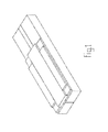
- the joint extends horizontally, perpendicular to the typical driving direction.
- the joint is at its top face covered by a prefabricated joint plate 6 with a thickness of 3 mm which by adhesive is fixedly mounted to both the foundation and the deck.
- a prefabricated joint plate 6 with a thickness of 3 mm which by adhesive is fixedly mounted to both the foundation and the deck.
- the plate 6 is parallel to itself according to the driving direction slightly expanded such that the plate 6 is nicely flat and tightly mounted.
- the joint plate 6 is illustrated at a distance above the parts 1 and 2.
- the plate 6 is located immediately on to op de parts 1 and 2, with an intermediate thin adhesive layer.
- the joint 7 is approx. 2 cm wide (the distance between the parts 1 and 2).
- the plate 6 is with parallel to the length of the joint 7 extending edge strips of approx. 2 or 3 cm wide to the parts 1 and 2 adhered, such that in the area between said edge strips the plate 6 is freely slidable located onto the parts 1 and 2.
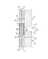
- the concrete substructure bears a pavement which in this example is made from two layers of asphalt, wherein the lower layer 4 is of the closed type and the upper layer is of the open type (ZOAB) 3.
- These cover layers are in the edge area's at both sides of the joint absent and replaced by a joint transition which provides with the cover layers a smooth driving face.
- the upper joint element 9 contains an embedded reinforcement net of rubber and the lower joint element is free from reinforcement.
- the reinforcement net is obtained by providing a rubber plate of 1 cm thick with oval perforations, wherein between the perforations remaining walls at the location of minimum wall thickness have a thickness of 1 cm.
- hot bitumen is cast onto it and, while the bitumen is still hot, the lower element 9 is installed, after which hot bitumen is cast again and, while the bitumen is still hot, the upper element 9 is installed, after which hot bitumen is cast again and, while the bitumen is still hot, the cover plate 8 is located on top.
- hot bitumen is cast onto parts 5 and 8 in a layer thickness of 5 to 10 millimetre, onto which a 4/8 road-metal is spread.
- the dimension of the parts 5 is 30 and of the parts 8 is 50 centimetre.
- the width of the joint plate 6 is smaller than that of the joint elements which have an equal width.
- the joint plate 6 has a width of 20 cm and the joint element has a width of 50 cm.
- the lower joint element is adhered to the substructure by e.g. bitumen.
- the element 8 is absent and to finish the structure initially shape free covering material is provided, e.g. casting compound poured, onto the top joint element and the supporting beams 5, such that they are covered by the casting compound and the top face of the casting compound merges seamlessly into the top face of part 3 to provide a complete driving face.
- initially shape free covering material e.g. casting compound poured, onto the top joint element and the supporting beams 5, such that they are covered by the casting compound and the top face of the casting compound merges seamlessly into the top face of part 3 to provide a complete driving face.
- joint 7 is at east partly filled with an easily yielding material, such as elastic foam of sponge like material, which is e.g. partly compressed and/or adhered to the side wall of the joint 7 and provides additional noise reduction.
- an easily yielding material such as elastic foam of sponge like material
- the joint plate 6 extends beyond the to the substructure adhered edge strips, thus is wider then the area between the adhered edge strips plus the width of the edge strips.
- the joint plate can be perforated such that in said area through the joint plate 6 the lower joint element is adhered to the substructure.
Landscapes
- Engineering & Computer Science (AREA)
- Architecture (AREA)
- Civil Engineering (AREA)
- Structural Engineering (AREA)
- Bridges Or Land Bridges (AREA)
- Road Paving Structures (AREA)
Applications Claiming Priority (2)
| Application Number | Priority Date | Filing Date | Title |
|---|---|---|---|
| NL2002830 | 2009-05-01 | ||
| NL2003886A NL2003886C2 (nl) | 2009-05-01 | 2009-11-30 | Met een voegovergang uitgeruste brug van een snelweg. |
Publications (2)
| Publication Number | Publication Date |
|---|---|
| EP2246474A2 true EP2246474A2 (de) | 2010-11-03 |
| EP2246474A3 EP2246474A3 (de) | 2015-07-01 |
Family
ID=42371394
Family Applications (1)
| Application Number | Title | Priority Date | Filing Date |
|---|---|---|---|
| EP10161236.4A Withdrawn EP2246474A3 (de) | 2009-05-01 | 2010-04-28 | Autobahnbrücke mit einem Verbindungsübergang |
Country Status (2)
| Country | Link |
|---|---|
| EP (1) | EP2246474A3 (de) |
| NL (1) | NL2003886C2 (de) |
Cited By (3)
| Publication number | Priority date | Publication date | Assignee | Title |
|---|---|---|---|---|
| CN103015315A (zh) * | 2012-12-19 | 2013-04-03 | 长安大学 | 一种提高桥梁抗风稳定性的方法 |
| CN111155424A (zh) * | 2020-01-10 | 2020-05-15 | 南通大学 | 一种混凝土桥面装配式伸缩装置及其制造方法 |
| CN112853913A (zh) * | 2021-01-14 | 2021-05-28 | 张义 | 一种水平拼接桥梁 |
Families Citing this family (4)
| Publication number | Priority date | Publication date | Assignee | Title |
|---|---|---|---|---|
| CN105442441A (zh) * | 2016-01-27 | 2016-03-30 | 江苏三川智能科技有限公司 | 一种桥梁伸缩缝装置 |
| RU2655126C1 (ru) * | 2017-07-21 | 2018-05-23 | Акционерное общество "Спецремпроект" | Деформационный шов плитно-балочного моста |
| RU2734389C1 (ru) * | 2020-01-28 | 2020-10-15 | Акционерное общество "Спецремпроект" | Деформационный шов балочного моста |
| CN112681123A (zh) * | 2020-12-18 | 2021-04-20 | 江苏领跑梦毛勒智造科技集团有限公司 | 环保伸缩装置及其安装方法 |
Citations (7)
| Publication number | Priority date | Publication date | Assignee | Title |
|---|---|---|---|---|
| DE2842171B1 (de) | 1978-09-28 | 1979-06-28 | Kober Ag | Abdeckung ueber Dehnungsfugen in Verkehrswegen,insbesondere Bruecken |
| US5024554A (en) | 1990-02-22 | 1991-06-18 | Koch Materials Company | Bridge joint construction |
| US5171100A (en) | 1990-12-12 | 1992-12-15 | Bergstedt Jan Eric O | Preformed expansion joint system |
| FR2717512A1 (fr) | 1994-03-21 | 1995-09-22 | Chapuis Philippe | Joint de chaussée à feuilles. |
| WO1996024726A1 (en) | 1995-02-09 | 1996-08-15 | Prismo Limited | Asphaltic plug expansion joint with flexible nosing |
| US5649784A (en) | 1995-06-16 | 1997-07-22 | Pavetech International, Inc. | Expansion joint system and method of making |
| EP1009881A1 (de) | 1997-08-28 | 2000-06-21 | RSAG Reparatur- und Sanierungstechnik AG | Verbindungskonstruktion für bauteile und verfahren zur herstellung der verbindungskonstruktion |
-
2009
- 2009-11-30 NL NL2003886A patent/NL2003886C2/nl not_active IP Right Cessation
-
2010
- 2010-04-28 EP EP10161236.4A patent/EP2246474A3/de not_active Withdrawn
Patent Citations (7)
| Publication number | Priority date | Publication date | Assignee | Title |
|---|---|---|---|---|
| DE2842171B1 (de) | 1978-09-28 | 1979-06-28 | Kober Ag | Abdeckung ueber Dehnungsfugen in Verkehrswegen,insbesondere Bruecken |
| US5024554A (en) | 1990-02-22 | 1991-06-18 | Koch Materials Company | Bridge joint construction |
| US5171100A (en) | 1990-12-12 | 1992-12-15 | Bergstedt Jan Eric O | Preformed expansion joint system |
| FR2717512A1 (fr) | 1994-03-21 | 1995-09-22 | Chapuis Philippe | Joint de chaussée à feuilles. |
| WO1996024726A1 (en) | 1995-02-09 | 1996-08-15 | Prismo Limited | Asphaltic plug expansion joint with flexible nosing |
| US5649784A (en) | 1995-06-16 | 1997-07-22 | Pavetech International, Inc. | Expansion joint system and method of making |
| EP1009881A1 (de) | 1997-08-28 | 2000-06-21 | RSAG Reparatur- und Sanierungstechnik AG | Verbindungskonstruktion für bauteile und verfahren zur herstellung der verbindungskonstruktion |
Cited By (5)
| Publication number | Priority date | Publication date | Assignee | Title |
|---|---|---|---|---|
| CN103015315A (zh) * | 2012-12-19 | 2013-04-03 | 长安大学 | 一种提高桥梁抗风稳定性的方法 |
| CN103015315B (zh) * | 2012-12-19 | 2015-10-28 | 长安大学 | 一种提高桥梁抗风稳定性的方法 |
| CN111155424A (zh) * | 2020-01-10 | 2020-05-15 | 南通大学 | 一种混凝土桥面装配式伸缩装置及其制造方法 |
| CN112853913A (zh) * | 2021-01-14 | 2021-05-28 | 张义 | 一种水平拼接桥梁 |
| CN112853913B (zh) * | 2021-01-14 | 2022-11-18 | 中铁二十五局集团第五工程有限公司 | 一种水平拼接桥梁 |
Also Published As
| Publication number | Publication date |
|---|---|
| EP2246474A3 (de) | 2015-07-01 |
| NL2003886C2 (nl) | 2010-11-09 |
Similar Documents
| Publication | Publication Date | Title |
|---|---|---|
| EP2246474A2 (de) | Autobahnbrücke mit einem Verbindungsübergang | |
| RU2558557C2 (ru) | Устройство для перекрытия компенсационного зазора | |
| JP5852353B2 (ja) | 橋梁に用いる伸縮装置及びその製造方法 | |
| KR101174256B1 (ko) | 지하차도 구조물의 신축이음부 포장층 연결부재 및 포장층 시공방법 | |
| CA2832030C (en) | Integrated ballast mat | |
| JP5113003B2 (ja) | 舗装構造及び舗装体の形成方法 | |
| US3308725A (en) | Paving element and paving employing the same | |
| KR20170082318A (ko) | 탄성복원형 신축이음장치 및 그 시공방법 | |
| JP4452818B2 (ja) | 橋梁における伸縮継手部の樋補修方法 | |
| KR20100089616A (ko) | 보강망을 구비한 신축이음 | |
| CN106498849B (zh) | 一种桥梁伸缩缝及其施工工艺 | |
| KR20190112451A (ko) | 탄성보강재를 이용하여 내구성을 향상시킨 신축이음 시공방법 | |
| KR102701744B1 (ko) | 보강재가 매립된 고무패드를 이용한 부직포 일체형 침목패드, 그 제작 및 시공 방법 | |
| KR101560189B1 (ko) | 키 형상을 활용한 강성 포장도로의 신축이음구조 및 시공방법 | |
| JP2015067982A (ja) | 道路橋梁用ゴムコンクリートとその施工方法及び道路橋梁用ゴムコンクリートを用いた伸縮装置 | |
| JP2013144894A (ja) | 伸縮装置用止水材 | |
| JP4927681B2 (ja) | 舗装構造 | |
| JP3941875B2 (ja) | 橋梁床版の遊間における継手構造 | |
| CZ297844B6 (cs) | Tlumicí profil pro kolejnice | |
| RU2032786C1 (ru) | Деформационный шов | |
| JP5620687B2 (ja) | 橋梁に用いる伸縮装置及びその製造方法 | |
| JP2004084463A (ja) | 伸縮継手装置 | |
| JP3789412B2 (ja) | 道路橋の埋設型ジョイント用の埋設継手及び道路橋の埋設型ジョイント | |
| KR101360788B1 (ko) | 연결부재를 이용한 구조물의 이음부 시공공법 | |
| JPH0632961Y2 (ja) | 道路ジョイント |
Legal Events
| Date | Code | Title | Description |
|---|---|---|---|
| PUAI | Public reference made under article 153(3) epc to a published international application that has entered the european phase |
Free format text: ORIGINAL CODE: 0009012 |
|
| AK | Designated contracting states |
Kind code of ref document: A2 Designated state(s): AT BE BG CH CY CZ DE DK EE ES FI FR GB GR HR HU IE IS IT LI LT LU LV MC MK MT NL NO PL PT RO SE SI SK SM TR |
|
| AX | Request for extension of the european patent |
Extension state: AL BA ME RS |
|
| PUAL | Search report despatched |
Free format text: ORIGINAL CODE: 0009013 |
|
| AK | Designated contracting states |
Kind code of ref document: A3 Designated state(s): AT BE BG CH CY CZ DE DK EE ES FI FR GB GR HR HU IE IS IT LI LT LU LV MC MK MT NL NO PL PT RO SE SI SK SM TR |
|
| AX | Request for extension of the european patent |
Extension state: AL BA ME RS |
|
| RIC1 | Information provided on ipc code assigned before grant |
Ipc: E01D 19/06 20060101AFI20150528BHEP |
|
| STAA | Information on the status of an ep patent application or granted ep patent |
Free format text: STATUS: THE APPLICATION IS DEEMED TO BE WITHDRAWN |
|
| 18D | Application deemed to be withdrawn |
Effective date: 20160105 |