EP2246533A1 - Gleitelement und verfahren zur behandlung der oberfläche des gleitelements - Google Patents
Gleitelement und verfahren zur behandlung der oberfläche des gleitelements Download PDFInfo
- Publication number
- EP2246533A1 EP2246533A1 EP09705288A EP09705288A EP2246533A1 EP 2246533 A1 EP2246533 A1 EP 2246533A1 EP 09705288 A EP09705288 A EP 09705288A EP 09705288 A EP09705288 A EP 09705288A EP 2246533 A1 EP2246533 A1 EP 2246533A1
- Authority
- EP
- European Patent Office
- Prior art keywords
- hard particles
- top face
- sliding member
- abrasion resistance
- valve
- Prior art date
- Legal status (The legal status is an assumption and is not a legal conclusion. Google has not performed a legal analysis and makes no representation as to the accuracy of the status listed.)
- Granted
Links
Images


Classifications
-
- F—MECHANICAL ENGINEERING; LIGHTING; HEATING; WEAPONS; BLASTING
- F01—MACHINES OR ENGINES IN GENERAL; ENGINE PLANTS IN GENERAL; STEAM ENGINES
- F01L—CYCLICALLY OPERATING VALVES FOR MACHINES OR ENGINES
- F01L1/00—Valve-gear or valve arrangements, e.g. lift-valve gear
- F01L1/02—Valve drive
- F01L1/04—Valve drive by means of cams, camshafts, cam discs, eccentrics or the like
- F01L1/047—Camshafts
- F01L1/053—Camshafts overhead type
-
- C—CHEMISTRY; METALLURGY
- C23—COATING METALLIC MATERIAL; COATING MATERIAL WITH METALLIC MATERIAL; CHEMICAL SURFACE TREATMENT; DIFFUSION TREATMENT OF METALLIC MATERIAL; COATING BY VACUUM EVAPORATION, BY SPUTTERING, BY ION IMPLANTATION OR BY CHEMICAL VAPOUR DEPOSITION, IN GENERAL; INHIBITING CORROSION OF METALLIC MATERIAL OR INCRUSTATION IN GENERAL
- C23C—COATING METALLIC MATERIAL; COATING MATERIAL WITH METALLIC MATERIAL; SURFACE TREATMENT OF METALLIC MATERIAL BY DIFFUSION INTO THE SURFACE, BY CHEMICAL CONVERSION OR SUBSTITUTION; COATING BY VACUUM EVAPORATION, BY SPUTTERING, BY ION IMPLANTATION OR BY CHEMICAL VAPOUR DEPOSITION, IN GENERAL
- C23C8/00—Solid state diffusion of only non-metal elements into metallic material surfaces; Chemical surface treatment of metallic material by reaction of the surface with a reactive gas, leaving reaction products of surface material in the coating, e.g. conversion coatings, passivation of metals
- C23C8/02—Pretreatment of the material to be coated
-
- C—CHEMISTRY; METALLURGY
- C23—COATING METALLIC MATERIAL; COATING MATERIAL WITH METALLIC MATERIAL; CHEMICAL SURFACE TREATMENT; DIFFUSION TREATMENT OF METALLIC MATERIAL; COATING BY VACUUM EVAPORATION, BY SPUTTERING, BY ION IMPLANTATION OR BY CHEMICAL VAPOUR DEPOSITION, IN GENERAL; INHIBITING CORROSION OF METALLIC MATERIAL OR INCRUSTATION IN GENERAL
- C23C—COATING METALLIC MATERIAL; COATING MATERIAL WITH METALLIC MATERIAL; SURFACE TREATMENT OF METALLIC MATERIAL BY DIFFUSION INTO THE SURFACE, BY CHEMICAL CONVERSION OR SUBSTITUTION; COATING BY VACUUM EVAPORATION, BY SPUTTERING, BY ION IMPLANTATION OR BY CHEMICAL VAPOUR DEPOSITION, IN GENERAL
- C23C8/00—Solid state diffusion of only non-metal elements into metallic material surfaces; Chemical surface treatment of metallic material by reaction of the surface with a reactive gas, leaving reaction products of surface material in the coating, e.g. conversion coatings, passivation of metals
- C23C8/06—Solid state diffusion of only non-metal elements into metallic material surfaces; Chemical surface treatment of metallic material by reaction of the surface with a reactive gas, leaving reaction products of surface material in the coating, e.g. conversion coatings, passivation of metals using gases
- C23C8/08—Solid state diffusion of only non-metal elements into metallic material surfaces; Chemical surface treatment of metallic material by reaction of the surface with a reactive gas, leaving reaction products of surface material in the coating, e.g. conversion coatings, passivation of metals using gases only one element being applied
- C23C8/24—Nitriding
- C23C8/26—Nitriding of ferrous surfaces
-
- F—MECHANICAL ENGINEERING; LIGHTING; HEATING; WEAPONS; BLASTING
- F01—MACHINES OR ENGINES IN GENERAL; ENGINE PLANTS IN GENERAL; STEAM ENGINES
- F01L—CYCLICALLY OPERATING VALVES FOR MACHINES OR ENGINES
- F01L1/00—Valve-gear or valve arrangements, e.g. lift-valve gear
- F01L1/12—Transmitting gear between valve drive and valve
- F01L1/14—Tappets; Push rods
- F01L1/143—Tappets; Push rods for use with overhead camshafts
-
- F—MECHANICAL ENGINEERING; LIGHTING; HEATING; WEAPONS; BLASTING
- F01—MACHINES OR ENGINES IN GENERAL; ENGINE PLANTS IN GENERAL; STEAM ENGINES
- F01L—CYCLICALLY OPERATING VALVES FOR MACHINES OR ENGINES
- F01L1/00—Valve-gear or valve arrangements, e.g. lift-valve gear
- F01L1/12—Transmitting gear between valve drive and valve
- F01L1/18—Rocking arms or levers
- F01L1/181—Centre pivot rocking arms
-
- F—MECHANICAL ENGINEERING; LIGHTING; HEATING; WEAPONS; BLASTING
- F16—ENGINEERING ELEMENTS AND UNITS; GENERAL MEASURES FOR PRODUCING AND MAINTAINING EFFECTIVE FUNCTIONING OF MACHINES OR INSTALLATIONS; THERMAL INSULATION IN GENERAL
- F16H—GEARING
- F16H53/00—Cams or cam-followers, e.g. rollers for gearing mechanisms
- F16H53/06—Cam-followers
-
- F—MECHANICAL ENGINEERING; LIGHTING; HEATING; WEAPONS; BLASTING
- F01—MACHINES OR ENGINES IN GENERAL; ENGINE PLANTS IN GENERAL; STEAM ENGINES
- F01L—CYCLICALLY OPERATING VALVES FOR MACHINES OR ENGINES
- F01L1/00—Valve-gear or valve arrangements, e.g. lift-valve gear
- F01L1/12—Transmitting gear between valve drive and valve
- F01L1/14—Tappets; Push rods
- F01L1/16—Silencing impact; Reducing wear
-
- F—MECHANICAL ENGINEERING; LIGHTING; HEATING; WEAPONS; BLASTING
- F01—MACHINES OR ENGINES IN GENERAL; ENGINE PLANTS IN GENERAL; STEAM ENGINES
- F01L—CYCLICALLY OPERATING VALVES FOR MACHINES OR ENGINES
- F01L2301/00—Using particular materials
Definitions
- the present invention relates to a sliding member used for an internal combustion engine, and a surface treatment method for the sliding member.
- Sliding members have been recently used under a high-load environment in internal combustion engines which have been developed to further increase power and rotational speed. Therefore, the sliding members are required to be further enhanced in abrasion resistance. Therefore, the present invention has an object to enhance abrasion resistance in sliding members used in internal combustion engines, etc. which are increased in power and rotational speed.
- a sliding member used in an internal combustion engine is characterized in that hard particles having higher hardness than the sliding member are dispersed on the surface of the sliding member and the surface dispersed with the hard particles is subjected to a nitriding treatment.
- the surface dispersed with the hard particles is subjected to the nitriding treatment, whereby a nitride layer containing the hard particles is formed on the surface.
- the nitride layer is increased in abrasion resistance because base material of the sliding member is nitrided, and further the abrasion resistance is further enhanced because the hard particles are contained. Accordingly, the nitride layer having the high abrasion resistance is formed on the sliding member, whereby the abrasion resistance of the sliding member can be enhanced.
- the hard particles may be particles of aluminum oxide.
- the hard particles of aluminum oxide dispersed on the surface of the sliding member have good chemistry with the nitriding treatment, and thus the hard particles are easily contained in the nitride layer generated through the nitriding treatment. Therefore, the nitride layer which is enhanced in abrasion resistance because it contains the hard particles can be easily formed on the surface of the sliding member, thereby enhancing the abrasion resistance of the sliding member.
- the particles of aluminum oxide are high in hardness and low in cost, and thus there is an advantage that the cost can be reduced and the abrasion resistance can be enhanced.
- the hard particles may be particles having a particle diameter of 10 ⁇ m(micrometer) or less.
- the particle diameter of the hard particles contained in the nitride layer is small, and unevenness of the surface of the nitride layer is suppressed, and frictional loss on the surface which is subjected to the nitriding treatment can be reduced.
- the hard particles may be dispersed on the surface so that the density of the hard particles on the surface is equal to at least 5%, and subjected to the nitriding treatment. In this case, a sufficient amount of hard particles can be contained in the nitride layer, and thus the abrasion resistance of the nitride layer can be enhanced.
- the sliding surface of the sliding member with another member may be polished by the hard particles, and further subjected to the nitriding treatment.
- a sliding surface of the sliding member with the other member is polished by the hard particles, whereby the surface roughness of the sliding surface is smoothed, and the frictional loss on the sliding surface can be reduced.
- polishing is executed by the hard particles, the hard particles impinge against or bite into the sliding surface of the sliding member, whereby recesses are formed on the sliding surface.
- the recesses function as oil pits when the siding member is installed in the internal combustion engine.
- the oil pits can be formed in a polishing step of smoothing the sliding surface of the sliding member, and thus a step of forming oil pits is not separately required. Therefore, there is an advantage that the number of steps can be reduced.
- the sliding member may be a valve lifter which slides with another member in an internal combustion engine to open/close an engine valve.
- a nitride layer having excellent abrasion resistance is formed on the surface of a valve lifter to which a high load is imposed in an internal combustion engine which has been recently further increased in power and rotational speed, whereby the abrasion resistance of the valve lifter can be enhanced.
- the surface treatment method of the sliding member according to the present invention which is used for an internal combustion engine is characterized by comprising: a step of dispersing hard particles having higher hardness than the sliding member on the surface of the sliding member; and a step of conducting a nitriding treatment on the surface on which the hard particles are dispersed.
- the nitriding treatment is conducted on the surface on which the hard particles are dispersed, whereby a nitride layer containing the hard particles is formed on the surface.
- the nitride layer is enhanced in abrasion resistance because the base material of the sliding member is nitrided, and further it is further enhanced because it contains the hard particles. Accordingly, the nitride layer having high abrasion resistance can be formed on the sliding member, and the abrasion resistance of the sliding member can be enhanced.
- the sliding member may be a valve lifter which slides with another member in the internal combustion engine to open/close an engine valve
- the step of dispersing the hard particles on the surface of the sliding member may contain a step of polishing the sliding surface sliding with the other member with the hard particles.
- the abrasion resistance of a valve lifter to which a high load is applied in an internal combustion engine which has been recently developed to further increase in power and rotational speed can be enhanced.
- the sliding surface is polished by the hard particles, so that the surface roughness of the sliding surface can be smoothed, the abrasion loss on the sliding surface can be reduced and the hard particles can be efficiently dispersed on the sliding surface.
- the polishing is executed by the hard particles, the hard particles impinge against or bite into the sliding surface of the valve lifter to form recesses on the sliding surface of the valve lifter, and the recesses function as oil pits when the sliding member is installed in the internal combustion engine. Accordingly, in the polishing step, the sliding surface of the valve lifter is smoothed and the oil pits are formed. Accordingly, it is not required to separately provide a step of forming oil pits, and thus the number of processing steps can be reduced.
- the nitriding treatment is conducted on the surface on which the hard particles are dispersed, whereby the nitride layer which contains the hard particles and has high abrasion resistance is formed on the surface of the sliding member, and thus the abrasion resistance of the sliding member can be enhanced.
- the hard particles are used particles of aluminum oxide which has good chemistry with the nitriding treatment. Therefore, the hard particles can be easily contained in the nitride layer generated in the nitriding treatment, and the nitriding layer which sufficiently contains the hard particles can be easily generated on the surface of the sliding member. Furthermore, the abrasion resistance of the surface of the sliding member can be enhanced while suppressing increase of the cost.
- the particle diameter of the hard particles is set to 10 ⁇ m or less, whereby unevenness of the nitriding layer can be suppressed and the frictional loss of the surface which is subjected to the nitriding treatment can be reduced. Furthermore, the hard particles are dispersed on the surface of the sliding member so that the density of the hard particles on the surface occupies at least 5%, whereby a sufficient amount of hard particles can be contained in the nitride layer, and the abrasion resistance of the nitride layer can be enhanced.
- the sliding surface between the sliding member and another member is polished by the hard particles, and also the nitriding treatment is conducted, whereby the surface roughness of the sliding surface can be smoothed and the frictional loss on the sliding surface can be reduced.
- polishing when polishing is executed, recesses functioning as oil pits can be formed on the sliding surface of the sliding member by the hard particles, and thus the number of processing steps can be reduced.
- the sliding member is a valve lifter which slides with another member in an internal combustion engine to open/close the engine valve
- a nitride layer having an excellent abrasion resistance is formed on the surface of a valve lifter to which a high load is applied in an internal combustion engine which has been recently developed to further increase in power and rotational speed, whereby the abrasion resistance of the valve lifter can be enhanced.
- Fig. 1 is a cross-sectional view showing an example of an internal combustion engine 100 according to an embodiment.
- the internal combustion engine 100 according to the embodiment has a cylinder block 1, and a cylinder head 2 secured to the cylinder block 1 through a head gasket 10.
- a cylinder 11 is formed in the cylinder block 1, a piston 12 which is fitted in the cylinder 11 so as to be slidable upward and downward, and the piston 12 is continuously joined to a crank shaft (not shown) which is supported through a shaft on the cylinder block 1 so as to be freely rotatable.
- Water jackets 13 and 14 for making cooling water flow to cool the cylinder block 1 are formed on the cylinder block 1 so as to surround the piston 1.
- the cylinder head 2 is provided with a combustion chamber 20 at the upper portion of the cylinder 11, and also provided with an air intake port 21 and an exhaust port 22 which intercommunicate with the combustion chamber 20.
- the air intake port 21 and the exhaust port 22 are opened and closed by an air intake valve 3 and an exhaust valve 4 respective as described later.
- air-fuel mixture containing mixture of fuel and air sucked from the air intake port 21 is compressed in the combustion chamber 20 formed between the piston 12 and the cylinder head 2, and ignited by an ignition plug (not shown) to be combusted.
- the combustion pressure pushes the piston 12 downward, and the push pressure rotationally drives the crank shaft.
- the piston 12 After the combustion, the piston 12 is upwardly moved by the rotation of the crank shaft under the state that the exhaust port 22 is opened by the exhaust valve 4, thereby compressing the combustion chamber 20 between the piston 12 and the cylinder head 2, whereby exhaust gas is discharged from the combustion chamber 20 to the exhaust port 22.
- Water jackets 23, 24 and 25 for cooling the cylinder head 2 are formed in the cylinder head 2 so as to surround the air intake port 21 and the exhaust port 22. These water jackets 23, 24 and 25 serve as flow paths through which cooling liquid flows into the cylinder head 2.
- the air intake valve 3 (engine valve) for opening/closing the air intake port 21 is disposed in the cylinder head 2 so as to be urged by a valve spring 3a in a direction along which the air intake port 21 is closed (valve closing direction)
- the exhaust valve 4 (engine valve) for opening/closing the exhaust port 22 is disposed in the cylinder head 2 so as to be urged by a valve spring 4a in a direction along which the exhaust port 22 is closed (valve closing direction).
- the air intake valve 3 has a round rod-like stem 30 and a substantially conical umbrella portion 31 which is integrally formed at the top of the stem 30.
- the air intake valve 3 is disposed in a substantially cylindrical valve guide 26 engagedly fitted in the cylinder head 2 so as to project to some midpoint of the air intake port 21 so that the stem 30 thereof penetrates through the valve guide 26, whereby the air intake valve 3 is supported freely slidably by the valve guide 26.
- the upper portion of the valve spring 3a and a cylindrical valve lifter 6 having a bottom (sliding member) are covered on the top portion of the stem 30, and the upper portion of the stem 30 is brought into contact with the cam shaft 7 through the valve lifter 6.
- the exhaust valve 4 has a rounded rod-like stem 40 and a substantially conical umbrella portion 41 formed integrally at the tip of the stem 40 as in the case of the air intake valve 3.
- the exhaust valve 4 is disposed in a substantially cylindrical valve guide 27 engagedly fitted in the cylinder head 2 so as to project to some midpoint of the exhaust port 22 so that the stem 40 thereof penetrates through the valve guide 26, whereby the exhaust valve 4 is supported freely slidably by the valve guide 27.
- a valve sprint 4a is mounted on the stem 40, and the end portion of a locker arm 80 described later abuts against the top portion of the stem 40.
- Ring-shaped valve seals 21a and 22a are arranged at the combustion chamber 20 side of the air intake port 21 and the exhaust port 22 respectively.
- the outer peripheral edge portion of the umbrella portion 31 of the air intake valve 3 and the valve seal 21a form a seal face to thereby close the air intake port 21.
- the outer peripheral edge portion of the umbrella portion 41 of the exhaust valve 4 and the valve seal 22a form a seal face, thereby closing the exhaust port 22.
- the internal combustion engine 100 has a unicam type valve operating device 5 driven by one cam shaft 7, and the air intake valve 3 and the exhaust valve 4 are opened/closed by the valve operating device 5.
- the valve operating device 5 has a cam shaft 7 which is supported through a shaft in the cylinder head at the upper portion of the air intake valve 3 so as to be freely movable, and a locker shaft 8 which has an axial line parallel to the cam shaft 7 and is fixed to the cylinder head 2.
- the cam shaft 7 is joined to the crank shaft by a chain power transmission mechanism (not shown), and rotates interlockingly with the crank shaft.
- the cam shaft 7 is provided with substantially disc-shaped air intake cam 70 and exhaust cam 71, the peripheral surface of the air intake cam 70 is brought into contact with the top face 61 of the valve lifter 6, and the peripheral surface of the exhaust cam 71 is brought into contact with a locker arm 80 which is disposed so as to be freely rotated around the locker shaft 8.
- the air intake valve 3 moves upward and downward through the valve lifter 6 in accordance with the cross-section (profile) of the air intake cam 70
- the exhaust valve 4 moves upward and downward through the locker arm 80 in accordance with the profile of the exhaust cam 71, and the air intake port 21 and the exhaust port 22 are opened at a proper timing.
- the locker arm 80 is supported by the locker shaft 8 so as to be freely rotatable.
- One end of the locker arm 80 is provided with a roller 81 which comes into rolling contact with the exhaust cam 7, and a tappet screw 82 which comes into contact with the top portion of the stem 40 of the exhaust valve 4 is threadedly fitted to the other end of the locker arm 80 so that the forward/backward position can be adjusted.
- the locker arm 80 rotates around the locker shaft 8 in connection with rotation of the exhaust cam 71, and pushes the exhaust valve 4 through the tappet screw 82, thereby opening/closing the exhaust valve 4.
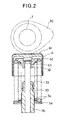
- Fig. 2 is a cross-sectional view showing a main part of the construction of the valve lifter 6 and its neighborhood.
- a valve stem seal 33 for keeping air tightness between the stem 30 and the valve guide 26 is disposed at the upper end of the valve guide 26.
- the valve guide 26 is provided with a spring seat 34 for positioning the lower end of the valve spring 3a.
- the spring seat 34 is brought into contact with the cylinder head 2 as shown in Fig. 1 to fixedly hold the lower end of the valve spring 3a.
- a retainer 32 for holding the upper end of the valve spring 3a is secured to the top portion of the stem 30 through a cotter 63, and the retainer 32 receives the urging force of the valve spring 3a, whereby the air intake valve 3 is urged in the valve closing direction.
- a cylindrical valve lifter 6 having a bottom is covered on the top portion of the stem 30 with the bottom surface thereof placed face up, and the top portion of the stem 30 is brought into contact with the inside of the bottom surface of the valve lifter 6 through a shim 62.
- the top face 61 of the valve lifter 6 is brought into contact with the peripheral surface of the air intake cam 70 by the urging force of the valve spring 3a, and when the air intake cam 70 pushes the valve lifter 6 against the urging force of the valve spring 3a in connection with the rotation of the cam shaft 7, the air intake valve 3 is pushed down together with the valve lifter 6, and moved in the valve opening direction.
- the interval between the valve lifter 6 and the air intake cam 70 is adjustable by changing the thickness of the shim 62. Furthermore, the edge of the top face 61 is chamfered.
- the top face 61 of the valve lifter 6 slides with the peripheral surface of the air intake cam 70 at all times.
- relatively high surface pressure occurs between the top face 61 and the peripheral surface of the air intake cam 70. Therefore, iron or the like which has excellent resistance to surface pressure is used as the material of the top face 61 of the valve lifter 6, and furthermore a surface treatment is conducted on the top face 61 to enhance the abrasion resistance.
- the surface treatment of the top face 61 will be described.
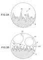
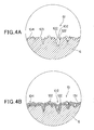
- Figs. 3 and 4 are diagrams schematically showing the surface treatment of the valve lifter 6 according to the first embodiment
- Fig. 3A is an enlarged view showing a surface state before a polishing step (first step described later)
- Fig. 3B is an enlarged view showing the surface state during the polishing step
- Fig. 4A is an enlarged view showing the surface state after the polishing step
- Fig. 4B is an enlarged view showing the surface state after a nitriding treatment (second step described later).
- Figs. 3 and 4 and Figs. 6 to 8 described later are greatly enlarged views showing the microstructure on the surface of the top face 61, and a part thereof is schematically diagramed.
- the valve lifter 6 is cut out from an iron type material which is formed into a substantially cylindrical shape by casting, forging or drawing process or an iron type material which is formed into a cup-like shape having a bottom by casting or forging.
- a space in which the stem 30, the valve spring 3a, etc. are mounted is formed by lathe turning, and the top face 61 is processed to be flat by grinding. As shown in Fig. 3A , the top face 61 after the grinding process becomes a smoothed surface, however, when it is greatly enlarged, existence of projections 101 and recess portions 102 are observed.
- the surface treatment of the top face 61 in the first embodiment is executed according to the following procedure.
- the top face 61 having unevenness as shown in Fig. 3A is polished so as to become a high-level smooth surface.
- hardparticles having higher hardness than the base material (for example, the iron type material described above) constituting the top face 61 is used as polishing material.
- a barrel device, preferably a wet type vibration barrel device may be used as a device of polishing the top surface.
- iron, steel, stainless, iron type alloy or the like may be used as material having excellent resistance to surface pressure as described above. It is desired that the hard particles have higher hardness than the material (base material) constituting the top face 61.
- particles of alumina aluminum oxide
- particles of alumna type ceramic containing other elements or a lot of oxygen in the composition of alumina particles of zirconia type ceramics, particles of silicon carbide type ceramics may be used.
- alumina has sufficiently high hardness and is lower in cost as compared with zirconia, etc. , for example. Therefore, alumina is used as dominant material from the viewpoint that desired abrasion resistance can be enhanced without causing great increase of the cost.
- the base material of the top face 61 is a cut-difficult material such as steel having high hardness or the like
- superabrasive material such as false diamond, CBN (cubical crystal boron nitride) or the like
- Silica silicon oxide
- the particle diameter of the hard particles is preferably equal to 10 ⁇ m or less, and more preferably set to 5 ⁇ m or less. The reason for this will be described later.
- a mixture of two kinds of hard particles different in particle diameter that is, 1mm (millimeter) or more in particle size, for example, large hard particles 121 of 3mm, and small hard particles 122 of 10 ⁇ m or less in particle diameter is used.
- the measurement of the hard particle diameter may be performed by using a particle size distribution measuring device; produced by Nikkiso Co., Ltd. MICROTRACK HRA 9320-X100.
- the hard particles 121 shown in Fig. 3B are spherical particles of about 3mm in particle diameter, for example. However, the size and shape thereof may be arbitrary, and the particles may have an incisive shape.
- the contraction scale of Fig. 3B is different from that of Figs. 3A , 4A and 4B .
- the projecting portions 101 existing at the top face 61 are scraped by the hard particles 121 and 122, and thus the top face 61 is gradually smoothened.
- the large hard particles 121 grind the projecting portions 101.
- the projecting portions 101 are also ground by the hard particles 122 having the small particle size in the first step, and the top face 61 is trimmed to be flat. Furthermore, during polishing shown in Fig. 3B , the hard particles 122 are pushed into the top face 61 by the hard particles 121, etc., so that the hard particles 122 bite into the top face 61.
- the projecting portions 101 ( Fig. 3A, Fig. 3B ) existing on the surface of the top face 61 are scraped and thus a flat surface 103 is formed. Furthermore, many hard particles 122 (10 ⁇ m or less) used for polishing or many hard particles 122 (10 ⁇ m or less) occurring due to impingement of the respective hard particles for polishing are disposed on the surface of the top face 61, and adhere to the whole top face 61 containing the insides of the recess portions 102, the flat surface 103, etc.
- the hard particles 122 contain hard particles smaller than 10 ⁇ m in particle diameter (for example, particles having the particle diameter of 5 ⁇ m or less, or the particle diameter of 1 to 2 ⁇ m) generated by the impingement of the respective hard particles.
- the hard particles shown in Fig. 4A are incisive particles, however, most of particles excellent in cutting power such as alumina or the like have incise shapes as shown in Fig. 4A . Therefore, some hard particles 122 bite into the surface layer of the top face 61.
- recess portions 104 which do not exist before the first step may occur on the surface of the top face 61. These recess portions 104 occur when the hard particles 122 impinge during polishing or when the hard particles 122 biting into the top face 61 during polishing drop out during polishing or after polishing. As described above, in addition to the recess portions 102 existing before the first step, recess portions 104 are newly formed at places where the projection portions 101 exist in the first step, and thus many small recesses exist on the surface of the top face 61.
- These recess portions 102 and 104 on the top face 61 function as oil pool (oil pits) for holding lubricating oil when the valve lifter 6 is installed in the internal combustion engine 100, and thus they are useful.
- the top face 61 of the valve lifter 6 slides with the peripheral surface of the air intake cam 70 ( Fig. 2 ) at high speed. Therefore, oil is supplied from the external during operation and this oil forms oil film on the top face 61 to lubricate the top face 61 and the peripheral surface of the air intake cam 70.
- the recess portions 102 and 104 described above function as oil pits, so that high oil holding force is exercised on the top face 61 and the top face 61 and the peripheral surface of the air intake cam 70 are lubricated.
- the recess portions 104 are formed in addition to the recession portions 102 which have existed from the first.
- the main recess portions 102 and 104 functioning as oil pits are provided on the top face 61, and high oil holding force is exercised. Therefore, the valve lifter 6 and the air intake cam 70 can be lubricated.
- the oil pits are formed when the top face 61 is polished in the first step, and thus there is an advantage that a processing for forming oil pits separately is unnecessary and the number of processing steps can be reduced.
- the nitriding treatment is conducted.
- This nitriding treatment is executed by a gas nitriding method, a gas soft nitriding method, a salt bath nitriding method, an ion nitriding method or the like, however, a specific method may be determined in accordance with the type of the base material constituting the top face 61 or the like. It is preferable as an example of the nitriding treatment to using a gas soft nitriding furnace as a nitriding treatment device and executes low-temperature soft nitriding. As shown in Fig.
- a nitriding layer 131 is formed on the surface layer of the top face 61 as shown in Fig. 4B .
- the nitriding layer 131 is a layer containing as main components iron nitride generated by nitriding the base material (the iron type material described above) constituting the top face 61 or nitride of other elements containing in the base material of the valve lifter 6.
- the nitride layer 131 is formed in the direction from the surface layer of the top face 61 to the inside of the base material, grows to the outside of the surface layer of the top face 61, and wraps at least some of the hard particles 122.
- the nitride layer 131 containing the hard particles 122 are formed on the surface of the top face 61.
- the hard particles 122 are formed of alumina, particularly it has good chemistry with the nitriding treatment, and thus there is an advantage that the nitride layer 131 easily grows while containing the hard particles 122, and many hard particles 122 are taken into the nitride layer 131.
- the nitride layer 131 formed in the second step has high hardness and excellent abrasion resistance because the base material constituting the top face 61 is nitrided. Therefore, the abrasion resistance of the top surface which slides with the air intake cam 70 at high speed is enhanced, and thus the valve lifter 6 having excellent endurance can be implemented. Furthermore, as shown in Fig. 4B , the nitride layer 131 formed in the second step contains the hard particles 122 having high hardness, and thus the enhancement of the abrasion resistance can be implemented in cooperation with the high abrasion resistance of the nitride layer 131 obtained by nitriding the base material of the valve lifter 6.
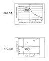
- Fig. 5 is a graph showing the abrasion resistance obtained by the surface treatment according to the first embodiment, wherein Fig. 5A is a graph showing the correlation between the particle diameter and the abrasion resistance, and Fig. 5B is a graph showing the correlation between the density of the hard particles and the abrasion resistance.
- the data shown in Figs. 5A and 5B are data obtained by actually conducting the surface treatment of the top face 61 according to the above method as the surface treatment method of the first embodiment. Whether the abrasion resistance is good or not is determined by estimating a scuffing-occurring limit according to an actual machine motoring test.
- Fig. 5A shows the correlation between the particle diameter and the abrasion resistance after the nitriding treatment when the surface treatment of the top face 61 was tested by using as hard particles 122 alumina which was different in particle diameter.
- the abscissa axis of the graph of Fig. 5A represents the particle diameter of the hard particles 122.
- the ordinate axis represents the abrasion resistance of the surface after the nitriding treatment.
- hard particles of one kind of particle diameter were used as the hard particles 122 in one test. The test was conducted by using five kinds of hard particles of 1 ⁇ m, 5 ⁇ m, 10 ⁇ m, 15 ⁇ m and 20 ⁇ m in particle diameter.
- values of preferable abrasion resistance are represented by a broken line. If abrasion resistance stronger than this broken line is obtained, the particle diameter would be preferable.
- an index value representing the abrasion resistance in the case of the particle size of 1 ⁇ m, an index value representing the abrasion resistance in the case of the particle size of 5 ⁇ m, and an index value representing the abrasion resistance in the case of the particle size of 10 ⁇ m were higher than a predetermined index of the abrasion resistance, and an index value representing the abrasion resistance in the case of the particle size of 15 ⁇ m and an index value representing the abrasion resistance in the case of the particle size of 20 ⁇ m were lower than the predetermined index of the abrasion resistance. That is, as shown in Fig.
- the particle size of the hard particles 122 dispersed on the top face 61 before the nitriding treatment of the second step is preferably equal to 10 ⁇ m or less, and more preferably equal to 5 ⁇ m or less. It is preferable that particles of 10 ⁇ m or less in particle diameter are dispersed on the surface of the sliding member as described above. However, when all particles to be dispersed on the surface of the sliding member are manufactured to be less than 1 ⁇ m in particle diameter, the manufacturing time is greatly increased, and this is not favorable on mass production.
- hard particles 122 are used.
- the particle size of the hard particles 122 is preferably equal to 10 ⁇ m, more preferably 5 ⁇ m, these hard particles 122 are difficult to drop out, and easily taken into the nitriding layer 131.
- Fig. 5B shows the correlation between the amount of the hard particles 122 dispersed on the top face 61 before the nitriding treatment and the abrasion resistance after the nitriding treatment when the test of the surface treatment of the top face 61 was executed by using alumina having a predetermined particle diameter is used as the hard particles 122.
- the abscissa axis of the graph of Fig. 5B represents the index value representing the abrasion resistance obtained by the test. It is expected that the abrasion resistance is higher as the value of the abscissa axis is higher.
- a preferable value of the abrasion resistance is represented by a broken line, and if a value higher than the value represented by the broken line is obtained, this would be a preferable result.
- an index value representing the abrasion resistance in the case of 1%, an index value representing the abrasion resistance in the case of 1.2% and an index value representing the abrasion resistance in the case of 3.8% were lower than a predetermined index of the abrasion resistance, and an index value representing the abrasion resistance in the case of 6.4%, an index value representing the abrasion resistance in the case of 8.9, an index value representing the abrasion resistance in the case of 14.3%, an index value representing the abrasion resistance in the case of 15.2% and an index value representing the abrasion resistance in the case of 16.7% were higher than the predetermined index of the abrasion resistance.
- the density of 5% is regarded as a reasonable boundary value.
- the density of the hard particles is higher, the abrasion resistance is higher.
- the manufacturing time is greatly increased, and thus this is not favorable on mass production.
- the measurement of the density of the hard particles in this test was executed by using X-ray photoelectron analyzer: ESCA-1000 produced by Shimadzu Corporation while measured at about 40nm below the surface.
- the amount of the hard particles 122 to be dispersed on the top face 61 before the nitriding treatment of the second step is preferably equal to at least 5% or more.
- the hard particles 122 are dispersed onto the top face 61 and subjected to the nitriding treatment, whereby the nitride layer 131 having high abrasion resistance containing the hard particles 122 is formed, and this can enhance the abrasion resistance of the valve lifter 6, and particularly enhance the abrasion resistance of the top face 61 of the valve lifter 6 which slides with the air intake cam 70 and to which a high load is applied in an internal combustion engine which has been recently developed to further increase in power and rotational speed.
- the hard particles 122 are easily contained in the nitride layer 131, and the nitride layer which sufficiently contains the hard particles 122 can be easily formed on the top face 61.
- the particle diameter of the hard particles 122 is set to 10 ⁇ m or less, whereby the unevenness of the nitride layer 131 can be suppressed and the frictional loss of the top face 61 can be reduced. Furthermore, the hard particles 122 are dispersed on the top face 61 so as to occupy the density of at least 5%, and then the nitriding treatment is conducted, thereby enhancing the abrasion resistance of the nitride layer 131. Furthermore, the particle size of the hard particles 122 to be dispersed on the top face 61 before the nitriding treatment is preferably equal to 10 ⁇ m or less, more preferably 5 ⁇ m. Furthermore, the amount of the hard particles 122 to be dispersed on the top face 61 before the nitriding treatment is preferably equal to 5% or more in density of the top face 61.
- the hard particles 121 having a large particle diameter (for example, 1mm or more, preferably 3mm or more) and the small hard particles 122 (10 ⁇ m or less) are used. Therefore, the nitriding treatment is conducted in the second step under the state that these small hard particles 122 adhere to the top face 61. Therefore, there is an advantage that polishing can be efficiently and quickly performed by the large hard particles having strong cutting force in the first step, and also there is an advantage that the hard particles 122 bite into the surface layer of the top face 61 and thus the small recess portions 104 can be formed, thereby forming effective oil pits.
- the projecting portions (the projecting portions 101 of Fig.
- the hard particles having a large particle diameter for example, 1mm or more, preferably 3mm or more.
- the hard particles 122 are easily taken into the nitride layer 131, and thus a larger amount of hard particles can be contained in the nitride layer 131.
- the hard particles 122 hardly drop out from the nitride layer 131, and thus the nitride layer 131 having more excellent abrasion resistance can be formed.
- the hard particles 122 are used together with the hard particles 121 having a large particle diameter (1mm or more), and thus the hard particles 122 are pushed into the top face 61 by the hard particles 121. Therefore, the hard particles 122 bite into the top face 61, or minute oil pits are formed. Accordingly, the sliding environment of the top face 61 can be adjusted. As described above, by using the hard particles different in particle diameter, an excellent effect can be obtained in each of the first and second steps. When the hard particles different in particle diameter are used as described above the particle diameter of at least the small hard particles 122 is preferably set to 10 ⁇ m or less as described above.
- the mixture of the large hard particles 121 (1mm or more) and the small hard particles 122 (10 ⁇ m or less) which are formed of alumina or the like is used in the first step.
- the present invention is not limited to this style, and for example only the large hard particles (1mm or more) having one kind of particle diameter may be used. Even when only the large hard particles are used, the hard particles impinge against one another and come into contact with one another under pressure, and thus they are destructed/crushed, so that hard particles having a smaller particle diameter similar to the hard particles 122 occur. Therefore, even when the surface treatment of the first step is conducted by using only the large hard particles 121, the same situation as the case where the small hard particles 122 are mixed in the first embodiment is established, and thus a sufficient effect can be obtained.
- alumina may be used for the small hard particles 122 and particles formed of any material such as metal material, synthetic rubber or the like may be used as the large hard particles 121.
- the polishing is efficiently executed by the hard particles 121, and a desired surface state can be created.
- the nitride layer 131 is formedwhile containing the small hard particles 122 formed of alumina or the like, and thus high abrasion resistance can be implemented as in the case of the first embodiment.
- FIG. 6 is a schematic diagram showing an example of the surface state of the valve lifter 6 according to the second embodiment, wherein Fig. 6A is an enlarged view showing the surface state before the nitriding treatment (a second step described later), and Fig. 6B is an enlarged view showing the surface state after the nitriding treatment.
- the second embodiment is identical to the first embodiment except for the surface treatment on the top face 61 of the valve lifter 6, and parts having common constructions are represented by the same reference numerals, and the illustration and description thereof are omitted.
- the surface treatment of the second embodiment is conducted according to the following procedure.
- the hard particles 122 are dispersed onto the top face 61 having unevenness by a method of spraying the hard particles 122 with air flow, a method of scattering the hard particles 122 from the upper side or the like.
- the hard particles 122 adhere to the whole top face 61 containing the projecting portions 101 and the recess portions 102 as shown in Fig. 6A .
- the density of the hard particles 122 when the hard particles 122 are dispersed in the first step complies with the density described with reference to the first embodiment described above. The same is applied to the particle diameter of the hard particles 122.
- the nitriding treatment of the second step is conducted on the top face 61 shown in Fig. 6A , and the nitride layer 131 is formed on the surface layer of the top face 61 as shown in Fig. 6B .
- the nitride layer 131 is formed in the direction from the surface layer of the top face 61 to the inside of the base material, and grows from the surface layer of the top face 61 to the outside so as to wrap the hard particles 122, thereby forming the nitride layer 131 containing the hard particles 122.
- the polishing based on the hard particles 121 and 122 is omitted, and thus the surface treatment can be completed in shorter time and lower cost.
- the nitride layer 131 formed on the surface of the top face 61 contains the hard particles 122 and has high abrasion resistance as in the case of the nitride layer 131 formed in the first embodiment, and thus the same effect as the first embodiment can be obtained.
- the projecting portions 101 and the recess portions 102 exist on the top face 61, and the smoothness is lower than that under the state shown in Fig. 4A in the first embodiment.
- the surface treatment of the second embodiment which can bring the top face 61 with high abrasion resistance in short time and low cost is useful.
- the projecting portions 101 and the recess portions are emphatically illustrated.
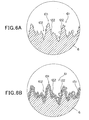
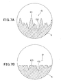
- Figs. 7 and 8 are diagrams showing the surface state of the valve lifter 6 according to a third embodiment, wherein Fig. 7A is an enlarged view showing the surface state before a polishing step (first step described later), Fig. 7B is an enlarged view showing the surface state after the polishing step, Fig. 8A is an enlarged view showing the surface state before the nitriding treatment (third step described later), and Fig. 8B is an enlarged view showing the surface state after the nitriding treatment.
- the third embodiment is the same as the first and second embodiments except for the surface treatment on the top face 61 of the valve lifter 6. Parts having the common constructions are represented by the same reference numerals, and the illustration and description thereof are omitted.
- the surface treatment of the third embodiment is conducted according to the following procedure.
- the top face 61 having the projecting portions 101 and the recess portions 102 shown in Fig. 7A is polished.
- the polishing is conducted without using the hard particles 122.
- a method using a general rotational grind stone is known as a polishing method.
- the top face 61 may be cleaned to remove material used for polishing.
- the top face 61 becomes a surface of high smoothness having a flat face 103.
- hard particles 122 are dispersed onto the top face 61 by a method of spraying or scattering the hard particles 122 onto the polished top face 61.
- the hard particles 122 adhere onto the whole top face 61 containing the projecting portions 101 and the recess portions 102 as shown in Fig. 8A .
- the density of the hard particles 122 when the hard particles 122 are dispersed complies with the density described with reference to the first embodiment described above. The same is applied to the particle diameter of the hard particles 122.
- the nitriding treatment of the third step is conducted, and the nitride layer 131 is formed on the top face 61 as shown in Fig. 8B .
- the nitriding layer 131 is formed in the direction from the surface layer of the top face 61 to the inside of the base material, and grows from the surface layer of the top face 61 to the outside so as to wrap the hard particles 122, thereby forming the nitride layer 131 containing the hard particles 122.
- the hard particles 122 are dispersed on the top face 61 and the nitriding treatment is conducted. Accordingly, when the top face 61 is polished, the top face 61 can be smoothed at higher level. That is, most of the hard particles 122 having higher hardness than the base material constituting the top face 61 have incisive shapes, and are excellent in cutting force. Furthermore, the smoothness is dependent on the particle diameter, and thus minute hard particles are preferably used to enhance the smoothness.
- the smoothness can be easily enhanced although the cutting force is lower. Furthermore, recesses (for example, the recess portions 104 shown in Fig. 4A ) caused by impingement of the hard particles 122 are not formed on the top face 61. Accordingly, according to the surface treatment method of the third embodiment, in addition to the same effect as described with reference to the first embodiment, the nitride layer 131 containing the hard particles 122 is formed under the state that the smoothness of the top face 61 is further enhanced, so that there is an advantage that enhancement of the abrasion resistance of the top face 61 can be implemented.
- the above embodiments are mere embodiments of the present invention, and the present invention is not limited to the above construction.
- the illustration and description are made in the case where alumina particles having incisive shapes are used as an example of the hard particles 122.
- the present invention is not limited to this style, and particles which are shaped not to have sharp corners (for example, spherical particles) may be used as the hard particles 122.
- the nitriding treatment is conducted under the state that only the hard particles 122 are dispersed on the top face 61.
- the present invention is not limited to this style.
- particles formed of another material such as metal material, synthetic resin, synthetic rubber or the like may be made to adhere to the top face 61.
- the surface treatment of the present invention is applied to the top face 61 of the valve lifter 6 which slides with the air intake cam 70 to open/close the air intake valve 3.
- the present invention is not limited to this style.
- the present invention may be applied to the peripheral surface of the air intake cam 70, and also applied to the sliding face between the exhaust cam 71 and the roller 81, the sliding face between the cam shaft 7 and the cylinder head 2 and any of various sliding faces in the internal combustion engines 100 with no limitation.
- the present invention is not limited to the internal combustion engine 100, and may be applied to any member without limitation insofar as the member has a mechanical sliding face.
Landscapes
- Engineering & Computer Science (AREA)
- Mechanical Engineering (AREA)
- Chemical & Material Sciences (AREA)
- General Engineering & Computer Science (AREA)
- Chemical Kinetics & Catalysis (AREA)
- Materials Engineering (AREA)
- Metallurgy (AREA)
- Organic Chemistry (AREA)
- Valve-Gear Or Valve Arrangements (AREA)
- Gears, Cams (AREA)
- Solid-Phase Diffusion Into Metallic Material Surfaces (AREA)
Applications Claiming Priority (2)
| Application Number | Priority Date | Filing Date | Title |
|---|---|---|---|
| JP2008022082 | 2008-01-31 | ||
| PCT/JP2009/000123 WO2009096143A1 (ja) | 2008-01-31 | 2009-01-15 | 摺動部材、及び、摺動部材の表面処理方法 |
Publications (3)
| Publication Number | Publication Date |
|---|---|
| EP2246533A1 true EP2246533A1 (de) | 2010-11-03 |
| EP2246533A4 EP2246533A4 (de) | 2012-03-14 |
| EP2246533B1 EP2246533B1 (de) | 2013-03-20 |
Family
ID=40912500
Family Applications (1)
| Application Number | Title | Priority Date | Filing Date |
|---|---|---|---|
| EP09705288A Not-in-force EP2246533B1 (de) | 2008-01-31 | 2009-01-15 | Gleitelement und verfahren zur behandlung der oberfläche des gleitelements |
Country Status (4)
| Country | Link |
|---|---|
| US (1) | US8505510B2 (de) |
| EP (1) | EP2246533B1 (de) |
| JP (1) | JP5086373B2 (de) |
| WO (1) | WO2009096143A1 (de) |
Cited By (3)
| Publication number | Priority date | Publication date | Assignee | Title |
|---|---|---|---|---|
| FR2983216A1 (fr) * | 2011-11-28 | 2013-05-31 | Peugeot Citroen Automobiles Sa | Ensemble d'au moins deux pieces mecaniques metalliques destinees a etre en contact glissant |
| WO2014161537A1 (de) * | 2013-04-05 | 2014-10-09 | Schaeffler Technologies Gmbh & Co. Kg | Stössel zur ventil- oder pumpenbetätigung und herstellungsverfahren für einen stössel zur ventil- oder pumpenbetätigung |
| EP2653671A4 (de) * | 2010-12-13 | 2016-04-06 | Kawasaki Heavy Ind Ltd | Steuernocken und ventiltriebvorrichtung für einen motor |
Families Citing this family (2)
| Publication number | Priority date | Publication date | Assignee | Title |
|---|---|---|---|---|
| JP2012219709A (ja) * | 2011-04-08 | 2012-11-12 | Hitachi Automotive Systems Ltd | 内燃機関のバルブリフタ及び該バルブリフタの製造方法 |
| JP6605322B2 (ja) * | 2015-12-22 | 2019-11-13 | オーエスジー株式会社 | 工具の表面改質方法 |
Family Cites Families (14)
| Publication number | Priority date | Publication date | Assignee | Title |
|---|---|---|---|---|
| JPS6421098A (en) * | 1987-07-16 | 1989-01-24 | Riken Kk | Sliding member |
| US4909198A (en) * | 1988-03-01 | 1990-03-20 | Toyota Jidosha Kabushiki Kaisha | Aluminum alloy valve lifter with sprayed coating and method of producing same |
| JPH05179421A (ja) * | 1991-12-26 | 1993-07-20 | Hitachi Constr Mach Co Ltd | Al系摺動部材およびその製造方法 |
| JPH06235096A (ja) * | 1993-02-09 | 1994-08-23 | Riken Corp | 摺動部材 |
| JPH06297254A (ja) * | 1993-02-19 | 1994-10-25 | Sumitomo Electric Ind Ltd | 摺動部材及びその製造方法 |
| JP3167227B2 (ja) | 1993-08-16 | 2001-05-21 | トヨタ自動車株式会社 | アジャスティングシム及びその製造方法 |
| KR100328108B1 (ko) * | 1996-10-15 | 2002-03-09 | 아사무라 타카싯 | 반도체 기판용 연마패드의 드레서, 그 제조방법 및 그것을 사용한 화학적 기계적 연마방법 |
| JP2001158689A (ja) * | 1999-12-01 | 2001-06-12 | Sumitomo Electric Ind Ltd | ダイヤモンド被覆摺動部品 |
| JP3794255B2 (ja) * | 2000-09-21 | 2006-07-05 | 日産自動車株式会社 | 摺動部品及びその製造方法 |
| JP4451994B2 (ja) | 2001-03-07 | 2010-04-14 | 株式会社オティックス | 動弁機構の摺動部材及びその表面処理方法 |
| DE10145599C1 (de) * | 2001-09-15 | 2003-06-18 | Gkn Loebro Gmbh | Bauteile aus Stahl und Verfahren zur Wärmebehandlung von Bauteilen aus Stahl |
| JP2004183075A (ja) | 2002-12-05 | 2004-07-02 | Toyo Kohan Co Ltd | 耐摩耗部材およびそれを用いた転動部材 |
| JP4137122B2 (ja) * | 2003-10-31 | 2008-08-20 | 日本ピストンリング株式会社 | カムシャフトの製造方法、カムシャフト及びこれに用いるカムロブ材 |
| JP2006214314A (ja) | 2005-02-02 | 2006-08-17 | Riken Corp | バルブリフター及びシムの製造方法 |
-
2009
- 2009-01-15 JP JP2009551415A patent/JP5086373B2/ja active Active
- 2009-01-15 US US12/863,345 patent/US8505510B2/en not_active Expired - Fee Related
- 2009-01-15 EP EP09705288A patent/EP2246533B1/de not_active Not-in-force
- 2009-01-15 WO PCT/JP2009/000123 patent/WO2009096143A1/ja not_active Ceased
Cited By (3)
| Publication number | Priority date | Publication date | Assignee | Title |
|---|---|---|---|---|
| EP2653671A4 (de) * | 2010-12-13 | 2016-04-06 | Kawasaki Heavy Ind Ltd | Steuernocken und ventiltriebvorrichtung für einen motor |
| FR2983216A1 (fr) * | 2011-11-28 | 2013-05-31 | Peugeot Citroen Automobiles Sa | Ensemble d'au moins deux pieces mecaniques metalliques destinees a etre en contact glissant |
| WO2014161537A1 (de) * | 2013-04-05 | 2014-10-09 | Schaeffler Technologies Gmbh & Co. Kg | Stössel zur ventil- oder pumpenbetätigung und herstellungsverfahren für einen stössel zur ventil- oder pumpenbetätigung |
Also Published As
| Publication number | Publication date |
|---|---|
| JPWO2009096143A1 (ja) | 2011-05-26 |
| EP2246533A4 (de) | 2012-03-14 |
| US20110114045A1 (en) | 2011-05-19 |
| WO2009096143A1 (ja) | 2009-08-06 |
| US8505510B2 (en) | 2013-08-13 |
| JP5086373B2 (ja) | 2012-11-28 |
| EP2246533B1 (de) | 2013-03-20 |
Similar Documents
| Publication | Publication Date | Title |
|---|---|---|
| EP2246533B1 (de) | Gleitelement und verfahren zur behandlung der oberfläche des gleitelements | |
| JP4269443B2 (ja) | 摺動部材の表面処理方法及び該方法を用いた摺動部材の表面平滑化方法 | |
| WO2001002712A1 (en) | Sliding member and piston for internal combustion engine | |
| Kim et al. | Tribological properties of twin wire arc spray coated aluminum cylinder liner | |
| JPH0821297A (ja) | 内燃機関の摺接部構造 | |
| JP4141473B2 (ja) | 窒化バルブリフタおよびその製造方法 | |
| KR100253920B1 (ko) | 밸브가이드 및 그 제조방법 | |
| CA2496667A1 (en) | Wear-resistant slide member and slide device using the same | |
| CN1734064A (zh) | 气门挺柱及其成形和处理方法 | |
| JP2006009080A (ja) | 摺動部材及び該摺動部材の表面処理方法 | |
| Gangopadhyay et al. | The effect of novel surface textures on tappet shims on valvetrain friction and wear | |
| WO2010044216A1 (ja) | 摺動部材およびその製造方法 | |
| EP2146087B1 (de) | Kraftstoffeinspritzvorrichtung für Dieselmotor, Verfahren zu deren Herstellung und Ventileinheit | |
| US6220214B1 (en) | Cylinder liner formed with cross-hatching grooves | |
| JPH10130891A (ja) | 複合Crめっき皮膜およびこれを有する摺動部材 | |
| JP3362831B2 (ja) | ピストンリング | |
| JP2004340128A (ja) | 内燃機関の動弁装置 | |
| CN114555930A (zh) | 气缸与活塞环的组合 | |
| JP5231980B2 (ja) | ロッカーアームとその研磨仕上げ方法 | |
| JPH08233070A (ja) | カムフォロワ用ローラ | |
| JP2001349411A (ja) | カム駒、およびカムシャフトの製造方法 | |
| do Vale et al. | Evaluation of friction coefficient of lamellar and compacted graphite irons in lubricated ring-on-cylinder system | |
| JPH08226311A (ja) | セラミックス製アジャスティングシム | |
| JP2016102452A (ja) | バルブステムの判定方法 | |
| Guo et al. | Study on fretting wear properties of high speed diesel engine roller tappet material Cr12W steel |
Legal Events
| Date | Code | Title | Description |
|---|---|---|---|
| PUAI | Public reference made under article 153(3) epc to a published international application that has entered the european phase |
Free format text: ORIGINAL CODE: 0009012 |
|
| 17P | Request for examination filed |
Effective date: 20100729 |
|
| AK | Designated contracting states |
Kind code of ref document: A1 Designated state(s): AT BE BG CH CY CZ DE DK EE ES FI FR GB GR HR HU IE IS IT LI LT LU LV MC MK MT NL NO PL PT RO SE SI SK TR |
|
| AX | Request for extension of the european patent |
Extension state: AL BA RS |
|
| DAX | Request for extension of the european patent (deleted) | ||
| A4 | Supplementary search report drawn up and despatched |
Effective date: 20120209 |
|
| RIC1 | Information provided on ipc code assigned before grant |
Ipc: F16H 53/02 20060101ALI20120203BHEP Ipc: C23C 8/02 20060101ALI20120203BHEP Ipc: F01L 1/053 20060101ALI20120203BHEP Ipc: F01L 1/18 20060101ALI20120203BHEP Ipc: F16H 53/06 20060101ALI20120203BHEP Ipc: C23C 8/26 20060101ALI20120203BHEP Ipc: F01L 1/14 20060101AFI20120203BHEP Ipc: C23C 8/24 20060101ALI20120203BHEP |
|
| GRAP | Despatch of communication of intention to grant a patent |
Free format text: ORIGINAL CODE: EPIDOSNIGR1 |
|
| GRAS | Grant fee paid |
Free format text: ORIGINAL CODE: EPIDOSNIGR3 |
|
| GRAA | (expected) grant |
Free format text: ORIGINAL CODE: 0009210 |
|
| AK | Designated contracting states |
Kind code of ref document: B1 Designated state(s): AT BE BG CH CY CZ DE DK EE ES FI FR GB GR HR HU IE IS IT LI LT LU LV MC MK MT NL NO PL PT RO SE SI SK TR |
|
| REG | Reference to a national code |
Ref country code: GB Ref legal event code: FG4D |
|
| REG | Reference to a national code |
Ref country code: CH Ref legal event code: EP |
|
| REG | Reference to a national code |
Ref country code: IE Ref legal event code: FG4D |
|
| REG | Reference to a national code |
Ref country code: AT Ref legal event code: REF Ref document number: 602218 Country of ref document: AT Kind code of ref document: T Effective date: 20130415 |
|
| REG | Reference to a national code |
Ref country code: DE Ref legal event code: R096 Ref document number: 602009014162 Country of ref document: DE Effective date: 20130516 |
|
| PG25 | Lapsed in a contracting state [announced via postgrant information from national office to epo] |
Ref country code: BG Free format text: LAPSE BECAUSE OF FAILURE TO SUBMIT A TRANSLATION OF THE DESCRIPTION OR TO PAY THE FEE WITHIN THE PRESCRIBED TIME-LIMIT Effective date: 20130620 Ref country code: ES Free format text: LAPSE BECAUSE OF FAILURE TO SUBMIT A TRANSLATION OF THE DESCRIPTION OR TO PAY THE FEE WITHIN THE PRESCRIBED TIME-LIMIT Effective date: 20130701 Ref country code: LT Free format text: LAPSE BECAUSE OF FAILURE TO SUBMIT A TRANSLATION OF THE DESCRIPTION OR TO PAY THE FEE WITHIN THE PRESCRIBED TIME-LIMIT Effective date: 20130320 Ref country code: SE Free format text: LAPSE BECAUSE OF FAILURE TO SUBMIT A TRANSLATION OF THE DESCRIPTION OR TO PAY THE FEE WITHIN THE PRESCRIBED TIME-LIMIT Effective date: 20130320 Ref country code: NO Free format text: LAPSE BECAUSE OF FAILURE TO SUBMIT A TRANSLATION OF THE DESCRIPTION OR TO PAY THE FEE WITHIN THE PRESCRIBED TIME-LIMIT Effective date: 20130620 |
|
| REG | Reference to a national code |
Ref country code: AT Ref legal event code: MK05 Ref document number: 602218 Country of ref document: AT Kind code of ref document: T Effective date: 20130320 |
|
| REG | Reference to a national code |
Ref country code: LT Ref legal event code: MG4D |
|
| PG25 | Lapsed in a contracting state [announced via postgrant information from national office to epo] |
Ref country code: GR Free format text: LAPSE BECAUSE OF FAILURE TO SUBMIT A TRANSLATION OF THE DESCRIPTION OR TO PAY THE FEE WITHIN THE PRESCRIBED TIME-LIMIT Effective date: 20130621 Ref country code: FI Free format text: LAPSE BECAUSE OF FAILURE TO SUBMIT A TRANSLATION OF THE DESCRIPTION OR TO PAY THE FEE WITHIN THE PRESCRIBED TIME-LIMIT Effective date: 20130320 Ref country code: SI Free format text: LAPSE BECAUSE OF FAILURE TO SUBMIT A TRANSLATION OF THE DESCRIPTION OR TO PAY THE FEE WITHIN THE PRESCRIBED TIME-LIMIT Effective date: 20130320 Ref country code: LV Free format text: LAPSE BECAUSE OF FAILURE TO SUBMIT A TRANSLATION OF THE DESCRIPTION OR TO PAY THE FEE WITHIN THE PRESCRIBED TIME-LIMIT Effective date: 20130320 |
|
| REG | Reference to a national code |
Ref country code: NL Ref legal event code: VDEP Effective date: 20130320 |
|
| PG25 | Lapsed in a contracting state [announced via postgrant information from national office to epo] |
Ref country code: HR Free format text: LAPSE BECAUSE OF FAILURE TO SUBMIT A TRANSLATION OF THE DESCRIPTION OR TO PAY THE FEE WITHIN THE PRESCRIBED TIME-LIMIT Effective date: 20130320 Ref country code: BE Free format text: LAPSE BECAUSE OF FAILURE TO SUBMIT A TRANSLATION OF THE DESCRIPTION OR TO PAY THE FEE WITHIN THE PRESCRIBED TIME-LIMIT Effective date: 20130320 |
|
| PG25 | Lapsed in a contracting state [announced via postgrant information from national office to epo] |
Ref country code: EE Free format text: LAPSE BECAUSE OF FAILURE TO SUBMIT A TRANSLATION OF THE DESCRIPTION OR TO PAY THE FEE WITHIN THE PRESCRIBED TIME-LIMIT Effective date: 20130320 Ref country code: IS Free format text: LAPSE BECAUSE OF FAILURE TO SUBMIT A TRANSLATION OF THE DESCRIPTION OR TO PAY THE FEE WITHIN THE PRESCRIBED TIME-LIMIT Effective date: 20130720 Ref country code: CZ Free format text: LAPSE BECAUSE OF FAILURE TO SUBMIT A TRANSLATION OF THE DESCRIPTION OR TO PAY THE FEE WITHIN THE PRESCRIBED TIME-LIMIT Effective date: 20130320 Ref country code: AT Free format text: LAPSE BECAUSE OF FAILURE TO SUBMIT A TRANSLATION OF THE DESCRIPTION OR TO PAY THE FEE WITHIN THE PRESCRIBED TIME-LIMIT Effective date: 20130320 Ref country code: NL Free format text: LAPSE BECAUSE OF FAILURE TO SUBMIT A TRANSLATION OF THE DESCRIPTION OR TO PAY THE FEE WITHIN THE PRESCRIBED TIME-LIMIT Effective date: 20130320 Ref country code: RO Free format text: LAPSE BECAUSE OF FAILURE TO SUBMIT A TRANSLATION OF THE DESCRIPTION OR TO PAY THE FEE WITHIN THE PRESCRIBED TIME-LIMIT Effective date: 20130320 Ref country code: PT Free format text: LAPSE BECAUSE OF FAILURE TO SUBMIT A TRANSLATION OF THE DESCRIPTION OR TO PAY THE FEE WITHIN THE PRESCRIBED TIME-LIMIT Effective date: 20130722 Ref country code: SK Free format text: LAPSE BECAUSE OF FAILURE TO SUBMIT A TRANSLATION OF THE DESCRIPTION OR TO PAY THE FEE WITHIN THE PRESCRIBED TIME-LIMIT Effective date: 20130320 |
|
| PG25 | Lapsed in a contracting state [announced via postgrant information from national office to epo] |
Ref country code: PL Free format text: LAPSE BECAUSE OF FAILURE TO SUBMIT A TRANSLATION OF THE DESCRIPTION OR TO PAY THE FEE WITHIN THE PRESCRIBED TIME-LIMIT Effective date: 20130320 Ref country code: CY Free format text: LAPSE BECAUSE OF FAILURE TO SUBMIT A TRANSLATION OF THE DESCRIPTION OR TO PAY THE FEE WITHIN THE PRESCRIBED TIME-LIMIT Effective date: 20130320 |
|
| PLBE | No opposition filed within time limit |
Free format text: ORIGINAL CODE: 0009261 |
|
| STAA | Information on the status of an ep patent application or granted ep patent |
Free format text: STATUS: NO OPPOSITION FILED WITHIN TIME LIMIT |
|
| PG25 | Lapsed in a contracting state [announced via postgrant information from national office to epo] |
Ref country code: DK Free format text: LAPSE BECAUSE OF FAILURE TO SUBMIT A TRANSLATION OF THE DESCRIPTION OR TO PAY THE FEE WITHIN THE PRESCRIBED TIME-LIMIT Effective date: 20130320 |
|
| 26N | No opposition filed |
Effective date: 20140102 |
|
| REG | Reference to a national code |
Ref country code: DE Ref legal event code: R097 Ref document number: 602009014162 Country of ref document: DE Effective date: 20140102 |
|
| PG25 | Lapsed in a contracting state [announced via postgrant information from national office to epo] |
Ref country code: LU Free format text: LAPSE BECAUSE OF FAILURE TO SUBMIT A TRANSLATION OF THE DESCRIPTION OR TO PAY THE FEE WITHIN THE PRESCRIBED TIME-LIMIT Effective date: 20140115 Ref country code: MC Free format text: LAPSE BECAUSE OF FAILURE TO SUBMIT A TRANSLATION OF THE DESCRIPTION OR TO PAY THE FEE WITHIN THE PRESCRIBED TIME-LIMIT Effective date: 20130320 |
|
| REG | Reference to a national code |
Ref country code: CH Ref legal event code: PL |
|
| PG25 | Lapsed in a contracting state [announced via postgrant information from national office to epo] |
Ref country code: LI Free format text: LAPSE BECAUSE OF NON-PAYMENT OF DUE FEES Effective date: 20140131 Ref country code: CH Free format text: LAPSE BECAUSE OF NON-PAYMENT OF DUE FEES Effective date: 20140131 |
|
| REG | Reference to a national code |
Ref country code: FR Ref legal event code: ST Effective date: 20140930 |
|
| REG | Reference to a national code |
Ref country code: IE Ref legal event code: MM4A |
|
| PG25 | Lapsed in a contracting state [announced via postgrant information from national office to epo] |
Ref country code: FR Free format text: LAPSE BECAUSE OF NON-PAYMENT OF DUE FEES Effective date: 20140131 |
|
| PG25 | Lapsed in a contracting state [announced via postgrant information from national office to epo] |
Ref country code: IE Free format text: LAPSE BECAUSE OF NON-PAYMENT OF DUE FEES Effective date: 20140115 |
|
| PG25 | Lapsed in a contracting state [announced via postgrant information from national office to epo] |
Ref country code: MT Free format text: LAPSE BECAUSE OF FAILURE TO SUBMIT A TRANSLATION OF THE DESCRIPTION OR TO PAY THE FEE WITHIN THE PRESCRIBED TIME-LIMIT Effective date: 20130320 |
|
| PG25 | Lapsed in a contracting state [announced via postgrant information from national office to epo] |
Ref country code: TR Free format text: LAPSE BECAUSE OF FAILURE TO SUBMIT A TRANSLATION OF THE DESCRIPTION OR TO PAY THE FEE WITHIN THE PRESCRIBED TIME-LIMIT Effective date: 20130320 Ref country code: HU Free format text: LAPSE BECAUSE OF FAILURE TO SUBMIT A TRANSLATION OF THE DESCRIPTION OR TO PAY THE FEE WITHIN THE PRESCRIBED TIME-LIMIT; INVALID AB INITIO Effective date: 20090115 |
|
| PGFP | Annual fee paid to national office [announced via postgrant information from national office to epo] |
Ref country code: GB Payment date: 20180117 Year of fee payment: 10 |
|
| PG25 | Lapsed in a contracting state [announced via postgrant information from national office to epo] |
Ref country code: MK Free format text: LAPSE BECAUSE OF FAILURE TO SUBMIT A TRANSLATION OF THE DESCRIPTION OR TO PAY THE FEE WITHIN THE PRESCRIBED TIME-LIMIT Effective date: 20130320 |
|
| PGFP | Annual fee paid to national office [announced via postgrant information from national office to epo] |
Ref country code: DE Payment date: 20190128 Year of fee payment: 11 Ref country code: IT Payment date: 20190121 Year of fee payment: 11 |
|
| GBPC | Gb: european patent ceased through non-payment of renewal fee |
Effective date: 20190115 |
|
| PG25 | Lapsed in a contracting state [announced via postgrant information from national office to epo] |
Ref country code: GB Free format text: LAPSE BECAUSE OF NON-PAYMENT OF DUE FEES Effective date: 20190115 |
|
| REG | Reference to a national code |
Ref country code: DE Ref legal event code: R119 Ref document number: 602009014162 Country of ref document: DE |
|
| PG25 | Lapsed in a contracting state [announced via postgrant information from national office to epo] |
Ref country code: DE Free format text: LAPSE BECAUSE OF NON-PAYMENT OF DUE FEES Effective date: 20200801 |
|
| PG25 | Lapsed in a contracting state [announced via postgrant information from national office to epo] |
Ref country code: IT Free format text: LAPSE BECAUSE OF NON-PAYMENT OF DUE FEES Effective date: 20200115 |