EP2246540B1 - Stromerzeugungssystem für Fahrzeug mittels Abgas - Google Patents
Stromerzeugungssystem für Fahrzeug mittels Abgas Download PDFInfo
- Publication number
- EP2246540B1 EP2246540B1 EP10275043A EP10275043A EP2246540B1 EP 2246540 B1 EP2246540 B1 EP 2246540B1 EP 10275043 A EP10275043 A EP 10275043A EP 10275043 A EP10275043 A EP 10275043A EP 2246540 B1 EP2246540 B1 EP 2246540B1
- Authority
- EP
- European Patent Office
- Prior art keywords
- casing
- exhaust gas
- inlet hole
- turbine
- wing
- Prior art date
- Legal status (The legal status is an assumption and is not a legal conclusion. Google has not performed a legal analysis and makes no representation as to the accuracy of the status listed.)
- Not-in-force
Links
Images

Classifications
-
- F—MECHANICAL ENGINEERING; LIGHTING; HEATING; WEAPONS; BLASTING
- F01—MACHINES OR ENGINES IN GENERAL; ENGINE PLANTS IN GENERAL; STEAM ENGINES
- F01N—GAS-FLOW SILENCERS OR EXHAUST APPARATUS FOR MACHINES OR ENGINES IN GENERAL; GAS-FLOW SILENCERS OR EXHAUST APPARATUS FOR INTERNAL-COMBUSTION ENGINES
- F01N5/00—Exhaust or silencing apparatus combined or associated with devices profiting by exhaust energy
- F01N5/04—Exhaust or silencing apparatus combined or associated with devices profiting by exhaust energy the devices using kinetic energy
-
- F—MECHANICAL ENGINEERING; LIGHTING; HEATING; WEAPONS; BLASTING
- F01—MACHINES OR ENGINES IN GENERAL; ENGINE PLANTS IN GENERAL; STEAM ENGINES
- F01D—NON-POSITIVE DISPLACEMENT MACHINES OR ENGINES, e.g. STEAM TURBINES
- F01D1/00—Non-positive-displacement machines or engines, e.g. steam turbines
- F01D1/02—Non-positive-displacement machines or engines, e.g. steam turbines with stationary working-fluid guiding means and bladed or like rotor, e.g. multi-bladed impulse steam turbines
- F01D1/026—Impact turbines with buckets, i.e. impulse turbines, e.g. Pelton turbines
-
- F—MECHANICAL ENGINEERING; LIGHTING; HEATING; WEAPONS; BLASTING
- F01—MACHINES OR ENGINES IN GENERAL; ENGINE PLANTS IN GENERAL; STEAM ENGINES
- F01N—GAS-FLOW SILENCERS OR EXHAUST APPARATUS FOR MACHINES OR ENGINES IN GENERAL; GAS-FLOW SILENCERS OR EXHAUST APPARATUS FOR INTERNAL-COMBUSTION ENGINES
- F01N5/00—Exhaust or silencing apparatus combined or associated with devices profiting by exhaust energy
-
- F—MECHANICAL ENGINEERING; LIGHTING; HEATING; WEAPONS; BLASTING
- F02—COMBUSTION ENGINES; HOT-GAS OR COMBUSTION-PRODUCT ENGINE PLANTS
- F02M—SUPPLYING COMBUSTION ENGINES IN GENERAL WITH COMBUSTIBLE MIXTURES OR CONSTITUENTS THEREOF
- F02M21/00—Apparatus for supplying engines with non-liquid fuels, e.g. gaseous fuels stored in liquid form
- F02M21/02—Apparatus for supplying engines with non-liquid fuels, e.g. gaseous fuels stored in liquid form for gaseous fuels
- F02M21/0203—Apparatus for supplying engines with non-liquid fuels, e.g. gaseous fuels stored in liquid form for gaseous fuels characterised by the type of gaseous fuel
- F02M21/0206—Non-hydrocarbon fuels, e.g. hydrogen, ammonia or carbon monoxide
-
- F—MECHANICAL ENGINEERING; LIGHTING; HEATING; WEAPONS; BLASTING
- F02—COMBUSTION ENGINES; HOT-GAS OR COMBUSTION-PRODUCT ENGINE PLANTS
- F02M—SUPPLYING COMBUSTION ENGINES IN GENERAL WITH COMBUSTIBLE MIXTURES OR CONSTITUENTS THEREOF
- F02M21/00—Apparatus for supplying engines with non-liquid fuels, e.g. gaseous fuels stored in liquid form
- F02M21/02—Apparatus for supplying engines with non-liquid fuels, e.g. gaseous fuels stored in liquid form for gaseous fuels
- F02M21/0218—Details on the gaseous fuel supply system, e.g. tanks, valves, pipes, pumps, rails, injectors or mixers
- F02M21/0227—Means to treat or clean gaseous fuels or fuel systems, e.g. removal of tar, cracking, reforming or enriching
-
- F—MECHANICAL ENGINEERING; LIGHTING; HEATING; WEAPONS; BLASTING
- F02—COMBUSTION ENGINES; HOT-GAS OR COMBUSTION-PRODUCT ENGINE PLANTS
- F02B—INTERNAL-COMBUSTION PISTON ENGINES; COMBUSTION ENGINES IN GENERAL
- F02B43/00—Engines characterised by operating on gaseous fuels; Plants including such engines
- F02B43/10—Engines or plants characterised by use of other specific gases, e.g. acetylene, oxyhydrogen
- F02B2043/106—Hydrogen obtained by electrolysis
-
- F—MECHANICAL ENGINEERING; LIGHTING; HEATING; WEAPONS; BLASTING
- F02—COMBUSTION ENGINES; HOT-GAS OR COMBUSTION-PRODUCT ENGINE PLANTS
- F02M—SUPPLYING COMBUSTION ENGINES IN GENERAL WITH COMBUSTIBLE MIXTURES OR CONSTITUENTS THEREOF
- F02M25/00—Engine-pertinent apparatus for adding non-fuel substances or small quantities of secondary fuel to combustion-air, main fuel or fuel-air mixture
- F02M25/10—Engine-pertinent apparatus for adding non-fuel substances or small quantities of secondary fuel to combustion-air, main fuel or fuel-air mixture adding acetylene, non-waterborne hydrogen, non-airborne oxygen, or ozone
- F02M25/12—Engine-pertinent apparatus for adding non-fuel substances or small quantities of secondary fuel to combustion-air, main fuel or fuel-air mixture adding acetylene, non-waterborne hydrogen, non-airborne oxygen, or ozone the apparatus having means for generating such gases
-
- F—MECHANICAL ENGINEERING; LIGHTING; HEATING; WEAPONS; BLASTING
- F05—INDEXING SCHEMES RELATING TO ENGINES OR PUMPS IN VARIOUS SUBCLASSES OF CLASSES F01-F04
- F05D—INDEXING SCHEME FOR ASPECTS RELATING TO NON-POSITIVE-DISPLACEMENT MACHINES OR ENGINES, GAS-TURBINES OR JET-PROPULSION PLANTS
- F05D2220/00—Application
- F05D2220/70—Application in combination with
- F05D2220/76—Application in combination with an electrical generator
-
- Y—GENERAL TAGGING OF NEW TECHNOLOGICAL DEVELOPMENTS; GENERAL TAGGING OF CROSS-SECTIONAL TECHNOLOGIES SPANNING OVER SEVERAL SECTIONS OF THE IPC; TECHNICAL SUBJECTS COVERED BY FORMER USPC CROSS-REFERENCE ART COLLECTIONS [XRACs] AND DIGESTS
- Y02—TECHNOLOGIES OR APPLICATIONS FOR MITIGATION OR ADAPTATION AGAINST CLIMATE CHANGE
- Y02T—CLIMATE CHANGE MITIGATION TECHNOLOGIES RELATED TO TRANSPORTATION
- Y02T10/00—Road transport of goods or passengers
- Y02T10/10—Internal combustion engine [ICE] based vehicles
- Y02T10/12—Improving ICE efficiencies
-
- Y—GENERAL TAGGING OF NEW TECHNOLOGICAL DEVELOPMENTS; GENERAL TAGGING OF CROSS-SECTIONAL TECHNOLOGIES SPANNING OVER SEVERAL SECTIONS OF THE IPC; TECHNICAL SUBJECTS COVERED BY FORMER USPC CROSS-REFERENCE ART COLLECTIONS [XRACs] AND DIGESTS
- Y02—TECHNOLOGIES OR APPLICATIONS FOR MITIGATION OR ADAPTATION AGAINST CLIMATE CHANGE
- Y02T—CLIMATE CHANGE MITIGATION TECHNOLOGIES RELATED TO TRANSPORTATION
- Y02T10/00—Road transport of goods or passengers
- Y02T10/10—Internal combustion engine [ICE] based vehicles
- Y02T10/30—Use of alternative fuels, e.g. biofuels
-
- Y—GENERAL TAGGING OF NEW TECHNOLOGICAL DEVELOPMENTS; GENERAL TAGGING OF CROSS-SECTIONAL TECHNOLOGIES SPANNING OVER SEVERAL SECTIONS OF THE IPC; TECHNICAL SUBJECTS COVERED BY FORMER USPC CROSS-REFERENCE ART COLLECTIONS [XRACs] AND DIGESTS
- Y02—TECHNOLOGIES OR APPLICATIONS FOR MITIGATION OR ADAPTATION AGAINST CLIMATE CHANGE
- Y02T—CLIMATE CHANGE MITIGATION TECHNOLOGIES RELATED TO TRANSPORTATION
- Y02T90/00—Enabling technologies or technologies with a potential or indirect contribution to GHG emissions mitigation
- Y02T90/40—Application of hydrogen technology to transportation, e.g. using fuel cells
Definitions
- the present invention relates to a vehicle power generation system using exhaust gas, and in particular to a vehicle power generation system using exhaust gas which generates electric power used for electrolysis as the system is used in a vehicle which uses a mixed gas of hydrogen and oxygen.
- a hydrogen-oxygen mixed gas generation apparatus is constituted to generate hydrogen and oxygen which are obtained as water is electrolysis-treated.
- the above apparatus generates a mixed gas of hydrogen and oxygen which is a non-pollution energy source by supplying water mixed with a small amount of electrolyte into an electrolysis tank equipped with a positive (+) electrode and a negative (-) electrode and applying a DC voltage thereto.
- the hydrogen and oxygen are produced at a molecular ration of 2:1, and hydrogen is produced in a form of bubble from the surface of the electrode (-), and oxygen is produced in a form of bubble from the surface of the electrode (+).
- the produced hydrogen and oxygen are mixed and become a mixed gas which is combustible. In casing of burning, any pollutants are not produced, so the hydrogen and oxygen gases are considered as an environment friendly energy source.
- the applicant of the present invention has tried to apply such hydrogen and oxygen mixed gas generation apparatus to a vehicle for thereby generating hydrogen and oxygen mixed gas and has researched to use the same as a fuel for driving an engine.
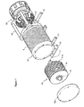
- a vehicle power generation system using exhaust gas which comprises a casing 10 which is installed at a vehicle chassis and is formed of an inlet hole 11 for inputting an exhaust gas and an outlet hole 12 for discharging an exhaust gas; a turbine 20 which is rotatably installed in the interior of the casing 10 and rotates by means of a pressure of the exhaust gas inputted into the inlet hole 11; a power generator 30 which has a rotatary shaft 31 axially engaged to a shaft part 21 of the turbine 20 passing through a front side of the casing 10; and a fixing bracket 40 for fixing the power generator 30 to the casing 10, wherein said inlet hole 11 is obliquely formed at a side portion of a front side of the casing 10, and said turbine 20 includes a shaft part 21 rotatably engaged to a bearing installed in the front and rear sides of the casing 10 and a wing assembly 22 rotated by a pressure of the exhaust gas inputted into the inlet hole 11, and said wing assembly 22 includes a pluralit
- the vehicle electric power generation system using an exhaust system of the present invention it is possible to generate electric power using exhaust gas without using an additional energy input since a turbine is rotated by means of an exhaust gas discharged from an engine, and the electric power is generated as the turbine drives the electric power generator.
- the turbine is formed of a plurality of wing disks equipped with latch wings being opposite to a plurality of inlet holes, so the turbine can be efficiently rotated by means of the exhaust gas, so that the electric power generator can be effectively driven for thereby generating a lot of electric power energy.
- Figure 1 is a perspective view of a vehicle power generation system using exhaust gas according to the present invention
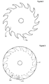
- Figure 2 is a front view of a wing disk belonging to a turbine of Figure 1
- Figure 3 is a front view of a partition disk belonging to a turbine of Figure 1
- Figure 4 is a view for explaining an inlet hole and a wing disk obliquely formed at a side portion of a casing in Figure 1
- Figure 5 is a side view of a turbine of Figure 1 .
- the vehicle power generation system using exhausting gas is installed a chassis of a vehicle, which includes a casing 10 which is installed at a vehicle chassis and is formed of an inlet hole 11 for inputting an exhaust gas and an outlet hole 12 for discharging an exhaust gas; a turbine 20 which is rotatably installed in the interior of the casing 10 and rotates by means of a pressure of the exhaust gas inputted into the inlet hole 11; a power generator 30 which has a rotary shaft 31 axially engaged to a shaft part 21 of the turbine 20 passing through a front side of the casing 10; and a fixing bracket 40 for fixing the power generator 30 to the casing 10.
- the casing 10 is formed in a cylindrical shape which is fixed to a fixing part of a chassis of a vehicle. As shown in Figures 1 and 4 , an inlet hole 11 is obliquely formed in a side portion of a front side of the casing 10 for inputting exhaust gas, and an outlet hole 12 is formed in a rear side of the casing 10 for discharging exhaust gas which has been used for rotating the turbine 20. Since the inlet hole 11 is obliquely formed, so the exhaust gas inputted into the inlet hole 11 can effectively rotate the turbine 20. At this time, the inlet hole 11 is connected with a muffler which finally discharges exhaust gas, and the outlet hole 12 is connected with an additional pipe.
- the inlet hole 11 might be connected with an exhaust manifold which exhausts exhaust from engine, and the outlet hole 12 may be connected with muffler.
- a bracket 13 is formed in the casing 10 and is engaged by means of a bolt and a nut to be fixed to a chassis of a vehicle.
- a plurality of radiation fins 15 are formed in an outer surface of the casing 10 for radiating heat which is generated by means of a high speed rotation of a turbine 20.
- the radiation fins 15 can be integrally formed when forming the casing 10 in a cylindrical shape or can be separately formed and engaged to the casing 10.
- the turbine 20 includes a shaft part 21 rotatably engaged to a bearing(not shown) installed in the front and rear sides of the casing 10, and a wing assembly 22 which is engaged to the shaft part 21 and rotates by means of a pressure of the exhaust gas inputted into the inlet hole 11.
- the wing assembly 22 may be formed in various forms, and in the embodiment of the present invention, the wing assembly 22 includes a plurality of wing disks 23 with a plurality of latch wings 23a being opposite to the direction of the inlet hole 11, and a partition disk 24 which partitions the wing disk 23 and other wing disk 23'.
- the front side of the latch 23a formed in the wing disk 23 is formed in a latch shape toward the inlet hole 11 for an easier rotation by means of an exhaust gas inputted into the inlet hole 11, and the rear side of the same is obliquely formed.
- a plurality of holes are formed in the partition disk 24 for discharging exhaust gas, and two holes 24a and 24b are preferably formed for easier description of the present invention. It is preferred that the holes 24a and 24b are obliquely formed when the thickness of the partition disk 24 is thick, and the inclination direction is toward the rotation direction of the turbine.
- the wing assembly is constituted in a structure that a plurality of wing disks 23 and a plurality of partition disks 24 are stacked in the shaft part 21.
- the wing assembly 22 is partitioned by means of the partition disk 24' of the front side in which four wing disks 23 are stacked in the direction of the inlet hole 11, and two wing disks 23 are stacked in the side of the outlet hole 12 and are partitioned by the partition disk 24" of the rear side, and a plurality of partition disks partition a plurality of wing disks stacked between the partition disk 24' of the front side and the partition disk 24" of the rear side partition.
- the latch wings 23a are arranged in spiral shape, and the holes 24a and 24b formed in the partition disks 24, 24' and 24" partitioning the wing disks are arranged in spiral shapes between the latch wings 23a.
- the exhaust gas inputted into the inlet hole 11 pushes and rotates the latch wings 23a disposed as being opposite and in spiral shapes, and the exhaust gas is discharged through the outlet hole 12 through the holes 24a and 24b and the latch wing 23a formed in the partition disk 24 arranged in spiral shape.
- the exhaust gas pushes the latch wings 23a disposed in a spiral shape and passes through the other latch wings and the spiral holes 24a and 24b of the partition disk and pass through the outlet hole 12 for thereby effectively rotating the turbine 20.
- the rotating turbine 20 rotates the rotor of the power generator 20 for thereby producing a lot of electric power.
- the fixing bracket 40 integrally fixes the power generator 30 to the casing 10.
Landscapes
- Engineering & Computer Science (AREA)
- Chemical & Material Sciences (AREA)
- Mechanical Engineering (AREA)
- General Engineering & Computer Science (AREA)
- Combustion & Propulsion (AREA)
- Chemical Kinetics & Catalysis (AREA)
- General Chemical & Material Sciences (AREA)
- Oil, Petroleum & Natural Gas (AREA)
- Engine Equipment That Uses Special Cycles (AREA)
- Exhaust Silencers (AREA)
- Cooling, Air Intake And Gas Exhaust, And Fuel Tank Arrangements In Propulsion Units (AREA)
- Supercharger (AREA)
Claims (2)
- Fahrzeug-Stromerzeugungssystem unter Verwendung von Auspuffgas, wobei das System Folgendes umfasst:ein Gehäuse (10), das an einem Fahrzeugchassis installiert und mit einer Einlassöffnung (11) zum Zuführen eines Auspuffgases und einer Auslassöffnung (12) zum Ausstoßen eines Auspuffgases ausgebildet ist;eine Turbine (20), die drehbar im Inneren des Gehäuses (10) installiert ist und sich mittels eines Drucks des in die Einlassöffnung (11) zugeführten Auspuffgases dreht;einen Stromerzeuger (30) der eine Radialwelle (31) aufweist, die axial mit einem Wellenteil (21) der Turbine (20) im Eingriff steht, das durch eine Vorderseite des Gehäuses (10) hindurch geht; undeine Befestigungshalterung (40) zum Befestigen des Stromerzeugers (30) an dem Gehäuse (10),wobei die Einlassöffnung (11) schräg an einem Seitenabschnitt einer Vorderseite des Gehäuses (10) ausgebildet ist und die Turbine (20) ein Wellenteil (21), das drehbar mit einem Lager im Eingriff steht, das in der Vorderseite und der Rückseite des Gehäuses (10) installiert ist, und eine Flügeleinheit (22) umfasst, die von einem Druck des in die Einlassöffnung (11) zugeführten Auspuffgases gedreht wird, und wobei die Flügeleinheit (22) mehrere Flügelscheiben (23) mit mehreren Sperrflügeln (23a) umfasst, die der Einlassöffnung (11) gegenüberliegen, und wobei die Flügeleinheit (22) durch eine Unterteilscheibe (24') einer Vorderseite unterteilt wird, nachdem die Flügelscheiben (23) in der Richtung der Einlassöffnung (11) gestapelt wurden, und sie an der Unterteilscheibe (24'') der Rückseite unterteilt wird, und wobei mehrere Unterteilscheiben mehrere Flügel unterteilen, die zwischen der Unterteilscheibe (24') der Vorderseite und der Unterteilscheibe (24") der Rückseite gestapelt sind, und wobei die Sperrflügel (23a) in den gestapelten Flügelscheiben (13) in einer Spiralform angeordnet sind und Öffnungen (24a und 24b), die in den Unterteilscheiben (24, 24' und 24 ") ausgebildet sind, zwischen den Flügelscheiben (23a) in Spiralformen positioniert sind.
- System nach Anspruch 1, das weiterhin mehrere Abstrahlrippen (15), die auf einer Außenfläche des Gehäuses (10) ausgebildet sind, zum externen Abstrahlen der mittels einer Hochgeschwindigkeitsdrehung der Turbine (20) erzeugten Wärme umfasst.
Applications Claiming Priority (1)
| Application Number | Priority Date | Filing Date | Title |
|---|---|---|---|
| KR1020090034530A KR100934174B1 (ko) | 2009-04-21 | 2009-04-21 | 배기가스를 이용한 자동차 발전시스템 |
Publications (2)
| Publication Number | Publication Date |
|---|---|
| EP2246540A1 EP2246540A1 (de) | 2010-11-03 |
| EP2246540B1 true EP2246540B1 (de) | 2011-12-21 |
Family
ID=41684794
Family Applications (1)
| Application Number | Title | Priority Date | Filing Date |
|---|---|---|---|
| EP10275043A Not-in-force EP2246540B1 (de) | 2009-04-21 | 2010-04-16 | Stromerzeugungssystem für Fahrzeug mittels Abgas |
Country Status (8)
| Country | Link |
|---|---|
| US (1) | US20110072813A1 (de) |
| EP (1) | EP2246540B1 (de) |
| JP (1) | JP2010255632A (de) |
| KR (1) | KR100934174B1 (de) |
| AT (1) | ATE538291T1 (de) |
| AU (1) | AU2010201555A1 (de) |
| BR (1) | BRPI1001198A2 (de) |
| TW (1) | TW201040390A (de) |
Families Citing this family (3)
| Publication number | Priority date | Publication date | Assignee | Title |
|---|---|---|---|---|
| CN102900494A (zh) * | 2012-09-27 | 2013-01-30 | 张美玲 | 一种汽车尾气净化发电装置 |
| KR101315404B1 (ko) * | 2013-08-09 | 2013-10-18 | 임동섭 | 배기가스를 이용한 동력발생장치 |
| CN108798847A (zh) * | 2018-06-27 | 2018-11-13 | 崔秀萍 | 一种新能源汽车的发电装置与方法 |
Family Cites Families (16)
| Publication number | Priority date | Publication date | Assignee | Title |
|---|---|---|---|---|
| GB187492A (en) * | 1921-11-28 | 1922-10-26 | Ivor Jones | Improvements in apparatus for utilizing and silencing the exhaust of internal combustion engines |
| JPS505745A (de) * | 1973-05-21 | 1975-01-21 | ||
| JPS58190511A (ja) * | 1982-04-30 | 1983-11-07 | Hino Motors Ltd | エンジン用マフラ |
| JPH0772481B2 (ja) * | 1986-07-15 | 1995-08-02 | 満博 金尾 | タービン |
| JPH0481502A (ja) * | 1989-12-09 | 1992-03-16 | Yasuro Nakanishi | タービンおよびこれを用いるターボチャージャー |
| JP3354976B2 (ja) * | 1991-10-17 | 2002-12-09 | 株式会社荏原製作所 | スクリューロータ及びその製造方法 |
| JPH05195808A (ja) * | 1992-01-21 | 1993-08-03 | Mitsui Eng & Shipbuild Co Ltd | ねじ機関 |
| JPH06101671A (ja) * | 1992-09-21 | 1994-04-12 | Kobe Steel Ltd | スクリュロータ |
| JPH11187618A (ja) * | 1997-12-24 | 1999-07-09 | Aisin Seiki Co Ltd | ターボ発電機 |
| GB2355768B (en) * | 1999-11-01 | 2004-03-17 | Kofi Abaka Jackson | Compressor or turbine rotor having spirally curved blades |
| US6434936B1 (en) * | 2000-04-25 | 2002-08-20 | Daljit Singh | Super diesel apparatus |
| JP3738725B2 (ja) * | 2001-11-02 | 2006-01-25 | トヨタ自動車株式会社 | 燃焼機関の排気エネルギ回収装置 |
| US6604360B1 (en) * | 2002-04-18 | 2003-08-12 | Deere & Company | Exhaust driven engine cooling system |
| TWM247694U (en) * | 2002-11-12 | 2004-10-21 | Guo-Lin Huang | Exhaust pipe with illuminating effect |
| KR20040095488A (ko) * | 2003-05-09 | 2004-11-15 | 삼성테크윈 주식회사 | 가스터어빈 엔진용 디스크 |
| KR20050096604A (ko) * | 2004-03-31 | 2005-10-06 | 삼성테크윈 주식회사 | 터빈 쉬라우드 조립체 |
-
2009
- 2009-04-21 KR KR1020090034530A patent/KR100934174B1/ko not_active Expired - Fee Related
-
2010
- 2010-04-15 US US12/798,985 patent/US20110072813A1/en not_active Abandoned
- 2010-04-16 TW TW099111997A patent/TW201040390A/zh unknown
- 2010-04-16 BR BRPI1001198-6A2A patent/BRPI1001198A2/pt not_active Application Discontinuation
- 2010-04-16 AT AT10275043T patent/ATE538291T1/de active
- 2010-04-16 EP EP10275043A patent/EP2246540B1/de not_active Not-in-force
- 2010-04-19 AU AU2010201555A patent/AU2010201555A1/en not_active Abandoned
- 2010-04-20 JP JP2010097179A patent/JP2010255632A/ja active Pending
Also Published As
| Publication number | Publication date |
|---|---|
| AU2010201555A1 (en) | 2010-11-04 |
| US20110072813A1 (en) | 2011-03-31 |
| ATE538291T1 (de) | 2012-01-15 |
| TW201040390A (en) | 2010-11-16 |
| KR100934174B1 (ko) | 2009-12-29 |
| BRPI1001198A2 (pt) | 2014-02-18 |
| JP2010255632A (ja) | 2010-11-11 |
| EP2246540A1 (de) | 2010-11-03 |
Similar Documents
| Publication | Publication Date | Title |
|---|---|---|
| JP6363159B2 (ja) | ハイブリッド推進システム | |
| JP5570614B2 (ja) | 効率向上タービン | |
| EP2246540B1 (de) | Stromerzeugungssystem für Fahrzeug mittels Abgas | |
| JP2003097411A (ja) | 車両用風力発電装置 | |
| EP1826366A1 (de) | System zur erzeugung elektrischer energie | |
| US20080286102A1 (en) | Roof fans generating vehicle | |
| KR101239277B1 (ko) | 풍력발전장치 | |
| CN101191436A (zh) | 一种汽车发动机排气涡轮发电装置 | |
| US12448916B2 (en) | Hydrogen fuel high-speed rotating magnetohydrodynamic power generation device | |
| KR20190080675A (ko) | 레이저광과 광촉매로 물을 분해, 연소시켜 추진력을 얻는 추진 장치 | |
| JP7199413B2 (ja) | 発電用のマイクロ燃焼デバイス | |
| KR102464682B1 (ko) | 원심력을 이용한 자가발전 기능을 갖는 수소발생장치 | |
| JP6614621B2 (ja) | 風力発電装置及びこれを搭載した車両 | |
| ES2304226B1 (es) | Sistema generador de movimiento mecanico para la produccion de energia electrica mediante la aplicacion y combustion de hidrogeno. | |
| JP2009068482A (ja) | 風力発電ハイブリット車 | |
| RU2005102668A (ru) | Система генерирования и распределения энергии на борту автомобилей | |
| CA2345508A1 (en) | Hydrogen rotary generator | |
| JP2002332805A (ja) | 水蒸気エンジン、動力システムおよびこれにより駆動される車両 | |
| JP3150215U (ja) | 多目的発電付モーター | |
| KR20100023294A (ko) | 자동차가 진행하면서 발생하는 공기의 흐름을 이용한 발전장치 | |
| US20110239540A1 (en) | Rotating hydrogen/browns gas generator seperator motor | |
| JP2023118641A (ja) | 高効率風力発電法 | |
| KR20130047893A (ko) | 파워증폭기와 파워증폭기를 이용한 고효율 풍력발전기 | |
| TWM451320U (zh) | 噴射發動機之整合電力及噴射推進裝置 | |
| KR20060033510A (ko) | 연료전지 시스템 |
Legal Events
| Date | Code | Title | Description |
|---|---|---|---|
| PUAI | Public reference made under article 153(3) epc to a published international application that has entered the european phase |
Free format text: ORIGINAL CODE: 0009012 |
|
| AK | Designated contracting states |
Kind code of ref document: A1 Designated state(s): AT BE BG CH CY CZ DE DK EE ES FI FR GB GR HR HU IE IS IT LI LT LU LV MC MK MT NL NO PL PT RO SE SI SK SM TR |
|
| AX | Request for extension of the european patent |
Extension state: AL BA ME RS |
|
| 17P | Request for examination filed |
Effective date: 20110503 |
|
| GRAP | Despatch of communication of intention to grant a patent |
Free format text: ORIGINAL CODE: EPIDOSNIGR1 |
|
| RIC1 | Information provided on ipc code assigned before grant |
Ipc: F01D 1/02 20060101ALI20110520BHEP Ipc: F01N 5/04 20060101AFI20110520BHEP |
|
| GRAS | Grant fee paid |
Free format text: ORIGINAL CODE: EPIDOSNIGR3 |
|
| GRAA | (expected) grant |
Free format text: ORIGINAL CODE: 0009210 |
|
| AK | Designated contracting states |
Kind code of ref document: B1 Designated state(s): AT BE BG CH CY CZ DE DK EE ES FI FR GB GR HR HU IE IS IT LI LT LU LV MC MK MT NL NO PL PT RO SE SI SK SM TR |
|
| REG | Reference to a national code |
Ref country code: GB Ref legal event code: FG4D |
|
| REG | Reference to a national code |
Ref country code: CH Ref legal event code: EP |
|
| REG | Reference to a national code |
Ref country code: AT Ref legal event code: REF Ref document number: 538291 Country of ref document: AT Kind code of ref document: T Effective date: 20120115 |
|
| REG | Reference to a national code |
Ref country code: IE Ref legal event code: FG4D |
|
| REG | Reference to a national code |
Ref country code: DE Ref legal event code: R096 Ref document number: 602010000527 Country of ref document: DE Effective date: 20120301 |
|
| REG | Reference to a national code |
Ref country code: NL Ref legal event code: VDEP Effective date: 20111221 |
|
| PG25 | Lapsed in a contracting state [announced via postgrant information from national office to epo] |
Ref country code: NO Free format text: LAPSE BECAUSE OF FAILURE TO SUBMIT A TRANSLATION OF THE DESCRIPTION OR TO PAY THE FEE WITHIN THE PRESCRIBED TIME-LIMIT Effective date: 20120321 Ref country code: LT Free format text: LAPSE BECAUSE OF FAILURE TO SUBMIT A TRANSLATION OF THE DESCRIPTION OR TO PAY THE FEE WITHIN THE PRESCRIBED TIME-LIMIT Effective date: 20111221 |
|
| LTIE | Lt: invalidation of european patent or patent extension |
Effective date: 20111221 |
|
| PG25 | Lapsed in a contracting state [announced via postgrant information from national office to epo] |
Ref country code: SI Free format text: LAPSE BECAUSE OF FAILURE TO SUBMIT A TRANSLATION OF THE DESCRIPTION OR TO PAY THE FEE WITHIN THE PRESCRIBED TIME-LIMIT Effective date: 20111221 Ref country code: SE Free format text: LAPSE BECAUSE OF FAILURE TO SUBMIT A TRANSLATION OF THE DESCRIPTION OR TO PAY THE FEE WITHIN THE PRESCRIBED TIME-LIMIT Effective date: 20111221 Ref country code: LV Free format text: LAPSE BECAUSE OF FAILURE TO SUBMIT A TRANSLATION OF THE DESCRIPTION OR TO PAY THE FEE WITHIN THE PRESCRIBED TIME-LIMIT Effective date: 20111221 Ref country code: GR Free format text: LAPSE BECAUSE OF FAILURE TO SUBMIT A TRANSLATION OF THE DESCRIPTION OR TO PAY THE FEE WITHIN THE PRESCRIBED TIME-LIMIT Effective date: 20120322 Ref country code: NL Free format text: LAPSE BECAUSE OF FAILURE TO SUBMIT A TRANSLATION OF THE DESCRIPTION OR TO PAY THE FEE WITHIN THE PRESCRIBED TIME-LIMIT Effective date: 20111221 Ref country code: HR Free format text: LAPSE BECAUSE OF FAILURE TO SUBMIT A TRANSLATION OF THE DESCRIPTION OR TO PAY THE FEE WITHIN THE PRESCRIBED TIME-LIMIT Effective date: 20111221 |
|
| PG25 | Lapsed in a contracting state [announced via postgrant information from national office to epo] |
Ref country code: CY Free format text: LAPSE BECAUSE OF FAILURE TO SUBMIT A TRANSLATION OF THE DESCRIPTION OR TO PAY THE FEE WITHIN THE PRESCRIBED TIME-LIMIT Effective date: 20111221 Ref country code: BE Free format text: LAPSE BECAUSE OF FAILURE TO SUBMIT A TRANSLATION OF THE DESCRIPTION OR TO PAY THE FEE WITHIN THE PRESCRIBED TIME-LIMIT Effective date: 20111221 |
|
| PG25 | Lapsed in a contracting state [announced via postgrant information from national office to epo] |
Ref country code: BG Free format text: LAPSE BECAUSE OF FAILURE TO SUBMIT A TRANSLATION OF THE DESCRIPTION OR TO PAY THE FEE WITHIN THE PRESCRIBED TIME-LIMIT Effective date: 20120321 Ref country code: SK Free format text: LAPSE BECAUSE OF FAILURE TO SUBMIT A TRANSLATION OF THE DESCRIPTION OR TO PAY THE FEE WITHIN THE PRESCRIBED TIME-LIMIT Effective date: 20111221 Ref country code: EE Free format text: LAPSE BECAUSE OF FAILURE TO SUBMIT A TRANSLATION OF THE DESCRIPTION OR TO PAY THE FEE WITHIN THE PRESCRIBED TIME-LIMIT Effective date: 20111221 Ref country code: CZ Free format text: LAPSE BECAUSE OF FAILURE TO SUBMIT A TRANSLATION OF THE DESCRIPTION OR TO PAY THE FEE WITHIN THE PRESCRIBED TIME-LIMIT Effective date: 20111221 Ref country code: IS Free format text: LAPSE BECAUSE OF FAILURE TO SUBMIT A TRANSLATION OF THE DESCRIPTION OR TO PAY THE FEE WITHIN THE PRESCRIBED TIME-LIMIT Effective date: 20120421 |
|
| PGFP | Annual fee paid to national office [announced via postgrant information from national office to epo] |
Ref country code: DE Payment date: 20120427 Year of fee payment: 3 |
|
| PG25 | Lapsed in a contracting state [announced via postgrant information from national office to epo] |
Ref country code: PT Free format text: LAPSE BECAUSE OF FAILURE TO SUBMIT A TRANSLATION OF THE DESCRIPTION OR TO PAY THE FEE WITHIN THE PRESCRIBED TIME-LIMIT Effective date: 20120423 Ref country code: PL Free format text: LAPSE BECAUSE OF FAILURE TO SUBMIT A TRANSLATION OF THE DESCRIPTION OR TO PAY THE FEE WITHIN THE PRESCRIBED TIME-LIMIT Effective date: 20111221 Ref country code: RO Free format text: LAPSE BECAUSE OF FAILURE TO SUBMIT A TRANSLATION OF THE DESCRIPTION OR TO PAY THE FEE WITHIN THE PRESCRIBED TIME-LIMIT Effective date: 20111221 |
|
| PGFP | Annual fee paid to national office [announced via postgrant information from national office to epo] |
Ref country code: FR Payment date: 20120601 Year of fee payment: 3 |
|
| REG | Reference to a national code |
Ref country code: AT Ref legal event code: MK05 Ref document number: 538291 Country of ref document: AT Kind code of ref document: T Effective date: 20111221 |
|
| PLBE | No opposition filed within time limit |
Free format text: ORIGINAL CODE: 0009261 |
|
| STAA | Information on the status of an ep patent application or granted ep patent |
Free format text: STATUS: NO OPPOSITION FILED WITHIN TIME LIMIT |
|
| PG25 | Lapsed in a contracting state [announced via postgrant information from national office to epo] |
Ref country code: DK Free format text: LAPSE BECAUSE OF FAILURE TO SUBMIT A TRANSLATION OF THE DESCRIPTION OR TO PAY THE FEE WITHIN THE PRESCRIBED TIME-LIMIT Effective date: 20111221 |
|
| 26N | No opposition filed |
Effective date: 20120924 |
|
| PG25 | Lapsed in a contracting state [announced via postgrant information from national office to epo] |
Ref country code: IT Free format text: LAPSE BECAUSE OF FAILURE TO SUBMIT A TRANSLATION OF THE DESCRIPTION OR TO PAY THE FEE WITHIN THE PRESCRIBED TIME-LIMIT Effective date: 20111221 Ref country code: MC Free format text: LAPSE BECAUSE OF NON-PAYMENT OF DUE FEES Effective date: 20120430 |
|
| REG | Reference to a national code |
Ref country code: IE Ref legal event code: MM4A |
|
| REG | Reference to a national code |
Ref country code: DE Ref legal event code: R097 Ref document number: 602010000527 Country of ref document: DE Effective date: 20120924 |
|
| PG25 | Lapsed in a contracting state [announced via postgrant information from national office to epo] |
Ref country code: IE Free format text: LAPSE BECAUSE OF NON-PAYMENT OF DUE FEES Effective date: 20120416 Ref country code: AT Free format text: LAPSE BECAUSE OF FAILURE TO SUBMIT A TRANSLATION OF THE DESCRIPTION OR TO PAY THE FEE WITHIN THE PRESCRIBED TIME-LIMIT Effective date: 20111221 |
|
| PG25 | Lapsed in a contracting state [announced via postgrant information from national office to epo] |
Ref country code: MK Free format text: LAPSE BECAUSE OF FAILURE TO SUBMIT A TRANSLATION OF THE DESCRIPTION OR TO PAY THE FEE WITHIN THE PRESCRIBED TIME-LIMIT Effective date: 20111221 |
|
| PG25 | Lapsed in a contracting state [announced via postgrant information from national office to epo] |
Ref country code: ES Free format text: LAPSE BECAUSE OF FAILURE TO SUBMIT A TRANSLATION OF THE DESCRIPTION OR TO PAY THE FEE WITHIN THE PRESCRIBED TIME-LIMIT Effective date: 20120401 |
|
| PG25 | Lapsed in a contracting state [announced via postgrant information from national office to epo] |
Ref country code: FI Free format text: LAPSE BECAUSE OF FAILURE TO SUBMIT A TRANSLATION OF THE DESCRIPTION OR TO PAY THE FEE WITHIN THE PRESCRIBED TIME-LIMIT Effective date: 20111221 |
|
| PG25 | Lapsed in a contracting state [announced via postgrant information from national office to epo] |
Ref country code: MT Free format text: LAPSE BECAUSE OF FAILURE TO SUBMIT A TRANSLATION OF THE DESCRIPTION OR TO PAY THE FEE WITHIN THE PRESCRIBED TIME-LIMIT Effective date: 20111221 |
|
| PG25 | Lapsed in a contracting state [announced via postgrant information from national office to epo] |
Ref country code: DE Free format text: LAPSE BECAUSE OF NON-PAYMENT OF DUE FEES Effective date: 20131101 |
|
| REG | Reference to a national code |
Ref country code: FR Ref legal event code: ST Effective date: 20131231 |
|
| REG | Reference to a national code |
Ref country code: DE Ref legal event code: R119 Ref document number: 602010000527 Country of ref document: DE Effective date: 20131101 |
|
| PG25 | Lapsed in a contracting state [announced via postgrant information from national office to epo] |
Ref country code: FR Free format text: LAPSE BECAUSE OF NON-PAYMENT OF DUE FEES Effective date: 20130430 |
|
| PG25 | Lapsed in a contracting state [announced via postgrant information from national office to epo] |
Ref country code: TR Free format text: LAPSE BECAUSE OF FAILURE TO SUBMIT A TRANSLATION OF THE DESCRIPTION OR TO PAY THE FEE WITHIN THE PRESCRIBED TIME-LIMIT Effective date: 20111221 |
|
| PG25 | Lapsed in a contracting state [announced via postgrant information from national office to epo] |
Ref country code: LU Free format text: LAPSE BECAUSE OF NON-PAYMENT OF DUE FEES Effective date: 20120416 Ref country code: SM Free format text: LAPSE BECAUSE OF FAILURE TO SUBMIT A TRANSLATION OF THE DESCRIPTION OR TO PAY THE FEE WITHIN THE PRESCRIBED TIME-LIMIT Effective date: 20111221 |
|
| PG25 | Lapsed in a contracting state [announced via postgrant information from national office to epo] |
Ref country code: HU Free format text: LAPSE BECAUSE OF FAILURE TO SUBMIT A TRANSLATION OF THE DESCRIPTION OR TO PAY THE FEE WITHIN THE PRESCRIBED TIME-LIMIT Effective date: 20100416 |
|
| REG | Reference to a national code |
Ref country code: CH Ref legal event code: PL |
|
| GBPC | Gb: european patent ceased through non-payment of renewal fee |
Effective date: 20140416 |
|
| PG25 | Lapsed in a contracting state [announced via postgrant information from national office to epo] |
Ref country code: CH Free format text: LAPSE BECAUSE OF NON-PAYMENT OF DUE FEES Effective date: 20140430 Ref country code: LI Free format text: LAPSE BECAUSE OF NON-PAYMENT OF DUE FEES Effective date: 20140430 Ref country code: GB Free format text: LAPSE BECAUSE OF NON-PAYMENT OF DUE FEES Effective date: 20140416 |