EP2246559A2 - Pale d'éolienne avec capteurs intégrés pour le contrôle du décrochage et procédé de détection du décrochage d'une pale d'éolienne - Google Patents
Pale d'éolienne avec capteurs intégrés pour le contrôle du décrochage et procédé de détection du décrochage d'une pale d'éolienne Download PDFInfo
- Publication number
- EP2246559A2 EP2246559A2 EP10160819A EP10160819A EP2246559A2 EP 2246559 A2 EP2246559 A2 EP 2246559A2 EP 10160819 A EP10160819 A EP 10160819A EP 10160819 A EP10160819 A EP 10160819A EP 2246559 A2 EP2246559 A2 EP 2246559A2
- Authority
- EP
- European Patent Office
- Prior art keywords
- stall
- sensor
- pressure surface
- wind turbine
- flap
- Prior art date
- Legal status (The legal status is an assumption and is not a legal conclusion. Google has not performed a legal analysis and makes no representation as to the accuracy of the status listed.)
- Granted
Links
- 238000000034 method Methods 0.000 title claims description 21
- 230000033001 locomotion Effects 0.000 claims abstract description 18
- 238000004891 communication Methods 0.000 claims description 7
- 238000012544 monitoring process Methods 0.000 claims description 3
- 230000005540 biological transmission Effects 0.000 description 4
- 230000008859 change Effects 0.000 description 4
- 238000013461 design Methods 0.000 description 4
- 230000001419 dependent effect Effects 0.000 description 3
- 238000001514 detection method Methods 0.000 description 3
- 238000005259 measurement Methods 0.000 description 3
- 230000003287 optical effect Effects 0.000 description 3
- 230000002411 adverse Effects 0.000 description 2
- 238000012986 modification Methods 0.000 description 2
- 230000004048 modification Effects 0.000 description 2
- 230000000007 visual effect Effects 0.000 description 2
- 238000007792 addition Methods 0.000 description 1
- 239000000853 adhesive Substances 0.000 description 1
- 230000001070 adhesive effect Effects 0.000 description 1
- 230000004075 alteration Effects 0.000 description 1
- 230000015556 catabolic process Effects 0.000 description 1
- 238000010276 construction Methods 0.000 description 1
- 230000001276 controlling effect Effects 0.000 description 1
- 230000008878 coupling Effects 0.000 description 1
- 238000010168 coupling process Methods 0.000 description 1
- 238000005859 coupling reaction Methods 0.000 description 1
- 238000006731 degradation reaction Methods 0.000 description 1
- 230000005611 electricity Effects 0.000 description 1
- 239000011888 foil Substances 0.000 description 1
- 238000005286 illumination Methods 0.000 description 1
- 230000001105 regulatory effect Effects 0.000 description 1
- 230000008439 repair process Effects 0.000 description 1
- 230000004044 response Effects 0.000 description 1
Images

Classifications
-
- F—MECHANICAL ENGINEERING; LIGHTING; HEATING; WEAPONS; BLASTING
- F03—MACHINES OR ENGINES FOR LIQUIDS; WIND, SPRING, OR WEIGHT MOTORS; PRODUCING MECHANICAL POWER OR A REACTIVE PROPULSIVE THRUST, NOT OTHERWISE PROVIDED FOR
- F03D—WIND MOTORS
- F03D7/00—Controlling wind motors
-
- F—MECHANICAL ENGINEERING; LIGHTING; HEATING; WEAPONS; BLASTING
- F03—MACHINES OR ENGINES FOR LIQUIDS; WIND, SPRING, OR WEIGHT MOTORS; PRODUCING MECHANICAL POWER OR A REACTIVE PROPULSIVE THRUST, NOT OTHERWISE PROVIDED FOR
- F03D—WIND MOTORS
- F03D7/00—Controlling wind motors
- F03D7/02—Controlling wind motors the wind motors having rotation axis substantially parallel to the air flow entering the rotor
- F03D7/0256—Stall control
-
- F—MECHANICAL ENGINEERING; LIGHTING; HEATING; WEAPONS; BLASTING
- F05—INDEXING SCHEMES RELATING TO ENGINES OR PUMPS IN VARIOUS SUBCLASSES OF CLASSES F01-F04
- F05B—INDEXING SCHEME RELATING TO WIND, SPRING, WEIGHT, INERTIA OR LIKE MOTORS, TO MACHINES OR ENGINES FOR LIQUIDS COVERED BY SUBCLASSES F03B, F03D AND F03G
- F05B2260/00—Function
- F05B2260/80—Diagnostics
-
- Y—GENERAL TAGGING OF NEW TECHNOLOGICAL DEVELOPMENTS; GENERAL TAGGING OF CROSS-SECTIONAL TECHNOLOGIES SPANNING OVER SEVERAL SECTIONS OF THE IPC; TECHNICAL SUBJECTS COVERED BY FORMER USPC CROSS-REFERENCE ART COLLECTIONS [XRACs] AND DIGESTS
- Y02—TECHNOLOGIES OR APPLICATIONS FOR MITIGATION OR ADAPTATION AGAINST CLIMATE CHANGE
- Y02E—REDUCTION OF GREENHOUSE GAS [GHG] EMISSIONS, RELATED TO ENERGY GENERATION, TRANSMISSION OR DISTRIBUTION
- Y02E10/00—Energy generation through renewable energy sources
- Y02E10/70—Wind energy
- Y02E10/72—Wind turbines with rotation axis in wind direction
Definitions
- the present invention relates generally to wind turbines, and more particularly to a wind turbine blade having a stall sensor configured therewith.
- a modem wind turbine typically includes a tower, generator, gearbox, nacelle, and one more turbine blades.
- the blades capture kinetic energy of wind using known foil principles.
- the blades transmit the kinetic energy in the form of rotational energy so as to turn a shaft coupling the blades to a gearbox or directly to the generator.
- the generator then converts the mechanical energy to electrical energy that may be deployed to a utility grid.
- the turbine blade profile is an important design characteristic.
- the blades are designed so that laminar flow over the blades imparts a maximum rotational torque to the rotor over a range of wind speeds, for example between about 15 and 35 MPH. For various considerations, including protection of the turbine components and downstream generator, it is generally not desired to operate the turbines above their rated wind speed.
- Stall is a condition wherein the angle of attack of the incident wind relative to the turbine blade profile increases with increased wind speed to the point wherein laminar flow over the low-pressure (back) side of the blade is disrupted and backflow is induced. Although more common at the low pressure side of the blade, stall can also occur at the high pressure (front) side of the blade. In a stall condition, the motive force on the blade is significantly reduced. Other factors can also contribute to stall, such as blade pitch, blade fouling, and so forth. Stall is a design consideration and stall regulation is an effective design feature to protect wind turbines in high wind conditions, particularly turbines with fixed-pitch blades. On stall-regulated turbines, the blades are locked in place and cannot change pitch with changing wind speeds. Instead, the blades are designed to gradually stall as the angle of attack along the length of the blade increases with increasing wind. Accordingly, it is important to know the flow characteristics of a turbine blade profile, particularly with respect to the onset of stall.
- U.S. Pat. No. 6,065,334 proposes to mount a series of pivotal flaps on the monitored surface of a turbine blade, with one side of the flaps having a visually distinct appearance (i.e., different color or reflective characteristic) as compared to the opposite side of the flaps. Backflow over the blade surface causes the flaps to flip over and thus present a visually distinct and detectable change.
- this type of visual detection system is dependent on the ability to accurately detect the changed visual characteristic of the flaps from ground level, which may be difficult in low or no light conditions, or in adverse weather conditions.
- the system requires an illumination device aimed at the blades, as well as a camera or other optical detection device, in order to detect the changed state of the flaps.
- the size of the blades may make it extremely difficult to optically detect the flaps from ground level even under ideal light and weather conditions without a magnified optical detector.
- the ability to obtain an accurate qualitative measurement is dependent on the ability to distinguish between the different flaps attached along the blade surface.
- the present invention provides an improved stall sensor for wind turbine blades, and associated method of detecting stall.
- a wind turbine includes at least one turbine blade connected to a rotor hub.
- An electrical stall sensor is configured on a surface of the blade at a location to detect backflow in a stall condition.
- the sensor may be attached to the low pressure or high pressure side of the blade.
- one or more sensors may be configured on each turbine blade, or only one of the blades.
- the stall sensor includes a power supply, for example an internal battery or, in an alternate embodiment, the stall sensor may be supplied power from an external source, such as a low voltage from the wind turbine controller.
- the stall sensor includes a flap pivotally configured on one of the low pressure or high pressure surfaces of the turbine blade.
- the flap is caused to pivot from a first position towards a second position by backflow over the respective pressure surface that is generated in a stall condition.
- the sensor may include any manner of sensor circuit that responds to movement of the flap between the first and second positions and generates a corresponding electrical signal that indicates the stall condition.
- aspects of the present invention also encompass a method for detecting stall of a wind turbine blade by mounting an electronic stall sensor on at least one turbine blade at a location so as to be exposed to backflow in a stall condition of the blade, the stall sensor being configured to produce an electrical signal upon being exposed to backflow in a stall condition.
- the method includes transmitting the electrical signal from the stall sensor to a remote receiver, and monitoring the remote receiver for indications of stall.
- FIG. 1 illustrates a wind turbine 10 of conventional construction.
- the wind turbine 10 includes a tower 22 with a nacelle 14 mounted thereon.
- a plurality of turbine blades 12 are mounted to a rotor 16.
- the blades 12 convert motive force of wind into rotational mechanical energy to generate electricity with a generator housed in the nacelle 14.
- the individual wind turbine 10 may include a controller housed in the nacelle 14, and may be in communication with a central ground based controller 20 via transmission lines 18 that run through the tower 22.
- the ground based controller 20 is typically configured with a number of turbines within, for example, a wind farm.
- At least one of the turbine blades 12 includes a stall sensor 26 configured on either of the low pressure surface 24 or high pressure surface 23 (dashed line sensors 26).
- each of the turbine blades 12 includes at least one stall sensor 26 configured on each of the low pressure surface 24 and high pressure surface 23.
- embodiments of the present invention encompass any combination of stall sensors 26 configured on any combination of the various turbine blade surfaces.
- only one blade 12 of a multiple-bladed turbine may have a stall sensor 12, or each blade 12 may have one or sensors 26 on one or both of the pressure surfaces 24, 23.
- the stall sensors 26 may be in communication with the nacelle controller via transmission lines 27 to provide an electronic signal indication of a stall condition at the respective turbine blade12.
- This signal may be used by the nacelle controller for any manner of control functions.
- the nacelle controller may use the signal as a variable for controlling the pitch of the individual turbine blades 12 to eliminate the stall condition, reduce power of the turbine, or any other control function.
- the signal from the stall sensors 26 may be used simply to generate an alarm or other indication of a stall condition at the turbine blades 12. Embodiments of the invention are not limited by any particular use of the signals generated by the stall sensors 26.
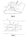
- FIGS. 2 and 3 illustrate an embodiment of a stall sensor 26 mounted or otherwise attached onto the low pressure surface 24 of a wind turbine blade 12.
- the stall sensor 26 includes a stationary base 28 and a flap member 30 that pivots relative to the base 28 at a pivot axis 31.
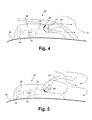
- the flap 31 pivots between a first position wherein laminar flow is generated over the low pressure surface 24, as indicated by the arrows in FIGS. 2 and 3 to a second position wherein the laminar flow is disrupted and backflow is induced at the low pressure surface 24, as indicated by the arrows in FIG. 5 .
- control circuitry 32 is particularly configured to respond to movement of the flap 30 from the first position illustrated in FIG. 4 to the second position illustrated in FIG. 5 , and to generate a corresponding electrical signal that indicates the stall condition depicted in FIG. 5 .
- Base member 28 may be mounted onto the surface of the turbine blade 12 by adhesive or other appropriate means, as indicated in FIGS. 4 and 5 .
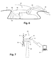
- the sensor 26 may be recessed within a recess 25 in the turbine blade low pressure surface 24, as depicted in FIG. 6 .
- the first position of the flap 30 is elevated as compared to the embodiment of FIGS. 4 and 5 so as to lie essentially flush or slightly above the low pressure surface 24.
- the flap 30 may include a raised lip 35 to ensure that the flap 30 reacts to backflow conditions over the low pressure surface 24.
- the stall sensor 26, and more particularly the sensor circuit 32 may incorporate any manner of known technique for converting movement of the flap 30 into an electrical signal.
- the sensor circuit 32 includes an open circuit 33.
- the flap 30 includes a contact 40 located on a surface that slides against the base 28 upon movement of the flap 30 from the first position to the second position. In the second position of the flap 30 as indicated in FIG. 5 , the contact 40 closes the circuit 33. With the closed circuit 33, any characteristic of the circuit may be sensed by the sensor circuit 32, such as a voltage, resistance, current, and so forth.
- FIGS. 4 the type of circuit illustrated in FIGS.
- the stall sensor 26 may be configured to generate a quantitative indication of the relative degree of movement of the flap 30.
- the circuit 32 may measure a change in a circuit characteristic, such as voltage or resistance, which varies with relative movement of the flap 30.
- a circuit characteristic such as voltage or resistance
- the circuit 32 may include any manner of rheostat, potentiometer, pressure transducer, strain gauge, or any other suitable device to measure relative motion of the flap 30 relative to the base 28.
- the flap 30 may be biased towards the first position by way of a spring or other biasing member, and a load cell may be utilized to measure resistance of the flap 30 to backflow conditions, with the magnitude of resistance giving a quantitative indication of the stall condition at the low pressure surface 24 of the turbine blade 12.
- the transducer circuit 32 illustrated in FIG. 6 is intended to encompass any manner of electrical, electrical-mechanical, or mechanical device that generates a signal in response to movement of the flap 30 relative to the base 28.
- the stall sensor 26 transmits the generated signal as an electrical signal.
- the senor 26 includes a dedicated power supply 44, such as an internal battery.
- the batteries 44 may be recharged from the nacelle controller, or periodically replaced.
- the sensor circuit 32 may be supplied power from the nacelle controller via the transmission lines 27 ( FIG. 1 ).
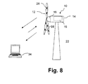
- the signal from the stall sensor 26 indicative of a stall condition may be transmitted and processed in various ways depending on the control configuration of the individual wind turbine 10.
- a remote receiver 34 which may be any manner of control hardware, may be in wireless communication with the wind turbine 10 via a transmitter/receiver 36 configured with the nacelle controller 15.
- the individual stall sensors 26 may be in wired or wireless communication with the nacelle controller 15 and, via this configuration, the signals from the stalls sensors 26 may be communicated to the remote receiver 34 as an alarm condition, or as an input to any manner of control function, such as pitch control of the turbine blades 12, and so forth.
- the individual stall sensors 26 may be configured to wirelessly transmit directly to the remote receiver 34.
- each of the stall sensors 26 is configured with a transmitter for this purpose. This embodiment would require a more robust power supply for the individual stall sensors 26. It should be readily appreciated that any manner of transmission system may be utilized for transmitting the control signals from the individual stall sensors 26 to any manner of controller for indication of a stall condition and/or control function.
- the signals and information generated by the stall sensors 26 may further aid in the understanding of reversed flow on a turbine blade 12, and to incorporate this knowledge into different turbine blade designs to avoid adverse flow phenomena at the turbine blades.
- the stall sensors 26 may be used to monitor blade fouling that is believed to be a cause of stall/reserved flow, and that leads to a significant degradation of the wind turbine performance.
- the stall sensors may be used to evaluate the correlation between stall and blade fouling, and provide a means for field service teams to quantify and analyze the impact of blade fouling in terms of lost energy, repairs, warranty claims, and the like.
- the stall sensors may also be incorporated into the turbine controller to detect stall and drive the turbine out of the stall condition.
Landscapes
- Engineering & Computer Science (AREA)
- Life Sciences & Earth Sciences (AREA)
- Sustainable Development (AREA)
- Sustainable Energy (AREA)
- Chemical & Material Sciences (AREA)
- Combustion & Propulsion (AREA)
- Mechanical Engineering (AREA)
- General Engineering & Computer Science (AREA)
- Wind Motors (AREA)
Applications Claiming Priority (1)
| Application Number | Priority Date | Filing Date | Title |
|---|---|---|---|
| US12/433,007 US7896614B2 (en) | 2009-04-30 | 2009-04-30 | Wind turbine blade with integrated stall sensor and associated method of detecting stall of a wind turbine blade |
Publications (3)
| Publication Number | Publication Date |
|---|---|
| EP2246559A2 true EP2246559A2 (fr) | 2010-11-03 |
| EP2246559A3 EP2246559A3 (fr) | 2014-05-14 |
| EP2246559B1 EP2246559B1 (fr) | 2015-07-08 |
Family
ID=42224566
Family Applications (1)
| Application Number | Title | Priority Date | Filing Date |
|---|---|---|---|
| EP10160819.8A Not-in-force EP2246559B1 (fr) | 2009-04-30 | 2010-04-23 | Pale d'éolienne avec capteurs intégrés pour le contrôle du décrochage et procédé de détection du décrochage d'une pale d'éolienne |
Country Status (5)
| Country | Link |
|---|---|
| US (1) | US7896614B2 (fr) |
| EP (1) | EP2246559B1 (fr) |
| CN (1) | CN101876294B (fr) |
| DK (1) | DK2246559T3 (fr) |
| ES (1) | ES2544590T3 (fr) |
Cited By (3)
| Publication number | Priority date | Publication date | Assignee | Title |
|---|---|---|---|---|
| US9593670B2 (en) | 2014-04-30 | 2017-03-14 | General Electric Company | System and methods for reducing wind turbine noise |
| US9658124B2 (en) | 2014-11-05 | 2017-05-23 | General Electric Company | System and method for wind turbine operation |
| WO2022268929A1 (fr) | 2021-06-23 | 2022-12-29 | Voisin Dimitri Marcel | Dispositif pour la détection de décollement et ensemble pour un tel dispositif |
Families Citing this family (20)
| Publication number | Priority date | Publication date | Assignee | Title |
|---|---|---|---|---|
| US8573937B2 (en) | 2008-11-21 | 2013-11-05 | Xzeres Corp. | System for providing dynamic pitch control in a wind turbine |
| US20100135790A1 (en) * | 2009-10-14 | 2010-06-03 | Sujan Kumar Pal | Wind turbine blade with foreign matter detection devices |
| US20120299747A1 (en) * | 2009-11-13 | 2012-11-29 | Schaeffler Technologies AG & Co. KG | Remote condition monitoring system and method |
| US8516899B2 (en) * | 2010-10-06 | 2013-08-27 | Siemens Energy, Inc. | System for remote monitoring of aerodynamic flow conditions |
| US8267655B2 (en) * | 2010-12-20 | 2012-09-18 | General Electric Company | Method for controlling a wind turbine, and wind turbine arrangement |
| TW201309906A (zh) | 2011-03-07 | 2013-03-01 | Mcpherson Performance Blade Llc | 具改善效能的風力渦輪轉子葉片 |
| US9753050B2 (en) | 2013-02-15 | 2017-09-05 | Vestas Wind Systems A/S | Wind turbine component having an optical fibre wind sensor |
| US9528493B2 (en) | 2013-05-28 | 2016-12-27 | Siemens Aktiengesellschaft | Apparatus to detect aerodynamic conditions of blades of wind turbines |
| DK2857677T3 (en) | 2013-10-01 | 2018-07-02 | Siemens Ag | Adjusting a rotor blade pitch angle |
| WO2016066170A1 (fr) * | 2014-10-29 | 2016-05-06 | Vestas Wind Systems A/S | Capteur de turbulences pour éoliennes |
| US10156224B2 (en) * | 2015-03-13 | 2018-12-18 | General Electric Company | System and method for controlling a wind turbine |
| DE102016004854A1 (de) | 2016-04-22 | 2017-10-26 | Dominic Czempas | Strömungssensor zur Erkennung und Signalisierung von Strömungszuständen, insbesondere eines Strömungsabrisses |
| EP3622176B1 (fr) * | 2017-07-14 | 2021-05-26 | Siemens Gamesa Renewable Energy A/S | Détermination d'au moins une caractéristique d'une couche limite d'une pale de rotor d'éolienne |
| EP3543522A1 (fr) * | 2018-03-22 | 2019-09-25 | Siemens Gamesa Renewable Energy A/S | Système de surveillance de pale de rotor |
| US11261845B2 (en) * | 2018-07-26 | 2022-03-01 | General Electric Company | System and method for protecting wind turbines during extreme wind direction change |
| US20210047995A1 (en) * | 2019-08-15 | 2021-02-18 | Marinvent Corporation | Airfoil Performance Monitor |
| US11499484B2 (en) | 2020-07-27 | 2022-11-15 | Signal Power Group Operating Llc | System for controlling a turbine |
| CN112796931B (zh) * | 2020-12-30 | 2023-06-02 | 西安利和愽机械制造有限公司 | 一种风力扰流结构 |
| CN115929565A (zh) * | 2022-11-22 | 2023-04-07 | 中材科技风电叶片股份有限公司 | 风电机组、风电叶片及风电叶片截面翼型的失速监测方法 |
| CN115962101B (zh) * | 2022-12-05 | 2024-03-22 | 中材科技风电叶片股份有限公司 | 一种失速状态监测方法及系统 |
Citations (1)
| Publication number | Priority date | Publication date | Assignee | Title |
|---|---|---|---|---|
| US6065334A (en) | 1996-05-17 | 2000-05-23 | Stichting Energieonderzoek Centrum Nederland | Device for rendering visible the fluid flow over a surface |
Family Cites Families (9)
| Publication number | Priority date | Publication date | Assignee | Title |
|---|---|---|---|---|
| US2373089A (en) * | 1940-11-02 | 1945-04-10 | Boeing Aircraft Co | Stall delaying and indicating mechanism |
| US2486779A (en) * | 1943-11-22 | 1949-11-01 | Us Commerce | Stall warning indicator |
| US2603695A (en) * | 1944-04-11 | 1952-07-15 | United Aircraft Corp | Ionized air stall detector |
| US2431241A (en) * | 1944-09-19 | 1947-11-18 | Westinghouse Electric Corp | Stall warning indicating apparatus |
| US2748372A (en) * | 1953-10-16 | 1956-05-29 | Northrop Aircraft Inc | Stall warning device |
| US4427897A (en) | 1982-01-18 | 1984-01-24 | John Midyette, III | Fixed pitch wind turbine system utilizing aerodynamic stall |
| DE4443665C2 (de) * | 1994-12-08 | 1999-02-11 | Helmut Dipl Ing Fritz | Strömungssensor |
| CN100335776C (zh) * | 2002-02-25 | 2007-09-05 | 伊斯克拉风涡轮机有限公司 | 风力涡轮机的被动速度和电力调节 |
| US6941816B2 (en) * | 2003-11-25 | 2005-09-13 | Kulite Semiconductor Products, Inc. | Transducer with integral switch for wireless electronics |
-
2009
- 2009-04-30 US US12/433,007 patent/US7896614B2/en not_active Expired - Fee Related
-
2010
- 2010-04-23 ES ES10160819.8T patent/ES2544590T3/es active Active
- 2010-04-23 EP EP10160819.8A patent/EP2246559B1/fr not_active Not-in-force
- 2010-04-23 DK DK10160819.8T patent/DK2246559T3/en active
- 2010-04-30 CN CN2010101754794A patent/CN101876294B/zh not_active Expired - Fee Related
Patent Citations (1)
| Publication number | Priority date | Publication date | Assignee | Title |
|---|---|---|---|---|
| US6065334A (en) | 1996-05-17 | 2000-05-23 | Stichting Energieonderzoek Centrum Nederland | Device for rendering visible the fluid flow over a surface |
Cited By (4)
| Publication number | Priority date | Publication date | Assignee | Title |
|---|---|---|---|---|
| US9593670B2 (en) | 2014-04-30 | 2017-03-14 | General Electric Company | System and methods for reducing wind turbine noise |
| US9658124B2 (en) | 2014-11-05 | 2017-05-23 | General Electric Company | System and method for wind turbine operation |
| WO2022268929A1 (fr) | 2021-06-23 | 2022-12-29 | Voisin Dimitri Marcel | Dispositif pour la détection de décollement et ensemble pour un tel dispositif |
| FR3124595A1 (fr) | 2021-06-23 | 2022-12-30 | Marcel Voisin Dimitri | Dispositif pour la détection de décollement et ensemble pour un tel dispositif |
Also Published As
| Publication number | Publication date |
|---|---|
| US7896614B2 (en) | 2011-03-01 |
| EP2246559B1 (fr) | 2015-07-08 |
| CN101876294A (zh) | 2010-11-03 |
| EP2246559A3 (fr) | 2014-05-14 |
| US20100143129A1 (en) | 2010-06-10 |
| CN101876294B (zh) | 2013-07-17 |
| DK2246559T3 (en) | 2015-08-03 |
| ES2544590T3 (es) | 2015-09-01 |
Similar Documents
| Publication | Publication Date | Title |
|---|---|---|
| EP2246559B1 (fr) | Pale d'éolienne avec capteurs intégrés pour le contrôle du décrochage et procédé de détection du décrochage d'une pale d'éolienne | |
| EP2559892B1 (fr) | Procede de surveillance d'eoliennes | |
| EP2345943A1 (fr) | Système et procédé de surveillance et de contrôle de déflection de pale d'éolienne | |
| DK2287464T3 (en) | Passive de-icing for wind turbine blades | |
| US20090232635A1 (en) | Independent sensing system for wind turbines | |
| EP2910777B1 (fr) | Vitesse dynamique de vent minimum de démarrage pour éoliennes | |
| US8231344B2 (en) | Methods for controlling the amplitude modulation of noise generated by wind turbines | |
| EP2148088A1 (fr) | Procédé et arrangement pour le réglage d'angle de calage des pales d'éolienne | |
| DK178811B1 (en) | Methods and systems for reducing amplitude modulation in wind turbines | |
| EP2469081B1 (fr) | Système de contrôle, parc éolien et procédés d'optimisation du fonctionnement d'une éolienne | |
| EP2644887A2 (fr) | Procédé de prévention de décrochage aérodynamique dans des turbines éoliennes | |
| EP2112375A3 (fr) | Détection de givrage pour éolienne | |
| US11261845B2 (en) | System and method for protecting wind turbines during extreme wind direction change | |
| EP3249218B1 (fr) | Système et procédé d'implantation d'un parc éolien pour optimiser les charges | |
| ES2909373T3 (es) | Sistema y método para operar turbinas eólicas para evitar la entrada en pérdida mientras opera con reducción de potencia | |
| EP2175127A3 (fr) | Eolienne, appareillage de surveillance environnementale et procédé pour mesurer les conditions environnementales d'une éolienne | |
| EP3643914B1 (fr) | Système et procédé pour protéger des éoliennes contre les charges extrêmes et de fatigue | |
| JP2022107523A (ja) | 風の乱流のアクティブセンシングを用いた風力タービンのための推力制御 | |
| DK201670502A1 (en) | Wind turbine and a method of operating a wind turbine | |
| KR20100055291A (ko) | 풍력 발전 시스템 | |
| CN101476538A (zh) | 用于风力涡轮机的单个叶片噪声测量系统和方法 | |
| JP6258339B2 (ja) | 風車装置、風車装置の異常検出装置及び風車装置の異常検出方法 | |
| US9920744B2 (en) | System and method for detecting rotor asymmetry | |
| EP3415752A1 (fr) | Commande de vitesse nominale variable dans un fonctionnement en charge partielle d'une éolienne | |
| CN113586359B (zh) | 用于响应于叶片脱落事件而控制风力涡轮的系统和方法 |
Legal Events
| Date | Code | Title | Description |
|---|---|---|---|
| PUAI | Public reference made under article 153(3) epc to a published international application that has entered the european phase |
Free format text: ORIGINAL CODE: 0009012 |
|
| AK | Designated contracting states |
Kind code of ref document: A2 Designated state(s): AT BE BG CH CY CZ DE DK EE ES FI FR GB GR HR HU IE IS IT LI LT LU LV MC MK MT NL NO PL PT RO SE SI SK SM TR |
|
| PUAL | Search report despatched |
Free format text: ORIGINAL CODE: 0009013 |
|
| AK | Designated contracting states |
Kind code of ref document: A3 Designated state(s): AT BE BG CH CY CZ DE DK EE ES FI FR GB GR HR HU IE IS IT LI LT LU LV MC MK MT NL NO PL PT RO SE SI SK SM TR |
|
| RIC1 | Information provided on ipc code assigned before grant |
Ipc: F03D 7/02 20060101AFI20140404BHEP Ipc: F03D 7/00 20060101ALI20140404BHEP |
|
| 17P | Request for examination filed |
Effective date: 20141114 |
|
| RBV | Designated contracting states (corrected) |
Designated state(s): AT BE BG CH CY CZ DE DK EE ES FI FR GB GR HR HU IE IS IT LI LT LU LV MC MK MT NL NO PL PT RO SE SI SK SM TR |
|
| RIC1 | Information provided on ipc code assigned before grant |
Ipc: F03D 7/02 20060101AFI20150225BHEP Ipc: F03D 7/00 20060101ALI20150225BHEP |
|
| GRAP | Despatch of communication of intention to grant a patent |
Free format text: ORIGINAL CODE: EPIDOSNIGR1 |
|
| INTG | Intention to grant announced |
Effective date: 20150409 |
|
| GRAS | Grant fee paid |
Free format text: ORIGINAL CODE: EPIDOSNIGR3 |
|
| GRAA | (expected) grant |
Free format text: ORIGINAL CODE: 0009210 |
|
| AK | Designated contracting states |
Kind code of ref document: B1 Designated state(s): AT BE BG CH CY CZ DE DK EE ES FI FR GB GR HR HU IE IS IT LI LT LU LV MC MK MT NL NO PL PT RO SE SI SK SM TR |
|
| REG | Reference to a national code |
Ref country code: GB Ref legal event code: FG4D |
|
| REG | Reference to a national code |
Ref country code: AT Ref legal event code: REF Ref document number: 735625 Country of ref document: AT Kind code of ref document: T Effective date: 20150715 Ref country code: CH Ref legal event code: EP |
|
| REG | Reference to a national code |
Ref country code: DK Ref legal event code: T3 Effective date: 20150728 |
|
| REG | Reference to a national code |
Ref country code: IE Ref legal event code: FG4D |
|
| REG | Reference to a national code |
Ref country code: DE Ref legal event code: R096 Ref document number: 602010025669 Country of ref document: DE |
|
| REG | Reference to a national code |
Ref country code: ES Ref legal event code: FG2A Ref document number: 2544590 Country of ref document: ES Kind code of ref document: T3 Effective date: 20150901 |
|
| REG | Reference to a national code |
Ref country code: AT Ref legal event code: MK05 Ref document number: 735625 Country of ref document: AT Kind code of ref document: T Effective date: 20150708 |
|
| REG | Reference to a national code |
Ref country code: NL Ref legal event code: MP Effective date: 20150708 |
|
| REG | Reference to a national code |
Ref country code: LT Ref legal event code: MG4D |
|
| PG25 | Lapsed in a contracting state [announced via postgrant information from national office to epo] |
Ref country code: LT Free format text: LAPSE BECAUSE OF FAILURE TO SUBMIT A TRANSLATION OF THE DESCRIPTION OR TO PAY THE FEE WITHIN THE PRESCRIBED TIME-LIMIT Effective date: 20150708 Ref country code: LV Free format text: LAPSE BECAUSE OF FAILURE TO SUBMIT A TRANSLATION OF THE DESCRIPTION OR TO PAY THE FEE WITHIN THE PRESCRIBED TIME-LIMIT Effective date: 20150708 Ref country code: NO Free format text: LAPSE BECAUSE OF FAILURE TO SUBMIT A TRANSLATION OF THE DESCRIPTION OR TO PAY THE FEE WITHIN THE PRESCRIBED TIME-LIMIT Effective date: 20151008 Ref country code: GR Free format text: LAPSE BECAUSE OF FAILURE TO SUBMIT A TRANSLATION OF THE DESCRIPTION OR TO PAY THE FEE WITHIN THE PRESCRIBED TIME-LIMIT Effective date: 20151009 Ref country code: FI Free format text: LAPSE BECAUSE OF FAILURE TO SUBMIT A TRANSLATION OF THE DESCRIPTION OR TO PAY THE FEE WITHIN THE PRESCRIBED TIME-LIMIT Effective date: 20150708 |
|
| PG25 | Lapsed in a contracting state [announced via postgrant information from national office to epo] |
Ref country code: IS Free format text: LAPSE BECAUSE OF FAILURE TO SUBMIT A TRANSLATION OF THE DESCRIPTION OR TO PAY THE FEE WITHIN THE PRESCRIBED TIME-LIMIT Effective date: 20151108 Ref country code: AT Free format text: LAPSE BECAUSE OF FAILURE TO SUBMIT A TRANSLATION OF THE DESCRIPTION OR TO PAY THE FEE WITHIN THE PRESCRIBED TIME-LIMIT Effective date: 20150708 Ref country code: PT Free format text: LAPSE BECAUSE OF FAILURE TO SUBMIT A TRANSLATION OF THE DESCRIPTION OR TO PAY THE FEE WITHIN THE PRESCRIBED TIME-LIMIT Effective date: 20151109 Ref country code: PL Free format text: LAPSE BECAUSE OF FAILURE TO SUBMIT A TRANSLATION OF THE DESCRIPTION OR TO PAY THE FEE WITHIN THE PRESCRIBED TIME-LIMIT Effective date: 20150708 Ref country code: SE Free format text: LAPSE BECAUSE OF FAILURE TO SUBMIT A TRANSLATION OF THE DESCRIPTION OR TO PAY THE FEE WITHIN THE PRESCRIBED TIME-LIMIT Effective date: 20150708 Ref country code: HR Free format text: LAPSE BECAUSE OF FAILURE TO SUBMIT A TRANSLATION OF THE DESCRIPTION OR TO PAY THE FEE WITHIN THE PRESCRIBED TIME-LIMIT Effective date: 20150708 |
|
| REG | Reference to a national code |
Ref country code: DE Ref legal event code: R097 Ref document number: 602010025669 Country of ref document: DE |
|
| PG25 | Lapsed in a contracting state [announced via postgrant information from national office to epo] |
Ref country code: IT Free format text: LAPSE BECAUSE OF FAILURE TO SUBMIT A TRANSLATION OF THE DESCRIPTION OR TO PAY THE FEE WITHIN THE PRESCRIBED TIME-LIMIT Effective date: 20150708 Ref country code: CZ Free format text: LAPSE BECAUSE OF FAILURE TO SUBMIT A TRANSLATION OF THE DESCRIPTION OR TO PAY THE FEE WITHIN THE PRESCRIBED TIME-LIMIT Effective date: 20150708 Ref country code: SK Free format text: LAPSE BECAUSE OF FAILURE TO SUBMIT A TRANSLATION OF THE DESCRIPTION OR TO PAY THE FEE WITHIN THE PRESCRIBED TIME-LIMIT Effective date: 20150708 Ref country code: EE Free format text: LAPSE BECAUSE OF FAILURE TO SUBMIT A TRANSLATION OF THE DESCRIPTION OR TO PAY THE FEE WITHIN THE PRESCRIBED TIME-LIMIT Effective date: 20150708 |
|
| PLBE | No opposition filed within time limit |
Free format text: ORIGINAL CODE: 0009261 |
|
| STAA | Information on the status of an ep patent application or granted ep patent |
Free format text: STATUS: NO OPPOSITION FILED WITHIN TIME LIMIT |
|
| PG25 | Lapsed in a contracting state [announced via postgrant information from national office to epo] |
Ref country code: RO Free format text: LAPSE BECAUSE OF FAILURE TO SUBMIT A TRANSLATION OF THE DESCRIPTION OR TO PAY THE FEE WITHIN THE PRESCRIBED TIME-LIMIT Effective date: 20150708 |
|
| 26N | No opposition filed |
Effective date: 20160411 |
|
| PG25 | Lapsed in a contracting state [announced via postgrant information from national office to epo] |
Ref country code: BE Free format text: LAPSE BECAUSE OF NON-PAYMENT OF DUE FEES Effective date: 20160430 Ref country code: SI Free format text: LAPSE BECAUSE OF FAILURE TO SUBMIT A TRANSLATION OF THE DESCRIPTION OR TO PAY THE FEE WITHIN THE PRESCRIBED TIME-LIMIT Effective date: 20150708 |
|
| REG | Reference to a national code |
Ref country code: CH Ref legal event code: PL |
|
| GBPC | Gb: european patent ceased through non-payment of renewal fee |
Effective date: 20160423 |
|
| PG25 | Lapsed in a contracting state [announced via postgrant information from national office to epo] |
Ref country code: BE Free format text: LAPSE BECAUSE OF FAILURE TO SUBMIT A TRANSLATION OF THE DESCRIPTION OR TO PAY THE FEE WITHIN THE PRESCRIBED TIME-LIMIT Effective date: 20150708 Ref country code: LU Free format text: LAPSE BECAUSE OF FAILURE TO SUBMIT A TRANSLATION OF THE DESCRIPTION OR TO PAY THE FEE WITHIN THE PRESCRIBED TIME-LIMIT Effective date: 20160423 |
|
| REG | Reference to a national code |
Ref country code: IE Ref legal event code: MM4A |
|
| REG | Reference to a national code |
Ref country code: FR Ref legal event code: ST Effective date: 20161230 |
|
| PG25 | Lapsed in a contracting state [announced via postgrant information from national office to epo] |
Ref country code: LI Free format text: LAPSE BECAUSE OF NON-PAYMENT OF DUE FEES Effective date: 20160430 Ref country code: CH Free format text: LAPSE BECAUSE OF NON-PAYMENT OF DUE FEES Effective date: 20160430 Ref country code: GB Free format text: LAPSE BECAUSE OF NON-PAYMENT OF DUE FEES Effective date: 20160423 Ref country code: FR Free format text: LAPSE BECAUSE OF NON-PAYMENT OF DUE FEES Effective date: 20160502 |
|
| PG25 | Lapsed in a contracting state [announced via postgrant information from national office to epo] |
Ref country code: IE Free format text: LAPSE BECAUSE OF NON-PAYMENT OF DUE FEES Effective date: 20160423 |
|
| PG25 | Lapsed in a contracting state [announced via postgrant information from national office to epo] |
Ref country code: NL Free format text: LAPSE BECAUSE OF FAILURE TO SUBMIT A TRANSLATION OF THE DESCRIPTION OR TO PAY THE FEE WITHIN THE PRESCRIBED TIME-LIMIT Effective date: 20150708 |
|
| PG25 | Lapsed in a contracting state [announced via postgrant information from national office to epo] |
Ref country code: HU Free format text: LAPSE BECAUSE OF FAILURE TO SUBMIT A TRANSLATION OF THE DESCRIPTION OR TO PAY THE FEE WITHIN THE PRESCRIBED TIME-LIMIT; INVALID AB INITIO Effective date: 20100423 Ref country code: SM Free format text: LAPSE BECAUSE OF FAILURE TO SUBMIT A TRANSLATION OF THE DESCRIPTION OR TO PAY THE FEE WITHIN THE PRESCRIBED TIME-LIMIT Effective date: 20150708 Ref country code: CY Free format text: LAPSE BECAUSE OF FAILURE TO SUBMIT A TRANSLATION OF THE DESCRIPTION OR TO PAY THE FEE WITHIN THE PRESCRIBED TIME-LIMIT Effective date: 20150708 |
|
| PG25 | Lapsed in a contracting state [announced via postgrant information from national office to epo] |
Ref country code: TR Free format text: LAPSE BECAUSE OF FAILURE TO SUBMIT A TRANSLATION OF THE DESCRIPTION OR TO PAY THE FEE WITHIN THE PRESCRIBED TIME-LIMIT Effective date: 20150708 Ref country code: MK Free format text: LAPSE BECAUSE OF FAILURE TO SUBMIT A TRANSLATION OF THE DESCRIPTION OR TO PAY THE FEE WITHIN THE PRESCRIBED TIME-LIMIT Effective date: 20150708 Ref country code: MT Free format text: LAPSE BECAUSE OF NON-PAYMENT OF DUE FEES Effective date: 20160430 Ref country code: MC Free format text: LAPSE BECAUSE OF FAILURE TO SUBMIT A TRANSLATION OF THE DESCRIPTION OR TO PAY THE FEE WITHIN THE PRESCRIBED TIME-LIMIT Effective date: 20150708 |
|
| PG25 | Lapsed in a contracting state [announced via postgrant information from national office to epo] |
Ref country code: BG Free format text: LAPSE BECAUSE OF FAILURE TO SUBMIT A TRANSLATION OF THE DESCRIPTION OR TO PAY THE FEE WITHIN THE PRESCRIBED TIME-LIMIT Effective date: 20150708 |
|
| PGFP | Annual fee paid to national office [announced via postgrant information from national office to epo] |
Ref country code: DE Payment date: 20180427 Year of fee payment: 9 Ref country code: DK Payment date: 20180426 Year of fee payment: 9 Ref country code: ES Payment date: 20180503 Year of fee payment: 9 |
|
| REG | Reference to a national code |
Ref country code: DE Ref legal event code: R119 Ref document number: 602010025669 Country of ref document: DE |
|
| REG | Reference to a national code |
Ref country code: DK Ref legal event code: EBP Effective date: 20190430 |
|
| PG25 | Lapsed in a contracting state [announced via postgrant information from national office to epo] |
Ref country code: DE Free format text: LAPSE BECAUSE OF NON-PAYMENT OF DUE FEES Effective date: 20191101 |
|
| PG25 | Lapsed in a contracting state [announced via postgrant information from national office to epo] |
Ref country code: DK Free format text: LAPSE BECAUSE OF NON-PAYMENT OF DUE FEES Effective date: 20190430 |
|
| REG | Reference to a national code |
Ref country code: ES Ref legal event code: FD2A Effective date: 20200901 |
|
| PG25 | Lapsed in a contracting state [announced via postgrant information from national office to epo] |
Ref country code: ES Free format text: LAPSE BECAUSE OF NON-PAYMENT OF DUE FEES Effective date: 20190424 |