EP2246583B1 - Cage pour joint universel homocinétique - Google Patents
Cage pour joint universel homocinétique Download PDFInfo
- Publication number
- EP2246583B1 EP2246583B1 EP09705154.4A EP09705154A EP2246583B1 EP 2246583 B1 EP2246583 B1 EP 2246583B1 EP 09705154 A EP09705154 A EP 09705154A EP 2246583 B1 EP2246583 B1 EP 2246583B1
- Authority
- EP
- European Patent Office
- Prior art keywords
- diameter surface
- corresponds
- joint member
- range
- axial center
- Prior art date
- Legal status (The legal status is an assumption and is not a legal conclusion. Google has not performed a legal analysis and makes no representation as to the accuracy of the status listed.)
- Not-in-force
Links
- 230000003746 surface roughness Effects 0.000 claims description 96
- 238000005520 cutting process Methods 0.000 description 12
- 238000003754 machining Methods 0.000 description 9
- 238000010791 quenching Methods 0.000 description 8
- 230000000171 quenching effect Effects 0.000 description 8
- 229910000831 Steel Inorganic materials 0.000 description 4
- 238000004519 manufacturing process Methods 0.000 description 4
- 235000019592 roughness Nutrition 0.000 description 4
- 239000010959 steel Substances 0.000 description 4
- 230000003245 working effect Effects 0.000 description 4
- 238000005299 abrasion Methods 0.000 description 3
- 230000006698 induction Effects 0.000 description 3
- 238000000034 method Methods 0.000 description 3
- 230000005540 biological transmission Effects 0.000 description 2
- 238000001723 curing Methods 0.000 description 2
- 238000001029 thermal curing Methods 0.000 description 2
- 229910000954 Medium-carbon steel Inorganic materials 0.000 description 1
- 238000005255 carburizing Methods 0.000 description 1
- 238000010586 diagram Methods 0.000 description 1
- 230000000694 effects Effects 0.000 description 1
- 239000000463 material Substances 0.000 description 1
- 238000005259 measurement Methods 0.000 description 1
- 238000012986 modification Methods 0.000 description 1
- 230000004048 modification Effects 0.000 description 1
- 238000005121 nitriding Methods 0.000 description 1
- 230000000717 retained effect Effects 0.000 description 1
- 238000005096 rolling process Methods 0.000 description 1
Images

Classifications
-
- F—MECHANICAL ENGINEERING; LIGHTING; HEATING; WEAPONS; BLASTING
- F16—ENGINEERING ELEMENTS AND UNITS; GENERAL MEASURES FOR PRODUCING AND MAINTAINING EFFECTIVE FUNCTIONING OF MACHINES OR INSTALLATIONS; THERMAL INSULATION IN GENERAL
- F16D—COUPLINGS FOR TRANSMITTING ROTATION; CLUTCHES; BRAKES
- F16D3/00—Yielding couplings, i.e. with means permitting movement between the connected parts during the drive
- F16D3/16—Universal joints in which flexibility is produced by means of pivots or sliding or rolling connecting parts
- F16D3/20—Universal joints in which flexibility is produced by means of pivots or sliding or rolling connecting parts one coupling part entering a sleeve of the other coupling part and connected thereto by sliding or rolling members
- F16D3/22—Universal joints in which flexibility is produced by means of pivots or sliding or rolling connecting parts one coupling part entering a sleeve of the other coupling part and connected thereto by sliding or rolling members the rolling members being balls, rollers, or the like, guided in grooves or sockets in both coupling parts
- F16D3/223—Universal joints in which flexibility is produced by means of pivots or sliding or rolling connecting parts one coupling part entering a sleeve of the other coupling part and connected thereto by sliding or rolling members the rolling members being balls, rollers, or the like, guided in grooves or sockets in both coupling parts the rolling members being guided in grooves in both coupling parts
- F16D3/224—Universal joints in which flexibility is produced by means of pivots or sliding or rolling connecting parts one coupling part entering a sleeve of the other coupling part and connected thereto by sliding or rolling members the rolling members being balls, rollers, or the like, guided in grooves or sockets in both coupling parts the rolling members being guided in grooves in both coupling parts the groove centre-lines in each coupling part lying on a sphere
- F16D3/2245—Universal joints in which flexibility is produced by means of pivots or sliding or rolling connecting parts one coupling part entering a sleeve of the other coupling part and connected thereto by sliding or rolling members the rolling members being balls, rollers, or the like, guided in grooves or sockets in both coupling parts the rolling members being guided in grooves in both coupling parts the groove centre-lines in each coupling part lying on a sphere where the groove centres are offset from the joint centre
-
- F—MECHANICAL ENGINEERING; LIGHTING; HEATING; WEAPONS; BLASTING
- F16—ENGINEERING ELEMENTS AND UNITS; GENERAL MEASURES FOR PRODUCING AND MAINTAINING EFFECTIVE FUNCTIONING OF MACHINES OR INSTALLATIONS; THERMAL INSULATION IN GENERAL
- F16D—COUPLINGS FOR TRANSMITTING ROTATION; CLUTCHES; BRAKES
- F16D3/00—Yielding couplings, i.e. with means permitting movement between the connected parts during the drive
- F16D3/16—Universal joints in which flexibility is produced by means of pivots or sliding or rolling connecting parts
- F16D3/20—Universal joints in which flexibility is produced by means of pivots or sliding or rolling connecting parts one coupling part entering a sleeve of the other coupling part and connected thereto by sliding or rolling members
- F16D3/22—Universal joints in which flexibility is produced by means of pivots or sliding or rolling connecting parts one coupling part entering a sleeve of the other coupling part and connected thereto by sliding or rolling members the rolling members being balls, rollers, or the like, guided in grooves or sockets in both coupling parts
- F16D3/223—Universal joints in which flexibility is produced by means of pivots or sliding or rolling connecting parts one coupling part entering a sleeve of the other coupling part and connected thereto by sliding or rolling members the rolling members being balls, rollers, or the like, guided in grooves or sockets in both coupling parts the rolling members being guided in grooves in both coupling parts
- F16D2003/22303—Details of ball cages
-
- F—MECHANICAL ENGINEERING; LIGHTING; HEATING; WEAPONS; BLASTING
- F16—ENGINEERING ELEMENTS AND UNITS; GENERAL MEASURES FOR PRODUCING AND MAINTAINING EFFECTIVE FUNCTIONING OF MACHINES OR INSTALLATIONS; THERMAL INSULATION IN GENERAL
- F16D—COUPLINGS FOR TRANSMITTING ROTATION; CLUTCHES; BRAKES
- F16D2250/00—Manufacturing; Assembly
- F16D2250/003—Chip removing
Definitions
- the present invention relates to a cage for a constant velocity universal joint, and more particularly, to a cage for a constant velocity universal joint of a fixed type, which is used in a power transmission system in an automobile or various industrial machines and in which balls are used as rolling bodies.
- a constant velocity universal joint is provided with an outer joint member which has track grooves formed on an inner diameter side thereof, an inner joint member which has track grooves formed in an outer diameter side thereof, multiple balls which are interposed between the track grooves of the outer joint member and the track grooves of the inner joint member so as to transmit torque, and a cage which is interposed between the inner diameter surface of the outer joint member and the outer diameter surface of the inner joint member so as to hold the balls.
- the outer diameter surface and the inner diameter surface of the cage are brought into contact with the outer race as the outer joint member and an inner race as the inner joint member.
- machining machining of quenched steel
- quenching thermal curing process
- the inner diameter surface and the outer diameter surface of the cage secure the dimensional accuracy and the surface roughness thereof (Patent Document 1).
- Patent Document 1 in the case of machining the cage after quenching, the cage is finished such that the surface roughness of the outer diameter surface and the inner diameter surface thereof is uniform over the entire region extending from one end side to the other end side thereof.
- the machining is generally performed from the end side which corresponds to the inlet side of the outer race to the end side which corresponds to the inner side of the outer race. Therefore, in a range extending from the center of the outer diameter surface of the cage to the end side which corresponds to the inner side of the outer race, the surface roughness is reduced in accordance with the abrasion of a tool. Meanwhile, in the case where the inner diameter surface of the cage is worked by machining of quenched steel, the machining is conversely performed from the end side which corresponds to the inner side of the outer race to the end side which corresponds to the inlet side of the outer race.
- the surface roughness is reduced in accordance with the abrasion of a tool.
- the life of the tool comes to an end at the time points.
- the life of the tool has a large influence on the manufacturing cost. Therefore, the extension of the life of the tool is demanded.
- the prior art document US 20021077186 A1 discloses a retainer for a constant velocity universal joint.
- the retainer includes a spherical outer surface being in contact with a spherical inner surface of an outer race and a spherical inner surface being in contact with a spherical outer surface of an inner race.
- the retainer has pockets for accommodating balls interposed between the outer race and the inner race.
- a cage for a constant velocity universal joint according to the present invention includes:
- the spherical surface roughness in the range extending from the axial center of the inner diameter surface to the end side which of the inner diameter surface corresponds to the opening side of the outer joint member is different from that in the range therefrom to the end side which of the inner diameter surface corresponds to the inner side, whereby any one of them can be roughly finished.
- the finishing which is performed with use of the cutting tool in the rough range can be roughly completed. That is, the criteria of the life of the tool can be relaxed in the rough range.
- the spherical surface roughness in the range extending from the axial center of the inner diameter surface to the end side of the inner diameter surface which corresponds to the opening side of the outer joint member be larger than the spherical surface roughness in the range extending from the axial center of the inner diameter surface to the end side of the inner diameter surface which corresponds to the inner side of the outer joint member.
- R2 ⁇ R1 ⁇ 2 ⁇ R2 when the spherical surface roughness in the range extending from the axial center of the inner diameter surface to the end side of the inner diameter surface which corresponds to the opening side of the outer joint member is R1, and the spherical surface roughness in the range extending from the axial center of the inner diameter surface to the end side of the inner diameter surface which corresponds to the inner side of the outer joint member is R2. It is also possible to set the spherical surface roughness in the range extending from the axial center of the inner diameter surface to the end side of the inner diameter surface which corresponds to the inner side of the outer joint member to be equal to or smaller than Ra: 0.8.
- a cage for a constant velocity universal joint includes:
- the spherical surface roughness in the range extending from the axial center of the outer diameter surface to the end side of the outer diameter surface which corresponds to the inner side of the outer joint member is different from that in the range extending therefrom to the end side of the outer diameter surface which corresponds to the opening side thereof, whereby any one of them can be roughly finished.
- the finishing which is performed with use of the cutting tool in the rough range can be roughly completed. That is, the criteria of the life of the tool can be relaxed in the rough range.
- the spherical surface roughness in the range extending from the axial center of the outer diameter surface to the end side of the outer diameter surface which corresponds to the inner side of the outer joint member be larger than the spherical surface roughness in the range extending from the axial center of the outer diameter surface to the end side of the outer diameter surface which corresponds to the opening side of the outer joint member.
- R4 ⁇ R3 ⁇ 2xR4 when the spherical surface roughness in the range extending from the axial center of the outer diameter surface to the end side of the outer diameter surface which corresponds to the inner side of the outer joint member is R3, and the spherical surface roughness in the range extending from the axial center of the outer diameter surface to the end side of the outer diameter surface which corresponds to the opening side of the outer joint member is R4. It is also possible to set the spherical surface roughness in the range extending from the axial center of the outer diameter surface to the end side of the outer diameter surface which corresponds to the opening side of the outer joint member to be equal to or smaller than Ra: 0.8.
- the finishing which is performed with use of the cutting tool in the rough range can be roughly completed.
- the criteria of the life of the tool can be relaxed in the rough range, and hence the life of the cutting tool can be extended, which leads to reduction in manufacturing cost.
- the track grooves of the outer joint member open on the inlet side (opening side), and hence the influence on the function of the constant velocity universal joint is small even when the spherical surface roughness in the range extending from the axial center of the inner diameter surface of the cage to the end side of the inner diameter surface which corresponds to the inlet side (opening side) thereof is large, or the spherical surface roughness in the range extending from the axial center of the outer diameter surface of the cage to the end side of the outer diameter surface which corresponds to the inner side thereof is large. Therefore, it is preferred that the spherical surface roughness in the range extending from the axial center to the end side which corresponds to the opening side of the outer joint member be large in the inner diameter surface of the cage. Further, it is preferred that the spherical surface roughness in the range extending from the axial center to the end side which corresponds to the inner side of the outer joint member be large in the outer diameter surface of the cage.
- the spherical surface roughness in the range extending from the axial center of the inner diameter surface of the cage to the end side of the inner diameter surface which corresponds to the inner side of the outer joint member, or the spherical surface roughness in the range extending from the axial center of the outer diameter surface of the cage to the end side of the outer diameter surface which corresponds to the opening side of the outer joint member is set to be equal to or smaller than Ra: 0.8, the influence on the function of the constant velocity universal joint can be extremely reduced.
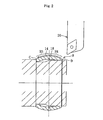
- FIGS. 1 through 3 An embodiment of a cage for a constant velocity universal joint according to the present invention is described with reference to FIGS. 1 through 3 .
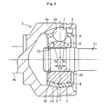
- FIG. 3 illustrates a constant velocity universal joint using the cage for a constant velocity universal joint according to the present invention.
- the constant velocity universal joint includes an outer race 3 as an outer joint member which has ball track grooves 2 (hereinafter, sometimes simply referred to as track grooves 2) formed in an inner diameter surface 1, an inner race 6 as an inner joint member which has ball track grooves 5 (hereinafter, sometimes simply referred to as track grooves 5) formed in an outer diameter surface 4, multiple balls 7 which are interposed between the track grooves 2 of the outer race 3 and the track grooves 5 of the inner race 6 so as to transmit torque, and a cage 8 which is interposed between the inner diameter surface 1 of the outer race 3 and the outer diameter surface 4 of the inner race 6 so as to hold the balls 7.
- the outer race 3 is constructed by a bowl-shape mouth portion 3a having the track grooves 2 and a stem portion 3b protruding from the bottom portion of the mouth portion 3a.
- a shaft 11 is inserted into a central hole (inner diameter hole) 12 of the inner race 6 so as to provide spline engagement therebetween, and the spline engagement enables torque transmission therebetween.
- the shaft 11 is retained with respect to the inner race 6 by a stopper ring 13.
- a center curvature 01 of the track grooves 2 of the outer race 3 is set by being shifted in the axial direction from a joint center O to the opening side of the outer race 3.
- a center curvature 02 of the track grooves 5 of the inner race 6 is set by being separated in the axial direction from the joint center O by an equal distant f to the inner side which is opposite to the center curvature 01 of the track grooves 2 of the outer race 3.
- the cage 8 includes an outer diameter surface 14 which is guided while being held in contact with the inner diameter surface 1 of the outer race 3, an inner diameter surface 15 which is guided while being held in contact with the outer diameter surface 4 of the inner race 6, and pockets 16 for accommodating the balls 7.
- the outer diameter surface 14 and the inner diameter surface 15 of the cage 8 are machined surfaces obtained after quenching. That is, in the case where the cage 8 is made of steel material such as medium carbon steel, the outer diameter surface 14 and the inner diameter surface 15 are machined after a thermal curing process (induction quenching, for example).
- the induction quenching represents quenching in which a curing process-subjected member is put between coils which carry high-frequency current so that the surface thereof is heated with Joule heat which is generated by eddy current in the surface thereof.
- the inner diameter surface 15 of the cage 8 is divided in a range H1 extending from an axial center 17 to an end A which corresponds to an opening side of the outer race 3 (hereinafter, sometimes simply referred to as end A corresponding to opening side), and in a range H2 extending from the axial center 17 to an end B which corresponds to an inner side of the outer race 3 (hereinafter, sometimes simply referred to as end B corresponding to inner side).
- the spherical surface roughnesses in H1 and H2 are different from each other.
- the spherical surface roughness in the range H1 is larger than the spherical surface roughness in the range H2.
- the surface roughness in the range H1 is R1 and the surface roughness in the range H2 is R2, R2 ⁇ R1 ⁇ 2 ⁇ R2 is established. Further, the surface roughness R2 in the range H2 is equal to or smaller than Ra: 0.8.
- the outer diameter surface 14 of the cage 8 is divided in a range H3 extending from an axial center 18 to an end C which corresponds to an inner side of the outer race 3 (hereinafter, sometimes simply referred to as end C corresponding to inner side), and in a range H4 extending from the axial center 18 to an end D which corresponds to an opening side of the outer race 3 (hereinafter, sometimes simply referred to as end D corresponding to opening side).
- the spherical surface roughnesses in H3 and H4 are different from each other.
- the spherical surface roughness in the range H3 is larger than the spherical surface roughness in the range H4.
- the surface roughness in the range H3 is R3 and the surface roughness in the range H4 is R4, R4 ⁇ R3 ⁇ 2 ⁇ R4 is established. Further, the surface roughness R4 in the range H4 is equal to or smaller than Ra: 0.8.
- the surface roughness represents center-line average roughness, which is obtained by folding back a roughness curve with reference to the center line and by representing a value which is obtained by dividing a value of the area by a measurement length with micrometer ( ⁇ m), the area being defined by the roughness curve and the center line.
- the machining (grinding) of the inner diameter surface 15 of the cage 8 is performed by moving, as indicated by an arrow, the blade of a tool 19 from the end B side which corresponds to the inner side of the inner diameter surface 15 to the end A side which corresponds to the opening side thereof.
- the surface roughness in the range H1 extending from the axial center 17 to the end A side may be larger than the surface roughness in the range H2 extending from the axial center 17 to the end B side.
- the machining (grinding) of the outer diameter surface 14 of the cage 8 is performed by moving, as indicated by an arrow, the blade of a tool 20 from the end D side which corresponds to the opening side of the outer diameter surface 14 to the end C side which corresponds to the inner side thereof.
- the surface roughness in the range H3 extending from the axial center 18 to the end C side may be larger than the surface roughness in the range H4 extending from the axial center 18 to the end D side.
- the finishing which is performed with use of the cutting tool can be roughly completed. Therefore, the abrasion of the cutting tool can be reduced. In this manner, the life of the cutting tool can be extended, which leads to reduction in manufacturing cost.
- the spherical surface roughness in the range H2 extending from the axial center 17 of the inner diameter surface 15 to the end B side which corresponds to the inner side may be larger than the spherical surface roughness in the range H1 extending from the axial center 17 to the end A side which corresponds to the opening side.
- the track grooves 2 of the outer race 3 open on the inlet side (opening side), and hence the influence on the function of the constant velocity universal joint is reduced in the case where the spherical surface roughness in the range H1 extending from the axial center 17 to the end A side which corresponds to the opening side is made larger than the spherical surface roughness in the range H2 extending from the axial center 17 to the end B side which corresponds to the inner side.
- the spherical surface roughness in the range H1 extending from the axial center 17 to the end A side be larger (than the spherical surface roughness in the range H2).
- the spherical surface roughness in the range H4 extending from the axial center 18 to the end D side which corresponds to the opening side may be larger than the spherical surface roughness in the range H3 extending from the axial center 18 to the end C side which corresponds to the inner side.
- the spherical surface roughness in the range H3 extending from the axial center 18 of the outer diameter surface 14 to the end C side which corresponds to the inner side be larger than the spherical surface roughness in the range H4 extending from the axial center 18 to the end D side which corresponds to the opening side.
- the present invention is not limited to the above-mentioned embodiment, and various modifications can be made thereto.
- the constant velocity universal joint of a Barfield type (BJ) is illustrated in FIG. 3
- constant velocity universal joints of other types such as an undercut-free type (UJ) may be used.
- the number of the balls 7 can be arbitrarily set. Specifically, while being able to be set within the range of three to eight, the number of the balls 7 is not limited thereto. Further, a curing process except the induction quenching, such as carburizing and quenching, or nitriding may be adopted.
- the spherical surface roughnesses on the end side which corresponds to the opening side and on the end side which corresponds to the inner side with respect to the axial center as a boundary line of only one of the inner diameter surface 15 and the outer diameter surface 14 of the cage 8 may be different from each other.
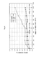
- FIG. 4 shows a relation between the number of workings of the cage inner diameter surface, which can be performed with use of one cutting tool, and the surface roughness thereof.
- • denotes a surface roughness at the axial center 17 of the inner diameter surface 15
- ⁇ denotes a surface roughness of the inner diameter surface 15 on the end B side which corresponds to the inner side
- ⁇ denotes a surface roughness of the inner diameter surface 15 on the end A side which corresponds to the inlet side (opening side).
- the life of the tool can be extended so as to increase the number of workings to one thousand, for example.
- the graph of the relation between the number of workings and the surface roughness of the outer diameter surface 14 of the cage 8 is omitted, through adoption of the structure of the present invention, the outer diameter surface 14 of the cage 8 is capable of extending the life of the tool as well as the inner diameter surface 15.
Landscapes
- Engineering & Computer Science (AREA)
- General Engineering & Computer Science (AREA)
- Mechanical Engineering (AREA)
- Rolling Contact Bearings (AREA)
Claims (8)
- Cage pour un joint universel homocinétique, comprenant :- une surface de diamètre extérieur (14) guidée par un élément de joint extérieur (3) ;- une surface de diamètre intérieur (15) guidée par un élément de joint intérieur (6) ; et- des poches (16) pour loger plusieurs billes (7) qui sont placées entre l'élément de joint extérieur (3) et l'élément de joint intérieur (6),caractérisée en ce qu'une rugosité de surface sphérique dans une zone (H1) qui s'étend d'un centre axial (17) de la surface de diamètre intérieur (15) à un côté d'extrémité (A) de la surface de diamètre intérieur (15) qui correspond à un côté d'ouverture de l'élément de joint extérieur (3) est différente d'une rugosité de surface sphérique dans une zone (H2) qui s'étend du centre axial (17) de la surface de diamètre intérieur (15) à un côté d'extrémité (B) de la surface de diamètre intérieur (15) qui correspond à un côté intérieur de l'élément de joint extérieur (3).
- Cage pour un joint universel homocinétique selon la revendication 1, étant précisé que la rugosité de surface sphérique dans la zone (H1) qui s'étend du centre axial (17) de la surface de diamètre intérieur (15) au côté d'extrémité (A) de la surface de diamètre intérieur (15) qui correspond au côté d'ouverture de l'élément de joint extérieur (3) est supérieure à la rugosité de surface sphérique dans la zone (H2) qui s'étend du centre axial (17) de la surface de diamètre intérieur (15) au côté d'extrémité (B) de la surface de diamètre intérieur (15) qui correspond au côté intérieur de l'élément de joint extérieur (3).
- Cage pour un joint universel homocinétique selon la revendication 2, étant précisé que quand la rugosité de surface sphérique dans la zone (H1) qui s'étend du centre axial (17) de la surface de diamètre intérieur (15) au côté d'extrémité (A) de la surface de diamètre intérieur (15) qui correspond au côté d'ouverture de l'élément de joint extérieur (3) est R1, et que la rugosité de surface sphérique dans la zone (H2) qui s'étend du centre axial (17) de la surface de diamètre intérieur (15) au côté d'extrémité (B) de la surface de diamètre intérieur (15) qui correspond au côté intérieur de l'élément de joint extérieur (3) est R2, R2<R1<2×R2 est établi.
- Cage pour un joint universel homocinétique selon la revendication 3, étant précisé que la rugosité de surface sphérique dans la zone (H2) qui s'étend du centre axial (17) de la surface de diamètre intérieur (15) au côté d'extrémité (B) de la surface de diamètre intérieur (15) qui correspond au côté intérieur de l'élément de joint extérieur (3) est égale ou inférieure à Ra:0,8.
- Cage pour un joint universel homocinétique, comprenant :- une surface de diamètre extérieur (14) guidée par un élément de joint extérieur (3) ;- une surface de diamètre intérieur (15) guidée par un élément de joint intérieur (6) ; et- des poches (16) pour loger plusieurs billes (7) qui sont placées entre l'élément de joint extérieur (3) et l'élément de joint intérieur (6),caractérisée en ce qu'une rugosité de surface sphérique dans une zone (H3) qui s'étend d'un centre axial (18) de la surface de diamètre extérieur (14) à un côté d'extrémité (C) de la surface de diamètre extérieur (14) qui correspond à un côté intérieur de l'élément de joint extérieur (3) est différente d'une rugosité de surface sphérique dans une zone (H4) qui s'étend du centre axial (18) de la surface de diamètre extérieur (14) à un côté d'extrémité (D) de la surface de diamètre extérieur (14) qui correspond à un côté d'ouverture de l'élément de joint extérieur (3).
- Cage pour un joint universel homocinétique selon la revendication 5, étant précisé que la rugosité de surface sphérique dans la zone (H3) qui s'étend du centre axial (18) de la surface de diamètre extérieur (14) au côté d'extrémité (C) de la surface de diamètre extérieur (14) qui correspond au côté intérieur de l'élément de joint extérieur (3) est supérieure à la rugosité de surface sphérique dans la zone (H4) qui s'étend du centre axial (18) de la surface de diamètre extérieur (14) au côté d'extrémité (D) de la surface de diamètre extérieur (14) qui correspond au côté d'ouverture de l'élément de joint extérieur (3).
- Cage pour un joint universel homocinétique selon la revendication 6, étant précisé que quand la rugosité de surface sphérique dans la zone (H3) qui s'étend du centre axial (18) de la surface de diamètre extérieur (14) au côté d'extrémité (C) de la surface de diamètre extérieur (14) qui correspond au côté intérieur de l'élément de joint extérieur (3) est R3, et que la rugosité de surface sphérique dans la zone (H4) qui s'étend du centre axial (18) de la surface de diamètre extérieur (14) au côté d'extrémité (D) de la surface de diamètre extérieur (14) qui correspond au côté d'ouverture de l'élément de joint extérieur (3) est R4, R4<R3<2xR4 est établi.
- Cage pour un joint universel homocinétique selon la revendication 7, étant précisé que la rugosité de surface sphérique dans la zone (H4) qui s'étend du centre axial (18) de la surface de diamètre extérieur (14) au côté d'extrémité (D) de la surface de diamètre extérieur (14) qui correspond au côté d'ouverture de l'élément de joint extérieur (3) est égale ou inférieure à Ra:0,8.
Applications Claiming Priority (2)
| Application Number | Priority Date | Filing Date | Title |
|---|---|---|---|
| JP2008019491A JP5202974B2 (ja) | 2008-01-30 | 2008-01-30 | 等速自在継手用ケージ |
| PCT/JP2009/050001 WO2009096200A1 (fr) | 2008-01-30 | 2009-01-05 | Cage pour joint universel homocinétique |
Publications (3)
| Publication Number | Publication Date |
|---|---|
| EP2246583A1 EP2246583A1 (fr) | 2010-11-03 |
| EP2246583A4 EP2246583A4 (fr) | 2012-05-09 |
| EP2246583B1 true EP2246583B1 (fr) | 2013-05-22 |
Family
ID=40912553
Family Applications (1)
| Application Number | Title | Priority Date | Filing Date |
|---|---|---|---|
| EP09705154.4A Not-in-force EP2246583B1 (fr) | 2008-01-30 | 2009-01-05 | Cage pour joint universel homocinétique |
Country Status (5)
| Country | Link |
|---|---|
| US (1) | US8313387B2 (fr) |
| EP (1) | EP2246583B1 (fr) |
| JP (1) | JP5202974B2 (fr) |
| CN (1) | CN101918727B (fr) |
| WO (1) | WO2009096200A1 (fr) |
Family Cites Families (7)
| Publication number | Priority date | Publication date | Assignee | Title |
|---|---|---|---|---|
| US4834400A (en) * | 1988-03-15 | 1989-05-30 | University Of New Mexico | Differential surface roughness dynamic seals and bearings |
| US4973068A (en) * | 1988-03-15 | 1990-11-27 | University Of New Mexico | Differential surface roughness dynamic seals and bearings |
| JPH07310752A (ja) * | 1994-05-13 | 1995-11-28 | Toyota Motor Corp | 等速自在継手の内輪およびその製造方法 |
| US5586826A (en) * | 1994-12-19 | 1996-12-24 | Skf Sverige Ab | Roller bearing provided with roller skew control and long life characteristics |
| JP2002188653A (ja) * | 2000-12-20 | 2002-07-05 | Ntn Corp | 等速自在継手 |
| JP4813062B2 (ja) * | 2005-02-04 | 2011-11-09 | Ntn株式会社 | 摺動式等速自在継手 |
| JP2007232033A (ja) * | 2006-02-28 | 2007-09-13 | Ntn Corp | 固定式等速自在継手及びその製造方法 |
-
2008
- 2008-01-30 JP JP2008019491A patent/JP5202974B2/ja not_active Expired - Fee Related
-
2009
- 2009-01-05 CN CN2009801024496A patent/CN101918727B/zh not_active Expired - Fee Related
- 2009-01-05 WO PCT/JP2009/050001 patent/WO2009096200A1/fr not_active Ceased
- 2009-01-05 US US12/864,732 patent/US8313387B2/en not_active Expired - Fee Related
- 2009-01-05 EP EP09705154.4A patent/EP2246583B1/fr not_active Not-in-force
Also Published As
| Publication number | Publication date |
|---|---|
| US20110045914A1 (en) | 2011-02-24 |
| WO2009096200A1 (fr) | 2009-08-06 |
| CN101918727B (zh) | 2013-03-06 |
| JP5202974B2 (ja) | 2013-06-05 |
| JP2009180285A (ja) | 2009-08-13 |
| EP2246583A1 (fr) | 2010-11-03 |
| EP2246583A4 (fr) | 2012-05-09 |
| CN101918727A (zh) | 2010-12-15 |
| US8313387B2 (en) | 2012-11-20 |
Similar Documents
| Publication | Publication Date | Title |
|---|---|---|
| US7094155B2 (en) | Constant velocity universal joint | |
| US6506121B2 (en) | Cage for constant-velocity joint and method for manufacturing the same | |
| EP2284411B1 (fr) | Joint homocinétique de type fixe | |
| EP2881605A1 (fr) | Élément de retenue pour joint homocinétique, joint homcinétique fixe comprenant celui-ci et arbre d'entraînement comprenant ledit joint homocinétique fixe | |
| EP2251559B1 (fr) | Élément intérieur de joint pour joint universel homocinétique, procédé de production correspondant, et joint universel homocinétique | |
| EP2505863A1 (fr) | Joint homocinétique fixe | |
| EP3904716B1 (fr) | Accouplement homocinétique du type tripode | |
| CN1834490B (zh) | 固定等速万向节 | |
| JP2009121673A (ja) | 等速自在継手 | |
| EP2154389B1 (fr) | Joint homocinétique fixe et procédé de production de la bague extérieure du joint | |
| EP2246583B1 (fr) | Cage pour joint universel homocinétique | |
| EP2749783B1 (fr) | Joint homocinétique et son procédé de fabrication | |
| JP2010043691A (ja) | 等速自在継手およびその製造方法 | |
| JP2009228813A (ja) | 等速自在継手 | |
| JP4813286B2 (ja) | 等速自在継手用外側継手部材 | |
| JP2009275878A (ja) | スプライン軸、動力伝達シャフトおよび等速自在継手外輪 | |
| CN116724178B (zh) | 反向轨道万向节和用于制造反向轨道万向节的方法 | |
| JP2011208674A (ja) | 等速自在継手 | |
| JPH11294476A (ja) | 等速自在継手 | |
| JP2009228811A (ja) | 等速自在継手 | |
| JP2009228809A (ja) | 等速自在継手 | |
| WO2007125844A1 (fr) | Joint universel homocinétique | |
| JP2009185878A (ja) | 等速自在継手及びシャフトアッセンブリ | |
| JP2009228810A (ja) | 等速自在継手 | |
| JP2008304006A (ja) | 固定式等速自在継手およびその外輪の製造方法 |
Legal Events
| Date | Code | Title | Description |
|---|---|---|---|
| PUAI | Public reference made under article 153(3) epc to a published international application that has entered the european phase |
Free format text: ORIGINAL CODE: 0009012 |
|
| 17P | Request for examination filed |
Effective date: 20100826 |
|
| AK | Designated contracting states |
Kind code of ref document: A1 Designated state(s): AT BE BG CH CY CZ DE DK EE ES FI FR GB GR HR HU IE IS IT LI LT LU LV MC MK MT NL NO PL PT RO SE SI SK TR |
|
| AX | Request for extension of the european patent |
Extension state: AL BA RS |
|
| DAX | Request for extension of the european patent (deleted) | ||
| A4 | Supplementary search report drawn up and despatched |
Effective date: 20120411 |
|
| RIC1 | Information provided on ipc code assigned before grant |
Ipc: F16D 3/223 20110101ALI20120403BHEP Ipc: F16D 3/20 20060101AFI20120403BHEP |
|
| GRAP | Despatch of communication of intention to grant a patent |
Free format text: ORIGINAL CODE: EPIDOSNIGR1 |
|
| RIC1 | Information provided on ipc code assigned before grant |
Ipc: F16D 3/223 20110101ALI20121109BHEP Ipc: F16D 3/20 20060101AFI20121109BHEP |
|
| GRAS | Grant fee paid |
Free format text: ORIGINAL CODE: EPIDOSNIGR3 |
|
| GRAA | (expected) grant |
Free format text: ORIGINAL CODE: 0009210 |
|
| AK | Designated contracting states |
Kind code of ref document: B1 Designated state(s): AT BE BG CH CY CZ DE DK EE ES FI FR GB GR HR HU IE IS IT LI LT LU LV MC MK MT NL NO PL PT RO SE SI SK TR |
|
| REG | Reference to a national code |
Ref country code: GB Ref legal event code: FG4D |
|
| REG | Reference to a national code |
Ref country code: CH Ref legal event code: EP |
|
| REG | Reference to a national code |
Ref country code: AT Ref legal event code: REF Ref document number: 613390 Country of ref document: AT Kind code of ref document: T Effective date: 20130615 |
|
| REG | Reference to a national code |
Ref country code: IE Ref legal event code: FG4D |
|
| REG | Reference to a national code |
Ref country code: DE Ref legal event code: R096 Ref document number: 602009015870 Country of ref document: DE Effective date: 20130718 |
|
| REG | Reference to a national code |
Ref country code: AT Ref legal event code: MK05 Ref document number: 613390 Country of ref document: AT Kind code of ref document: T Effective date: 20130522 |
|
| REG | Reference to a national code |
Ref country code: LT Ref legal event code: MG4D |
|
| PG25 | Lapsed in a contracting state [announced via postgrant information from national office to epo] |
Ref country code: IS Free format text: LAPSE BECAUSE OF FAILURE TO SUBMIT A TRANSLATION OF THE DESCRIPTION OR TO PAY THE FEE WITHIN THE PRESCRIBED TIME-LIMIT Effective date: 20130922 Ref country code: NO Free format text: LAPSE BECAUSE OF FAILURE TO SUBMIT A TRANSLATION OF THE DESCRIPTION OR TO PAY THE FEE WITHIN THE PRESCRIBED TIME-LIMIT Effective date: 20130822 Ref country code: ES Free format text: LAPSE BECAUSE OF FAILURE TO SUBMIT A TRANSLATION OF THE DESCRIPTION OR TO PAY THE FEE WITHIN THE PRESCRIBED TIME-LIMIT Effective date: 20130902 Ref country code: SE Free format text: LAPSE BECAUSE OF FAILURE TO SUBMIT A TRANSLATION OF THE DESCRIPTION OR TO PAY THE FEE WITHIN THE PRESCRIBED TIME-LIMIT Effective date: 20130522 Ref country code: FI Free format text: LAPSE BECAUSE OF FAILURE TO SUBMIT A TRANSLATION OF THE DESCRIPTION OR TO PAY THE FEE WITHIN THE PRESCRIBED TIME-LIMIT Effective date: 20130522 Ref country code: GR Free format text: LAPSE BECAUSE OF FAILURE TO SUBMIT A TRANSLATION OF THE DESCRIPTION OR TO PAY THE FEE WITHIN THE PRESCRIBED TIME-LIMIT Effective date: 20130823 Ref country code: PT Free format text: LAPSE BECAUSE OF FAILURE TO SUBMIT A TRANSLATION OF THE DESCRIPTION OR TO PAY THE FEE WITHIN THE PRESCRIBED TIME-LIMIT Effective date: 20130923 Ref country code: LT Free format text: LAPSE BECAUSE OF FAILURE TO SUBMIT A TRANSLATION OF THE DESCRIPTION OR TO PAY THE FEE WITHIN THE PRESCRIBED TIME-LIMIT Effective date: 20130522 Ref country code: AT Free format text: LAPSE BECAUSE OF FAILURE TO SUBMIT A TRANSLATION OF THE DESCRIPTION OR TO PAY THE FEE WITHIN THE PRESCRIBED TIME-LIMIT Effective date: 20130522 Ref country code: SI Free format text: LAPSE BECAUSE OF FAILURE TO SUBMIT A TRANSLATION OF THE DESCRIPTION OR TO PAY THE FEE WITHIN THE PRESCRIBED TIME-LIMIT Effective date: 20130522 |
|
| REG | Reference to a national code |
Ref country code: NL Ref legal event code: VDEP Effective date: 20130522 |
|
| PG25 | Lapsed in a contracting state [announced via postgrant information from national office to epo] |
Ref country code: PL Free format text: LAPSE BECAUSE OF FAILURE TO SUBMIT A TRANSLATION OF THE DESCRIPTION OR TO PAY THE FEE WITHIN THE PRESCRIBED TIME-LIMIT Effective date: 20130522 Ref country code: BG Free format text: LAPSE BECAUSE OF FAILURE TO SUBMIT A TRANSLATION OF THE DESCRIPTION OR TO PAY THE FEE WITHIN THE PRESCRIBED TIME-LIMIT Effective date: 20130822 Ref country code: HR Free format text: LAPSE BECAUSE OF FAILURE TO SUBMIT A TRANSLATION OF THE DESCRIPTION OR TO PAY THE FEE WITHIN THE PRESCRIBED TIME-LIMIT Effective date: 20130522 |
|
| PG25 | Lapsed in a contracting state [announced via postgrant information from national office to epo] |
Ref country code: LV Free format text: LAPSE BECAUSE OF FAILURE TO SUBMIT A TRANSLATION OF THE DESCRIPTION OR TO PAY THE FEE WITHIN THE PRESCRIBED TIME-LIMIT Effective date: 20130522 |
|
| PG25 | Lapsed in a contracting state [announced via postgrant information from national office to epo] |
Ref country code: CZ Free format text: LAPSE BECAUSE OF FAILURE TO SUBMIT A TRANSLATION OF THE DESCRIPTION OR TO PAY THE FEE WITHIN THE PRESCRIBED TIME-LIMIT Effective date: 20130522 Ref country code: BE Free format text: LAPSE BECAUSE OF FAILURE TO SUBMIT A TRANSLATION OF THE DESCRIPTION OR TO PAY THE FEE WITHIN THE PRESCRIBED TIME-LIMIT Effective date: 20130522 Ref country code: EE Free format text: LAPSE BECAUSE OF FAILURE TO SUBMIT A TRANSLATION OF THE DESCRIPTION OR TO PAY THE FEE WITHIN THE PRESCRIBED TIME-LIMIT Effective date: 20130522 Ref country code: DK Free format text: LAPSE BECAUSE OF FAILURE TO SUBMIT A TRANSLATION OF THE DESCRIPTION OR TO PAY THE FEE WITHIN THE PRESCRIBED TIME-LIMIT Effective date: 20130522 Ref country code: SK Free format text: LAPSE BECAUSE OF FAILURE TO SUBMIT A TRANSLATION OF THE DESCRIPTION OR TO PAY THE FEE WITHIN THE PRESCRIBED TIME-LIMIT Effective date: 20130522 |
|
| PG25 | Lapsed in a contracting state [announced via postgrant information from national office to epo] |
Ref country code: IT Free format text: LAPSE BECAUSE OF FAILURE TO SUBMIT A TRANSLATION OF THE DESCRIPTION OR TO PAY THE FEE WITHIN THE PRESCRIBED TIME-LIMIT Effective date: 20130522 Ref country code: NL Free format text: LAPSE BECAUSE OF FAILURE TO SUBMIT A TRANSLATION OF THE DESCRIPTION OR TO PAY THE FEE WITHIN THE PRESCRIBED TIME-LIMIT Effective date: 20130522 Ref country code: RO Free format text: LAPSE BECAUSE OF FAILURE TO SUBMIT A TRANSLATION OF THE DESCRIPTION OR TO PAY THE FEE WITHIN THE PRESCRIBED TIME-LIMIT Effective date: 20130522 |
|
| PLBE | No opposition filed within time limit |
Free format text: ORIGINAL CODE: 0009261 |
|
| STAA | Information on the status of an ep patent application or granted ep patent |
Free format text: STATUS: NO OPPOSITION FILED WITHIN TIME LIMIT |
|
| 26N | No opposition filed |
Effective date: 20140225 |
|
| REG | Reference to a national code |
Ref country code: DE Ref legal event code: R097 Ref document number: 602009015870 Country of ref document: DE Effective date: 20140225 |
|
| PG25 | Lapsed in a contracting state [announced via postgrant information from national office to epo] |
Ref country code: MC Free format text: LAPSE BECAUSE OF FAILURE TO SUBMIT A TRANSLATION OF THE DESCRIPTION OR TO PAY THE FEE WITHIN THE PRESCRIBED TIME-LIMIT Effective date: 20130522 Ref country code: LU Free format text: LAPSE BECAUSE OF FAILURE TO SUBMIT A TRANSLATION OF THE DESCRIPTION OR TO PAY THE FEE WITHIN THE PRESCRIBED TIME-LIMIT Effective date: 20140105 |
|
| REG | Reference to a national code |
Ref country code: CH Ref legal event code: PL |
|
| GBPC | Gb: european patent ceased through non-payment of renewal fee |
Effective date: 20140105 |
|
| PG25 | Lapsed in a contracting state [announced via postgrant information from national office to epo] |
Ref country code: LI Free format text: LAPSE BECAUSE OF NON-PAYMENT OF DUE FEES Effective date: 20140131 Ref country code: CH Free format text: LAPSE BECAUSE OF NON-PAYMENT OF DUE FEES Effective date: 20140131 |
|
| REG | Reference to a national code |
Ref country code: IE Ref legal event code: MM4A |
|
| PG25 | Lapsed in a contracting state [announced via postgrant information from national office to epo] |
Ref country code: GB Free format text: LAPSE BECAUSE OF NON-PAYMENT OF DUE FEES Effective date: 20140105 |
|
| PG25 | Lapsed in a contracting state [announced via postgrant information from national office to epo] |
Ref country code: IE Free format text: LAPSE BECAUSE OF NON-PAYMENT OF DUE FEES Effective date: 20140105 |
|
| REG | Reference to a national code |
Ref country code: FR Ref legal event code: PLFP Year of fee payment: 8 |
|
| PG25 | Lapsed in a contracting state [announced via postgrant information from national office to epo] |
Ref country code: MT Free format text: LAPSE BECAUSE OF FAILURE TO SUBMIT A TRANSLATION OF THE DESCRIPTION OR TO PAY THE FEE WITHIN THE PRESCRIBED TIME-LIMIT Effective date: 20130522 |
|
| PGFP | Annual fee paid to national office [announced via postgrant information from national office to epo] |
Ref country code: FR Payment date: 20151208 Year of fee payment: 8 |
|
| PGFP | Annual fee paid to national office [announced via postgrant information from national office to epo] |
Ref country code: DE Payment date: 20151229 Year of fee payment: 8 |
|
| PG25 | Lapsed in a contracting state [announced via postgrant information from national office to epo] |
Ref country code: CY Free format text: LAPSE BECAUSE OF FAILURE TO SUBMIT A TRANSLATION OF THE DESCRIPTION OR TO PAY THE FEE WITHIN THE PRESCRIBED TIME-LIMIT Effective date: 20130522 |
|
| PG25 | Lapsed in a contracting state [announced via postgrant information from national office to epo] |
Ref country code: HU Free format text: LAPSE BECAUSE OF FAILURE TO SUBMIT A TRANSLATION OF THE DESCRIPTION OR TO PAY THE FEE WITHIN THE PRESCRIBED TIME-LIMIT; INVALID AB INITIO Effective date: 20090105 Ref country code: TR Free format text: LAPSE BECAUSE OF FAILURE TO SUBMIT A TRANSLATION OF THE DESCRIPTION OR TO PAY THE FEE WITHIN THE PRESCRIBED TIME-LIMIT Effective date: 20130522 |
|
| REG | Reference to a national code |
Ref country code: DE Ref legal event code: R119 Ref document number: 602009015870 Country of ref document: DE |
|
| REG | Reference to a national code |
Ref country code: FR Ref legal event code: ST Effective date: 20170929 |
|
| PG25 | Lapsed in a contracting state [announced via postgrant information from national office to epo] |
Ref country code: FR Free format text: LAPSE BECAUSE OF NON-PAYMENT OF DUE FEES Effective date: 20170131 |
|
| PG25 | Lapsed in a contracting state [announced via postgrant information from national office to epo] |
Ref country code: DE Free format text: LAPSE BECAUSE OF NON-PAYMENT OF DUE FEES Effective date: 20170801 |
|
| PG25 | Lapsed in a contracting state [announced via postgrant information from national office to epo] |
Ref country code: MK Free format text: LAPSE BECAUSE OF FAILURE TO SUBMIT A TRANSLATION OF THE DESCRIPTION OR TO PAY THE FEE WITHIN THE PRESCRIBED TIME-LIMIT Effective date: 20130522 |