EP2246647B1 - Sonde d'échauffement de la terre - Google Patents
Sonde d'échauffement de la terre Download PDFInfo
- Publication number
- EP2246647B1 EP2246647B1 EP10004479.1A EP10004479A EP2246647B1 EP 2246647 B1 EP2246647 B1 EP 2246647B1 EP 10004479 A EP10004479 A EP 10004479A EP 2246647 B1 EP2246647 B1 EP 2246647B1
- Authority
- EP
- European Patent Office
- Prior art keywords
- pipe
- heat exchanger
- flow pipe
- flow
- probe according
- Prior art date
- Legal status (The legal status is an assumption and is not a legal conclusion. Google has not performed a legal analysis and makes no representation as to the accuracy of the status listed.)
- Active
Links
- 239000000523 sample Substances 0.000 title claims description 72
- 238000009413 insulation Methods 0.000 claims description 17
- 230000008878 coupling Effects 0.000 claims description 13
- 238000010168 coupling process Methods 0.000 claims description 13
- 238000005859 coupling reaction Methods 0.000 claims description 13
- 238000010438 heat treatment Methods 0.000 claims description 13
- 239000000463 material Substances 0.000 claims description 7
- 238000007789 sealing Methods 0.000 claims description 5
- 229910001220 stainless steel Inorganic materials 0.000 claims description 5
- 239000010935 stainless steel Substances 0.000 claims description 5
- XLYOFNOQVPJJNP-UHFFFAOYSA-N water Substances O XLYOFNOQVPJJNP-UHFFFAOYSA-N 0.000 claims description 4
- 238000003466 welding Methods 0.000 claims description 4
- 238000004804 winding Methods 0.000 claims description 4
- 238000009835 boiling Methods 0.000 claims description 3
- 238000006073 displacement reaction Methods 0.000 claims description 2
- 239000002984 plastic foam Substances 0.000 claims description 2
- 238000000034 method Methods 0.000 claims 2
- 239000003795 chemical substances by application Substances 0.000 claims 1
- 230000002349 favourable effect Effects 0.000 claims 1
- 239000012858 resilient material Substances 0.000 claims 1
- 230000008093 supporting effect Effects 0.000 claims 1
- 239000002689 soil Substances 0.000 description 6
- 150000001875 compounds Chemical class 0.000 description 4
- 238000001816 cooling Methods 0.000 description 3
- 239000004033 plastic Substances 0.000 description 3
- 239000000126 substance Substances 0.000 description 3
- OKTJSMMVPCPJKN-UHFFFAOYSA-N Carbon Chemical compound [C] OKTJSMMVPCPJKN-UHFFFAOYSA-N 0.000 description 2
- 229910000639 Spring steel Inorganic materials 0.000 description 2
- 230000008901 benefit Effects 0.000 description 2
- 230000000694 effects Effects 0.000 description 2
- 125000006850 spacer group Chemical group 0.000 description 2
- VYPSYNLAJGMNEJ-UHFFFAOYSA-N Silicium dioxide Chemical compound O=[Si]=O VYPSYNLAJGMNEJ-UHFFFAOYSA-N 0.000 description 1
- 239000004809 Teflon Substances 0.000 description 1
- 229920006362 Teflon® Polymers 0.000 description 1
- 239000002250 absorbent Substances 0.000 description 1
- 230000002745 absorbent Effects 0.000 description 1
- 230000004323 axial length Effects 0.000 description 1
- 230000005540 biological transmission Effects 0.000 description 1
- 238000004891 communication Methods 0.000 description 1
- 239000002131 composite material Substances 0.000 description 1
- 238000006880 cross-coupling reaction Methods 0.000 description 1
- 238000007599 discharging Methods 0.000 description 1
- 239000013013 elastic material Substances 0.000 description 1
- 239000013529 heat transfer fluid Substances 0.000 description 1
- 238000009434 installation Methods 0.000 description 1
- 238000002955 isolation Methods 0.000 description 1
- 238000004519 manufacturing process Methods 0.000 description 1
- 239000002994 raw material Substances 0.000 description 1
- 238000000926 separation method Methods 0.000 description 1
- 238000001179 sorption measurement Methods 0.000 description 1
- 230000035882 stress Effects 0.000 description 1
- 239000002352 surface water Substances 0.000 description 1
- 239000000725 suspension Substances 0.000 description 1
- 230000008646 thermal stress Effects 0.000 description 1
- 230000007704 transition Effects 0.000 description 1
Images


Classifications
-
- F—MECHANICAL ENGINEERING; LIGHTING; HEATING; WEAPONS; BLASTING
- F24—HEATING; RANGES; VENTILATING
- F24T—GEOTHERMAL COLLECTORS; GEOTHERMAL SYSTEMS
- F24T10/00—Geothermal collectors
- F24T10/10—Geothermal collectors with circulation of working fluids through underground channels, the working fluids not coming into direct contact with the ground
- F24T10/13—Geothermal collectors with circulation of working fluids through underground channels, the working fluids not coming into direct contact with the ground using tube assemblies suitable for insertion into boreholes in the ground, e.g. geothermal probes
-
- Y—GENERAL TAGGING OF NEW TECHNOLOGICAL DEVELOPMENTS; GENERAL TAGGING OF CROSS-SECTIONAL TECHNOLOGIES SPANNING OVER SEVERAL SECTIONS OF THE IPC; TECHNICAL SUBJECTS COVERED BY FORMER USPC CROSS-REFERENCE ART COLLECTIONS [XRACs] AND DIGESTS
- Y02—TECHNOLOGIES OR APPLICATIONS FOR MITIGATION OR ADAPTATION AGAINST CLIMATE CHANGE
- Y02E—REDUCTION OF GREENHOUSE GAS [GHG] EMISSIONS, RELATED TO ENERGY GENERATION, TRANSMISSION OR DISTRIBUTION
- Y02E10/00—Energy generation through renewable energy sources
- Y02E10/10—Geothermal energy
Definitions
- the invention relates to a geothermal probe, preferably made of stainless steel, with an outer heat exchanger tube, with an inner, coaxial heat exchanger tube to the flow tube in the region of a probe foot with the annular channel between the heat exchanger tube and flow tube in flow communication and with a probe head for feeding and discharging one of the flow tube and the annular channel between the flow tube and heat exchanger tube in opposite directions flowing through the heat carrier.
- a geothermal probe is known ( AT 505 457 A1 ), which comprises an outer heat exchanger tube and an inner, coaxial to the heat exchanger tube flow tube, which is flow-connected in the region of the lower probe foot with the resultant between the heat exchanger tube and the flow channel annular channel, so that, for example, a supplied via a probe head heat transfer medium first through the inner flow tube is passed to the probe foot before it flows in opposite directions through the annular channel between the flow tube and the heat exchanger tube while receiving geothermal heat through the heat exchanger tube.
- a heat carrier guide which prevents in contrast to geothermal probes with a U-shaped pipe for the heat transfer an immediate heat transfer from the ground to the inflowing in the heating mode through the inner flow tube heat transfer medium.
- the efficiency thus achieved is low, especially at comparatively low temperature differences between the supply and the outflowing heat transfer medium.
- the US 5 816 314 A discloses with, for example, the Figures 2 . 3 or 4 a helical tube through which a flow medium flows.
- this tube may have a vacuum insulation.
- the tube is rigid, whereby it can not compensate for different thermal expansions.
- the invention is therefore the object of a geothermal probe of the type described in such a way that the efficiency is significantly increased and the different temperature loads are compensated with respect to the lateral surfaces.
- the invention solves this problem by the technical teaching of claim 1 and claim 14.
- the invention is based on the finding that in conventional geothermal probes, the inner flow tube a countercurrent heat exchanger between the two heat carrier flows on the one hand through the flow tube and on the other hand through the annular channel between the outer heat exchanger tube and the flow tube, so that is heated in the heating operation by the inner flow tube aufaufende heat transfer medium with the effect that the temperature difference between the heat transfer in the heat exchanger tube to be heated and the soil gets smaller.
- the heat transfer efficiency can be increased if the greatest possible temperature difference is provided between the heat exchanging media in that the heat exchange between the opposing heat carrier flows over the inner flow tube is largely prevented by a corresponding thermal insulation of this flow tube.
- the thermal separation of the incoming and outgoing heat transfer flows makes itself of course not only in the heating mode, but also in the cooling mode noticeable, in which heat is released to the soil via the heat transfer medium through the outer heat exchanger tube to withdraw the cooled heat transfer fluid via the inner flow tube ,
- the double jacket of the flow tube can be made of a stainless steel, while the heat exchanger tube has a plastic jacket, basalt mantel or other materials.
- the flow tube can pass through the probe head connected displaceably to the heat exchanger tube in an axially displaceable manner, so that a length compensation at different thermal expansions is ensured due to the possibility of an axial relative movement between heat exchanger tube and flow tube.
- the flow tube can be composed of individual each provided with a thermal insulation pipe socket coupling sleeves.
- the connection of these individual pipe sockets with the help of the ends of the pipe socket cross-coupling sleeves is especially made on site without effort when the inner shell of the evacuated double jacket of the pipe socket projects axially beyond the outer shell and when the protruding inner shells of the pipe sockets are connected to each other via the coupling sleeves, so that when connecting the pipe socket of the evacuated double jacket is outside the connection. Since the coupling sleeve itself can provide thermal insulation, the axial interruption of the vacuum insulation in the joint area of the pipe socket is not significant.
- the evacuated intermediate space of the double jacket of the flow tube can have an absorbent, for example kieselguhr or activated carbon.
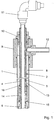
- the geothermal probe according to the illustrated embodiment has an outer heat exchanger tube 1, which receives a coaxial, inner flow tube 2.
- This inner flow tube 2 is composed of individual pipe sockets, each having an evacuated double jacket of a flow-guiding inner shell 3 and an outer shell 4.
- the individual pipe sockets are connected to each other via coupling sleeves 5, in which the over the outer jacket 4 protruding ends of the inner shell 3 are welded tight.
- the composite of the individual pipe stub flow tube 2 rests load-bearing on a probe foot 6, in the region of a flow connection 7 between the coaxial.
- Flow tube 2 and the Ring channel 8 is provided, which results between the outer heat exchanger tube 1 and the inner flow tube 2.
- a probe head 9 is provided, which passes through the flow tube 2 in a sleeve 10 axially displaceable, so that the protruding over the probe head 9 end of the flow tube 2 can be provided with a corresponding connection 11 for a heat transfer medium.
- the connection of the ring channel 8 is ensured by a connecting piece 12 in the probe head 9. For a heating operation, therefore, a heat transfer medium via the connection 11 through the heat exchanger tube 2 to the probe foot 6 ( Fig. 2 ) to then exit via the flow connection 7 in the annular channel 8 between the heat exchanger tube 1 and the flow tube 2.
- the heat transfer medium in the annular channel 8 in the heat exchanger tube 1 flows upwards, it takes on the heat exchanger tube 1 geothermal and therefore can be supplied via the connecting piece 12, for example, a heat pump.
- the warm heat transfer medium is guided in opposite directions to the heating operation and flows via the connecting piece 12 into the annular channel 8 in order to release its heat via the heat exchanger tube 1 to the surrounding soil.
- the cooled heat transfer medium is then conducted via the flow connection 7 into the flow tube 2 and can be withdrawn via the connection 11 of the flow tube 2.
- the flow tube 2 is provided with heat insulation in the form of an evacuated double jacket.
- different thermal expansion caused by them be compensated can, one end 13 of the outer shell 4 of the flow tube 2 and the individual pipe socket relative to the inner shell 3 is supported axially displaceable.
- the relative displacement between the heat exchanger tube 1 and the flow tube 2 is achieved by the displaceable guide of the flow tube 2 in the socket 10 of the probe head 9, wherein the outer sheath 4 extends beyond the bushing 10 to a heat transfer between the guided through the flow tube 1 heat transfer stream and to prevent the heat carrier flow through the probe head 9.
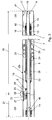
- FIG. 3 a heat exchanger tube 1 is shown, which consists of two interconnected modules 20, 21.
- One module is the end module 20, which forms the lowermost part of the heat exchanger tube 1, while a plurality of sealingly adjoining further modules 21 are connected thereto.
- connection between the individual modules 20, 21 and all other modules 21 is characterized by an inner and outer sealing connection.
- the outer connection between the heat exchanger tube 1 of the one module 20 and the adjoining heat exchanger tube 1 of the adjoining module 21 preferably consists of a sealing plug-in connection 22, wherein on one pipe wall a plug-in opening and on the other opposite pipe wall, a plug is arranged.
- the inner flow tube 2 which is designed as Doppelmaritel coaxial tube is connected to a coupling sleeve 5, which forms a screw 23, which is preferably designed as Ermeto connection for high pressures.
- the expansion ring 27, 28 formed in the filling chamber 29 and holds the area covered by the respective expansion ring 27, 28 on the outer circumference of the heat exchanger tube 1 free, so that the connector 22 in the axial expansion of the heat exchanger tube 1 in the direction of arrows 30 in the can move in from the expansion rings 27, 28 covered space.
- FIG. 3 Another feature shows the FIG. 3 in that so-called centering springs 24 in the annular channel 8 are arranged in the heat exchanger tube 1 for centering the flow tube 2 in the form of a double-jacket coaxial tube.
- the annular channel is formed by the inner circumference of the heat exchanger tube 1 and the outer circumference of the flow tube 2.
- centering springs 24 are preferably formed as oval springs. These are spring steel elements which have a round wire cross-section, but which form quasi-oval spring coils, each spring coil is offset to the adjacent spring coil by 45 ° on the circumference, so as to achieve a uniform point-like support effect on the interior and so the Flow tube 2 with as streamlined centering springs 24 safely center.
- a vacuum chamber 26 is provided, which is arranged in the region of the flow tube 2, in the space between the inner shell 3 and the outer shell 4.
- a vacuum chamber 26 is present in all modules and should provide optimal isolation of the double-jacket coaxial tube (flow tube 2) in the direction of the annular channel 8 of the heat exchanger tube 1.
- the vacuum chamber 26 extends from a fitting ring 19, starting axially downward through a cover 16 and also passing through the heat expansion bellows 14 to a cover 15, so that the bellows 14 is penetrated by the vacuum space 26.
- FIG. 4 shows a cross section through the flow tube 2 in the region of the Evakuianssrschreibchens (vacuum space 26). Between outer jacket 4 and inner jacket 3 of the flow tube 2 are again, based on the FIG. 3 , a number of the mentioned centering springs 25 are arranged.
- centering springs should result in a centering of the inner shell 3 to the outer shell 4 according to the above description.
- these are spring steel elements, which are designed as a wire round cross-section with oval spring spring windings, as described above with reference to the centering spring 24.
- centering spring 25 instead of the centering spring 25 shown here, of course, other centering are possible, such as spacer centering rings Stainless steel or Teflon, wherein the rings have radially projecting projections, or curved corrugated spring portions which are resiliently supported between the inner shell 3 and the outer shell 4.
- the production of the vacuum is based on the FIG. 4 explained in more detail.
- FIG. 4 It is shown that the vacuum is already introduced into the vacuum chamber 26, because the closures 34 are already attached to the corresponding pipe stub 31.
- a pipe connection 32 made of stainless steel is attached in a sealing manner to both pipe stubs 31, to which a vacuum is applied.
- the vacuum is generated by a vacuum pump. It was a vacuum of x * 10 -4 mbar generated, which is in principle a high vacuum.
- the pipe diameter of the pipe stub 31 determines the height of the achievable vacuum.
- the diameter has been chosen 8 mm, and the pipe stub has a corresponding height.
- the shutters 34 are manufactured by welding under vacuum and the pipe connections 32 are separated.
- a heating system By a resistance heating, a heating system is put into operation, which heats the flow tube 2, consisting of outer shell 4 and inner shell 3, which form the annular cavity of the flow tube 2 to above the boiling point of water and thereby removes trapped in the microscopically fissured surface water molecules and also other volatile substances, so that a much better vacuum quality can be achieved.
- the vacuum can also be generated faster because just the substances preventing the vacuum or harmful to the vacuum are removed by heating to above the boiling point of water.
- FIG. 5 shows as an alternative to the support of the flow tube 2 in the heat exchanger tube 1, a so-called hanging arrangement, which means that the flow tube 2 is arranged in the arranged above the ground probe head 9 hanging.
- a retaining bushing 35 is mounted on the uppermost flow tube 2, which is supported with respect to the probe head 9 with a snap ring 36.
- the probe head 9 radially inwardly on a run-on slope 39, and when the flow tube 2 is inserted from above into the probe head 9, the snap ring 36 snaps into the associated groove on the inner circumference of the probe head 9 a.
- the flow tube 2 holds from the lid 6 (FIG. Fig. 3 ) the double distance of the maximum elongation of the flow tube. 2
- the snap ring 36 is square in cross section, in order to allow the best possible power transmission from the holding bushing 35 to the probe head 9.
- one or more custom lip seals 37 are disposed below the snap ring 36 below the snap ring 36.
- FIG. 5 The same latching action also takes place from the opposite side as it is in FIG. 5 is shown approximately in the middle. Again, a run-on slope 39 is arranged on the inner circumference of the probe head 9, and the retaining ring has a groove and a snap ring 36 inserted therein.
- the coupling bush 38 was first fastened to the uppermost heat exchanger tube 1. Thereafter, the probe head 9 after Fig. 5 attached to it. Thereafter, the individual formed as a module flow tubes 2 are inserted into the heat exchanger tubes 1 and verkuppelt or welded together and the uppermost flow tube with the welded retaining sleeve 35 is coupled to the penultimate flow tube 2 and let into the heat exchanger tube 1, until there is an automatic latching in the Condition after Fig. 5 comes between the flow tube 2 and the probe head 9.
- centering springs 24 are mounted to allow a full-length extending centering between the flow tube 2 and the inner periphery of the heat exchanger tube 1.
- FIG. 5 is also shown that the heat transfer medium flows in the direction of arrow 42 through the annular channel 8 upwards and leaves the port 12 in the direction of arrow 43.
- the heat exchanger tube 1 protrudes upwards by a certain distance from the soil 44, in order to attach the probe head according to the invention, rotatable by 360 degrees.
- FIGS. 6, 7 and 8 show different details of one opposite the FIG. 5 deviating attachment between the flow tube 2 and the heat exchanger tube. 1
- FIGS. 6 and 7 show that instead of a suspended suspension of the flow tube 2 in the heat exchanger tube 1 on the in FIG. 5 shown probe head 9, a vertical arrangement of the flow tube 2 may be provided in the heat exchanger tube 1.
- the holding sleeve 35 is omitted FIG. 5 , and the flow tube 2 is at the bottom of the front side of the heat exchanger tube 1 at the bottom.
- spaced lip seals 47 are provided on the outer periphery of the flow tube 2, which allow a sealing axial expansion of the heat exchanger tube 1 in the region of the socket 10 of the probe head 9 and have a particularly long life.
- the FIG. 7 shows that instead of the snap rings 36 and a so-called locking bar 45 can be used.
- the locking bar 45 is preferably made of a high-quality plastic rod, which preferably has a round cross-section and which serves as a spring element and engages in a half-groove 46 on the outer circumference of the coupling bushing 38. Further, it engages in an associated half-groove 46 on the inner circumference of the probe head 9, so that thus a latching and also releasable connection between the probe head 9 and the coupling sleeve 38 is given.
- the locking bar 45 is made of a very elastic, resistant plastic material and you can easily pull it out again and thus solve the entire connection between the heat exchanger tube 1 and the probe head 9.
- Flow tube (double-jacket coaxial tube) 26 vacuum space 27
- expansion ring 3 inner sheath
- expansion ring 4 outer sheath 29 filling space 5 coupling sleeve
- arrow 6 probe base
- pipe stub 7 flow connection 32
- pipe connection 8th Ring channel (return) 33
- shutter 10 Rifle 35 retaining bush 11 connection Snap ring (square) 12 spigot 37 O-ring seal 13
- the End 38 Kupplungsbuchse 14 bellows 39 starting slope 15 cover 40 arrow 16 cover 41 arrow 17 cover 42 arrow 18 slope 43 arrow 19 fitting ring 44 soil 20 end module 45
Landscapes
- Engineering & Computer Science (AREA)
- Life Sciences & Earth Sciences (AREA)
- General Life Sciences & Earth Sciences (AREA)
- Sustainable Development (AREA)
- Sustainable Energy (AREA)
- Chemical & Material Sciences (AREA)
- Combustion & Propulsion (AREA)
- Mechanical Engineering (AREA)
- General Engineering & Computer Science (AREA)
- Heat-Exchange Devices With Radiators And Conduit Assemblies (AREA)
- Investigating Or Analyzing Materials By The Use Of Magnetic Means (AREA)
- Joints Allowing Movement (AREA)
Claims (15)
- Sonde géothermique modulaire, de préférence en acier fin, avec un tube échangeur de chaleur extérieur (1) et un tube d'écoulement intérieur (2) qui est coaxial par rapport au tube échangeur de chaleur et qui est en communication d'écoulement, dans la zone d'une base de sonde (6), avec un conduit annulaire (8) entre le tube échangeur de chaleur (1) et le tube d'écoulement (2), une tête de sonde (9) étant reliée au tube échangeur de chaleur (1) afin d'amener et d'évacuer un fluide caloporteur qui traverse en sens inverse le tube d'écoulement (2) et le conduit annulaire (8) entre ledit tube d'écoulement et le tube échangeur de chaleur, le tube d'écoulement (1) présentant par rapport au conduit annulaire (8) entre le tube d'écoulement (2) et le tube échangeur de chaleur (1) une isolation thermique qui est conçue comme une chambre à vide (26),
caractérisée en ce que le tube d'écoulement (2) comporte une gaine double à vide composée d'une gaine intérieure (3) et d'une gaine extérieure (4), une extrémité (13) de la gaine extérieure (4) du tube d'écoulement (2) étant en appui, mobile axialement, par rapport à la gaine intérieure (3). - Sonde géothermique selon la revendication 1, caractérisée en ce que la tête de sonde (9) est apte à être montée sur le tube échangeur de chaleur (1) en pouvant tourner de 360 degrés.
- Sonde géothermique selon la revendication 2, caractérisée en ce que l'extrémité (13) apte à coulisser axialement de la gaine extérieure (4) du tube d'écoulement (2) est en appui axialement contre un soufflet à vide (14) qui entoure la gaine intérieure (3).
- Sonde géothermique selon l'une des revendications 1 à 3, caractérisée en ce que le tube d'écoulement (2) traverse, apte à coulisser axialement, la tête de sonde (9) qui est reliée, fixe en translation, au tube échangeur de chaleur (1).
- Sonde géothermique selon l'une des revendications 1 à 4, caractérisée en ce que le tube d'écoulement (2) est assemblé, par l'intermédiaire de manchons d'accouplement (5, 22) ou d'une soudure orbitale, à partir de tubulures individuelles pourvues chacune d'une isolation thermique.
- Sonde géothermique selon la revendication 5, caractérisée en ce que la gaine intérieure (3) de la gaine double à vide des tubulures dépasse axialement de la gaine extérieure (4), et en ce que les gaines intérieures saillantes (3) des tubulures sont reliées entre elles par l'intermédiaire des manchons d'accouplement (5, 22) ou d'une soudure orbitale.
- Sonde géothermique selon l'une des revendications 1 à 6, caractérisée en ce que l'espace intermédiaire à vide de la gaine double du tube d'écoulement (2) n'a pas à présenter d'adsorbant.
- Sonde géothermique selon l'une des revendications 1 à 7, caractérisée en ce que le tube échangeur de chaleur se compose de deux modules (20, 21) reliés entre eux, une bague à dilatation (27, 27) étant posée par complémentarité de forme sur la gaine extérieure du tube échangeur de chaleur (1) dans la zone de chaque raccordement (22) entre les modules (20, 21), ladite bague à dilatation (37, 27) se composant d'un matériau élastique, de préférence un matériau en mousse de matière plastique.
- Sonde géothermique selon l'une des revendications 1 à 8, caractérisée en ce que dans le conduit annulaire entre la circonférence intérieure du tube échangeur de chaleur (1) et la circonférence extérieure du tube d'écoulement (2) sont disposés des ressorts de centrage.
- Sonde géothermique selon la revendication 9, caractérisée en ce que les ressorts de centrage (24) sont conçus comme des ressorts ovales et forment des spires de ressort quasi ovales, chaque spire de ressort étant décalée de 45° sur la circonférence par rapport à la spire de ressort voisine ou suivant d'autres angles choisis, afin d'obtenir ainsi une action d'appui régulière sur l'espace intérieur, et de centrer ainsi le tube d'écoulement avec des ressorts de centrage (24) aussi favorables que possible à l'écoulement.
- Sonde géothermique selon l'une des revendications 1 à 10, caractérisée en ce que des ressorts de centrage (25) sont aussi disposés dans la chambre à vide (26).
- Sonde géothermique selon la revendication 8 en combinaison avec la revendication 3, caractérisée en ce que la chambre à vide (26) s'étend dans chaque module (20, 21) à partir d'une bague d'ajustement (19), axialement vers le bas à travers un couvercle (16) et aussi à travers le soufflet à dilatation thermique (14), jusqu'à un autre couvercle (15), de sorte que le soufflet (14) est traversé lui aussi par la chambre à vide (26).
- Sonde géothermique selon l'une des revendications 1 à 11, caractérisée en ce que le tube d'écoulement (2) est disposé en suspension ou, à titre de variante, en glissant quand il est à la verticale sur un couvercle (17) dans la tête de sonde (9) disposée au-dessus du sol (fig. 3).
- Procédé pour établir un vide dans une sonde géothermique selon l'une des revendications 1 à 13, caractérisé en ce qu'il est prévu sur la chambre à vide (26) un ou plusieurs bouts de tube radiaux (31) contre chacun desquels est posé de manière étanche un raccord de tube (32) auquel est appliqué un vide, et en ce qu'après l'établissement du vide dans l'espace à vide (26), un obturateur (34) est fabriqué par soud EP 10 004 479.1 bouts de tube (31), et les raccords
séparés. - Procédé selon la revendication 14, caractérisé en ce que pour produire le vide, le tube d'écoulement 2, composé d'une gaine extérieure 4 et d'une gaine intérieure 3 qui forment la cavité annulaire du tube d'écoulement, est porté avec une installation de chauffage conçue comme un chauffage à résistance au-dessus du point d'ébullition de l'eau, et les molécules d'eau recueillies dans la surface fissurée à l'échelle microscopique sont ainsi éliminées, ainsi que d'autres substances volatiles.
Applications Claiming Priority (1)
| Application Number | Priority Date | Filing Date | Title |
|---|---|---|---|
| AT0065409A AT508671B1 (de) | 2009-04-29 | 2009-04-29 | Erdsonde |
Publications (3)
| Publication Number | Publication Date |
|---|---|
| EP2246647A2 EP2246647A2 (fr) | 2010-11-03 |
| EP2246647A3 EP2246647A3 (fr) | 2012-10-31 |
| EP2246647B1 true EP2246647B1 (fr) | 2018-02-14 |
Family
ID=42578991
Family Applications (1)
| Application Number | Title | Priority Date | Filing Date |
|---|---|---|---|
| EP10004479.1A Active EP2246647B1 (fr) | 2009-04-29 | 2010-04-28 | Sonde d'échauffement de la terre |
Country Status (2)
| Country | Link |
|---|---|
| EP (1) | EP2246647B1 (fr) |
| AT (1) | AT508671B1 (fr) |
Cited By (1)
| Publication number | Priority date | Publication date | Assignee | Title |
|---|---|---|---|---|
| WO2018197402A1 (fr) | 2017-04-26 | 2018-11-01 | Ewald Dörken Ag | Bande de découplage |
Families Citing this family (5)
| Publication number | Priority date | Publication date | Assignee | Title |
|---|---|---|---|---|
| DE102010033519A1 (de) * | 2010-08-05 | 2012-02-09 | Hypersond Gmbh | Verfahren zur Einbringung einer Erdwärmesonde in ein Bohrloch und eine nach dem Verfahren arbeitende Vorrichtung |
| IT1404127B1 (it) * | 2011-02-25 | 2013-11-15 | Bonfiglio | Sistema per estrarre calore da rocce calde ed impianto geotermico |
| DE202011102165U1 (de) | 2011-06-17 | 2011-10-25 | Nöring & Preißler GmbH | Wärmetauschersonde |
| DE102012005048A1 (de) * | 2012-03-15 | 2013-09-19 | Daldrup & Söhne AG | Förderverrohrung zur Verwendung bei einer Erdwärmesonde zur Gewinnung geothermischer Energie und Verfahren zum Einbau einer solchen Förderverrohrung |
| CN103292505A (zh) * | 2013-07-03 | 2013-09-11 | 史修庚 | 一种储取太阳能地热用的热交换柱 |
Family Cites Families (6)
| Publication number | Priority date | Publication date | Assignee | Title |
|---|---|---|---|---|
| US5461876A (en) * | 1994-06-29 | 1995-10-31 | Dressler; William E. | Combined ambient-air and earth exchange heat pump system |
| US5561985A (en) * | 1995-05-02 | 1996-10-08 | Ecr Technologies, Inc. | Heat pump apparatus including earth tap heat exchanger |
| US5816314A (en) * | 1995-09-19 | 1998-10-06 | Wiggs; B. Ryland | Geothermal heat exchange unit |
| JP4214881B2 (ja) * | 2003-01-21 | 2009-01-28 | 三菱電機株式会社 | 気泡ポンプ型熱輸送機器 |
| AT505457B1 (de) | 2007-04-17 | 2009-04-15 | A & S Umwelttechnologie Ag | Erdsonde zur aufnahme von thermischer energie aus dem erdreich und/oder zur abgabe von thermischer energie an das erdreich |
| DE102008036524B4 (de) * | 2008-08-06 | 2010-07-01 | Rausch Gmbh | Sondenkopf, Sonde und Verfahren zum Austausch von Wärmeenergie |
-
2009
- 2009-04-29 AT AT0065409A patent/AT508671B1/de not_active IP Right Cessation
-
2010
- 2010-04-28 EP EP10004479.1A patent/EP2246647B1/fr active Active
Non-Patent Citations (1)
| Title |
|---|
| None * |
Cited By (1)
| Publication number | Priority date | Publication date | Assignee | Title |
|---|---|---|---|---|
| WO2018197402A1 (fr) | 2017-04-26 | 2018-11-01 | Ewald Dörken Ag | Bande de découplage |
Also Published As
| Publication number | Publication date |
|---|---|
| AT508671B1 (de) | 2011-03-15 |
| AT508671A4 (de) | 2011-03-15 |
| EP2246647A3 (fr) | 2012-10-31 |
| EP2246647A2 (fr) | 2010-11-03 |
Similar Documents
| Publication | Publication Date | Title |
|---|---|---|
| EP2246647B1 (fr) | Sonde d'échauffement de la terre | |
| DE102008013013A1 (de) | Wärmeübertragendes Rohr | |
| EP1998120A2 (fr) | Centrale solaire dotée d'un dispositif de rotation | |
| EP3332178B1 (fr) | Canalisation pour sonde géothermique pour la production d'énergie géothermique, notamment d'énergie géothermique profonde | |
| DE3436549C1 (de) | Wärmeübertrager, insbesondere zum Kühlen von Gas aus einem Hochtemperaturreaktor | |
| DE2712307A1 (de) | Einrichtung zum absperren zweier koaxialer rohrleitungen | |
| DE2156029A1 (de) | Vorrichtung zum erhitzen von fluessigkeiten | |
| DE10359911B3 (de) | Rohrdurchführung | |
| DE2441706A1 (de) | Heizkessel mit gusseisernen gerippten rohren | |
| DE2913444A1 (de) | Gegenstromwaermeaustauscher mit zwei festen rohrplatten | |
| DE202012100322U1 (de) | Rohrverbindungseinrichtung | |
| EP2000586B1 (fr) | Corps de cylindre munis de profilés formant des canaux pour un fluide d'ajustement de température | |
| WO2011057594A1 (fr) | Échangeur thermique à tubes concentriques | |
| DE102007053002B4 (de) | Verbindungsanordnung für den Installationsbereich | |
| DE3149365A1 (de) | Verfahren zum verlegen von kompensatorfreien fernwaermeleitungen | |
| AT506680B1 (de) | Rohrförmiges absorberelement für sonnenkollektoren | |
| DE3010476A1 (de) | Einrichtung zur aufnahme oder abgabe von waermeenergie | |
| DE2830225C2 (de) | Wärmetauscher für Hochdruck- und Hochtemperatureinsatz | |
| DE102024120587A1 (de) | Rohrleitung, Rohrsystem, Wärmenetz und Verfahren zur Herstellung einer Rohrleitung | |
| DE9106945U1 (de) | Doppelwandiges Rohr | |
| DE202010010779U1 (de) | Durchlauferhitzer | |
| DE19707915A1 (de) | Verbindung eines heißen, ungekühlten Rohres mit einem gekühlten Rohr | |
| DE202013101330U1 (de) | Rohrhalterung und Rohranordnung mit einer solchen | |
| DE2850651A1 (de) | Abstuetzung fuer einen zylindrischen reaktordruckbehaelter | |
| DE1589986C3 (de) | Kernreaktor |
Legal Events
| Date | Code | Title | Description |
|---|---|---|---|
| PUAI | Public reference made under article 153(3) epc to a published international application that has entered the european phase |
Free format text: ORIGINAL CODE: 0009012 |
|
| AK | Designated contracting states |
Kind code of ref document: A2 Designated state(s): AT BE BG CH CY CZ DE DK EE ES FI FR GB GR HR HU IE IS IT LI LT LU LV MC MK MT NL NO PL PT RO SE SI SK SM TR |
|
| AX | Request for extension of the european patent |
Extension state: AL BA ME RS |
|
| PUAL | Search report despatched |
Free format text: ORIGINAL CODE: 0009013 |
|
| AK | Designated contracting states |
Kind code of ref document: A3 Designated state(s): AT BE BG CH CY CZ DE DK EE ES FI FR GB GR HR HU IE IS IT LI LT LU LV MC MK MT NL NO PL PT RO SE SI SK SM TR |
|
| AX | Request for extension of the european patent |
Extension state: AL BA ME RS |
|
| RIC1 | Information provided on ipc code assigned before grant |
Ipc: F24J 3/08 20060101AFI20120925BHEP |
|
| 17P | Request for examination filed |
Effective date: 20130409 |
|
| 17Q | First examination report despatched |
Effective date: 20151118 |
|
| GRAP | Despatch of communication of intention to grant a patent |
Free format text: ORIGINAL CODE: EPIDOSNIGR1 |
|
| STAA | Information on the status of an ep patent application or granted ep patent |
Free format text: STATUS: GRANT OF PATENT IS INTENDED |
|
| INTG | Intention to grant announced |
Effective date: 20171004 |
|
| GRAS | Grant fee paid |
Free format text: ORIGINAL CODE: EPIDOSNIGR3 |
|
| GRAA | (expected) grant |
Free format text: ORIGINAL CODE: 0009210 |
|
| STAA | Information on the status of an ep patent application or granted ep patent |
Free format text: STATUS: THE PATENT HAS BEEN GRANTED |
|
| AK | Designated contracting states |
Kind code of ref document: B1 Designated state(s): AT BE BG CH CY CZ DE DK EE ES FI FR GB GR HR HU IE IS IT LI LT LU LV MC MK MT NL NO PL PT RO SE SI SK SM TR |
|
| REG | Reference to a national code |
Ref country code: GB Ref legal event code: FG4D Free format text: NOT ENGLISH |
|
| REG | Reference to a national code |
Ref country code: CH Ref legal event code: EP |
|
| REG | Reference to a national code |
Ref country code: IE Ref legal event code: FG4D Free format text: LANGUAGE OF EP DOCUMENT: GERMAN |
|
| REG | Reference to a national code |
Ref country code: DE Ref legal event code: R096 Ref document number: 502010014640 Country of ref document: DE Ref country code: AT Ref legal event code: REF Ref document number: 970101 Country of ref document: AT Kind code of ref document: T Effective date: 20180315 |
|
| REG | Reference to a national code |
Ref country code: CH Ref legal event code: NV Representative=s name: LUCHS AND PARTNER AG PATENTANWAELTE, CH |
|
| REG | Reference to a national code |
Ref country code: NL Ref legal event code: MP Effective date: 20180214 |
|
| PG25 | Lapsed in a contracting state [announced via postgrant information from national office to epo] |
Ref country code: FI Free format text: LAPSE BECAUSE OF FAILURE TO SUBMIT A TRANSLATION OF THE DESCRIPTION OR TO PAY THE FEE WITHIN THE PRESCRIBED TIME-LIMIT Effective date: 20180214 Ref country code: HR Free format text: LAPSE BECAUSE OF FAILURE TO SUBMIT A TRANSLATION OF THE DESCRIPTION OR TO PAY THE FEE WITHIN THE PRESCRIBED TIME-LIMIT Effective date: 20180214 Ref country code: CY Free format text: LAPSE BECAUSE OF FAILURE TO SUBMIT A TRANSLATION OF THE DESCRIPTION OR TO PAY THE FEE WITHIN THE PRESCRIBED TIME-LIMIT Effective date: 20180214 Ref country code: LT Free format text: LAPSE BECAUSE OF FAILURE TO SUBMIT A TRANSLATION OF THE DESCRIPTION OR TO PAY THE FEE WITHIN THE PRESCRIBED TIME-LIMIT Effective date: 20180214 Ref country code: NL Free format text: LAPSE BECAUSE OF FAILURE TO SUBMIT A TRANSLATION OF THE DESCRIPTION OR TO PAY THE FEE WITHIN THE PRESCRIBED TIME-LIMIT Effective date: 20180214 Ref country code: NO Free format text: LAPSE BECAUSE OF FAILURE TO SUBMIT A TRANSLATION OF THE DESCRIPTION OR TO PAY THE FEE WITHIN THE PRESCRIBED TIME-LIMIT Effective date: 20180514 Ref country code: ES Free format text: LAPSE BECAUSE OF FAILURE TO SUBMIT A TRANSLATION OF THE DESCRIPTION OR TO PAY THE FEE WITHIN THE PRESCRIBED TIME-LIMIT Effective date: 20180214 |
|
| PG25 | Lapsed in a contracting state [announced via postgrant information from national office to epo] |
Ref country code: BG Free format text: LAPSE BECAUSE OF FAILURE TO SUBMIT A TRANSLATION OF THE DESCRIPTION OR TO PAY THE FEE WITHIN THE PRESCRIBED TIME-LIMIT Effective date: 20180514 Ref country code: LV Free format text: LAPSE BECAUSE OF FAILURE TO SUBMIT A TRANSLATION OF THE DESCRIPTION OR TO PAY THE FEE WITHIN THE PRESCRIBED TIME-LIMIT Effective date: 20180214 Ref country code: SE Free format text: LAPSE BECAUSE OF FAILURE TO SUBMIT A TRANSLATION OF THE DESCRIPTION OR TO PAY THE FEE WITHIN THE PRESCRIBED TIME-LIMIT Effective date: 20180214 Ref country code: GR Free format text: LAPSE BECAUSE OF FAILURE TO SUBMIT A TRANSLATION OF THE DESCRIPTION OR TO PAY THE FEE WITHIN THE PRESCRIBED TIME-LIMIT Effective date: 20180515 |
|
| PG25 | Lapsed in a contracting state [announced via postgrant information from national office to epo] |
Ref country code: MT Free format text: LAPSE BECAUSE OF FAILURE TO SUBMIT A TRANSLATION OF THE DESCRIPTION OR TO PAY THE FEE WITHIN THE PRESCRIBED TIME-LIMIT Effective date: 20180214 |
|
| PG25 | Lapsed in a contracting state [announced via postgrant information from national office to epo] |
Ref country code: EE Free format text: LAPSE BECAUSE OF FAILURE TO SUBMIT A TRANSLATION OF THE DESCRIPTION OR TO PAY THE FEE WITHIN THE PRESCRIBED TIME-LIMIT Effective date: 20180214 Ref country code: PL Free format text: LAPSE BECAUSE OF FAILURE TO SUBMIT A TRANSLATION OF THE DESCRIPTION OR TO PAY THE FEE WITHIN THE PRESCRIBED TIME-LIMIT Effective date: 20180214 Ref country code: RO Free format text: LAPSE BECAUSE OF FAILURE TO SUBMIT A TRANSLATION OF THE DESCRIPTION OR TO PAY THE FEE WITHIN THE PRESCRIBED TIME-LIMIT Effective date: 20180214 Ref country code: IT Free format text: LAPSE BECAUSE OF FAILURE TO SUBMIT A TRANSLATION OF THE DESCRIPTION OR TO PAY THE FEE WITHIN THE PRESCRIBED TIME-LIMIT Effective date: 20180214 |
|
| REG | Reference to a national code |
Ref country code: DE Ref legal event code: R097 Ref document number: 502010014640 Country of ref document: DE |
|
| PG25 | Lapsed in a contracting state [announced via postgrant information from national office to epo] |
Ref country code: MC Free format text: LAPSE BECAUSE OF FAILURE TO SUBMIT A TRANSLATION OF THE DESCRIPTION OR TO PAY THE FEE WITHIN THE PRESCRIBED TIME-LIMIT Effective date: 20180214 Ref country code: DK Free format text: LAPSE BECAUSE OF FAILURE TO SUBMIT A TRANSLATION OF THE DESCRIPTION OR TO PAY THE FEE WITHIN THE PRESCRIBED TIME-LIMIT Effective date: 20180214 Ref country code: SK Free format text: LAPSE BECAUSE OF FAILURE TO SUBMIT A TRANSLATION OF THE DESCRIPTION OR TO PAY THE FEE WITHIN THE PRESCRIBED TIME-LIMIT Effective date: 20180214 Ref country code: SM Free format text: LAPSE BECAUSE OF FAILURE TO SUBMIT A TRANSLATION OF THE DESCRIPTION OR TO PAY THE FEE WITHIN THE PRESCRIBED TIME-LIMIT Effective date: 20180214 Ref country code: CZ Free format text: LAPSE BECAUSE OF FAILURE TO SUBMIT A TRANSLATION OF THE DESCRIPTION OR TO PAY THE FEE WITHIN THE PRESCRIBED TIME-LIMIT Effective date: 20180214 |
|
| REG | Reference to a national code |
Ref country code: BE Ref legal event code: MM Effective date: 20180430 |
|
| PLBE | No opposition filed within time limit |
Free format text: ORIGINAL CODE: 0009261 |
|
| STAA | Information on the status of an ep patent application or granted ep patent |
Free format text: STATUS: NO OPPOSITION FILED WITHIN TIME LIMIT |
|
| RIC2 | Information provided on ipc code assigned after grant |
Ipc: F24J 3/08 20181130AFI20120925BHEP |
|
| REG | Reference to a national code |
Ref country code: CH Ref legal event code: PK Free format text: BERICHTIGUNGEN |
|
| 26N | No opposition filed |
Effective date: 20181115 |
|
| REG | Reference to a national code |
Ref country code: IE Ref legal event code: MM4A |
|
| GBPC | Gb: european patent ceased through non-payment of renewal fee |
Effective date: 20180514 |
|
| PG25 | Lapsed in a contracting state [announced via postgrant information from national office to epo] |
Ref country code: LU Free format text: LAPSE BECAUSE OF NON-PAYMENT OF DUE FEES Effective date: 20180428 |
|
| REG | Reference to a national code |
Ref country code: CH Ref legal event code: PK Free format text: BERICHTIGUNGEN |
|
| RIC2 | Information provided on ipc code assigned after grant |
Ipc: F24J 3/08 20060101AFI20120925BHEP |
|
| PG25 | Lapsed in a contracting state [announced via postgrant information from national office to epo] |
Ref country code: SI Free format text: LAPSE BECAUSE OF FAILURE TO SUBMIT A TRANSLATION OF THE DESCRIPTION OR TO PAY THE FEE WITHIN THE PRESCRIBED TIME-LIMIT Effective date: 20180214 Ref country code: BE Free format text: LAPSE BECAUSE OF NON-PAYMENT OF DUE FEES Effective date: 20180430 |
|
| PG25 | Lapsed in a contracting state [announced via postgrant information from national office to epo] |
Ref country code: IE Free format text: LAPSE BECAUSE OF NON-PAYMENT OF DUE FEES Effective date: 20180428 Ref country code: GB Free format text: LAPSE BECAUSE OF NON-PAYMENT OF DUE FEES Effective date: 20180514 Ref country code: FR Free format text: LAPSE BECAUSE OF NON-PAYMENT OF DUE FEES Effective date: 20180430 |
|
| PG25 | Lapsed in a contracting state [announced via postgrant information from national office to epo] |
Ref country code: TR Free format text: LAPSE BECAUSE OF FAILURE TO SUBMIT A TRANSLATION OF THE DESCRIPTION OR TO PAY THE FEE WITHIN THE PRESCRIBED TIME-LIMIT Effective date: 20180214 |
|
| PG25 | Lapsed in a contracting state [announced via postgrant information from national office to epo] |
Ref country code: PT Free format text: LAPSE BECAUSE OF FAILURE TO SUBMIT A TRANSLATION OF THE DESCRIPTION OR TO PAY THE FEE WITHIN THE PRESCRIBED TIME-LIMIT Effective date: 20180214 Ref country code: HU Free format text: LAPSE BECAUSE OF FAILURE TO SUBMIT A TRANSLATION OF THE DESCRIPTION OR TO PAY THE FEE WITHIN THE PRESCRIBED TIME-LIMIT; INVALID AB INITIO Effective date: 20100428 |
|
| PG25 | Lapsed in a contracting state [announced via postgrant information from national office to epo] |
Ref country code: MK Free format text: LAPSE BECAUSE OF NON-PAYMENT OF DUE FEES Effective date: 20180214 |
|
| PG25 | Lapsed in a contracting state [announced via postgrant information from national office to epo] |
Ref country code: IS Free format text: LAPSE BECAUSE OF FAILURE TO SUBMIT A TRANSLATION OF THE DESCRIPTION OR TO PAY THE FEE WITHIN THE PRESCRIBED TIME-LIMIT Effective date: 20180614 |
|
| PGFP | Annual fee paid to national office [announced via postgrant information from national office to epo] |
Ref country code: DE Payment date: 20230426 Year of fee payment: 14 Ref country code: CH Payment date: 20230602 Year of fee payment: 14 |
|
| PGFP | Annual fee paid to national office [announced via postgrant information from national office to epo] |
Ref country code: AT Payment date: 20230420 Year of fee payment: 14 |
|
| REG | Reference to a national code |
Ref country code: DE Ref legal event code: R119 Ref document number: 502010014640 Country of ref document: DE |
|
| REG | Reference to a national code |
Ref country code: CH Ref legal event code: PL |
|
| REG | Reference to a national code |
Ref country code: AT Ref legal event code: MM01 Ref document number: 970101 Country of ref document: AT Kind code of ref document: T Effective date: 20240428 |
|
| PG25 | Lapsed in a contracting state [announced via postgrant information from national office to epo] |
Ref country code: DE Free format text: LAPSE BECAUSE OF NON-PAYMENT OF DUE FEES Effective date: 20241105 |
|
| PG25 | Lapsed in a contracting state [announced via postgrant information from national office to epo] |
Ref country code: AT Free format text: LAPSE BECAUSE OF NON-PAYMENT OF DUE FEES Effective date: 20240428 |
|
| PG25 | Lapsed in a contracting state [announced via postgrant information from national office to epo] |
Ref country code: DE Free format text: LAPSE BECAUSE OF NON-PAYMENT OF DUE FEES Effective date: 20241105 Ref country code: AT Free format text: LAPSE BECAUSE OF NON-PAYMENT OF DUE FEES Effective date: 20240428 Ref country code: CH Free format text: LAPSE BECAUSE OF NON-PAYMENT OF DUE FEES Effective date: 20240430 |