EP2246721A2 - Automatisches Fokussierungsgerät - Google Patents
Automatisches Fokussierungsgerät Download PDFInfo
- Publication number
- EP2246721A2 EP2246721A2 EP10157718A EP10157718A EP2246721A2 EP 2246721 A2 EP2246721 A2 EP 2246721A2 EP 10157718 A EP10157718 A EP 10157718A EP 10157718 A EP10157718 A EP 10157718A EP 2246721 A2 EP2246721 A2 EP 2246721A2
- Authority
- EP
- European Patent Office
- Prior art keywords
- focus
- time period
- focus detection
- unit
- amount
- Prior art date
- Legal status (The legal status is an assumption and is not a legal conclusion. Google has not performed a legal analysis and makes no representation as to the accuracy of the status listed.)
- Granted
Links
Images




Classifications
-
- G—PHYSICS
- G02—OPTICS
- G02B—OPTICAL ELEMENTS, SYSTEMS OR APPARATUS
- G02B7/00—Mountings, adjusting means, or light-tight connections, for optical elements
- G02B7/28—Systems for automatic generation of focusing signals
- G02B7/282—Autofocusing of zoom lenses
-
- G—PHYSICS
- G02—OPTICS
- G02B—OPTICAL ELEMENTS, SYSTEMS OR APPARATUS
- G02B7/00—Mountings, adjusting means, or light-tight connections, for optical elements
- G02B7/28—Systems for automatic generation of focusing signals
- G02B7/34—Systems for automatic generation of focusing signals using different areas in a pupil plane
-
- H—ELECTRICITY
- H04—ELECTRIC COMMUNICATION TECHNIQUE
- H04N—PICTORIAL COMMUNICATION, e.g. TELEVISION
- H04N23/00—Cameras or camera modules comprising electronic image sensors; Control thereof
- H04N23/60—Control of cameras or camera modules
- H04N23/67—Focus control based on electronic image sensor signals
- H04N23/672—Focus control based on electronic image sensor signals based on the phase difference signals
Definitions
- the present invention relates to optical apparatuses such as a television lens and a video lens, and, more particularly to an optical apparatus having an automatic focus function.
- AF automatic focus
- imaging apparatuses such as a camera and a video camera
- AF automatic focus
- light beams from an object that have passed different exit pupil regions of a photographing lens are imaged on a pair of line sensors and a relative position displacement amount of a pair of image signals obtained by photoelectrically converting object images is calculated.
- An automatic focusing method for calculating a defocus amount of the object on the basis of the displacement amount and performing driving of the photographing lens is well known.
- Japanese Patent Application Laid-Open No. H04-217237 discloses a method of predicting, when it is temporarily impossible to perform focus detection, a moving position of an object based on the moving speed of the object in the past and maintaining a focus state.
- Japanese Patent Application Laid-Open No. H08-101337 discloses a method of adaptively switching lens driving according to a focus detection result in order to obtain a focus state.
- a focus detection unit images a light beam from an object on a line sensor and photoelectrically converts an object image. Therefore, time required for accumulation of charges (hereinafter referred to as charge accumulation) of the sensor is different depending on condition such as brightness of the object.
- Fig. 9 shows a change in distance between a photographing lens and an object moving toward the photographing lens (moving upwardly in Fig. 9 ) as the time changes t1 to t7 and a change in distance in focus of the photographing lens (distance between the photographing lens and an object in focus) with respect to the time t1 to t7 .
- the ordinate represents a distance and the abscissa represents time.
- a focal length of a focus lens at the time of focus on the object changes from P1 to P3 with respect to time t1 to time t7.
- the focus lens is in a state of the focal length P1
- the sensor is activated, and the charge accumulation is started.
- the charge accumulation of the sensor is completed.
- a defocus lens driving signal 801 is output to set a focal length of the focus lens to P2.
- the focus lens traces a locus illustrated in the figure according to the driving signal 801, fits within depth of field, and can maintain the focus state. From time t3, the focus lens is driven. The focus lens stops when the focus lens is driven to obtain the focal length P2 as a target position.
- the depth of field is smaller and it is more difficult to maintain the focus state.
- an object of the present invention to provide an automatic focusing apparatus that enables to maintain a focus state irrespectively of various photographing environments and speed of an object.
- An automatic focusing apparatus includes: a focus detection unit that photoelectrically converts at least a part of a photographing light beam; a defocus computing unit that calculates a defocus amount on the basis of an output of the focus detection unit; a drive unit that drives a focus lens on the basis of the defocus amount; and a unit that sets a maximum accumulating time period that can be consumed for accumulation of charges in the focus detection unit.
- the defocus computing unit calculates a defocus amount using an output of the focus detection unit and outputs the defocus amount to the drive unit and, when the accumulation amount of charges in the focus detection unit does not reach the threshold value within the maximum accumulating time period, at a time when the maximum accumulating time period lapses, the defocus computing unit calculates a defocus amount using an output of the focus detection unit and outputs the defocus amount to the drive unit.
- FIG. 1 is a diagram of a first embodiment.
- FIG. 2 is a flowchart of the first embodiment.
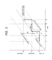
- FIG. 3 is a locus of focal length of a lens to which the first and second embodiments are applied.
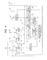
- FIG. 4 is a diagram of a second embodiment.
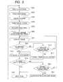
- FIG. 5 is a flowchart of the second embodiment.
- FIG. 6 is a diagram of a third embodiment.
- FIG. 7 is a flowchart of the third embodiment.
- FIG. 8 is a locus of focal length of a lens to which the third embodiment is applied.
- FIG. 9 is a locus of focal length of a conventional lens.
- FIG. 1 illustrates the configuration of a zoom lens apparatus 100 that is a first embodiment of an automatic focusing apparatus according to the present invention.
- the zoom lens apparatus 100 includes a focus lens 101 which moves in an optical axis direction so as to change the position of an imaging plane of the zoom lens apparatus 100.
- a focus motor 102 is connected to the focus lens 101.
- the focus motor 102 is driven by a focus driver 103 and moves the focus lens 101 in the optical axis direction.
- the position of the focus lens 101 is detected by a focus position detection unit 104.
- the zoom lens 105 moves in the optical axis direction and changes focal length of the zoom lens apparatus 100.
- a zoom motor 106 is connected to the zoom lens 105.
- the zoom motor 106 is driven by the zoom driver 107 and moves the zoom lens 105 in the optical axis direction.
- the position of the zoom lens 105 is detected by a zoom position detection unit 108.
- An iris motor 110 is connected to a movable stop 109.
- the iris motor 110 is driven by an iris driver 111 and drives the movable stop 109.
- the position of the movable stop 109 is detected by an iris position detection unit 112.
- a spectral prism 113 divides light that has passed through the focus lens 101 and the zoom lens 105 into two light beams.
- One light beam which is transmitted through the spectral prism 113 passes through a relay lens 123 and is made incident on an image pickup element 124.
- the other light beam which is reflected by the spectral prism 113 is made incident on a focus detection unit 114.
- the focus detection unit 114 includes a phase difference detection lens and a phase difference detection sensor.
- the focus detection unit 114 photoelectrically converts a pair of images (two images), which is formed by the two light beams divided by the phase difference detection lens, with a phase difference sensor.
- a zoom lens controller 115 includes a lens control unit 116 that drives the focus lens 101 on the basis of a result of a focus detection computing unit 118 and controls the zoom lens 105 and the movable stop 109.
- a field depth computing unit 117 calculates depth of field in the present focus position based on the position information received from the focus position detection unit 104, the zoom position detection unit 108, and the iris position detection unit 112 (or may read out the depth of field from a table).
- the focus detection computing unit 118 (a defocus computing unit) calculates a phase difference of a pair of image signals that is a part of a photographing light beam photoelectrically converted by the focus detection unit 114 and calculates a defocus amount.
- a focus detection time measuring unit 119 measures charge accumulating time of the phase difference sensor of the focus detection unit 114.
- An object speed calculation unit 120 calculates moving speed in the optical axis direction of an object on the basis of information received from the focus detection computing unit 118 and the focus detection time measuring unit 119.
- a maximum accumulating time period calculation unit 121 calculates a maximum charge accumulating time period (i.e., a maximum focus detection time period) of a sensor, in which the focus can be controlled within the depth of field, based on the depth of field information received from the field depth computing unit 117 and the object speed received from the object speed calculation unit 120 (or may read out the maximum accumulating time period from a table).
- a focus detection control unit 122 switches the control of the phase difference sensor according to the maximum charge accumulating time period calculated by the maximum accumulating time period calculation unit 121.
- phase difference sensor A method of controlling the phase difference sensor is described in detail below with reference to a flowchart of FIG. 2 and a locus of focal length of a lens illustrated in FIG. 3 in the configuration described above.
- step S201 in FIG. 2 the zoom lens controller 115 reads focus position detected by the focus position detection unit 104.
- step S202 the zoom lens controller 115 reads zoom position detected by the zoom position detection unit 108.
- step S203 the zoom lens controller 115 reads iris position detected by the iris position detection unit 112.
- the depth of field is described as being calculated by the above expression. However, the present invention is not limited to this. The depth of field may be read out from a table or the like.
- Fig. 3 shows a change in distance between a photographing lens and an object moving toward the photographing lens (moving upwardly in Fig. 3 ) as the time changes t1 to t5 and a change in distance in focus of the photographing lens (distance between the photographing lens and an object in focus) with respect to the time t1 to t5.
- step S205 the zoom lens controller 115 calculates object speed ⁇ defined by the following expression on the basis of processing time period T (time period between t1 and t3 in FIG. 3 ), which is a total of charge accumulating time period of the sensor and time period necessary for calculation of a defocus amount, and an amount of change (P2-P1 in FIG. 3 ) in the focal length of the focus lens (or may be read out from a table):
- step S206 the zoom lens controller 115 calculates a maximum accumulating time period (a maximum focus detection time period) MaxT (time period between t3 and t4 in FIG. 3 ) according to the following expression from the depth of field calculated in step S204 and the object speed ⁇ calculated in step S205.
- the zoom lens apparatus 100 shits to step S207.
- MaxT the maximum accumulating time period
- MaxT d ⁇ 1 - ⁇ ⁇ 1 / tan ⁇ - defocus amount calculation time period
- MaxT the maximum accumulating time period
- MaxT d ⁇ 2 - ⁇ ⁇ 2 / tan ⁇ - defocus amount calculation time period
- d1 represents rear depth of field
- d2 represents front depth of field.
- ⁇ 1 and ⁇ 2 are constants for maintaining a focus state within the depth of field.
- step S207 the zoom lens controller 115 activates the phase difference sensor, starts charge accumulation, and shifts to step S208.
- step S208 whether the charge accumulation of the sensor is completed is determined. When the charge accumulation is not completed (a charge accumulation amount in the sensor has not reached the threshold value), proceeding to step S210. When the charge accumulation is completed (at a point when the charge accumulation amount in the sensor reaches the threshold value), proceeding to step S209.
- step S210 whether charge accumulating time period of the sensor has exceeded the maximum accumulating time period MaxT is determined. When the charge accumulating time period has not exceeded the maximum accumulating time period MaxT, the process returns to step S208 and monitors a charge accumulation state again.
- step S211 since the charge accumulating time period of the sensor has exceeded the maximum accumulating time period, it is understood that the contrast of the object is low. Therefore, the zoom lens controller 115 increases a gain of the sensor and increases detection sensitivity in order to reduce the charge accumulating time and shifts to step S212. In step S212, the charge accumulation of the sensor is forcibly terminated and the process proceeds to step S213.
- step S209 since the charge accumulation is completed (the charge accumulation amount has reached the threshold value) before the charge accumulating time period reaches the maximum accumulating time period, the zoom lens controller 115 reduces the gain of the sensor and reduces the detection sensitivity in order to improve detection accuracy of the sensor and proceeds to step S213.
- the zoom lens apparatus 100 calculates a defocus amount from a sensor output, calculates a focus drive amount, and shifts to step S214.
- the zoom lens controller 115 compares waveforms of the pair of image signals photoelectrically converted by the phase difference sensor and used for the calculation of the phase difference.
- step S213 When it is determined that the waveforms are effective waveforms according to a predetermined determination method, the focus drive amount calculated in step S213 is determined effective and the process proceeds to step S215. When it is determined in step S214 that the waveforms of the pair of image signals are not effective waveforms, the focus drive amount calculated in step S213 is determined ineffective, and the process returns to step S207 to activate the phase difference sensor again and start charge accumulation.
- step S215 after driving the focus lens according to the focus drive amount calculated in step S214, the process returns to step S201 and repeats the series of operation.
- FIG. 4 is a diagram of a second embodiment of the present invention. Description of components same as those in the first embodiment illustrated in FIG. 1 is omitted. Differences from the first embodiment are described below.
- a focus drive amount calculation unit 401 calculates an extrapolated drive amount of a focus lens based on a maximum accumulating time period that is an output of the maximum accumulating time period calculation unit 121 and object speed that is an output of the object speed calculation unit 120.
- steps S201 to S207 are the same as those in the flowchart of FIG. 2 , description of the steps is omitted.
- step S208 whether the charge accumulation of the sensor is completed is determined. When the charge accumulation is not completed (the charge accumulation amount has not reached the threshold value), the process proceeds to step S210. When the charge accumulation is completed (the charge accumulation amount has reached the threshold value), the process proceeds to step S213. In step S210, whether charge accumulating time period has exceeded the maximum accumulating time period MaxT is determined. When the charge accumulating time period has not exceeded the maximum accumulating time period MaxT, the process returns to step S208 and monitors a charge accumulation state again. When the charge accumulating time period has exceeded the maximum accumulating time period MaxT (the charge accumulation amount in the sensor does not reach the threshold value within the maximum accumulating time period), the process proceeds to step S212. In step S212, the charge accumulation of the sensor is forcibly terminated and the process proceeds to step S213. In step S213, a defocus amount is calculated based on a sensor output to calculate a focus drive amount, and the process proceeds to step S214.
- step S214 as in the case of the first embodiment, on the basis of waveforms of the pair of image signals photoelectrically converted by the phase difference sensor and used for the calculation of the phase difference, whether the focus drive amount calculated in step S213 is effective is determined.
- the process proceeds to step S215.
- the focus drive amount is ineffective, the process proceeds to step S501.
- step S501 whether charge accumulating time period has exceeded the maximum accumulating time period MaxT is determined.
- the process returns to step S207 to activate the phase difference sensor again and resume the charge accumulation.
- the process proceeds to step S502.
- the zoom lens controller 115 calculates, in the focus drive amount calculation unit 401 (an extrapolated drive computing unit), an extrapolated drive amount according to the following expression on the basis of the object speed ⁇ calculated by the object speed calculation unit 120 illustrated in FIG.
- the extrapolated drive amount of the focus lens is a drive amount obtained by extrapolating a drive amount of the focus lens between time t3 and time t5 necessary for obtaining a focus state at time t5 from drive amounts of the focus lens at time t1 and time t3.
- Processing time T maximum accumulating time period MaxT + defocus amount calculation time period
- Extrapolated drive amount tan ⁇ ⁇ processing time period T
- step S215 when it is determined in step S214 that the focus drive amount is effective, the focus lens is driven according to the focus drive amount calculated in step S213.
- step S214 when it is determined in step S214 that the focus drive amount is ineffective, the focus lens is driven according to the extrapolated drive amount calculated in step S502.
- step S215 After driving the focus lens in step S215, the process returns to step S201 and repeats the series of operation.
- the maximum accumulating time period of the sensor is calculated from the moving speed of the object and the depth of field.
- the focus lens is driven on the basis of the sensor output.
- the accumulating time period has exceeded the maximum accumulating time period, the focus lens is driven by using the extrapolated drive amount calculated from the object speed. Consequently, even when a focus of the object cannot be temporarily detected, it is possible to maintain the in-focus state.
- the above description is made on the premise that the object speed ⁇ , the maximum accumulating time period MaxT, and the extrapolated drive amount of the focus lens are calculated.
- the present invention is not limited to this.
- the object speed ⁇ , the maximum accumulating time period MaxT, and the extrapolated drive amount of the focus lens may be read out from a table or the like and set.
- FIG. 6 is a diagram of a third embodiment of the present invention.
- the configuration of the third embodiment illustrated in FIG. 6 includes a focus drive speed calculation unit 402 in addition to the configuration of the second embodiment illustrated in FIG. 4 .
- the other components are the same as those in the second embodiment. Therefore, description of the same components as that in the second embodiment is omitted to avoid redundancy.
- FIG. 7 shows a change in distance between a photographing lens and an object moving toward the photographing lens (moving upwardly in Fig. 8 ) as the time changes t1 to t5 and a change in distance in focus of the photographing lens (distance between the photographing lens and an object in focus) with respect to the time t1 to t5.
- step S214 Processing in step S214 is the same as that in the second embodiment. However, when it is determined in step S214 that the focus drive amount is ineffective, the process returns to step S207 to activate the phase difference sensor again and star charge accumulation. When it is determined that the focus drive amount is effective in step S214, the process proceeds to step S601.
- step S601 when it is determined in the accumulation completion determination in step S208 that the charge accumulation is completed, the charge accumulating time period of the sensor is selected and, when it is determined that the charge accumulation is not completed, the maximum accumulating time period is selected.
- the focus drive speed calculation unit 402 sets drive speed of the focus lens (hereinafter referred to as focus drive speed) based on the defocus amount calculated in step S213 and the object speed calculated in step S205. As indicated by the locus of focal length of the lens illustrated in FIG. 8 , the focus drive speed is set such that the focus lens moves by a focus drive amount corresponding to a defocus amount (P2-P1 illustrated in Fig. 8 ) by the next focus control period (t5 in Fig. 8 ).
- the focus drive speed calculation unit 402 may set focus drive speed such that a drive amount corresponding to the defocus amount calculated in step S213 is obtained after a lapse of time of one of the charge accumulating time period and the maximum accumulating time period selected in step S601 after the focus lens starts to be driven.
- the focus drive speed may be set such that a drive amount corresponding to the defocus amount is obtained after a lapse of time equivalent to a sum of one of the charge accumulating time period and the maximum accumulating time period selected in step S601 and defocus amount calculation time period ( FIG. 8 ).
- step S215 the focus lens is driven according to the focus drive speed calculated in step S601. After starting the drive of the focus lens in step S215, the process returns to step S201 and repeats the series of operation.
- the focus lens can be driven according to the moving speed of the object. Therefore, it is possible to perform smooth focus adjustment.
- An automatic focusing apparatus includes: a focus detector photoelectrically converting at least a part of a photographing beam; a defocus computer calculating a defocus amount based on an output of the focus detector; a driver driving a focus lens based on the defocus amount; and a unit setting a maximum time period for charge accumulation in the focus detector.
- the defocus computer calculates a defocus amount using an output of the focus detector and outputs the defocus amount to the driver. If the accumulated charge in the focus detector does not reach the threshold within the period, when the period lapses, the defocus computer calculates a defocus amount using an output of the focus detector and outputs the defocus amount to the driver.
Landscapes
- Physics & Mathematics (AREA)
- General Physics & Mathematics (AREA)
- Optics & Photonics (AREA)
- Engineering & Computer Science (AREA)
- Multimedia (AREA)
- Signal Processing (AREA)
- Focusing (AREA)
- Automatic Focus Adjustment (AREA)
- Studio Devices (AREA)
Applications Claiming Priority (1)
| Application Number | Priority Date | Filing Date | Title |
|---|---|---|---|
| JP2009110868A JP5411568B2 (ja) | 2009-04-30 | 2009-04-30 | 自動焦点調整装置 |
Publications (3)
| Publication Number | Publication Date |
|---|---|
| EP2246721A2 true EP2246721A2 (de) | 2010-11-03 |
| EP2246721A3 EP2246721A3 (de) | 2012-12-26 |
| EP2246721B1 EP2246721B1 (de) | 2018-02-21 |
Family
ID=42358167
Family Applications (1)
| Application Number | Title | Priority Date | Filing Date |
|---|---|---|---|
| EP10157718.7A Active EP2246721B1 (de) | 2009-04-30 | 2010-03-25 | Automatisches Fokussierungsgerät |
Country Status (3)
| Country | Link |
|---|---|
| US (1) | US8000591B2 (de) |
| EP (1) | EP2246721B1 (de) |
| JP (1) | JP5411568B2 (de) |
Cited By (2)
| Publication number | Priority date | Publication date | Assignee | Title |
|---|---|---|---|---|
| EP2667232A1 (de) * | 2012-05-21 | 2013-11-27 | Canon Kabushiki Kaisha | Autofokusvorrichtung |
| EP2667231A4 (de) * | 2011-01-18 | 2015-04-01 | Fujifilm Corp | Autofokussystem |
Families Citing this family (7)
| Publication number | Priority date | Publication date | Assignee | Title |
|---|---|---|---|---|
| JP5419532B2 (ja) * | 2009-04-30 | 2014-02-19 | キヤノン株式会社 | 自動焦点調整装置 |
| JP5409201B2 (ja) * | 2009-08-28 | 2014-02-05 | キヤノン株式会社 | 焦点検出装置及び焦点検出方法 |
| US8760563B2 (en) | 2010-10-19 | 2014-06-24 | Hand Held Products, Inc. | Autofocusing optical imaging device |
| US8692927B2 (en) | 2011-01-19 | 2014-04-08 | Hand Held Products, Inc. | Imaging terminal having focus control |
| CN103033946B (zh) * | 2011-12-19 | 2015-07-22 | 中国航空工业集团公司洛阳电光设备研究所 | 一种双视场轴向变倍光学系统装调方法 |
| JP7766406B2 (ja) * | 2021-03-12 | 2025-11-10 | キヤノン株式会社 | 画像処理装置および画像処理方法 |
| JP2023101895A (ja) * | 2022-01-11 | 2023-07-24 | キヤノン株式会社 | 合焦情報取得装置、レンズ装置、撮像装置、合焦情報取得方法およびプログラム |
Citations (2)
| Publication number | Priority date | Publication date | Assignee | Title |
|---|---|---|---|---|
| JPH04217237A (ja) | 1990-12-19 | 1992-08-07 | Nikon Corp | カメラのオートフォーカス装置 |
| JPH08101337A (ja) | 1994-09-30 | 1996-04-16 | Nikon Corp | 自動焦点調節装置および焦点調節方法 |
Family Cites Families (19)
| Publication number | Priority date | Publication date | Assignee | Title |
|---|---|---|---|---|
| JPS632010A (ja) * | 1986-06-21 | 1988-01-07 | Minolta Camera Co Ltd | 自動焦点調節装置 |
| JP2605282B2 (ja) | 1987-05-21 | 1997-04-30 | ミノルタ株式会社 | 自動焦点調節装置 |
| US5008698A (en) * | 1987-09-28 | 1991-04-16 | Kyocera Corporation | Control apparatus for image sensor |
| JPH0617935B2 (ja) * | 1987-12-24 | 1994-03-09 | キヤノン株式会社 | 自動焦点調節装置 |
| GB2223139B (en) | 1988-08-31 | 1993-03-03 | Canon Kk | Automatic focusing apparatus |
| EP0427292B1 (de) | 1989-11-10 | 1996-02-07 | Canon Kabushiki Kaisha | Vorrichtung zum Bestimmen des Fokussierungszustandes und Kamera versehen mit einer solchen Vorrichtung |
| JP2911521B2 (ja) * | 1990-02-15 | 1999-06-23 | キヤノン株式会社 | センサ装置 |
| JP2757930B2 (ja) * | 1992-06-26 | 1998-05-25 | 株式会社ニコン | カメラの焦点検出装置 |
| JP3574157B2 (ja) * | 1993-03-12 | 2004-10-06 | 株式会社ニコン | 自動焦点調節カメラ |
| JP3561965B2 (ja) | 1994-09-07 | 2004-09-08 | 株式会社ニコン | 自動焦点調節装置 |
| JP3569973B2 (ja) * | 1994-09-07 | 2004-09-29 | 株式会社ニコン | 焦点調節装置 |
| JPH0968644A (ja) * | 1995-08-31 | 1997-03-11 | Nikon Corp | 自動焦点調節装置 |
| JP4289712B2 (ja) | 1999-03-10 | 2009-07-01 | キヤノン株式会社 | 焦点検出装置及び測距装置 |
| JP4882184B2 (ja) * | 2001-08-21 | 2012-02-22 | 株式会社ニコン | 焦点検出装置 |
| JP4208510B2 (ja) * | 2002-07-18 | 2009-01-14 | キヤノン株式会社 | ピント合わせ装置 |
| JP2004264827A (ja) | 2003-02-10 | 2004-09-24 | Chinon Ind Inc | 焦点距離検出方法及び合焦装置 |
| JP2005241774A (ja) * | 2004-02-25 | 2005-09-08 | Canon Inc | 自動焦点検出装置 |
| JP4874538B2 (ja) * | 2004-11-18 | 2012-02-15 | Hoya株式会社 | 焦点検出装置 |
| US7493030B2 (en) * | 2005-06-24 | 2009-02-17 | Nokia Corporation | Adaptive optical plane formation with rolling shutter |
-
2009
- 2009-04-30 JP JP2009110868A patent/JP5411568B2/ja not_active Expired - Fee Related
-
2010
- 2010-03-25 EP EP10157718.7A patent/EP2246721B1/de active Active
- 2010-04-28 US US12/769,191 patent/US8000591B2/en not_active Expired - Fee Related
Patent Citations (2)
| Publication number | Priority date | Publication date | Assignee | Title |
|---|---|---|---|---|
| JPH04217237A (ja) | 1990-12-19 | 1992-08-07 | Nikon Corp | カメラのオートフォーカス装置 |
| JPH08101337A (ja) | 1994-09-30 | 1996-04-16 | Nikon Corp | 自動焦点調節装置および焦点調節方法 |
Cited By (4)
| Publication number | Priority date | Publication date | Assignee | Title |
|---|---|---|---|---|
| EP2667231A4 (de) * | 2011-01-18 | 2015-04-01 | Fujifilm Corp | Autofokussystem |
| US9402019B2 (en) | 2011-01-18 | 2016-07-26 | Fujifilm Corporation | Autofocus system |
| EP2667232A1 (de) * | 2012-05-21 | 2013-11-27 | Canon Kabushiki Kaisha | Autofokusvorrichtung |
| US9288378B2 (en) | 2012-05-21 | 2016-03-15 | Canon Kabushiki Kaisha | Autofocus apparatus |
Also Published As
| Publication number | Publication date |
|---|---|
| US8000591B2 (en) | 2011-08-16 |
| US20100278520A1 (en) | 2010-11-04 |
| EP2246721A3 (de) | 2012-12-26 |
| JP5411568B2 (ja) | 2014-02-12 |
| JP2010262032A (ja) | 2010-11-18 |
| EP2246721B1 (de) | 2018-02-21 |
Similar Documents
| Publication | Publication Date | Title |
|---|---|---|
| EP2383597B1 (de) | Linsenvorrichtung | |
| EP2246721A2 (de) | Automatisches Fokussierungsgerät | |
| JP5247044B2 (ja) | 撮像装置 | |
| US7469098B2 (en) | Optical apparatus | |
| US9288378B2 (en) | Autofocus apparatus | |
| EP2141537A1 (de) | Bildaufnahmevorrichtung, Steuerungsverfahren dafür, Computerprogrammcode und Speichermedium | |
| EP1885119B1 (de) | Bildaufnahmevorrichtung und Fokussteuerungsverfahren | |
| JP6995561B2 (ja) | 像ブレ補正装置およびその制御方法、撮像装置 | |
| EP2557771B1 (de) | Fokusdetektor und Linsenvorrichtung und Bildaufnahmevorrichtung damit | |
| US9444993B2 (en) | Focus detecting apparatus, lens apparatus including the same, image pickup apparatus, and method of detecting defocus amount | |
| US8988541B2 (en) | Image pickup apparatus | |
| US8208058B2 (en) | Automatic focusing apparatus | |
| JP2007328360A (ja) | 自動焦点カメラ及び撮影方法 | |
| JP5420034B2 (ja) | 撮像装置、その制御方法、プログラム及び記憶媒体 | |
| JP5930979B2 (ja) | 撮像装置 | |
| US8027098B2 (en) | Focus lens apparatus |
Legal Events
| Date | Code | Title | Description |
|---|---|---|---|
| PUAI | Public reference made under article 153(3) epc to a published international application that has entered the european phase |
Free format text: ORIGINAL CODE: 0009012 |
|
| AK | Designated contracting states |
Kind code of ref document: A2 Designated state(s): AT BE BG CH CY CZ DE DK EE ES FI FR GB GR HR HU IE IS IT LI LT LU LV MC MK MT NL NO PL PT RO SE SI SK SM TR |
|
| PUAL | Search report despatched |
Free format text: ORIGINAL CODE: 0009013 |
|
| AK | Designated contracting states |
Kind code of ref document: A3 Designated state(s): AT BE BG CH CY CZ DE DK EE ES FI FR GB GR HR HU IE IS IT LI LT LU LV MC MK MT NL NO PL PT RO SE SI SK SM TR |
|
| RIC1 | Information provided on ipc code assigned before grant |
Ipc: G02B 7/38 20060101ALI20121120BHEP Ipc: H04N 5/232 20060101ALI20121120BHEP Ipc: G02B 7/28 20060101ALI20121120BHEP Ipc: G02B 7/34 20060101AFI20121120BHEP |
|
| 17P | Request for examination filed |
Effective date: 20130626 |
|
| RBV | Designated contracting states (corrected) |
Designated state(s): AT BE BG CH CY CZ DE DK EE ES FI FR GB GR HR HU IE IS IT LI LT LU LV MC MK MT NL NO PL PT RO SE SI SK SM TR |
|
| 17Q | First examination report despatched |
Effective date: 20130904 |
|
| GRAP | Despatch of communication of intention to grant a patent |
Free format text: ORIGINAL CODE: EPIDOSNIGR1 |
|
| INTG | Intention to grant announced |
Effective date: 20170907 |
|
| RAP1 | Party data changed (applicant data changed or rights of an application transferred) |
Owner name: CANON KABUSHIKI KAISHA |
|
| RIN1 | Information on inventor provided before grant (corrected) |
Inventor name: KARASAWA, KATSUMI |
|
| GRAS | Grant fee paid |
Free format text: ORIGINAL CODE: EPIDOSNIGR3 |
|
| GRAA | (expected) grant |
Free format text: ORIGINAL CODE: 0009210 |
|
| AK | Designated contracting states |
Kind code of ref document: B1 Designated state(s): AT BE BG CH CY CZ DE DK EE ES FI FR GB GR HR HU IE IS IT LI LT LU LV MC MK MT NL NO PL PT RO SE SI SK SM TR |
|
| REG | Reference to a national code |
Ref country code: GB Ref legal event code: FG4D |
|
| REG | Reference to a national code |
Ref country code: CH Ref legal event code: EP |
|
| REG | Reference to a national code |
Ref country code: AT Ref legal event code: REF Ref document number: 972359 Country of ref document: AT Kind code of ref document: T Effective date: 20180315 |
|
| REG | Reference to a national code |
Ref country code: IE Ref legal event code: FG4D |
|
| REG | Reference to a national code |
Ref country code: DE Ref legal event code: R096 Ref document number: 602010048567 Country of ref document: DE |
|
| REG | Reference to a national code |
Ref country code: FR Ref legal event code: PLFP Year of fee payment: 9 |
|
| REG | Reference to a national code |
Ref country code: NL Ref legal event code: MP Effective date: 20180221 |
|
| REG | Reference to a national code |
Ref country code: LT Ref legal event code: MG4D |
|
| REG | Reference to a national code |
Ref country code: AT Ref legal event code: MK05 Ref document number: 972359 Country of ref document: AT Kind code of ref document: T Effective date: 20180221 |
|
| PG25 | Lapsed in a contracting state [announced via postgrant information from national office to epo] |
Ref country code: FI Free format text: LAPSE BECAUSE OF FAILURE TO SUBMIT A TRANSLATION OF THE DESCRIPTION OR TO PAY THE FEE WITHIN THE PRESCRIBED TIME-LIMIT Effective date: 20180221 Ref country code: CY Free format text: LAPSE BECAUSE OF FAILURE TO SUBMIT A TRANSLATION OF THE DESCRIPTION OR TO PAY THE FEE WITHIN THE PRESCRIBED TIME-LIMIT Effective date: 20180221 Ref country code: NL Free format text: LAPSE BECAUSE OF FAILURE TO SUBMIT A TRANSLATION OF THE DESCRIPTION OR TO PAY THE FEE WITHIN THE PRESCRIBED TIME-LIMIT Effective date: 20180221 Ref country code: LT Free format text: LAPSE BECAUSE OF FAILURE TO SUBMIT A TRANSLATION OF THE DESCRIPTION OR TO PAY THE FEE WITHIN THE PRESCRIBED TIME-LIMIT Effective date: 20180221 Ref country code: ES Free format text: LAPSE BECAUSE OF FAILURE TO SUBMIT A TRANSLATION OF THE DESCRIPTION OR TO PAY THE FEE WITHIN THE PRESCRIBED TIME-LIMIT Effective date: 20180221 Ref country code: HR Free format text: LAPSE BECAUSE OF FAILURE TO SUBMIT A TRANSLATION OF THE DESCRIPTION OR TO PAY THE FEE WITHIN THE PRESCRIBED TIME-LIMIT Effective date: 20180221 Ref country code: NO Free format text: LAPSE BECAUSE OF FAILURE TO SUBMIT A TRANSLATION OF THE DESCRIPTION OR TO PAY THE FEE WITHIN THE PRESCRIBED TIME-LIMIT Effective date: 20180521 |
|
| PG25 | Lapsed in a contracting state [announced via postgrant information from national office to epo] |
Ref country code: BG Free format text: LAPSE BECAUSE OF FAILURE TO SUBMIT A TRANSLATION OF THE DESCRIPTION OR TO PAY THE FEE WITHIN THE PRESCRIBED TIME-LIMIT Effective date: 20180521 Ref country code: AT Free format text: LAPSE BECAUSE OF FAILURE TO SUBMIT A TRANSLATION OF THE DESCRIPTION OR TO PAY THE FEE WITHIN THE PRESCRIBED TIME-LIMIT Effective date: 20180221 Ref country code: GR Free format text: LAPSE BECAUSE OF FAILURE TO SUBMIT A TRANSLATION OF THE DESCRIPTION OR TO PAY THE FEE WITHIN THE PRESCRIBED TIME-LIMIT Effective date: 20180522 Ref country code: SE Free format text: LAPSE BECAUSE OF FAILURE TO SUBMIT A TRANSLATION OF THE DESCRIPTION OR TO PAY THE FEE WITHIN THE PRESCRIBED TIME-LIMIT Effective date: 20180221 Ref country code: LV Free format text: LAPSE BECAUSE OF FAILURE TO SUBMIT A TRANSLATION OF THE DESCRIPTION OR TO PAY THE FEE WITHIN THE PRESCRIBED TIME-LIMIT Effective date: 20180221 |
|
| PG25 | Lapsed in a contracting state [announced via postgrant information from national office to epo] |
Ref country code: IT Free format text: LAPSE BECAUSE OF FAILURE TO SUBMIT A TRANSLATION OF THE DESCRIPTION OR TO PAY THE FEE WITHIN THE PRESCRIBED TIME-LIMIT Effective date: 20180221 Ref country code: EE Free format text: LAPSE BECAUSE OF FAILURE TO SUBMIT A TRANSLATION OF THE DESCRIPTION OR TO PAY THE FEE WITHIN THE PRESCRIBED TIME-LIMIT Effective date: 20180221 Ref country code: PL Free format text: LAPSE BECAUSE OF FAILURE TO SUBMIT A TRANSLATION OF THE DESCRIPTION OR TO PAY THE FEE WITHIN THE PRESCRIBED TIME-LIMIT Effective date: 20180221 Ref country code: RO Free format text: LAPSE BECAUSE OF FAILURE TO SUBMIT A TRANSLATION OF THE DESCRIPTION OR TO PAY THE FEE WITHIN THE PRESCRIBED TIME-LIMIT Effective date: 20180221 |
|
| REG | Reference to a national code |
Ref country code: CH Ref legal event code: PL |
|
| REG | Reference to a national code |
Ref country code: DE Ref legal event code: R097 Ref document number: 602010048567 Country of ref document: DE |
|
| PG25 | Lapsed in a contracting state [announced via postgrant information from national office to epo] |
Ref country code: MC Free format text: LAPSE BECAUSE OF FAILURE TO SUBMIT A TRANSLATION OF THE DESCRIPTION OR TO PAY THE FEE WITHIN THE PRESCRIBED TIME-LIMIT Effective date: 20180221 Ref country code: DK Free format text: LAPSE BECAUSE OF FAILURE TO SUBMIT A TRANSLATION OF THE DESCRIPTION OR TO PAY THE FEE WITHIN THE PRESCRIBED TIME-LIMIT Effective date: 20180221 Ref country code: SM Free format text: LAPSE BECAUSE OF FAILURE TO SUBMIT A TRANSLATION OF THE DESCRIPTION OR TO PAY THE FEE WITHIN THE PRESCRIBED TIME-LIMIT Effective date: 20180221 Ref country code: SK Free format text: LAPSE BECAUSE OF FAILURE TO SUBMIT A TRANSLATION OF THE DESCRIPTION OR TO PAY THE FEE WITHIN THE PRESCRIBED TIME-LIMIT Effective date: 20180221 Ref country code: CZ Free format text: LAPSE BECAUSE OF FAILURE TO SUBMIT A TRANSLATION OF THE DESCRIPTION OR TO PAY THE FEE WITHIN THE PRESCRIBED TIME-LIMIT Effective date: 20180221 |
|
| REG | Reference to a national code |
Ref country code: BE Ref legal event code: MM Effective date: 20180331 |
|
| REG | Reference to a national code |
Ref country code: IE Ref legal event code: MM4A |
|
| PLBE | No opposition filed within time limit |
Free format text: ORIGINAL CODE: 0009261 |
|
| STAA | Information on the status of an ep patent application or granted ep patent |
Free format text: STATUS: NO OPPOSITION FILED WITHIN TIME LIMIT |
|
| PG25 | Lapsed in a contracting state [announced via postgrant information from national office to epo] |
Ref country code: LU Free format text: LAPSE BECAUSE OF NON-PAYMENT OF DUE FEES Effective date: 20180325 |
|
| 26N | No opposition filed |
Effective date: 20181122 |
|
| PG25 | Lapsed in a contracting state [announced via postgrant information from national office to epo] |
Ref country code: IE Free format text: LAPSE BECAUSE OF NON-PAYMENT OF DUE FEES Effective date: 20180325 |
|
| PG25 | Lapsed in a contracting state [announced via postgrant information from national office to epo] |
Ref country code: BE Free format text: LAPSE BECAUSE OF NON-PAYMENT OF DUE FEES Effective date: 20180331 Ref country code: CH Free format text: LAPSE BECAUSE OF NON-PAYMENT OF DUE FEES Effective date: 20180331 Ref country code: SI Free format text: LAPSE BECAUSE OF FAILURE TO SUBMIT A TRANSLATION OF THE DESCRIPTION OR TO PAY THE FEE WITHIN THE PRESCRIBED TIME-LIMIT Effective date: 20180221 Ref country code: LI Free format text: LAPSE BECAUSE OF NON-PAYMENT OF DUE FEES Effective date: 20180331 |
|
| PG25 | Lapsed in a contracting state [announced via postgrant information from national office to epo] |
Ref country code: MT Free format text: LAPSE BECAUSE OF NON-PAYMENT OF DUE FEES Effective date: 20180325 |
|
| PG25 | Lapsed in a contracting state [announced via postgrant information from national office to epo] |
Ref country code: TR Free format text: LAPSE BECAUSE OF FAILURE TO SUBMIT A TRANSLATION OF THE DESCRIPTION OR TO PAY THE FEE WITHIN THE PRESCRIBED TIME-LIMIT Effective date: 20180221 |
|
| PGFP | Annual fee paid to national office [announced via postgrant information from national office to epo] |
Ref country code: GB Payment date: 20200326 Year of fee payment: 11 |
|
| PG25 | Lapsed in a contracting state [announced via postgrant information from national office to epo] |
Ref country code: HU Free format text: LAPSE BECAUSE OF FAILURE TO SUBMIT A TRANSLATION OF THE DESCRIPTION OR TO PAY THE FEE WITHIN THE PRESCRIBED TIME-LIMIT; INVALID AB INITIO Effective date: 20100325 Ref country code: PT Free format text: LAPSE BECAUSE OF FAILURE TO SUBMIT A TRANSLATION OF THE DESCRIPTION OR TO PAY THE FEE WITHIN THE PRESCRIBED TIME-LIMIT Effective date: 20180221 |
|
| PG25 | Lapsed in a contracting state [announced via postgrant information from national office to epo] |
Ref country code: MK Free format text: LAPSE BECAUSE OF NON-PAYMENT OF DUE FEES Effective date: 20180221 |
|
| PGFP | Annual fee paid to national office [announced via postgrant information from national office to epo] |
Ref country code: FR Payment date: 20200326 Year of fee payment: 11 |
|
| PG25 | Lapsed in a contracting state [announced via postgrant information from national office to epo] |
Ref country code: IS Free format text: LAPSE BECAUSE OF FAILURE TO SUBMIT A TRANSLATION OF THE DESCRIPTION OR TO PAY THE FEE WITHIN THE PRESCRIBED TIME-LIMIT Effective date: 20180621 |
|
| GBPC | Gb: european patent ceased through non-payment of renewal fee |
Effective date: 20210325 |
|
| PG25 | Lapsed in a contracting state [announced via postgrant information from national office to epo] |
Ref country code: GB Free format text: LAPSE BECAUSE OF NON-PAYMENT OF DUE FEES Effective date: 20210325 Ref country code: FR Free format text: LAPSE BECAUSE OF NON-PAYMENT OF DUE FEES Effective date: 20210331 |
|
| PGFP | Annual fee paid to national office [announced via postgrant information from national office to epo] |
Ref country code: DE Payment date: 20250218 Year of fee payment: 16 |