EP2246725A2 - Microscope avec unité d'imagerie fixe et objectif - Google Patents
Microscope avec unité d'imagerie fixe et objectif Download PDFInfo
- Publication number
- EP2246725A2 EP2246725A2 EP10004532A EP10004532A EP2246725A2 EP 2246725 A2 EP2246725 A2 EP 2246725A2 EP 10004532 A EP10004532 A EP 10004532A EP 10004532 A EP10004532 A EP 10004532A EP 2246725 A2 EP2246725 A2 EP 2246725A2
- Authority
- EP
- European Patent Office
- Prior art keywords
- unit
- objective lens
- microscope
- observation
- optical axis
- Prior art date
- Legal status (The legal status is an assumption and is not a legal conclusion. Google has not performed a legal analysis and makes no representation as to the accuracy of the status listed.)
- Withdrawn
Links
- 238000003384 imaging method Methods 0.000 title claims abstract description 76
- 230000003287 optical effect Effects 0.000 claims abstract description 69
- 230000004907 flux Effects 0.000 claims abstract description 12
- 238000005286 illumination Methods 0.000 claims description 40
- 230000007246 mechanism Effects 0.000 description 40
- 230000008859 change Effects 0.000 description 3
- 238000010586 diagram Methods 0.000 description 2
- 230000000694 effects Effects 0.000 description 2
- 230000005484 gravity Effects 0.000 description 2
- 239000004973 liquid crystal related substance Substances 0.000 description 2
- 230000004048 modification Effects 0.000 description 2
- 238000012986 modification Methods 0.000 description 2
- 230000000007 visual effect Effects 0.000 description 2
- 239000012141 concentrate Substances 0.000 description 1
Images


Classifications
-
- G—PHYSICS
- G02—OPTICS
- G02B—OPTICAL ELEMENTS, SYSTEMS OR APPARATUS
- G02B21/00—Microscopes
- G02B21/24—Base structure
- G02B21/241—Devices for focusing
-
- G—PHYSICS
- G02—OPTICS
- G02B—OPTICAL ELEMENTS, SYSTEMS OR APPARATUS
- G02B21/00—Microscopes
- G02B21/36—Microscopes arranged for photographic purposes or projection purposes or digital imaging or video purposes including associated control and data processing arrangements
Definitions
- the present invention relates to a microscope that moves an objective lens along an observation optical axis with respect to a specimen.
- the microscope disclosed in Japanese Laid-open Patent Publication No. 2004-348089 and Japanese Laid-open Patent Publication No. 2006-337471 has a problem that when the objective lens and the camera are moved together as a unit, the weight balance becomes unstable, and as a result, it becomes difficult to focus on the specimen. This problem can be solved if the microscope is configured to be tolerant of a significant change in weight balance. However, it leads to a problem that the device configuration is complicated.
- FIG. 1 is a side view illustrating a configuration of a microscope 1 according to a first embodiment of the present invention.
- the microscope 1 has a base unit 20, a stage 30, a supporting unit 40, a rotary holding unit 50, a focusing unit 60, and an imaging unit 70.
- the base unit 20 is a mount part supporting the entire microscope 1.
- the stage 30 is supported by the base unit 20, and has a specimen table 30a on a top surface thereof.
- the specimen table 30a is a table on which a specimen S is put.
- the stage 30 is connected to a stage handle 30b by a moving mechanism (not shown), and makes a rotational movement in an X-Y direction shown the drawing and around an observation optical axis L by the turning operation of the stage handle 30b.
- the L-shaped supporting unit 42 is a member that a right prism is bent into an L shape, and has a body portion 42a joined to the strut unit 41 along the side surface of the strut unit 41 and an arm portion 42b extending from the upper part of the body portion 42a in a horizontal direction.
- the L-shaped supporting unit 42 is joined to the strut unit 41 so that the body portion 42a is along the side surface of the strut unit 41.
- the focusing-unit moving mechanism 43 has a focus handle 43a and a lift mechanism with a pinion and a rack (not shown) to which the focus handle 43a is connected.
- the focusing-unit moving mechanism 43 can move an enclosure 61 to be described below along the body portion 42a.
- the focusing-unit moving mechanism 43 can move the enclosure 61 in a direction parallel to the observation optical axis L.
- the focusing-unit moving mechanism 43 having the lift mechanism with the pinion and the rack is described as an example; however, the configuration of the focusing-unit moving mechanism 43 is not limited to this, and any other configuration can be employed as long as the focusing-unit moving mechanism 43 can move the enclosure 61 in the direction parallel to the observation optical axis L.
- the focusing-unit moving mechanism 43 can have a lift mechanism with a ball screw.
- the illumination light emitted from the light source 63a is concentrated into parallel light by the condenser lens 63c, and focused into a first light source image at the position of the aperture stop 63f by the condenser lens 63d. After that, the illumination light enters the condenser lens 63e via the field stop 63g, and is reflected to the side of the objective lens 62 by the optical-path splitting element 63b, and then falls on the objective lens 62 along the observation optical axis L.
- the illumination light is focused into a second light source image at the back focal position of the objective lens 62, and after the illumination light is concentrated into approximately-parallel light by passing through the objective lens 62, the specimen S is irradiated with the illumination light.
- the reflected light from the specimen S passes, as observation light, through the objective lens 62 and the optical-path splitting element 63b, and enters the imaging lens 70b via the zoom lenses 64a and 64b. Then, an observation image of the specimen S is focused on the imaging element 70c by the imaging lens 70b.
- FIG. 3 is a side view of a microscope 100 according to the first variation of the microscope 1 shown in FIG. 1 .
- a focusing mechanism 110 of the microscope 100 has a motor M for generating power for movement of the enclosure 61.
- the microscope 100 moves the enclosure 61 by driving the motor M.
- a rotation axis is connected to the rotation center of a pinion of the focusing mechanism 110, and the connected rotation axis is rotated by the motor M. Consequently, the operator does not have to perform the focus operation by rotating the focus handle 43a, and thus the burden on the operator can be reduced.
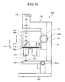
- FIG. 5 is a side view of a microscope 300 according to the third variation of the microscope 1 shown in FIG. 1 .
- a focusing unit 310 of the microscope 300 has a revolving nosepiece 311.
- the revolving nosepiece 311 holds a plurality of objective lenses 62, and sets desired one of the plurality of objective lenses 62 on the observation optical axis L.
- the revolving nosepiece 311 can be added to the focusing unit 310 because the weight balance at the time of movement of the objective lens 62 is stabilized as the objective lens 62 can be moved for focusing with the imaging unit 70 fixed. This makes it possible to easily switch among the objective lenses 62 of different magnifications from one another and set one of them on the observation optical axis L.
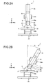
- the microscope 540 Since configurations of main parts of the microscope 540 are identical to those of the microscope 501 according to the second embodiment, the microscope 540 produces the same effect as the microscope 501 according to the second embodiment. Furthermore, as the microscope 540 includes the revolving nosepiece 542, an operator can switch to an objective lens to be used without removing a previously- used objective lens to replacing it to the objective lens to be used, so the work burden can be reduced. Other publicly-known means with a bearing can be used as the rotation mechanism of the revolving nosepiece.
Landscapes
- Physics & Mathematics (AREA)
- Chemical & Material Sciences (AREA)
- Analytical Chemistry (AREA)
- General Physics & Mathematics (AREA)
- Optics & Photonics (AREA)
- Engineering & Computer Science (AREA)
- Multimedia (AREA)
- Microscoopes, Condenser (AREA)
Applications Claiming Priority (2)
| Application Number | Priority Date | Filing Date | Title |
|---|---|---|---|
| JP2009111399A JP2010262071A (ja) | 2009-04-30 | 2009-04-30 | 顕微鏡 |
| JP2009151475A JP2011008032A (ja) | 2009-06-25 | 2009-06-25 | 顕微鏡 |
Publications (2)
| Publication Number | Publication Date |
|---|---|
| EP2246725A2 true EP2246725A2 (fr) | 2010-11-03 |
| EP2246725A3 EP2246725A3 (fr) | 2011-01-26 |
Family
ID=42340836
Family Applications (1)
| Application Number | Title | Priority Date | Filing Date |
|---|---|---|---|
| EP10004532A Withdrawn EP2246725A3 (fr) | 2009-04-30 | 2010-04-29 | Microscope avec unité d'imagerie fixe et objectif |
Country Status (2)
| Country | Link |
|---|---|
| US (1) | US8289383B2 (fr) |
| EP (1) | EP2246725A3 (fr) |
Families Citing this family (5)
| Publication number | Priority date | Publication date | Assignee | Title |
|---|---|---|---|---|
| EP2587313B1 (fr) * | 2011-10-20 | 2016-05-11 | Samsung Electronics Co., Ltd | Système de mesure optique et procédé de mesure de dimension critique de nanostructure |
| JP5969808B2 (ja) * | 2012-04-27 | 2016-08-17 | オリンパス株式会社 | 顕微鏡装置 |
| WO2014071390A1 (fr) * | 2012-11-05 | 2014-05-08 | Inscopix, Inc. | Dispositifs, systèmes et procédés d'imagerie miniaturisés |
| DE102016111949B4 (de) * | 2016-06-30 | 2018-03-01 | Leica Microsystems Cms Gmbh | Laser-Mikroskopsystem |
| CN118591750A (zh) * | 2021-07-02 | 2024-09-03 | 富鲁达公司 | 用于微流体装置的成角度的照明系统 |
Citations (2)
| Publication number | Priority date | Publication date | Assignee | Title |
|---|---|---|---|---|
| JP2004348089A (ja) | 2003-05-26 | 2004-12-09 | Olympus Corp | 顕微鏡 |
| JP2006337471A (ja) | 2005-05-31 | 2006-12-14 | Keyence Corp | 支持装置およびそれを備えた顕微鏡 |
Family Cites Families (17)
| Publication number | Priority date | Publication date | Assignee | Title |
|---|---|---|---|---|
| US4210384A (en) * | 1976-09-11 | 1980-07-01 | Carl Zeiss-Stiftung | Inverted-design optical microscope |
| US4855823A (en) * | 1988-05-05 | 1989-08-08 | Applied Engineering Products Co. | Imaging assembly and mounting for surveillance viewing under remote control |
| US4901146A (en) * | 1988-05-05 | 1990-02-13 | Applied Engineering Products Co. | Imaging assembly and mounting for surveillance viewing under remote control |
| US6099522A (en) * | 1989-02-06 | 2000-08-08 | Visx Inc. | Automated laser workstation for high precision surgical and industrial interventions |
| JP2925647B2 (ja) * | 1990-04-16 | 1999-07-28 | オリンパス光学工業株式会社 | 顕微鏡変倍装置 |
| US5434703A (en) * | 1991-10-09 | 1995-07-18 | Fuji Photo Optical Co., Ltd. | Binocular stereomicroscope |
| US5266791A (en) * | 1991-10-17 | 1993-11-30 | Fuji Photo Optical Co., Ltd. | Autofocus binocular stereomicroscope |
| US5689339A (en) * | 1991-10-23 | 1997-11-18 | Nikon Corporation | Alignment apparatus |
| US5668660A (en) * | 1994-11-29 | 1997-09-16 | Hunt; Gary D. | Microscope with plural zoom lens assemblies in series |
| JP4084061B2 (ja) * | 2002-03-18 | 2008-04-30 | 独立行政法人科学技術振興機構 | 高安定性光学顕微鏡 |
| US20050157299A1 (en) * | 2004-01-15 | 2005-07-21 | Heffelfinger David M. | Optical analysis systems |
| US6853454B1 (en) * | 2004-01-15 | 2005-02-08 | Alpha Innotech Corporation | Optical analysis systems |
| US6995901B2 (en) * | 2004-01-15 | 2006-02-07 | Alpha Innotech Corporation | Optical analysis systems |
| JP4558366B2 (ja) * | 2004-03-30 | 2010-10-06 | オリンパス株式会社 | システム顕微鏡 |
| CN101278190B (zh) * | 2005-09-29 | 2012-12-19 | 奥林巴斯株式会社 | 焦点位置决定方法、焦点位置决定装置、微弱光检测装置及微弱光检测方法 |
| JP5307539B2 (ja) * | 2006-05-31 | 2013-10-02 | オリンパス株式会社 | 生体試料撮像方法および生体試料撮像装置 |
| JP5047669B2 (ja) * | 2007-04-04 | 2012-10-10 | オリンパス株式会社 | 走査型共焦点顕微鏡装置 |
-
2010
- 2010-04-29 EP EP10004532A patent/EP2246725A3/fr not_active Withdrawn
- 2010-04-30 US US12/771,021 patent/US8289383B2/en not_active Expired - Fee Related
Patent Citations (2)
| Publication number | Priority date | Publication date | Assignee | Title |
|---|---|---|---|---|
| JP2004348089A (ja) | 2003-05-26 | 2004-12-09 | Olympus Corp | 顕微鏡 |
| JP2006337471A (ja) | 2005-05-31 | 2006-12-14 | Keyence Corp | 支持装置およびそれを備えた顕微鏡 |
Also Published As
| Publication number | Publication date |
|---|---|
| US20100277581A1 (en) | 2010-11-04 |
| EP2246725A3 (fr) | 2011-01-26 |
| US8289383B2 (en) | 2012-10-16 |
Similar Documents
| Publication | Publication Date | Title |
|---|---|---|
| US6226118B1 (en) | Optical microscope | |
| US5818637A (en) | Computerized video microscopy system | |
| US6400395B1 (en) | Computerized video microscopy system | |
| JP6634263B2 (ja) | 顕微鏡 | |
| EP2246725A2 (fr) | Microscope avec unité d'imagerie fixe et objectif | |
| JP2004086009A (ja) | 走査型レーザ顕微鏡システム | |
| JP2003185929A (ja) | 実体顕微鏡 | |
| JPH10339845A (ja) | モニタ観察型顕微鏡 | |
| US6396532B1 (en) | Computer controlled video microscopy system | |
| JP7025530B2 (ja) | 広領域の共焦点及び多光子顕微鏡で用いる動的フォーカス・ズームシステム | |
| JP2009282198A (ja) | 顕微鏡装置 | |
| JP6978592B2 (ja) | 広領域の共焦点及び多光子顕微鏡で用いる動的フォーカス・ズームシステム | |
| JP2011027906A (ja) | 顕微鏡 | |
| JP3877380B2 (ja) | 光学顕微鏡 | |
| JP4653292B2 (ja) | システム顕微鏡 | |
| EP1586930B1 (fr) | Microscope universel | |
| JP2010262071A (ja) | 顕微鏡 | |
| JP2011008032A (ja) | 顕微鏡 | |
| JP2009116054A (ja) | 光学装置および顕微鏡 | |
| JPH11183805A (ja) | 手術用顕微鏡 | |
| JPH10282430A (ja) | 倒立型顕微鏡 | |
| JP2015127775A (ja) | 拡大観察装置 | |
| JP3868026B2 (ja) | 顕微鏡 | |
| WO2022208223A1 (fr) | Microscope optique | |
| JP2024154082A (ja) | レンズユニットおよび拡大観察装置 |
Legal Events
| Date | Code | Title | Description |
|---|---|---|---|
| PUAI | Public reference made under article 153(3) epc to a published international application that has entered the european phase |
Free format text: ORIGINAL CODE: 0009012 |
|
| AK | Designated contracting states |
Kind code of ref document: A2 Designated state(s): AT BE BG CH CY CZ DE DK EE ES FI FR GB GR HR HU IE IS IT LI LT LU LV MC MK MT NL NO PL PT RO SE SI SK SM TR |
|
| AX | Request for extension of the european patent |
Extension state: AL BA ME RS |
|
| PUAL | Search report despatched |
Free format text: ORIGINAL CODE: 0009013 |
|
| AK | Designated contracting states |
Kind code of ref document: A3 Designated state(s): AT BE BG CH CY CZ DE DK EE ES FI FR GB GR HR HU IE IS IT LI LT LU LV MC MK MT NL NO PL PT RO SE SI SK SM TR |
|
| AX | Request for extension of the european patent |
Extension state: AL BA ME RS |
|
| 17P | Request for examination filed |
Effective date: 20110427 |
|
| STAA | Information on the status of an ep patent application or granted ep patent |
Free format text: STATUS: THE APPLICATION HAS BEEN WITHDRAWN |
|
| 18W | Application withdrawn |
Effective date: 20130218 |