EP2246748A1 - Appareil de développement et appareil de formation d'image de photographie électronique - Google Patents
Appareil de développement et appareil de formation d'image de photographie électronique Download PDFInfo
- Publication number
- EP2246748A1 EP2246748A1 EP09709443A EP09709443A EP2246748A1 EP 2246748 A1 EP2246748 A1 EP 2246748A1 EP 09709443 A EP09709443 A EP 09709443A EP 09709443 A EP09709443 A EP 09709443A EP 2246748 A1 EP2246748 A1 EP 2246748A1
- Authority
- EP
- European Patent Office
- Prior art keywords
- developer
- bearing member
- particles
- developer bearing
- less
- Prior art date
- Legal status (The legal status is an assumption and is not a legal conclusion. Google has not performed a legal analysis and makes no representation as to the accuracy of the status listed.)
- Granted
Links
Images


Classifications
-
- G—PHYSICS
- G03—PHOTOGRAPHY; CINEMATOGRAPHY; ANALOGOUS TECHNIQUES USING WAVES OTHER THAN OPTICAL WAVES; ELECTROGRAPHY; HOLOGRAPHY
- G03G—ELECTROGRAPHY; ELECTROPHOTOGRAPHY; MAGNETOGRAPHY
- G03G9/00—Developers
- G03G9/08—Developers with toner particles
- G03G9/083—Magnetic toner particles
- G03G9/0831—Chemical composition of the magnetic components
- G03G9/0833—Oxides
-
- G—PHYSICS
- G03—PHOTOGRAPHY; CINEMATOGRAPHY; ANALOGOUS TECHNIQUES USING WAVES OTHER THAN OPTICAL WAVES; ELECTROGRAPHY; HOLOGRAPHY
- G03G—ELECTROGRAPHY; ELECTROPHOTOGRAPHY; MAGNETOGRAPHY
- G03G9/00—Developers
- G03G9/08—Developers with toner particles
- G03G9/083—Magnetic toner particles
- G03G9/0835—Magnetic parameters of the magnetic components
-
- G—PHYSICS
- G03—PHOTOGRAPHY; CINEMATOGRAPHY; ANALOGOUS TECHNIQUES USING WAVES OTHER THAN OPTICAL WAVES; ELECTROGRAPHY; HOLOGRAPHY
- G03G—ELECTROGRAPHY; ELECTROPHOTOGRAPHY; MAGNETOGRAPHY
- G03G2215/00—Apparatus for electrophotographic processes
- G03G2215/06—Developing structures, details
- G03G2215/0602—Developer
- G03G2215/0604—Developer solid type
- G03G2215/0607—Developer solid type two-component
- G03G2215/0609—Developer solid type two-component magnetic brush
Definitions
- the present invention relates to a developing apparatus to be used for developing an electrostatic latent image formed on an electrostatic latent image-bearing member such as a photosensitive member or an electrostatic recording derivative, and an electrophotographic image-forming apparatus including the developing apparatus.
- Electrophotography generally involves the utilization of a photoconductive substance, and includes: forming an electrostatic latent image on an electrostatic latent image-bearing member (photosensitive drum) by various means; applying a developing bias to a developing zone; developing the electrostatic latent image with a developer to form a toner image; transferring the toner image onto a transfer material such as paper as required; and fixing the toner image on the transfer material with heat or pressure to provide a copy.
- Developing methods in the electrophotography are mainly classified into a one-component developing method in which there is no need for a carrier and a two-component developing method involving the use of a carrier.
- a developing apparatus employing the one-component developing method is advantageous in that since no carrier is needed, the frequency at which toner must be exchanged owing to deterioration in the toner can be reduced; in addition, there is no need to provide the developing apparatus with, for example, a mechanism for adjusting the concentration of the toner or carrier, so the developing apparatus itself can be reduced in size and weight.
- Japanese Patent Application Laid-Open No. 2005-157318 discloses that the particle size of a developer (toner) is reduced and the saturation magnetization of the developer is reduced in order that the image quality of a copy may be higher.
- Japanese Patent Application Laid-Open No. 2003-323042 proposes a developer bearing member having a resin layer which is incorporated with graphitized particles having a degree of graphitization p(002) of 0.20 to 0.95 and an indentation hardness HUT[68] of 15 to 60 are incorporated.
- the charge-up of the developer is alleviated by the effect of the graphitized particles of enhancing the performance of rapidly and stably charging the developer.
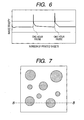
- predetermined printing mode refers to the following printing condition: after 1,000 or more sheets are continuously printed, a pause period of 30 minutes to 2 hours is set, and then 1,000 or more sheets are printed again.
- the inventors have found that, when electrophotographic images are formed according to the printing mode, an image density on the first sheet after the rest is extremely higher than an image density before the pause. In addition, the inventors have found that an image density gradually returns to the image density before the pause by continuously performing image formation after the pause.
- the present invention is aimed at providing a developing apparatus capable of suppressing such an irregular fluctuation in image density as described above, and an electrophotographic image-forming apparatus including the developing apparatus.
- the inventors of the present invention have made investigation into the above-mentioned increase of image density occurring after a pause. As a result, the inventors have found the correlation between the increase and the charge-up of a developer. That is, the inventors have considered as follows: mirror force affecting the developer which has undergone charge-up owing to extensive operation is weakened by setting a pause period, and an image can be easily developed with the developer at the time of printing after a pause, whereby an image density increases.
- the inventors of the present invention have conducted investigation on the basis of the above consideration. As a result, the inventors have found that a combination of a specific developer and a developer bearing member having a specific surface shape is effective in solving the above problems.
- a developing apparatus comprises at least: a photosensitive drum for forming an electrostatic latent image; a developer for developing the electrostatic latent image; a developer bearing member for bearing and conveying the developer; and a developer layer thickness-regulating unit placed close to the developer bearing member so as to regulate an amount of the developer bore and conveyed by the developer bearing member, wherein: the developer is a negatively chargeable, one-component, magnetic toner, and comprises magnetic toner particles each comprising at least a binder resin and magnetic iron oxide particle, the developer has a saturation magnetization of 20 Am 2 /kg or more and 40 Am 2 /kg or less in a magnetic field of 795.8 kA/m, and has a weight-average particle diameter (D 4 ) of 4.0 ⁇ m or more and 8.0 ⁇ m or less, wherein a ratio X of an amount of Fe(2+) to a total amount of Fe in the magnetic iron oxide particle is 34% or more and 50% or less, the total amount of Fe being an amount
- the electrophotographic image-forming apparatus is characterized by including the above developing apparatus.
- a fluctuation in image density can be suppressed even in a discontinuous printing mode provided with a pause period.
- the inventors of the present invention have conducted investigations into a discontinuous printing mode provided with a pause period. As a result, the inventors have found that, when a pause period of 30 minutes to 2 hours is provided after continuous printing of 1,000 or more sheets, a difference in image density is liable to occur between before and after the pause. As shown in FIG. 6 , the density difference in this case is such a phenomenon that image density at the time point when continuous printing is restarted after a pause is higher than image density before the pause, and image density returns to the image density before the pause by continuous printing of about 1,000 sheets.
- the present inventors have made an investigation into the electrical characteristics of a developer, and the component and surface shape of a developer bearing member with the view of suppressing the fluctuation of image density after a pause as compared with image density before the pause.
- the triboelectric charge quantity of a developer constant is effective in suppressing a fluctuation in image density.
- the following approaches are effective: the triboelectric charging of the developer is quickly performed, and excessive triboelectric charging is suppressed.
- the inventors of the present invention have conducted extensive investigations while paying attention to components for the magnetic iron oxide particles of a developer and a developer bearing member, and a relationship between the particle diameter of the developer and the surface shape of the developer bearing member. As a result, the inventors have found that a developing apparatus in which a specific developer and a specific developer bearing member are combined can suppress the above fluctuation in image density better.
- the present invention will be described in detail by way of a preferred embodiment.
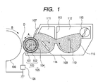
- the developing apparatus according to the present invention includes:
- the developing apparatus forms a toner image through the following procedure: while a developer layer is formed on the developer bearing member 105 by the magnetic blade 107, the developer on the developer bearing member 105 is conveyed to the developing zone D opposite to an electrostatic latent image-bearing member 106, and then an electrostatic latent image on the electrostatic latent image-bearing member 106 is developed with the conveyed developer.
- the developer is a negatively chargeable, one-component, magnetic toner having magnetic toner particles containing a binder resin and a magnetic iron oxide particle, and satisfying the following requirements (A1) to (A3):
- the negatively chargeable, one-component, magnetic toner according to the present invention has a weight-average particle diameter (D 4 ) of 4.0 ⁇ m or more and 8.0 ⁇ m or less.
- D 4 weight-average particle diameter
- the weight-average particle diameter (D 4 ) is less than 4.0 ⁇ m, the amount of a magnetic powder in one toner particle is relatively reduced, so the effect of using the magnetic iron oxide particles becomes less.
- the surface area of the toner particles increases, so the developer is apt to undergo charge-up at the time of continuous printing. Accordingly, the weight-average particle diameter (D 4 ) of less than 4.0 ⁇ m is disadvantageous to the suppression of the fluctuation of image density after a pause as compared with image density before the pause.
- the weight-average particle diameter (D 4 ) exceeds 8.0 ⁇ m, the surface area of the toner particles is reduced, so the charge quantity of the developer is apt to be insufficient. Accordingly, the weight-average particle diameter (D 4 ) in excess of 8.0 ⁇ m is disadvantageous to the suppression of a fluctuation or reduction in image density.
- the Fe element dissolution ratio is an indicator showing the extent to which the magnetic iron oxide particles are dissolved when the dissolution starts from their surfaces.
- a state in which the Fe element dissolution ratio is 0 mass% is a state in which none of the magnetic iron oxide particles is dissolved.
- a state in which the Fe element dissolution ratio is 10 mass% is a state in which the surfaces of the magnetic iron oxide particles are dissolved so that 90 mass% of Fe may remain with respect to the total amount of Fe of the magnetic iron oxide particles. Therefore, the phrase "total amount of Fe dissolved until the Fe element dissolution ratio reaches 10 mass%" refers to the total amount of Fe present in the dissolved regions of the magnetic iron oxide particles.
- the ratio X is a ratio of the amount of Fe(2+) to the total amount of Fe.
- a state in which the Fe element dissolution ratio is 100 mass% is a state in which the magnetic iron oxide particles are completely dissolved.
- the ratio X is less than 34%, the developer is apt to undergo charge-up at the time of continuous duration, so the fluctuation of image density after a pause as compared with image density before the pause is apt to occur.
- the ratio X exceeds 50%, the magnetic iron oxide particles are susceptible to oxidation, so a fluctuation in image density is apt to occur as in the case of the foregoing.
- a ratio (X/Y) of X to Y is preferably more than 1.00 and 1.30 or less:
- X represents a ratio of the amount of Fe(2+) to the total amount of Fe dissolved when the Fe element dissolution ratio is 10 mass% with respect to the total amount of Fe (hereinafter referred to also as “surface Fe(2+)”); and
- Y represents a ratio of the amount of Fe(2+) to the total amount of Fe in the remaining 90 mass% (hereinafter referred to also as "internal Fe(2+)”).
- a core particle is formed by incorporating a metal element into each magnetic iron oxide particle, and a coating layer containing various metal elements is formed on the surface of the core particle.
- a coating layer containing various metal elements is formed on the surface of the core particle.
- the amount of silicon in the core particles in terms of a silicon element is preferably 0.20 mass% or more and 1.50 mass% or less, or more preferably 0.25 mass% or more and 1.00 mass% or less, with respect to the entirety of the magnetic iron oxide particles.
- the amount of silicon in the coating layers in terms of an Si element is preferably 0.05 mass% or more and 0.50 mass% or less with respect to the entirety of the magnetic iron oxide particles.
- the amount of aluminum in the coating layers in terms of an aluminum element is preferably 0.05 mass% or more and 0.50 mass% or less, or more preferably 0.10 mass% or more and 0.25 mass% or less, with respect to the entirety of the magnetic iron oxide particles.
- the triboelectric chargeability of the developer with the developer bearing member used in the present invention is apt to be stabilized.
- the magnetic iron oxide particles used in the present invention have an average primary particle diameter of preferably 0.10 ⁇ m or more and 0.30 ⁇ m or less, or more preferably 0.10 ⁇ m or more and 0.20 ⁇ m or less.
- an average primary particle diameter of the magnetic iron oxide particles By setting the average primary particle diameter of the magnetic iron oxide particles to 0.20 ⁇ m or less, a magnetic powder can be dispersed uniformly in the magnetic toner particles, and the effect of suppressing the charge-up of the developer can be enhanced.
- the average primary particle diameter of the magnetic iron oxide particles to 0.10 ⁇ m or more, Fe(2+) is inhibited from being oxidized, and the amount of Fe(2+) can be stably controlled.
- the magnetic iron oxide particles have a magnetization of preferably 86.0 Am 2 /kg or more, or more preferably 87.0 Am 2 /kg or more, in an external magnetic field of 795.8 kA/m.
- magnetic ears are particularly favorably formed on a developing sleeve, and hence good developability can be obtained.
- the content of the magnetic iron oxide particles to be used is preferably 20 parts by mass or more and 150 parts by mass or less, or more preferably 50 parts by mass or more and 120 parts by mass or less, with respect to 100 parts by mass of the binder resin of the developer. By setting the content within the range, the saturation magnetization of the developer can be controlled to be desirable.
- a general method of producing magnetite particles can be employed as a method of producing the magnetic iron oxide particles used in the present invention.
- a particularly preferable production method will be specifically described below.
- the magnetic iron oxide particles used in the present invention can be produced by oxidizing ferrous hydroxide slurry obtained by mixing and neutralizing an aqueous solution of a ferrous salt with an alkaline solution.
- the ferrous salt to be utilized has only to be a water-soluble salt, and examples of the ferrous salt include ferrous sulfate and ferrous chloride.
- a water-soluble silicate (such as sodium silicate) is preferably added to and mixed in the ferrous salt so that the content of the water-soluble silicate in terms of a silicon element may be 0.20 mass% or more and 1.50 mass% or less with respect to the final total amount of the magnetic iron oxide particles.
- the resultant aqueous solution of the ferrous salt containing a silicon element is mixed and neutralized with the alkaline solution so that the ferrous hydroxide slurry can be produced.
- an aqueous solution of an alkali metal hydroxide such as an aqueous solution of sodium hydroxide or an aqueous solution of potassium hydroxide can be used as the alkaline solution.
- the amount of the alkaline solution at the time of producing the ferrous hydroxide slurry has only to be adjusted depending on a required shape of each magnetic iron oxide particle.
- spherical particles are obtained when the amount is adjusted so that the pH of the ferrous hydroxide slurry may be less than 8.0.
- hexahedral particles are obtained when the amount is adjusted so that the pH is 8.0 or more and 9.5 or less; octahedral particles are obtained when the amount is adjusted so that the pH exceed 9.5. In view of the foregoing, the amount is appropriately adjusted.
- an oxidation reaction is performed while an oxidizing gas, or preferably air, is blown into the slurry.
- an oxidizing gas or preferably air
- the temperature of the slurry is kept at preferably 60 to 100°C, or particularly preferably 80 to 95°C by heating.
- the oxidation reaction be controlled in order that the ratio X in the magnetic iron oxide particles may be controlled to fall within the range of the present invention.
- the amount of the oxidizing gas to be blown is gradually reduced with the progress of the oxidation of ferrous hydroxide so that the amount of the gas to be blown at the final stage is small.
- the amount of air to be blown is preferably controlled as described below for slurry containing 100 moles of an iron element. The amount of air to be blown is gradually reduced in the following ranges:
- an aqueous solution of sodium silicate and an aqueous solution of aluminum sulfate are simultaneously charged into the resultant slurry of the iron oxide particles, and the pH of the mixture is adjusted to 5 or more and 9 or less so that a coating layer containing silicon and aluminum may be formed on the surface of each particle.
- the resultant slurry of the magnetic iron oxide particles each having the coating layer is subjected to filtration, washing, drying, and pulverization treatment by ordinary methods so that magnetic iron oxide particles may be obtained.
- shear stress is preferably applied to the slurry at the time of the production of the magnetic iron oxide particles to loosen the magnetic iron oxide particles once with a view to improving the fine dispersibility of the magnetic iron oxide particles in the magnetic toner particles.
- the binder resin As the binder resin, the following compounds may be used: a styrene-type resin, a styrene-type copolymer resin, a polyester resin, a polyol resin, a polyvinyl chloride resin, a phenolic resin, a naturally-modified phenolic resin, a natural-resin-modified maleic resin, an acrylic resin, a methacrylic resin, polyvinyl acetate, a silicone resin, a polyurethane resin, a polyamide resin, a furan resin, an epoxy resin, a xylene resin, a polyvinyl butyral, a terpene resin, a coumarone-indene resin, and a petroleum-type resin.
- a styrene-type resin a styrene-type copolymer resin
- a polyester resin As the binder resin, the following compounds may be used: a styrene-type resin,
- examples of preferably used resins include the styrene-type copolymer resin, the polyester resin, a mixture of a polyester resin and a styrene-type copolymer resin, or a hybrid resin obtained by partial reaction of a polyester resin and a styrene-type copolymer resin.
- Examples of monomers constituting a polyester-type unit in the polyester resin or the hybrid resin include the following compounds.
- an alcohol component examples include the following: ethylene glycol; propylene glycol; 1,3-butanediol; 1,4-butanediol; 2,3-butanediol; diethylene glycol; triethylene glycol; 1,5-pentanediol; 1,6-hexanediol; neopentyl glycol; 2-ethyl-1,3-hexanediol; hydrogenated bisphenol A; and a bisphenol derivative represented by the following structural formula (1); and diols represented by the following structural formula (2).
- R represents an ethylene or propylene group, x and y each independently represent an integer of 1 or more, and the average of x+y is 2 to 10.
- R' represents -CH 2 CH 2 -, CH 2 CH(CH 3 ), or CH 2 -C(CH 3 ) 2 .
- acid components include the following: benzene dicarboxylic acids, or anhydrides thereof such as phthalic acid, terephthalic acid, isophthalic acid, and phthalic anhydride; alkyldicarboxylic acids, or anhydrides thereof such as succinic acid, adipic acid, sebacic acid, and azelaic acid; succinic acids each substituted with an alkl group or an alkenyl group having 6 or more and less than 18 carbon atoms or anhydrides thereof; and unsaturated dicarboxylic acids such as fumaric acid, maleic acid, citraconic acid, and itaconic acid, or their anhydrides.
- benzene dicarboxylic acids or anhydrides thereof such as phthalic acid, terephthalic acid, isophthalic acid, and phthalic anhydride
- alkyldicarboxylic acids, or anhydrides thereof such as succinic acid, adipic acid, sebacic acid, and azelaic acid
- the polyester resin or the polyester-type unit preferably includes a crosslinking structure formed of a polyvalent carboxylic acid having 3 or more valencies or anhydrides thereof and/or a polyhydric alcohol having 3 or more valencies.
- the polyvalent carboxylic acid having 3 or more valencies or anhydrides thereof include 1,2,4-benzenetricarboxylic acid, 1,2,4-cyclohexanetricarboxylic acid, 1,2,4-naphthalenetricarboxylic acid, pyromellitic acid, and acid anhydrides thereof or lower alkyl esters thereof.
- the polyhydric alcohol having 3 or more valencies include 1,2,3-propanetriol, trimethylolpropane, hexanetriol, and pentaerythritol.
- Styrenes such as o-methylstyrene, m-methylstyrene, p-methylstyrene, p-methoxystyrene, p-phenylstyrene, p-chlorstyrene, 3,4-dichlorstyrene, p-ethylstyrene, 2,4-dimethylstyrene, p-n-butylstyrene, p-tert-butylstyrene, p-n-hexylstyrene, p-n-octylstyrene, p-n-nonylstyrene, p-n-decylstyrene, and p-n-dodecylstyrene, and derivatives thereof; styrene unsaturated monoolefins such as ethylene, propylene, butylene, and isobuty
- unsaturated dibasic acids such as maleic acid, citraconic acid, itaconic acid, alkenylsuccinic acid, fumaric acid, and mesaconic acid
- unsaturated dibasic acid anhydrides such as maleic anhydride, citraconic anhydride, itaconic anhydride, and alkenylsuccinic anhydride
- unsaturated dibasic acid half esters such as methyl maleate half ester, ethyl maleate half ester, butyl maleate half ester, methyl citraconate half ester, ethyl citraconate half ester, butyl citraconate half ester, methyl itaconate half ester, methyl alkenylsuccinate half ester, methyl fumarate half ester, and methyl mesaconate half ester
- unsaturated dibasic acid esters such as dimethyl maleate and dimethyl fumarate; ⁇ , ⁇ -unsaturated acids
- examples of the monomers include: acrylic esters or mathacrylic esters such as 2-hydroxylethyl acrylate, 2-hydroxylethyl methacrylate, and 2-hydroxylpropyl methacrylate; and monomers each having a hydroxyl group such as 4-(1-hydroxy-1-methylbutyl)styrene and 4-(1-hydroxy-1-methylhexyl)styrene.
- the styrene-type copolymer resin or the styrene-type copolymer resin unit may have a crosslinked structure in which crosslinkages are formed with a crosslinking agent having two or more vinyl groups.
- the crosslinking agent to be used in this case include: aromatic divinyl compounds (divinyl benzene and divinyl naphthalene); diacrylate compounds bonded by alkyl chains (ethylene glycol diacrylate, 1,3-butylene glycol diacrylate, 1,4-butanediol diacrylate, 1,5-pentanediol diacrylate, 1,6-hexanediol diacrylate, neopentyl glycol diacrylate, and those obtained by changing the acrylate of the above-mentioned compounds to methacrylate); diacrylate compounds bonded by alkyl chains each containing an ether bond (for example, diethylene glycol diacrylate, triethylene glycol diacrylate, tetraethylene glycol
- polyfunctional crosslinking agent examples include the following: pentaerythritol triacrylate, trimethylolethane triacrylate, trimethylolpropane triacrylate, tetramethylolmethane tetraacrylate, oligoester acrylate, and those obtained by changing the acrylate of the above-mentioned compounds to methacrylate; triallyl cyanurate; and triallyl trimellitate.
- crosslinking agents can be used in an amount of preferably 0.01 part by mass or more to 10 parts by mass or less, or more preferably 0.03 part by mass or more to 5 parts by mass or less, with respect to 100 parts by mass of the other monomer components.
- examples of the crosslinking agents to be suitably used in the binder resin in terms of fixability and offset resistance include aromatic divinyl compounds (in particular, divinylbenzene) and diacrylate compounds bonded by chains each containing an aromatic group and an ether bond.
- a styrene-type copolymer resin component and/or a polyester resin component preferably contain(s) a monomer component capable of reacting with both resin components.
- a monomer capable of reacting with the styrene-type copolymer resin component among the monomers each forming the polyester resin component is, for example, an unsaturated dicarboxylic acid such as phthalic acid, maleic acid, citraconic acid, or itaconic acid, or an anhydride of the unsaturated dicarboxylic acid.
- a monomer capable of reacting with the polyester resin component among the monomers each forming the styrene-type copolymer resin component is, for example, a monomer having a carboxyl group or hydroxyl group, or an acrylate or methacrylate.
- a method for the reaction of the styrene-type copolymer resin with the polyester resin is preferably a method involving performing the polymerization reaction of either or both the styrene-type copolymer resin and the polyester resin in the presence of a polymer containing any one of the above-mentioned monomer components each of which is capable of reacting with one of the resins.
- a mass ratio between the polyester-type unit and the styrene-type copolymer unit in the hybrid resin is preferably 50/50 to 90/10, or more preferably 60/40 to 85/15.
- the ratio between the polyester-type unit and the styrene-type copolymer unit falls within the above range, good triboelectric chargeability is apt to be obtained, and the storage stability of the developer and the dispersibility of a release agent are apt to become suitable.
- the weight-average molecular weight Mw is preferably 5,000 or more and 1,000,000 or less and the ratio Mw/Mn of the weight-average molecular weight Mw to the number-average molecular weight Mn is 1 or more and 50 or less, respectively, from the viewpoint of the fixability of the developer.
- the binder resin has a glass transition temperature of preferably 45°C or higher and 60°C or lower, or more preferably 45°C or higher and 58°C or lower from the viewpoint of the fixability and storage stability of the developer.
- binder resins as described above can be used each singly.
- two kinds of resins having different softening points that is, a high-softening point resin (H) and a low-softening point resin (L) may be used as a mixture having a mass ratio H/L in the range of 100/0 to 30/70, or preferably 100/0 to 40/60.
- the term "high-softening point resin” refers to a resin having a softening point of 100°C or higher
- the term “low-softening point resin” refers to a resin having a softening point lower than 100°C.
- Oxides of aliphatic hydrocarbon-type waxes such as a polyethylene oxide wax or block copolymers thereof; waxes mainly composed of fatty acid esters such as a carnauba wax, a sasol wax, and a montanic acid ester wax; and partially or wholly deacidified fatty acid esters such as a deacidified carnauba wax.
- fatty acid esters such as a carnauba wax, a sasol wax, and a montanic acid ester wax
- partially or wholly deacidified fatty acid esters such as a deacidified carnauba wax.
- Saturated straight-chain fatty acids such as palmitic acid, stearic acid, and montanic acid; unsaturated fatty acids such as brassidic acid, eleostearic acid, and parinaric acid; saturated alcohols such as stearyl alcohol, aralkyl alcohol, behenyl alcohol, carnaubyl alcohol, ceryl alcohol, and melissyl alcohol; long-chain alkyl alcohols; polyhydric alcohols such as sorbitol; fatty acid amides such as amide linoleate, amide oleate, and amide laurate; saturated fatty acid bisamides such as methylenebis amide stearate, ethylenebis amide caprate, ethylenebis amide laurate, and hexamethylenebis amide stearate; unsaturated fatty acid amides such as ethylenebis oleic acid amide, hexamethylenebis oleic acid amide, N,N'-dioleyl adipic
- Particularly preferably used release agents include aliphatic hydrocarbon-type waxes.
- the aliphatic hydrocarbon-type waxes include the following: a low-molecular weight alkylene polymer obtained by subjecting an alkylene to radical polymerization under high pressure or by polymerizing an alkylene under low pressure by using a Ziegler catalyst; an alkylene polymer obtained by thermal decomposition of a high-molecular weight alkylene polymer; a synthetic hydrocarbon wax obtained from a residue on distillation of a hydrocarbon obtained by an Arge method from a synthetic gas containing carbon monoxide and hydrogen, and a synthetic hydrocarbon wax obtained by hydrogenation of the gas; and waxes obtained by fractionating those aliphatic hydrocarbon-type waxes by using a press sweating method, a solvent method, vacuum distillation method or a fractional crystallization method.
- the release agent is preferably added in an amount of 1 part by mass or more and 20 parts by mass or less with respect to 100 parts by mass of the binder resin.
- a releasing effect can be sufficiently obtained when the amount falls within the above range.
- good dispersibility in the magnetic toner particles can be obtained, and the adhesion of the developer to a photosensitive member and the contamination of the surface of a developing member or cleaning member can be suppressed.
- a charge control agent can be incorporated into the developer for stabilizing the triboelectric chargeability of the developer.
- the charge control agent is added in an amount of preferably 0.1 part by mass or more and 10 parts by mass or less, or more preferably 0.1 part by mass or more and 5 parts by mass or less, per 100 parts by mass of the binder resin, though the amount varies depending on the kinds of charge control agents and the physical properties of other components for the magnetic toner particles.
- the charge control agent is either a charge control agent for controlling the developer to be negatively chargeable or a charge control agent for controlling the developer to be positively chargeable.
- one or two or more kinds of charge control agents for controlling the developer to be negatively chargeable are preferably used depending on kinds and applications of developers.
- an external additive is preferably added to each magnetic toner particle in the developer for improving the charging stability, developability, flowability, and durability; it is particularly preferable that a silica fine powder is externally added.
- the silica fine powder preferably has a specific surface area by a BET method based on nitrogen adsorption in the range of 30 m 2 /g or more (particularly preferably 50 m 2 /g or more to 400 m 2 /g or less).
- the silica fine powder is used in an amount of preferably 0.01 part by mass or more and 8.00 parts by mass or less, or more preferably 0.10 part by mass or more and 5.00 parts by mass or less, with respect to 100 parts by mass of the magnetic toner particles.
- the BET specific surface area of the silica fine powder can be calculated by employing a BET multipoint method while causing a nitrogen gas to adsorb to the surface of the silica fine powder.
- a specific surface area-measuring apparatus (trade name: AUTOSORB 1; manufactured by Yuasa Ionics Inc., trade name: GEMINI 2360/2375; manufactured by Micromeritics Instrument Corporation, or trade name: Tristar 3000; manufactured by Micromeritics Instrument Corporation), or the like can be used in the measurement.
- the silica fine powder may be treated with a treatment agent for making the powder hydrophobic or controlling the triboelectric chargeability.
- a treatment agent for making the powder hydrophobic or controlling the triboelectric chargeability.
- the treatment agent include unmodified silicone varnishes, modified silicone varnishes, unmodified silicone oils, various modified silicone oils, silane coupling agents, silane compounds each having a functional group, and other organic silicon compounds.
- external additives may be added as required.
- external additives include resin fine particles and inorganic fine particles each serving as a charging auxiliary agent, a conductivity-imparting agent, a flowability-imparting agent, a caking inhibitor, a release agent for a heat roller, a lubricant, an abrasive, or the like.
- the lubricant examples include a polyethylene fluoride powder, a zinc stearate powder, and a polyvinylidene fluoride powder. Of those, a polyvinylidene fluoride powder is preferable.
- abrasive examples include a cerium oxide powder, a silicon carbide powder, and a strontium titanate powder. Of those, a strontium titanate powder is preferable.
- Examples of the flowability-imparting agent include a titanium oxide powder and an aluminum oxide powder. Of those, a powder subjected to a hydrophobic treatment is preferable.
- Examples of the conductivity-imparting agent include a carbon black powder, a zinc oxide powder, an antimony oxide powder, and a tin oxide powder.
- a small amount of white and black fine particles opposite in polarity to each other can also be used as a developability improver.
- the manufacturing method for the developer of the present invention is not particularly limited and the developer may be obtained through a grinding method such as those described below.
- Magnetic toner particles are obtained by: sufficiently mixing a binder resin, a colorant and other additives by means of a mixer such as a Henschel mixer or a ball mill; melting and kneading the mixture by means of a heat kneader such as a heating roll, a kneader, or an extruder; then, cooling the kneaded product for solidification; and then, pulverizing and classifying the solidified product.
- an external additive is sufficiently mixed with the magnetic toner particles as required by means of a mixer such as a Henschel mixer, whereby a developer is obtained.
- Examples of the mixer include the following: Henschel mixer (manufactured by MITUI MINING. Co., Ltd.); Super Mixer (manufactured by KAWATA MFG Co., Ltd.); Ribocone (manufactured by OKAWARA CORPORATION); Nauta Mixer, Turburizer, and Cyclomix (manufactured by Hosokawa Micron); Spiral Pin Mixer (manufactured by Pacific Machinery & Engineering Co., Ltd.); and Loedige Mixer (manufactured by MATSUBO Corporation).
- kneader examples include the following: KRC kneader (manufactured by Kurimoto Ironworks Co., Ltd.); Buss Co-kneader (manufactured by Buss Co., Ltd.), TEM-type extruder (manufactured by TOSHIBA MACHINE Co., Ltd.); TEX Biaxial Kneader (manufactured by The Japan Steel Works, Ltd.); PCM Kneader (manufactured by Ikegai machinery Co.); Three-Roll Mill, Mixing Roll Mill, and Kneader (manufactured by Inoue Manufacturing Co., Ltd.); Kneadex (manufactured by Mitsui Mining Co., Ltd.); MS-type Pressure Kneader, and Kneader-Ruder (manufactured by Moriyama Manufacturing Co., Ltd.); and Banbury Mixer (manufactured by Kobe Steel, Ltd.).
- Examples of the mill include the following: Counter Jet Mill, Micron Jet, and Inomizer (manufactured by Hosokawa Micron); IDS-type Mill and PJM Jet Mill (manufactured by Nippon Pneumatic MFG Co., Ltd.); Cross Jet Mill (manufactured by Kurimoto Tekkosho KK); Ulmax (manufactured by Nisso Engineering Co., Ltd.); SK Jet O-Mill (manufactured by Seishin Enterprise Co., Ltd.); Criptron (manufactured by Kawasaki Heavy Industries, Ltd.); Turbo Mill (manufactured by Turbo Kogyo Co., Ltd.); and Super Rotor (manufactured by Nisshin Engineering Inc.).
- classifier examples include the following: Classiel, Micron Classifier, and Spedic Classifier (manufactured by Seishin Enterprise Co., Ltd.); Turbo Classifier (manufactured by Nisshin Engineering Inc.); Micron Separator, Turboprex (ATP), and TSP Separator (manufactured by Hosokawa Micron); Elbow Jet (manufactured by Nittetsu Mining Co., Ltd.); Dispersion Separator (manufactured by Nippon Pneumatic MFG Co., Ltd.); and YM Microcut (manufactured by Yasukawa Shoji K.K.).
- Examples of the sifter for sieving crude particles include the following: Ultra Sonic (manufactured by Koei Sangyo Co., Ltd.); Rezona Sieve and Gyro Sifter (manufactured by Tokuju Corporation); Vibrasonic System (manufactured by Dalton Co., Ltd.); Sonicreen (manufactured by Shinto Kogyo K.K.); Turbo Screener (manufactured by Turbo Kogyo Co., Ltd.); Microsifter (manufactured by Makino mfg. co., Ltd.); and circular vibrating sieves.
- Ultra Sonic manufactured by Koei Sangyo Co., Ltd.
- Rezona Sieve and Gyro Sifter manufactured by Tokuju Corporation
- Vibrasonic System manufactured by Dalton Co., Ltd.
- Sonicreen manufactured by Shinto Kogyo K.K.
- Turbo Screener manufactured by Turbo Kogyo Co., Ltd.
- Microsifter manufactured by Mak
- the whole of the portion of the developer bearing member on which the developer is carried has a surface shape satisfying the following requirements (C1) to (C3):
- the resin layer as the surface layer of the developer bearing member according to the present invention contains the following materials (B1) to (B4), and has the above property imparting negative triboelectric charges to the above developer:
- the graphitized particles used in the present invention have a degree of graphitization p(002) of 0.22 or more and 0.75 or less.
- the p value represents a ratio of a disordered portion of a stack of hexagonal network planes of carbon; the smaller the p value, the larger the degree of graphitization.
- the degree of graphitization p(002) is 0.22 or more and 0.75 or less, the triboelectric chargeability of the developer becomes good, and the developer can be subjected to triboelectric charging quickly.
- the degree of graphitization of the graphitized particles falls within the range, since the hardness of graphitized particles increases, the abrasion resistance of the resin layer can be improved.
- the graphitized particles are preferably obtained by calcinating mesocarbon microbead particles or bulk mesophase pitch particles, or more preferably graphitized particles obtained by calcinating bulk mesophase pitch particles, in terms of abrasion resistance.
- Those particles are optically anisotropic and composed of a single phase, and hence, a degree of graphitization can be increased, and graphitized particles obtained by graphitizing the particles can hold an aggregated shape (substantially spherical).
- the optical isotropy of the mesocarbon microbead particles and bulk mesophase pitch particles results from the lamination of aromatic molecules, and the order of the laminated structure is enhanced through graphitizing treatment, whereby graphitized particles having a high degree of graphitization are obtained.
- the graphitized particles obtained by the above method are different in its raw material and production step from crystalline graphite formed of artificial graphite or natural graphite and conventionally used in the resin layer on the surface of the developer bearing member. Accordingly, the graphitized particles each have high conductivity and high lubricity comparable to those of the crystalline graphite that has been conventionally used, though the graphitized particles have a degree of graphitization slightly lower than that of the crystalline graphite that has been conventionally used. Further, the graphitized particles have the following characteristics: the shape of the graphitized particles is an aggregated shape unlike the flaky shape or needle-like shape of the crystalline graphite that has been conventionally used, and the hardness of each particle itself is relatively high.
- the graphitized particles used in the present invention can be uniformly dispersed in the resin layer with ease, so the surface of the resin layer can be provided with uniform surface roughness and abrasion resistance, and a change in surface shape of the resin layer can be suppressed to be small. Further, when the graphitized particles are used in the resin layer on the surface of the developer bearing member, the property of the resin layer imparting triboelectric charges to the developer can be improved as compared with the case where the conventional crystalline graphite is used.
- the mesocarbon microbead particles are used as raw materials for obtaining the graphitized particles used in the present invention
- the mesocarbon microbead particles are preferably subjected to mechanical primary dispersion with such mild force that the particles are not broken. This is because graphitized particles are inhibited from coalescing, and a uniform grain size can be obtained.
- the mesocarbon microbead particles that have undergone the primary dispersion are subjected to primary heating treatment at a temperature of 200°C to 1,500°C under an inert atmosphere so as to be carbonized.
- the carbides that have undergone the primary heating treatment are preferably subjected to mechanical dispersion with such mild force that the carbides are not broken in order that graphitized particles are inhibited from coalescing, and a uniform grain size can be obtained.
- the carbides that have undergone the secondary dispersion treatment are subjected to secondary heating treatment at about 2,000°C to 3,500°C under an inert atmosphere, whereby desired graphitized particles are obtained.
- a representative method of obtaining the mesocarbon microbead particles will be described below.
- coal heavy oil or petroleum heavy oil is subjected to heat treatment at a temperature of 300°C to 500°C so as to be subjected to polycondensation.
- coarse mesocarbon microbead particles are produced.
- the produced coarse mesocarbon microbead particles are subjected to treatment such as filtration, static sedimentation, or centrifugal separation so that mesocarbon microbead particles can be separated.
- the separated particles are washed with a solvent such as benzene, toluene, or xylene, and furthermore, are dried.
- a solvent such as benzene, toluene, or xylene
- the bulk mesophase pitch particles are used as raw materials for obtaining the graphitized particles used in the present invention.
- the bulk mesophase pitch particles may be graphitized
- the bulk mesophase pitch particles are finely pulverized into particles having a size of 2 ⁇ m to 25 ⁇ m, and the fine particles are subjected to heat treatment at about 200°C to 350°C in the air so that the particles can be lightly oxidized. Only the surfaces of the bulk mesophase pitch particles are made infusible by the oxidation treatment, so the particles are inhibited from melting or melt-adhering at the time of graphitizing heat treatment in the next step.
- the oxidized bulk mesophase pitch particles preferably have an oxygen content of 5 mass% to 15 mass%.
- the oxygen content is less than 5 mass%, the melt adhesion of the particles at the time of the heat treatment may be promoted.
- the oxygen content exceeds 15 mass%, even the insides of the particles are oxidized, and the particles are graphitized while having crushed shapes, with the result that spherical particles are difficult to obtain in some cases.
- the above oxidized bulk mesophase pitch particles are subjected to heat treatment at about 2,000°C to 3,500°C under an inert atmosphere such as nitrogen or argon, whereby desired graphitized particles are obtained.
- a method of obtaining the bulk mesophase pitch particles is, for example, a method involving extracting ⁇ -resin from coal tar pitch by solvent separation and subjecting the ⁇ -resin to hydrogenation and heavy treatment to provide the bulk mesophase pitch particles, or a method involving finely pulverizing the resultant after the heavy treatment and removing solvent-soluble matter with benzene, toluene, or the like to provide the bulk mesophase pitch particles.
- the bulk mesophase pitch particles used in the present invention preferably have quinoline-soluble matter at a content of 95 mass% or more.
- quinoline-soluble matter at a content of 95 mass% or more.
- the insides of the particles are difficult to subject to liquid-phase carbonization, and hence, are subjected to solid-phase carbonization, so the particles maintain their crushed shapes, and spherical particles are not obtained in some cases.
- the hardness of the graphitized particles is lowered, and the abrasion resistance of the surface of the resin layer, the mechanical strength of the resin layer and the property of the resin layer imparting charges to the developer are lowered owing to the deterioration of the abrasion resistance of the graphitized particles in some cases, so image density is apt to fluctuate.
- the grain size distribution of the graphitized particles is preferably uniformized to some extent by classification in order that the surface shape of the resin layer can be uniformized.
- the arithmetic average particle diameter (Dn) of the graphitized particles used in the present invention is preferably 0.50 ⁇ m or more and 3.00 ⁇ m or less.
- Dn the arithmetic average particle diameter of the graphitized particles used in the present invention
- a conductive agent may be dispersed and incorporated in the resin layer together with the graphitized particles for the purpose of adjusting the volume resistivity of the resin layer.
- the conductive agent used in the present invention is, for example, conductive fine particles having a number-average particle diameter of 1 ⁇ m or less, or preferably 0.01 to 0.8 ⁇ m. When the number-average particle diameter of the conductive fine particles exceeds 1 ⁇ m, it becomes difficult to control the volume resistivity of the resin layer to a low value, and the contamination of the developer due to the charge-up of the developer is liable to occur.
- the conductive agent examples include: fine particles of powdered metals such as aluminum, copper, nickel, and silver; metal oxides such as antimony oxide, indium oxide, tin oxide, titanium oxide, zinc oxide, molybdenum oxide, and potassium titanate; carbon black such as carbon fiber, furnace black, lamp black, thermal black, acetylene black, and channel black; carbides such as graphite; and metallic fibers.
- the volume resistivity of the resin layer is preferably 10 4 ⁇ cm or less, or more preferably 10 -3 ⁇ cm or more and 10 3 ⁇ cm or less.
- the volume resistivity of the resin layer exceeds 10 4 ⁇ cm, the charge-up of the developer may occur at the time of continuous printing, so a fluctuation in image density between before and after a pause is apt to occur.
- the binder resin with the quaternary ammonium salt incorporated therein starts to exert the charge polarity of the counter ion of a quaternary ammonium ion.
- the resin layer serves to prevent the negative triboelectric charge quantity of the developer at the time of continuous printing duration from gradually becoming excessive, though the resin layer has the above-mentioned performance to subject the developer according to the present invention to negative triboelectric charging (hereinafter referred to as "negative triboelectric charge-providing performance"). That is, the negative triboelectric charge-providing performance of the resin layer for the developer is lowered. As a result, the negative triboelectric charge quantity of the developer can be controlled.
- a phenol resin, a polyamide resin, and a urethane resin each using ammonia as a medium are preferable in terms of versatility, and the phenol resin is more preferable in terms of strength when the resin is formed into the resin layer.
- the nitrogen-containing compound as a catalyst is directly involved in the polymerization reaction, and is present in the phenol resin even after the completion of the reaction.
- ammonia resol an intermediate called ammonia resol is produced; even after the completion of the reaction, the ammonia catalyst is present in the phenol resin while forming such structure as represented by the following structural formula (3).
- the nitrogen-containing compound suitably used in the present invention may be an acidic catalyst or a basic catalyst.
- the acidic catalyst include ammonium salts or amine salts such as ammonium sulfate, ammonium phosphate, ammonium sulfamate, ammonium carbonate, ammonium acetate, or ammonium maleate.
- Examples of the basic catalyst include: ammonia; amino compounds such as dimethylamine, diethylamine, diisopropylamine, diisobutylamine, diamylamine, trimethylamine, triethylamine, tri-n-butylamine, triamylamine, dimethylbenzylamine, diethylbenzylamine, dimethylaniline, diethylaniline, N,N-di-n-butylaniline, N,N-diamylaniline, N,N-di-t-amylaniline, N-methylethanolamine, N-ethylethanolamine, diethanolamine, triethanolamine, dimethylethanolamine, diethylethanolamine, ethyldiethanolamine, n-butyldiethanolamine, di-n-butylethanolamine, triisopropanolamine, ethylenediamine, and hexamethylenetetramine; pyridines and derivatives thereof such as pyridine, ⁇ -pico
- polyamide resins the following may be preferably used: nylon 6, 66, 610, 11, 12, 9, 13; Q2 nylon; nylon copolymers including those nylons as a main component; N-alkyl modified nylon; and N-alkoxylalkyl modified nylon.
- resins containing polyamide resins for example, various resins modified with polyamides, such as a polyamide-modified phenol resin, or an epoxy resin in which a polyamide resin is used as a curing agent.
- Any resin may be preferably used as the urethane resin as long as the resin includes urethane bonds.
- the urethane bonds are attained by addition polymerization reaction between polyisocyanate and polyol.
- polyisocyanate used as a main raw material for the polyurethane resin examples include diphenylmethane-4,4'-diisocyanate (MDI), isophorene diisocyanate (IPDI), polymethylene polyphenyl polyisocyanate, tolylene diisocyanate, hexamethylene diisocyanate, 1,5-naphthaline diisocyanate, 4,4'-dicyclohexylmethane diisocyanate, carbodiimide-modified diphenylmethane-4,4'-diisocyanate, trimethylhexamethylene diisocyanate, orthotoluidine diisocyanate, naphthylene diisocyanate, xylene diisocyanate, paraphenylene diisocyanate, lysine diisocyanate methyl ester, and dimethyl diisocyanate.
- MDI diphenylmethane-4,4'-diisocyanate
- IPDI
- polyol used as a main raw material for the polyurethane resin examples include the following:
- R 1 to R 4 each independently represent an alkyl group which may have a substituent, or an aryl or aralkyl group which may have a substituent
- X - represents an anion of an acid.
- the acid ion represented by X - in the above structural formula (4) include an organic sulfate ion, an organic sulfonate ion, an organic phosphate ion, a molybdate ion, a tungstate ion, and a heteropoly acid containing a molybdenum atom or tungsten atom.
- the resin layer formed by using in combination the above quaternary ammonium salt and the resin having a specific structure serves to prevent excessive triboelectric charging of the developer, whereby the negative triboelectric charge quantity of the developer can be controlled.
- the charge-up of the developer on the developer bearing member can be prevented, and the triboelectric charging stability of the developer can be held. As a result, a fluctuation in image density can be suppressed.
- the content of the quaternary ammonium salt in the resin layer is preferably 5 parts by mass to 50 parts by mass with respect to 100 parts by mass of the binder resin in the resin layer.
- the triboelectric charge quantity of the developer used in the present invention can be easily controlled to a stable value. Setting the content of the quaternary ammonium salt within the above range can effectively suppress the charge-up of the developer. In addition, a reduction in image density due to an excessive reduction in triboelectric charge quantity of the developer can be suppressed.
- Irregularity-providing particles used in the present invention are conductive, spherical carbon particles having a volume-average particle diameter of 4.0 ⁇ m to 8.0 ⁇ m.
- the conductive, spherical carbon particles are added for reducing a change in surface roughness of the resin layer of the developer bearing member so as to be difficult the contamination and melt adhesion of the developer to bring about and for providing the surface of the resin layer with such a desired surface shape as described later.
- the conductive, spherical carbon particles interact with the graphitized particles in the resin layer to exert the following effects: the conductive, spherical carbon particles enhance the charging performance of the graphitized particles, enhance the quick and stabilized chargeability, and suppress a fluctuation in image density.
- spherical in the conductive, spherical carbon particles used in the present invention is not limited to a perfectly spherical shape, but refers to a particle having a ratio of its major axis to its minor axis of 1.0 to 1.5.
- spherical particles each having a ratio of its major axis to its minor axis of 1.0 to 1.2 are more preferably used, and perfectly spherical particles are particularly preferably used.
- the spherical particles are each caused to have a ratio of its major axis to its minor axis in the above numerical value range, the dispersibility of the spherical particles in the resin layer becomes good. Accordingly, such spherical particles are effective in: uniformizing the roughness of the surface of the resin layer; stably imparting charges to the developer; and maintaining the strength of the resin layer.
- the major axes and minor axes of the conductive, spherical carbon particles were measured with an enlarged photograph obtained by photographing the particles with an electron microscope at a magnification of 6,000.
- the major axes and minor axes of 100 samples randomly selected from the enlarged photograph were measured, the ratios of the major axes and the minor axes of the particles were determined, and the average of the ratios was defined as the ratio of the major axis to the minor axis of each of the particles.
- a variation coefficient determined from the grain size distribution of the conductive, spherical carbon particles on the basis of volume is preferably 40% or less, or more preferably 30% or less. Setting the variation coefficient to 40% or less makes it easy to provide the surface of the resin layer with a desired surface shape.
- a method of obtaining the conductive, spherical carbon particles of the present invention is preferably, but not necessarily limited to, any one of the following methods.
- spherical carbon particles used in the present invention is, for example, a method may be cited in which spherical resin particles or mesocarbon microbeads are calcined and carbonized and/or graphitized, thereby obtaining spherical carbon particles each having low density and good conductivity.
- a resin used in the spherical resin particles is, for example, a phenol resin, a naphthalene resin, a furan resin, a xylene resin, a divinylbenzene polymer, a styrenedivinylbenzene copolymer, or polyacrylonitrile.
- the reason for specifying the surface shape of the resin layer with the three-dimensional heights is as described below.
- JIS (B0601-2001) A method of measuring the surface shape of the developer bearing member is defined in JIS (B0601-2001).
- JIS (B0601-2001) describes only a two-dimensional measurement method, and the inventors of the present invention have considered the method to be insufficient for accurately grasping an actual contact phenomenon between the developer bearing member and the developer.
- the developer bearing member is contacted with a developer having a particle diameter of several micrometers to perform triboelectric charging.
- the inventors of the present invention have considered that when three-dimensional measurement of the surface shape of the developer bearing member is microscopically conducted, the developability relationship between the developer bearing member and the developer can be presented in a more favorable fashion.
- Reflected light from each pixel is detected by a light-receiving element 204 through a condensing lens 203.
- laser light from a position except a focal position can be removed by a pinhole 205 provided between the condensing lens 203 and the light-receiving element 204, so the displacement (height information) of the focal position can be sensed with the quantity of received light.
- reflected light from an observation object 309 passes through a pinhole 305 to enter a light-receiving element 304; as shown in FIG.
- reference numerals 207, 208, 308, and 408 represent half mirrors
- reference numerals 301 and 401 represent laser light sources
- reference numerals 303 and 403 represent condensing lenses.
- protrusions having a height in excess of H+(D 4 /4) largely contribute to the triboelectric chargeability of the developer while portions except the protrusions largely contribute to the conveying property of the developer. Therefore, for the control of the triboelectric chargeability of the developer, it is an important premise that multiple independent protrusions having a height in excess of H+(D 4 /4) are present in the above region .
- a ratio of the total sum of the areas of the protrusions having a height in excess of H+(D 4 /4) at H+(D 4 /4) to the area of the above region according to the requirement (C2) gives an indicator of whether a frequency at which the protrusions and the developer are contacted with each other is high or low. Setting the value to 5% or more and 30% or less, or particularly 10% or more and 20% or less makes suitable a frequency at which the protrusions and the developer are contacted with each other. Accordingly, the requirement is extremely important in controlling the chargeability of the developer.
- an arithmetic average roughness Ra(A) determined from only the above protrusions having a height in excess of H+(D 4 /4) related to the requirement (C3) determines the triboelectric charging performance of the developer due to the protrusions under the specifications according to the above requirements (C1) and (C2). Then, setting the above Ra(A) within the range of 0.25 ⁇ m or more to 0.55 ⁇ m or less makes suitable the triboelectric charging due to contact between the protrusions and the developer. As a result, the developer can be charged to the extent sufficient for good image formation while the charge-up of the developer due to excessive triboelectric charging is suppressed.
- the arithmetic average roughness Ra(Total) is 0.60 ⁇ m or more, the force of conveying the developer hardly becomes insufficient, and excessive triboelectric charging of the developer hardly occurs, so a fluctuation in image density can be further suppressed.
- the arithmetic average roughness Ra(Total) is 1.40 ⁇ m or less, excessive conveyance of the developer and insufficient triboelectric charging of the developer hardly occur, so a fluctuation in image density can be further suppressed.
- an average (U) of universal hardnesses (HU) defined in ISO/FDIS14577 of the resin layer of the developer bearing member is preferably 400 N/mm 2 or more and 650 N/mm 2 or less.
- the universal hardnesses HU of the surface of the resin layer were measured with a Fischerscope H100V (trade name) manufactured by Fischer Instruments KK in conformity with ISO/FDIS14577.
- a quadrangular-pyramidal diamond indenter having an angle between its opposite faces of 136° was used in the measurement. The indenter is pushed into a film while a measuring load is applied in stages, and an indentation depth h (unit: mm) is measured in a state in which a load is applied.
- the universal hardness HU is determined by substituting the test load (unit: N) and the indentation depth for F and h in the following equation (5) where a coefficient K is 1/26.43.
- HU K ⁇ F / h 2 N / mm 2
- the universal hardness HU can be measured with a smaller load than that in the case of any other hardness (such as Rockwell hardness or Vickers hardness).
- the universal hardness HU is suitable for evaluating the hardness of a material having elasticity or plasticity because hardness including an elastic or plastic deformation component can be obtained.
- the average (U) of the universal hardnesses HU of the surface of the resin layer makes it possible to secure the durability of the resin layer sufficiently and to suppress a fluctuation in image density in association with the use of the developer effectively.
- the hardness at such a level eliminates the need for adding a large amount of high-hardness particles for improving the durability. Accordingly, the triboelectric chargeability of the developer by the resin layer is not impaired.
- the resin layer satisfying the above requirements (B1) to (B4) and (C1) to (C3) can be formed by, for example, dispersing and mixing the respective components of the resin layer in a solvent to prepare a coating liquid, applying the coating liquid onto a substrate, and drying the resultant to solidify or curing the resultant. Further, subjecting the surface of the resin layer obtained by the solidification through drying or by the curing to polishing by a predetermined method to be described later is extremely effective in obtaining the developer bearing member satisfying the above requirements.
- a known dispersing apparatus utilizing beads such as a sand mill, a paint shaker, a dyno-mill, or a pearl mill can be suitably utilized in the dispersion and mixing of the respective components of which the resin layer is formed in the coating liquid.
- the beads have a particle diameter of preferably 0.8 mm or less, or more preferably 0.6 mm or less in order that the respective components may be uniformly dispersed and mixed in the coating liquid.
- a known method such as a dipping method, a spray method, or a roll coat method is applicable as a method of applying the resultant coating liquid to the substrate; the spray method is preferable in order that the surface shape of the resin layer of the developer bearing member used in the present invention may be formed.
- a method of atomizing the paint upon application by the spray method is, for example, any one of the following methods: an atomization method involving the use of air, a mechanical atomization method involving rotating a disk or the like at a high speed, an atomization method involving ejecting the coating liwuid itself through the application of pressure to the coating liquid to cause the coating liquid to collide with the external air, and an atomization method involving the use of ultrasonic vibration.
- the air spray method involving atomizing the coating liquid with air is a preferable method of forming the resin layer of the developer bearing member according to the present invention for the reason that strong force to turn the coating liquid into fine particles is applied, so the paint can be uniformly applied with ease.
- the air spray method involves: vertically raising the substrate so that the substrate may be parallel to the direction in which a spray gun moves; keeping the distance between the substrate and the nozzle tip of the spray gun constant while rotating the substrate; and applying the coating liquid in which the respective components are dispersed and mixed to the substrate while raising or lowering the spray gun at a constant speed.
- the moving speed of the spray gun is preferably 10 mm/s or more and 50 mm/s or less.
- the moving speed is preferably set to fall within the range for the reason that the degree of non-uniformity or wrinkles at the time of the application can be easily reduced, so the resin layer can be uniformly formed with ease.
- the rotational speed of the substrate is preferably set as appropriate depending on the diameter of the substrate to be used; when the rotating speed is set to 500 rpm or more and 2,000 rpm or less, application non-uniformity hardly occurs, and a desired surface shape can be easily obtained.
- the distance between the substrate and the nozzle tip is preferably set as appropriate depending on the coating liquid to be used; when the distance is set to 30 mm or more and 70 mm or less, a desired surface shape can be easily obtained.
- the surface shape of the resin layer tends to be roughened as the distance from the substrate increases.
- the thickness of the resin layer is set to preferably 50 ⁇ m or less, more preferably 40 ⁇ m or less, or still more preferably 4 ⁇ m to 30 ⁇ m because the resin layer can be uniform and can be provided with a surface shape suitable for the present invention.
- the surface roughness of the coating film tends to increase as the solid content in the coating liquid is reduced.
- the surface roughness of the coating film tends to increase as the distance between the substrate and the nozzle tip of the spray gun increases. Therefore, when a resin layer having a specific surface shape is formed, a resin layer having a surface shape satisfying the above requirements (C1) to (C3) can be formed by appropriately adjusting the solid content in the coating liquid and the distance between the substrate and the nozzle tip of the spray gun.
- the strip-shaped abrasive 502 rubs against the developer bearing member 501 at the position where the strip-shaped abrasive 502 and the developer bearing member 501 abut each other.
- the protrusions of the resin layer of the developer bearing member 501 are mainly abraded by the rubbing, whereby the surface shape according to the present invention can be easily formed.
- the load at which the strip-shaped abrasive is pressed against the developer bearing member at the abutting position is preferably set to 0.1 N or more and 0.5 N or less in order that the surface shape of the resin layer can be controlled.
- the strip-shaped abrasive preferably has a width of 3 cm or more and 10 cm or less.
- the speed at which the strip-shaped abrasive is moved in the axial direction is preferably set as appropriate depending on the strip-shaped abrasive to be used; when the speed is set to 5 mm/s or more and 60 mm/s or less, a desired surface shape can be easily obtained.
- the speed at which the strip-shaped abrasive is moved in the direction indicated by the arrow F is preferably set to 5 mm/s or more and 60 mm/s or less.
- the speed is set to fall within the range, a new surface of the strip-shaped abrasive and the developer bearing member appropriately rub against each other, so rubbing non-uniformity hardly occurs, and a desired surface shape can be easily obtained.
- the rotational speed of the developer bearing member is preferably set as appropriate depending on the diameter of the developer bearing member to be used; when the rotating speed is set to 500 rpm or more and 2,000 rpm or less, rubbing non-uniformity hardly occurs, and a desired surface shape can be easily obtained.
- a product obtained by applying and fixing abrasive particles made from, for example, aluminum oxide, silicon carbide, chromium oxide or diamond onto a film made from, for example, polyester can be used as the strip-shaped abrasive in the present invention.
- the abrasive particles preferably have an average primary particle diameter of 0.5 ⁇ m to 15.0 ⁇ m. Abrading the resin layer with abrasive particles having an average primary particle diameter within the above numerical value range makes it easy to control the arithmetic average roughness Ra(A) of the protrusions of the resin layer to 0.25 ⁇ m or more and 0.55 ⁇ m or less.
- Such substrate is molded or processed with high accuracy and then used in order that the uniformity of an image may be improved.
- the straightness of the substrate in its longitudinal direction is suitably 30 ⁇ m or less, preferably 20 ⁇ m or less, or more preferably 10 ⁇ m or less.
- the fluctuation of a gap between the sleeve and a photosensitive drum is preferably 30 ⁇ m or less, more preferably 20 ⁇ m or less, or still more preferably 10 ⁇ m or less.
- Aluminum is preferably used for the substrate of the developer bearing member because of its material cost and ease of processing.
- the electrostatic latent image-bearing member 106 for bearing an electrostatic latent image such as the photosensitive drum 106 is rotated in the direction indicated by an arrow B.
- the developer bearing member 105 carries the developer (magnetic toner) 116 stored in the developer container 109 and having magnetic toner particles, and rotates in the direction indicated by an arrow A to convey the developer to the developing zone D where the developer bearing member 105 and the photosensitive drum 106 are opposite to each other.
- a magnetic member (magnet roller) 104 is placed in a developing sleeve 103 in order that the developer can be magnetically attracted and held on the developer bearing member 105.
- the developing sleeve 103 is obtained by forming a resin layer 101 on a metal cylindrical tube as a substrate 102 to cover the tube.
- the thickness of the thin layer of the developer formed on the developer bearing member 105 is preferably smaller than the minimum gap between the developer bearing member 105 and the photosensitive drum 106 in the developing zone D.
- a developing bias voltage is applied to the developer bearing member 105 from a developing bias power source 108 as a bias unit in order that the developer carried by the developer bearing member 105 can be flown.
- a developing bias voltage a voltage intermediate between the electric potentials of the image portion (region to be visualized by the adhesion of the developer) and the background portion of the electrostatic latent image is preferably applied to the developer bearing member 105.
- an alternating bias voltage may be applied to the developer bearing member 105 so that a vibrating electric field the orientation of which is alternately inverted may be formed in the developing zone D.
- an alternating bias voltage on which a DC voltage component intermediate between the electric potential of the above-mentioned developed image portion and the electric potential of the background portion is superimposed is preferably applied to the developer bearing member 105.
- Measurement was performed with a vibrating sample magnetometer (trade name: VSM-P7; manufactured by TOEI INDUSTRY CO., LTD.) at a sample temperature of 25°C in an external magnetic field of 795.8 kA/m.
- VSM-P7 vibrating sample magnetometer
- a particle diameter measuring device (trade name: Coulter Multisizer III; manufactured by Beckman Coulter, Inc.) was used for measurement. About 1% aqueous solution of NaCl prepared by using sodium chloride (first class grade chemical) was used as an electrolyte. Approximately 0.5 ml of alkylbenzene sulfonate as a dispersant was added in about 100 ml of the electrolyte. Thereto, about 5 mg of a measurement sample were added and suspended. The electrolyte in which the sample was suspended was dispersed for about 1 minute by means of an ultrasonic dispersing device. After that, , the volume and number of the measurement sample was measured by the use of a 100- ⁇ m aperture in the above measuring device, and volume distribution and number distribution were calculated. A weight average particle diameter (D 4 ) based on weight was determined from the volume distribution.
- D 4 weight average particle diameter
- Fe element dissolution ratio mass % iron element sample / iron element concentration mg / l ⁇ at time of complete dissolution ⁇ 100
- an Fe(2+) concentration is measured by using 25 ml of the remaining collected filtrate.
- a sample is prepared by adding 75 ml of deionized water to the 25 ml filtrate, and sodium diphenylamine sulfonate is added as an indicator to the sample. Then, the sample is subjected to oxidation-reduction titration with a 0.05 mol/l potassium dichromate aqueous solution, and a point of time that the sample is colored violet is defied as an endpoint to determine a titer. The Fe(2+) concentration (mg/l) is calculated from the titer.
- the Fe element dissolution ratio and the ratio of the amount of Fe(2+) thus obtained are plotted for each collected sample, and an "Fe element dissolution ratio-versus-ratio of amount of Fe(2+)" graph is created by smoothly connecting the respective points.
- the ratio X (%) of the amount of Fe(2+) to the total amount of Fe dissolved until the Fe element dissolution ratio reaches 10 mass% is determined by using the graph.
- the ratio X (%) is determined by the above-mentioned method.
- the ratio Y (%) of the amount of Fe(2+) to the total amount of Fe in the remaining 90 mass% excluding the amount of Fe dissolved until the Fe element dissolution ratio reaches 10 mass% is calculated by the following method.
- the difference between the iron element concentration (mg/l) when the magnetic iron oxide particles are completely dissolved and the iron element concentration (mg/l) when the Fe element dissolution ratio is 10 mass% obtained in the above-mentioned measurement of the X is defined as an iron element concentration (mg/l) in the remaining 90 mass%.
- the ratio (X/Y) is calculated by using the ratios X (%) and Y (%) calculated as described above.
- (v) Determination of total content of dissimilar elements (such as silicon) of magnetic iron oxide particles 26 ml of a hydrochloric acid aqueous solution in which 16 ml of a hydrochloric acid reagent (special class grade chemical) (concentration: 35%) has been dissolved is added to 1.00 g of a sample to dissolve the sample under heat (at 80°C or lower). After that, the solution is left standing to cool to room temperature.
- the content of dissimilar elements (such as silicon) in the solution reagent is determined with a plasma emission spectrometer ICP S2000 manufactured by Shimadzu Corporation.
- the difference between the total content of the dissimilar elements described in the above section (v) and the content of the dissimilar elements in the coating layers described in the above section (vi) was defined as the content of the dissimilar elements in the core particles.
- the magnetic iron oxide particles are observed with a scanning electron microscope (at a magnification of 40,000).
- the Feret diameters of 200 particles are measured, and the number-average particle diameter of the particles is determined.
- an S-4700 manufactured by Hitachi, Ltd. was used as the scanning electron microscope.
- a column is stabilized in a heat chamber at a temperature of 40°C.
- THF as a solvent is allowed to flow into the column at the temperature at a flow rate of 1 ml/min. After that, about 100 ⁇ l of a THF sample solution are injected to perform measurement.
- the molecular weight distribution of the sample is calculated from the relationship between a logarithmic value of a calibration curve prepared by means of several kinds of monodisperse polystyrene standard samples and the number of counts.
- the standard polystyrene samples used for preparing a calibration curve have, for example, a molecular weight of about 10 2 or more and 10 7 or less, and at least about ten of the standard polystyrene samples are preferably used.
- standard polystyrene samples include the following: TSK standard polystyrene (trade name; manufactured by Tosoh Corporation), for example, Type F-850, F-450, F-288, F-128, F-80, F-40, F-20, F-10, F-4, F-2, F-1, A-5000, A-2500, A-1000, and A-500.
- TSK standard polystyrene trade name; manufactured by Tosoh Corporation
- Type F-850, F-450, F-288, F-128, F-80, F-40 F-20, F-10, F-4, F-2, F-1, A-5000, A-2500, A-1000, and A-500.
- RI refractive index
- a plurality of commercially available polystyrene gel columns be combined to be used as the column.
- the commercially available polystyrene gel columns include the following: Shodex GPC KF-801, 802, 803, 804, 805, 806, 807, and 800P (trade names; manufactured by Showa Denko K.K.); and TSK gel G1000H (H XL ), G2000H (H XL ), G3000H (H XL ), G4000H (H XL ), G5000H (H XL ), G6000H (H XL ), G7000H (H XL ), and TSK guard column (trade names; manufactured by Tosoh Corporation).
- DSC differential scanning calorimeter
- 2 mg or more and 10 mg or less, or preferably about 3 mg, of a measurement sample are precisely weighed and used.
- the sample is placed in an aluminum pan.
- An empty aluminum pan is used as a reference.
- the measurement is performed in the measurement temperature range of 30°C or higher to 200°C or lower as follows: the temperature of the measurement sample is raised once from 30°C to 200°C at a temperature rise rate of 10°C/min, is then lowered from 200°C to 30°C at a temperature drop rate of 10°C/min, and is raised again to 200°C at a temperature rise rate of 10°C/min.
- the intersection of the middle line between base lines before and after the appearance of a change in specific heat in the DSC curve obtained during the course of the second temperature rise and the differential thermal curve is defined as the glass transition temperature Tg of a binder resin.
- the surface shape of a resin layer was measured with an apparatus prepared by connecting a measuring part "VK-8710" (KEYENCE CORPORATION; trade name), a controller "VK-8700", and a control personal computer. Further, the surface shape of the resin layer was analyzed with observation application software (trade name: VK-H1V1; manufactured by KEYENCE CORPORATION) and shape analysis application software (trade name: VK-H1A1; manufactured by KEYENCE CORPORATION).
- a developer bearing member was mounted on the stage of the measuring part, and focusing was performed by controlling the height of the stage.
- the magnification of an objective lens in this case was 20.
- the developer bearing member used in the measurement has a cylindrical shape, so the stage was controlled so that the apex of an arc is set to be a measurement position. Whether the objective lens was in focus was confirmed on the observation application software.
- the acquired three-dimensional data was analyzed on the shape analysis application software.
- a filtration treatment and gradient corrections were performed in order that noise at the time of measurement could be removed.
- the filtration treatment was performed by smoothing the data through simple average with 5 ⁇ 5 pixels as a unit.
- a surface gradient correction and a quadric surface correction were performed as the gradient corrections.
- the surface gradient correction was performed by: determining an approximate plane by a least-squares method on the basis of the height data on the entire region; and correcting the gradient so that the determined approximate plane was horizontal.
- the quadric surface correction was performed by: determining an approximate curved surface by a least-squares method on the basis of the height data on the entire region; and correcting the gradient so that the determined approximate curved surface was horizontal.
- the total sum of the areas of protrusions having a height in excess of H+(D 4 /4) at a height of H+(D 4 /4) was measured from the three-dimensional data from which noise had been removed with the volume/area program of the shape analysis application software.
- a region to be measured was designated from the observation region. The designated region was 0.50 mm ⁇ 0.50 mm, and the center of the observation region was set to be a basis.
- the value "H+(D 4 /4)" was input as a lower limit height, and the total area of sectional regions corresponding to a height of H+(D 4 /4) was calculated by subtracting surface areas excluding areas at the upper and lower limits from surface areas including the areas at the upper and lower limits.
- Arithmetic average roughness was measured from the three-dimensional data from which noise had been removed with the surface roughness program of the shape analysis application software.
- a region to be measured was designated from the observation region.
- the designated region was 0.50 mm ⁇ 0.50 mm, and the center of the observation region was set to be a basis.
- the arithmetic average roughness Ra is defined by the following equation (11).
- a plane at a height obtained by averaging all data on 725 ⁇ 725 pixels of the designated region was defined as the reference surface.)
- the measured values were analyzed with the three-dimensional data from which noise had been removed, and a method of designating a region to be analyzed and a method of measuring the arithmetic average roughness were identical to those described above.
- roughness was measured at 100 points (10 points in the circumferential direction of the developer bearing member for each of 10 points in the axial direction of the developer bearing member), and the average of the measured values was defined as the arithmetic average roughness Ra(A) or Ra(B) determined from the surface shape of the resin layer.
- a sample obtained by forming the resin layer on the surface of a substrate is used for measurement; the sample for measurement is preferably subjected to smoothing treatment such as abrading treatment before the measurement because the surface of the resin layer is desirably smooth in order that measurement accuracy may be improved. Therefore, in the present invention, before the measurement, the surface of the resin layer was subjected to abrading treatment with Wrapping Film Sheet #2000 (trade name, Sumitomo 3M Limited, using aluminum oxide particles having an average primary particle diameter of 9 ⁇ m as abrasive particles) so that the surface roughness Ra after the abrading treatment was adjusted to 0.2 ⁇ m or less.
- Wrapping Film Sheet #2000 trade name, Sumitomo 3M Limited, using aluminum oxide particles having an average primary particle diameter of 9 ⁇ m as abrasive particles
- a laser diffraction type grain size distribution meter (trade name: Coulter LS-230 grain size distribution meter; manufactured by Beckman Coulter, Inc) was used as an apparatus for measuring the particle diameters of conductive, spherical carbon particles. In measurement, a small amount module was used, and isopropyl alcohol (IPA) was used as a measurement solvent. First, the inside of the measuring system of the measuring apparatus was washed with IPA for about 5 minutes, and a background function was performed after the washing. Next, about 10 mg of a measurement sample were added to 50 ml of IPA. A solution in which the sample had been suspended was subjected to dispersion treatment with an ultrasonic dispersing machine for about 2 minutes so that a sample solution was prepared.
- IPA isopropyl alcohol
- the sample solution was gradually added into the measuring system of the measuring apparatus, and the sample concentration in the measuring system was adjusted so that PIDS on the screen of the apparatus was 45% to 55%. After that, the measurement was performed, and a volume-average particle diameter was determined from the volume distribution.
- the grating space d(002) In measuring the grating space d(002), CuK ⁇ is used as an X-ray source, and CuK ⁇ rays are removed with a nickel filter. High-purity silicon is used as a standard substance, and the grating space d(002) is calculated from the peak positions of C(002) and Si(111) diffraction patterns. Main measurement conditions are as described below.
- a developer bearing member was cut on the surface perpendicular to the axial direction of the developer bearing member every 20 nm with a focused ion beam (trade name: FB-2000C; manufactured by Hitachi, Ltd.). Each of the cut sections was photographed with an electron microscope (trade name: H-7500; manufactured by Hitachi, Ltd.). When the sum of the measured values of the major and minor diameters of each particle in an image on a plurality of photographs became maximal, such measured values were defined as the shape of the particle, and the particle diameters of 100 graphitized particles were measured. The average of the measured major diameter and minor diameter of each of the particles was defined as the particle diameter of the particle. An arithmetic average particle diameter was determined from the respective particle diameters. The measurement magnification was 100,000.
- the four-necked flask was provided with a decompression device, a water-separating device, a nitrogen gas-introducing device, a temperature-measuring device, and a stirring device, and the mixture was stirred under a nitrogen atmosphere at a temperature of 130°C.
- a mixture of 25 parts by mass of monomer components having the following composition for producing a styrene-type copolymer resin unit with respect to 100 parts by mass of the above monomer components and a polymerization initiator (benzoyl peroxide) was added dropwise from a dropping funnel into the four-necked flask over 4 hours.
- the above materials were aged for 3 hours while being held at a temperature of 130°C, and then the temperature was raised to 230°C so that the materials were allowed to react with one another. After the completion of the reaction, the product was taken out of the container and pulverized, whereby a binder resin a-1 containing a polyester resin component, a styrene-type copolymer resin component, and a hybrid resin component was obtained.
- Table 1 shows the physical properties of the binder resin a-1.
- 50 L of an aqueous solution of ferrous sulfate containing 2.0 mol/L of Fe 2+ were prepared by using ferrous sulfate.
- 10 L of an aqueous solution of sodium silicate containing 0.23 mol/L of Si 4+ was prepared by using sodium silicate, and was then added to and mixed in the aqueous solution of ferrous sulfate.
- 42 L of a 5.0-mol/L NaOH aqueous solution was mixed in the mixed aqueous solution under stirring, whereby ferrous hydroxide slurry was obtained.
- the pH and temperature of the ferrous hydroxide slurry were adjusted to 12.0 and 90°C, respectively, and an oxidation reaction was performed by blowing air into the slurry at 30 L/min until 50% of ferrous hydroxide was turned into magnetic iron oxide particles. Next, air was blown into the slurry at 20 L/min until 75% of ferrous hydroxide was turned into magnetic iron oxide particles. Next, air was blown into the slurry at 9 L/min until 90% of ferrous hydroxide was turned into magnetic iron oxide particles. Further, the oxidation reaction was completed by blowing air into the slurry at 6 L/min at the time point when a ratio of magnetic iron oxide particles exceeded 90%. Thus, slurry containing core particles of an octahedral shape was obtained.
- Magnetic iron oxide particles b-2 to b-6 were each obtained in the same manner as in the production example of the magnetic iron oxide particles b-1 except that production conditions were adjusted as shown in Table 2.
- Table 3 shows the physical property values of the resultant magnetic iron oxide particles b-2 to b-6.
- Magnetic iron oxide particles b-7 were obtained in the same manner as in the production example of the magnetic iron oxide particles b-1 except that: the pH of the ferrous hydroxide slurry was adjusted to 11.5; and the oxidation reaction was not performed in stages, but was completed at 90°C and 30 L/min. Table 3 shows the physical property values of the resultant magnetic iron oxide particles b-7.
- the following materials were premixed by means of a Henschel mixer. After that, the mixture was melted and kneaded with a biaxial kneading extruder. In this case, a residence time was controlled so that the temperature of the kneaded resin was 150°C.
- Charge control agent having a structure represented by the following structural formula (14) (negatively chargeable charge control agent) 2 parts by mass
- the resultant kneaded product was cooled and coarsely pulverized with a hammer mill. After that, the coarsely pulverized product was pulverized with a turbo mill, and the resultant finely pulverized powder was classified with a multi-division classifier utilizing Coanda effect, whereby negatively chargeable, magnetic toner particles having a weight-average particle diameter (D 4 ) of 6.1 ⁇ m were obtained.
- the following substances were externally added to and mixed with 100 parts by mass of the resultant magnetic toner particles, and the mixture was sieved with a mesh having an aperture of 150 ⁇ m, whereby a negatively chargeable developer c-1 was obtained.
- Table 4 shows the constitution and physical properties of the developer c-1.
- Hydrophobic silica fine powder having a BET specific surface area of 140 m 2 /g and subjected to hydrophobic treatment with 30 parts by mass of hexamethyldisilazane (HMDS) and 10 parts by mass of dimethyl silicone oil with respect to 100 parts by mass of a silica parent body: 1.0 part by mass Strontium titanate (having a number-average particle diameter of 1.2 ⁇ m): 3.0 parts by mass
- Developers c-2 to c-17 were each obtained in the same manner as in Example 1 except that the formulation shown in Table 4 was adopted.
- Table 4 shows the constitution and physical properties of each of the developers c-2 to c-17.
- Table 4 Developer No. Resin Magnetic iron oxide particles Addition amount (parts) Addition amount of wax (parts) Addition amount of charge control agent (parts) Saturation magnetization (Am 2 /kg) Particle diameter ( ⁇ m) a-1 Addition amount (parts) a-2 Addition amount (parts) c-1 90 10 b-1 65 4 2 33.05 6.1 c-2 90 10 b-1 65 4 2 33.02 4.1 c-3 90 10 b-1 65 4 2 33.12 8.0 c-4 90 10 b-2 16 4 2 20.22 6.2 c-5 90 10 b-4 95 4 2 39.85 6.0 c-6 90 10 b-3 65 4 2 33.01 6.1 c-7 90 10 b-6 65 4 2 32.99 5.9 c-8 90 10 b-3 16 4
- ⁇ -resin was extracted from coal tar pitch by solvent fractionation, and was subjected to hydrogenation and heavy treatment. After that, solvent soluble matter was removed with toluene, whereby mesophase pitch was obtained.
- the bulk mesophase pitch was finely pulverized, and the finely pulverized product was subjected to oxidation treatment in air at about 300°C. After that, the oxidized product was subjected to heat treatment under a nitrogen atmosphere at a calcining temperature of 3,000°C, and was further classified, whereby graphitized particles d-1 were obtained. Table 5 shows the physical properties of the graphitized particles d-1.
- Graphitized particles d-3 to d-7 were each obtained in the same manner as in the production example of the graphitized particles d-1 or d-2 except that a raw material for the graphitized particles and a burning temperature were adjusted as shown in Table 2.
- Table 5 shows the physical property values of the resultant graphitized particles d-3 to d-7.
- a TOKABLACK #5500 (trade name, manufactured by TOKAI CARBON CO., LTD.) was used as carbon black.
- a resole-type phenol resin (trade name: GF 9000; manufactured by Dainippon Ink and Chemicals, Incorporated.) synthesized by using an NaOH catalyst was used.
- a developer bearing member g-1 to be combined with the developer c-1 prepared in advance was produced by the following method. First, the following materials were mixed, and the mixture was treated with a horizontal sand mill (filled with glass beads having a diameter of 0.6 mm in the packing ratio of 85%), whereby a primary dispersion liquid h-1 was obtained.
- Graphitized particles b-1 90 parts by mass Carbon black 10 parts by mass Methanol 133.3 parts by mass
- a tape-like abrasive (trade name: Wrapping Film Sheet #3000; manufactured by Sumitomo 3M Limited) having a width of 5 cm was used as an abrasive.
- the polishing was performed at a tape take-up rate of 15 mm/sec, a feed rate of the abrasive of 30 mm/sec in the axial direction of a sleeve, a load of 0.2 N at which the abrasive was pressed against the developer bearing member intermediate k-1, and the number of revolutions of the developer bearing member intermediate k-1 of 1,000 rpm. Then, the developer bearing member g-1 having a specific surface shape shown in Table 6 was obtained.
- the above tape-like abrasive used aluminum oxide particles having an average primary particle diameter of 5 ⁇ m as abrasive particles.
- evaluation was performed by ranking density recovery after a pause at the time of printing 500,000 sheets on the basis of the following criteria in the same manner as in the above item (4).
- evaluation was performed by ranking the difference between image density before a pause at the time of printing 10,000 sheets and image density before a pause at the time of printing 500,000 sheets on the basis of the following criteria.
- Table 6 shows various numerical values representing the surface shape of the developer bearing member g-1 in relation to each developer.
- image evaluation was performed in the same manner as in Example 1 except that an electrophotographic image-forming apparatus according to each combination was used. Table 7 shows the results.
- a developer bearing member g-2 to be combined with the developer c-1 was produced as described below.
- the developer bearing member g-2 was produced in the same manner as in the developer bearing member g-1 except that the graphitized particles d-1 used in the production of the above-mentioned developer bearing member g-1 were changed to the graphitized particles d-2.
- Table 6 shows various numerical values representing the surface shape of the developer bearing member g-2 in relation to the developer c-1.
- image evaluation was performed in the same manner as in Example 1 except that an electrophotographic image-forming apparatus in which the developer c-1 and the developer bearing member g-2 were combined with each other was used. Table 7 shows the results.
- a developer bearing member g-3 to be combined with the developer c-1 was produced as described below.
- the developer bearing member g-3 was produced in the same manner as in the developer bearing member g-1 except that the graphitized particles d-1 used in the production of the above-mentioned developer bearing member g-1 were changed to the graphitized particles d-3.
- Table 6 shows various numerical values representing the surface shape of the developer bearing member g-3 in relation to the developer c-1.
- image evaluation was performed in the same manner as in Example 1 except that an electrophotographic image-forming apparatus in which the developer c-1 and the developer bearing member g-3 were combined with each other was used. Table 7 shows the results.
- a developer bearing member g-9 to be combined with the developer c-1 was produced as described below.
- the developer bearing member g-9 was produced in the same manner as in the developer bearing member g-1 except that a tape-like abrasive (trade name: Wrapping Film Sheet #4000; manufactured by Sumitomo 3M Limited) having an average primary particle diameter of 3 ⁇ m was used as a tape-like abrasive.
- Table 6 shows various numerical values representing the surface shape of the developer bearing member g-9 in relation to the developer c-1.
- image evaluation was performed in the same manner as in Example 1 except that an electrophotographic image-forming apparatus in which the developer c-1 and the developer bearing member g-9 were combined with each other was used. Table 7 shows the results.
- a developer bearing member g-10 to be combined with the developer c-1 was produced as described below.
- the developer bearing member g-10 was produced in the same manner as in the developer bearing member g-1 except that a tape-like abrasive (trade name: Wrapping Film Sheet #2000; manufactured by Sumitomo 3M Limited) having an average primary particle diameter of 9 ⁇ m was used as a tape-like abrasive.
- Table 6 shows various numerical values representing the surface shape of the developer bearing member g-10 in relation to the developer c-1.
- image evaluation was performed in the same manner as in Example 1 except that an electrophotographic image-forming apparatus in which the developer c-1 and the developer bearing member g-10 were combined with each other was used. Table 7 shows the results.
- a developer bearing member g-12 to be combined with the developer c-1 was produced as described below.
- the developer bearing member g-12 was produced in the same manner as in the developer bearing member g-1 except that the conductive, spherical carbon particles e-1 used in the production of the above-mentioned developer bearing member g-1 were changed to 120 parts by mass of the conductive, spherical carbon particles e-2.
- Table 6 shows various numerical values representing the surface shape of the developer bearing member g-12 in relation to the developer c-1.
- image evaluation was performed in the same manner as in Example 1 except that an electrophotographic image-forming apparatus in which the developer c-1 and the developer bearing member g-10 were combined with each other was used. Table 7 shows the results.
- a developer bearing member g-11 to be combined with the developer c-1 was produced as described below.
- the developer bearing member g-11 was produced in the same manner as in the developer bearing member g-1 except that the conductive, spherical carbon particles e-1 used in the production of the above-mentioned developer bearing member g-1 were changed to 70 parts by mass of the conductive, spherical carbon particles e-3.
- Table 6 shows various numerical values representing the surface shape of the developer bearing member g-11 in relation to the developer c-1.
- image evaluation was performed in the same manner as in Example 1 except that an electrophotographic image-forming apparatus in which the developer c-1 and the developer bearing member g-11 were combined with each other was used. Table 7 shows the results.
- a developer bearing member g-22 to be combined with the developer c-1 was produced as described below.
- the developer bearing member g-22 was produced in the same manner as in the developer bearing member g-1 except that: the quaternary ammonium salt f-1 used in the production of the above-mentioned developer bearing member g-1 was changed to the quaternary ammonium salt f-2; the conductive, spherical carbon particles e-1 were changed to 30 parts by mass of the conductive, spherical carbon particles e-2; and a tape-like abrasive (trade name: Wrapping Film Sheet #4000; manufactured by Sumitomo 3M Limited) having an average primary particle diameter of 3 ⁇ m was used as a tape-like abrasive.
- a tape-like abrasive trade name: Wrapping Film Sheet #4000; manufactured by Sumitomo 3M Limited
- Table 6 shows various numerical values representing the surface shape of the developer bearing member g-22 in relation to the developer c-1.
- image evaluation was performed in the same manner as in Example 1 except that an electrophotographic image-forming apparatus in which the developer c-1 and the developer bearing member g-22 were combined with each other was used.
- Table 7 shows the results.
- a developer bearing member g-23 to be combined with the developer c-1 was produced as described below.
- the developer bearing member g-23 was produced in the same manner as in the developer bearing member g-22 except that: 125 parts by mass of the conductive, spherical carbon particles e-3 were used instead of the conductive, spherical carbon particles e-2 used in the production of the developer bearing member g-22; and a tape-like abrasive (trade name: Wrapping Film Sheet #2000; manufactured by Sumitomo 3M Limited) having an average primary particle diameter of 9 ⁇ m was used as a tape-like abrasive.
- Table 6 shows various numerical values representing the surface shape of the developer bearing member g-23 in relation to the developer c-1.
- image evaluation was performed in the same manner as in Example 1 except that an electrophotographic image-forming apparatus in which the developer c-1 and the developer bearing member g-22 were combined with each other was used. Table 7 shows the results.
- a developer bearing member g-15 to be combined with the developer c-1 was produced as described below.
- the developer bearing member g-15 was produced in the same manner as in the developer bearing member g-1 except that: the amount of the quaternary ammonium salt f-1 used in the production of the developer bearing member g-1 was changed to 12.5 parts by mass; and the amount of the conductive, spherical carbon particles e-1 used in the production was changed to 80 parts by mass.
- Table 6 shows various numerical values representing the surface shape of the developer bearing member g-15 in relation to the developer c-1.
- image evaluation was performed in the same manner as in Example 1 except that an electrophotographic image-forming apparatus in which the developer c-1 and the developer bearing member g-15 were combined with each other was used. Table 7 shows the results.
- a developer bearing member g-16 to be combined with the developer c-1 was produced as described below.
- the developer bearing member g-16 was produced in the same manner as in the developer bearing member g-1 except that: the amount of the quaternary ammonium salt f-1 used in the production of the developer bearing member g-1 was changed to 125 parts by mass; and the amount of the conductive, spherical carbon particles e-1 used in the production was changed to 115 parts by mass.
- Table 6 shows various numerical values representing the surface shape of the developer bearing member g-16 in relation to the developer c-1.
- image evaluation was performed in the same manner as in Example 1 except that an electrophotographic image-forming apparatus in which the developer c-1 and the developer bearing member g-16 were combined with each other was used. Table 7 shows the results.
- a developer to be combined with the developer bearing member g-1 was changed as shown in Table 6.
- Table 6 shows various numerical values representing the surface shape of the developer bearing member g-1 in relation to each developer.
- image evaluation was performed in the same manner as in Example 1 except that an electrophotographic image-forming apparatus according to each combination was used.
- Table 7 shows the results.
- a developer bearing member g-24 to be combined with the developer c-1 was produced as described below.
- the developer bearing member g-24 was produced in the same manner as in the developer bearing member g-1 except that the binder resin I-1 used in the production of the developer bearing member g-1 was changed to the binder resin I-3.
- Table 6 shows various numerical values representing the surface shape of the developer bearing member g-24 in relation to the developer c-1.
- image evaluation was performed in the same manner as in Example 1 except that an electrophotographic image-forming apparatus in which the developer c-1 and the developer bearing member g-24 were combined with each other was used. Table 7 shows the results.
- a developer bearing member g-21 to be combined with the developer c-3 was produced as described below.
- the developer bearing member g-21 was produced in the same manner as in the developer bearing member g-1 except that: 25 parts by mass of the conductive, spherical carbon particles e-2 were used instead of the conductive, spherical carbon particles e-1 used in the production of the developer bearing member g-1; and a tape-like abrasive (trade name: Wrapping Film Sheet #2000; manufactured by Sumitomo 3M Limited) having an average primary particle diameter of 9 ⁇ m was used as a tape-like abrasive.
- Table 6 shows various numerical values representing the surface shape of the developer bearing member g-21 in relation to the developer c-3.
- image evaluation was performed in the same manner as in Example 1 except that an electrophotographic image-forming apparatus in which the developer c-3 and the developer bearing member g-21 were combined with each other was used. Table 7 shows the results.
- a developer bearing member g-20 to be combined with the developer c-3 was produced as described below.
- the developer bearing member g-20 was produced in the same manner as in the developer bearing member g-1 except that 30 parts by mass of the conductive, spherical carbon particles e-2 were used instead of the conductive, spherical carbon particles e-1 used in the production of the developer bearing member g-1.
- Table 6 shows various numerical values representing the surface shape of the developer bearing member g-20 in relation to the developer c-3.
- image evaluation was performed in the same manner as in Example 1 except that an electrophotographic image-forming apparatus in which the developer c-3 and the developer bearing member g-20 were combined with each other was used. Table 7 shows the results.
- a developer bearing member g-18 to be combined with the developer c-2 was produced as described below.
- the developer bearing member g-18 was produced in the same manner as in the developer bearing member g-1 except that: 125 parts by mass of the conductive, spherical carbon particles e-3 were used instead of the conductive, spherical carbon particles e-1 used in the production of the developer bearing member g-1; and a tape-like abrasive (trade name: Wrapping Film Sheet #4000; manufactured by Sumitomo 3M Limited) having an average primary particle diameter of 3 ⁇ m was used as a tape-like abrasive.
- Table 6 shows various numerical values representing the surface shape of the developer bearing member g-18 in relation to the developer c-2.
- image evaluation was performed in the same manner as in Example 1 except that an electrophotographic image-forming apparatus in which the developer c-2 and the developer bearing member g-18 were combined with each other was used. Table 7 shows the results.
- a developer bearing member g-19 to be combined with the developer c-2 was produced as described below.
- the developer bearing member g-19 was produced in the same manner as in the developer bearing member g-18 except that the amount of the conductive, spherical carbon particles e-3 used in the production of the developer bearing member g-18 according to Example 26 described above was changed to 150 parts by mass.
- Table 6 shows various numerical values representing the surface shape of the developer bearing member g-19 in relation to the developer c-2.
- image evaluation was performed in the same manner as in Example 1 except that an electrophotographic image-forming apparatus in which the developer c-2 and the developer bearing member g-19 were combined with each other was used. Table 7 shows the results.
- a developer bearing member g-6 to be combined with the developer c-1 was produced as described below.
- the developer bearing member g-6 was produced in the same manner as in the developer bearing member g-1 except that: the graphitized particles d-1 used in the production of the developer bearing member g-1 were changed to the graphitized particles d-4; and the quaternary ammonium salt f-1 used in the production was changed to the quaternary ammonium salt f-2.
- Table 6 shows various numerical values representing the surface shape of the developer bearing member g-6 in relation to the developer c-1.
- image evaluation was performed in the same manner as in Example 1 except that an electrophotographic image-forming apparatus in which the developer c-1 and the developer bearing member g-6 were combined with each other was used. Table 7 shows the results.
- a developer bearing member g-7 to be combined with the developer c-1 was produced as described below.
- the developer bearing member g-7 was produced in the same manner as in the developer bearing member g-1 except that: the graphitized particles d-1 used in the production of the developer bearing member g-1 were changed to the graphitized particles d-5; and the quaternary ammonium salt f-1 used in the production was changed to the quaternary ammonium salt f-2.
- Table 6 shows various numerical values representing the surface shape of the developer bearing member g-7 in relation to the developer c-1.
- image evaluation was performed in the same manner as in Example 1 except that an electrophotographic image-forming apparatus in which the developer c-1 and the developer bearing member g-7 were combined with each other was used. Table 7 shows the results.
- a developer to be combined with the developer bearing member g-1 was changed as shown in Table 8.
- Table 9 shows various numerical values representing the surface shape of the developer bearing member g-1 in relation to each developer.
- image evaluation was performed in the same manner as in Example 1 except that an electrophotographic image-forming apparatus according to each combination was used. Table 9 shows the results.
- a developer bearing member g-4 was produced in the same manner as in the developer bearing member g-1 except that the graphitized particles d-1 used in the production of the developer bearing member g-1 were changed to the graphitized particles d-6.
- Table 8 shows various numerical values representing the surface shape of the developer bearing member g-4 in relation to the developer c-1.
- image evaluation was performed in the same manner as in Example 1 except that an electrophotographic image-forming apparatus in which the developer c-1 and the developer bearing member g-4 were combined with each other was used. Table 9 shows the results.
- a developer bearing member g-5 was produced in the same manner as in the developer bearing member g-1 except that the graphitized particles d-1 used in the production of the developer bearing member g-1 were changed to the graphitized particles d-7.
- Table 8 shows various numerical values representing the surface shape of the developer bearing member g-5 in relation to the developer c-1.
- image evaluation was performed in the same manner as in Example 1 except that an electrophotographic image-forming apparatus in which the developer c-1 and the developer bearing member g-5 were combined with each other was used. Table 9 shows the results.
- Example 28 The developer bearing member g-6 according to Example 28 and the developer c-3 were combined with each other.
- Table 8 shows various numerical values representing the surface shape of the developer bearing member g-6 in relation to the developer c-3.
- image evaluation was performed in the same manner as in Example 1 except that an electrophotographic image-forming apparatus in which the developer c-1 and the developer bearing member g-6 were combined with each other was used.
- Table 9 shows the results.
- Example 12 The developer bearing member g-10 according to Example 12 and the developer c-2 were combined with each other.
- Table 8 shows various numerical values representing the surface shape of the developer bearing member g-10 in relation to the developer c-2.
- image evaluation was performed in the same manner as in Example 1 except that an electrophotographic image-forming apparatus in which the developer c-2 and the developer bearing member g-10 were combined with each other was used.
- Table 9 shows the results.
- a developer bearing member g-13 was produced in the same manner as in the developer bearing member g-1 except that 125 parts by mass of the conductive, spherical carbon particles e-4 were used instead of the conductive, spherical carbon particles e-1 used in the production of the developer bearing member g-1.
- Table 8 shows various numerical values representing the surface shape of the developer bearing member g-13 in relation to the developer c-2.
- image evaluation was performed in the same manner as in Example 1 except that an electrophotographic image-forming apparatus in which the developer c-2 and the developer bearing member g-13 were combined with each other was used. Table 9 shows the results.
- a developer bearing member g-14 was produced in the same manner as in the developer bearing member g-1 except that 65 parts by mass of the conductive, spherical carbon particles e-5 were used instead of the conductive, spherical carbon particles e-1 used in the production of the developer bearing member g-1.
- Table 8 shows various numerical values representing the surface shape of the developer bearing member g-14 in relation to the developer c-3.
- image evaluation was performed in the same manner as in Example 1 except that an electrophotographic image-forming apparatus in which the developer c-3 and the developer bearing member g-14 were combined with each other was used. Table 9 shows the results.
- Example 15 The developer bearing member g-22 according to Example 15 and the developer c-3 were combined with each other.
- Table 8 shows various numerical values representing the surface shape of the developer bearing member g-22 in relation to the developer c-3.
- image evaluation was performed in the same manner as in Example 1 except that an electrophotographic image-forming apparatus in which the developer c-3 and the developer bearing member g-22 were combined with each other was used.
- Table 9 shows the results.
- Example 16 The developer bearing member g-23 according to Example 16 and the developer c-2 were combined with each other.
- Table 8 shows various numerical values representing the surface shape of the developer bearing member g-23 in relation to the developer c-2.
- image evaluation was performed in the same manner as in Example 1 except that an electrophotographic image-forming apparatus in which the developer c-2 and the developer bearing member g-23 were combined with each other was used.
- Table 9 shows the results.
- a developer bearing member g-17 was produced in the same manner as in the developer bearing member g-1 except that: the quaternary ammonium salt used in the production of the developer bearing member g-1 was not used; and the conductive, spherical carbon particles e-1 was used in the amount of 80 parts by mass.
- Table 8 shows various numerical values representing the surface shape of the developer bearing member g-17 in relation to the developer c-1.
- image evaluation was performed in the same manner as in Example 1 except that an electrophotographic image-forming apparatus in which the developer c-1 and the developer bearing member g-17 were combined with each other was used. Table 9 shows the results.
- a developer bearing member g-25 was produced in the same manner as in the developer bearing member g-1 except that the binder resin I-1 used in the production of the developer bearing member g-1 was changed to the binder resin I-2.
- Table 8 shows various numerical values representing the surface shape of the developer bearing member g-25 in relation to the developer c-1.
- image evaluation was performed in the same manner as in Example 1 except that an electrophotographic image-forming apparatus in which the developer c-1 and the developer bearing member g-25 were combined with each other was used. Table 9 shows the results.
- Table 10 shows the Ra(Total) of each of the developer bearing members g-1 to g-7 and g-9 to g-25 used in the Examples and Comparative Examples described above, the arithmetic average particle diameter (Dn) of the graphitized particles used in the Examples and Comparative Examples, and the universal hardness (HU).
Landscapes
- Physics & Mathematics (AREA)
- General Physics & Mathematics (AREA)
- Developing Agents For Electrophotography (AREA)
- Dry Development In Electrophotography (AREA)
Applications Claiming Priority (2)
| Application Number | Priority Date | Filing Date | Title |
|---|---|---|---|
| JP2008037419 | 2008-02-19 | ||
| PCT/JP2009/052254 WO2009104501A1 (fr) | 2008-02-19 | 2009-02-04 | Appareil de développement et appareil de formation d'image de photographie électronique |
Publications (3)
| Publication Number | Publication Date |
|---|---|
| EP2246748A1 true EP2246748A1 (fr) | 2010-11-03 |
| EP2246748A4 EP2246748A4 (fr) | 2013-07-17 |
| EP2246748B1 EP2246748B1 (fr) | 2016-10-19 |
Family
ID=40985384
Family Applications (1)
| Application Number | Title | Priority Date | Filing Date |
|---|---|---|---|
| EP09709443.7A Not-in-force EP2246748B1 (fr) | 2008-02-19 | 2009-02-04 | Appareil de développement et appareil de formation d'image de photographie électronique |
Country Status (7)
| Country | Link |
|---|---|
| US (1) | US7796926B2 (fr) |
| EP (1) | EP2246748B1 (fr) |
| JP (1) | JP4328831B1 (fr) |
| KR (1) | KR101073779B1 (fr) |
| CN (1) | CN101932978B (fr) |
| RU (1) | RU2438154C1 (fr) |
| WO (1) | WO2009104501A1 (fr) |
Families Citing this family (37)
| Publication number | Priority date | Publication date | Assignee | Title |
|---|---|---|---|---|
| JPH0793871B2 (ja) | 1987-01-22 | 1995-10-11 | 株式会社興人 | イーストエキス及びその製造方法 |
| JP5300362B2 (ja) * | 2008-07-29 | 2013-09-25 | キヤノン株式会社 | 現像装置及びそれを用いた現像方法 |
| WO2010038538A1 (fr) * | 2008-10-01 | 2010-04-08 | 日本アエロジル株式会社 | Particules fines de silice hydrophobe et toner électrophotographique |
| JP2010151679A (ja) * | 2008-12-25 | 2010-07-08 | Polyplastics Co | 樹脂成形品の内部組織観察方法 |
| KR20110097668A (ko) * | 2010-02-23 | 2011-08-31 | 주식회사 엘지화학 | 중합 토너 및 이의 제조 방법 |
| BR112013013153A2 (pt) | 2010-12-28 | 2016-08-23 | Canon Kk | toner |
| KR20130113507A (ko) | 2010-12-28 | 2013-10-15 | 캐논 가부시끼가이샤 | 토너 |
| JP5079134B2 (ja) * | 2010-12-28 | 2012-11-21 | キヤノン株式会社 | 現像ローラ、プロセスカートリッジおよび電子写真装置 |
| CN103733142B (zh) | 2011-08-03 | 2016-08-17 | 佳能株式会社 | 显影剂承载构件及其生产方法和显影组件 |
| JP5748619B2 (ja) * | 2011-09-06 | 2015-07-15 | キヤノン株式会社 | 現像剤担持体 |
| JP5843744B2 (ja) * | 2011-10-31 | 2016-01-13 | キヤノン株式会社 | 現像剤担持体及びその製造方法、並びに現像装置 |
| WO2013065244A1 (fr) * | 2011-10-31 | 2013-05-10 | キヤノン株式会社 | Support de développateur, procédé de production associé et appareil de développement |
| KR102004260B1 (ko) * | 2012-03-29 | 2019-07-26 | 디아이씨 가부시끼가이샤 | 도전성 잉크 조성물, 도전성 패턴의 제조 방법 및 도전성 회로 |
| JP5631447B2 (ja) * | 2012-06-27 | 2014-11-26 | キヤノン株式会社 | 電子写真用部材、プロセスカートリッジおよび電子写真装置 |
| BR102013016906A2 (pt) * | 2012-06-29 | 2015-11-03 | Canon Kk | componente fotossensível eletrofotográfico, cartucho do processo e mecanismo eletrofotográfico |
| US10156801B2 (en) * | 2013-09-06 | 2018-12-18 | Ricoh Company, Ltd. | Toner |
| JP6231875B2 (ja) | 2013-12-26 | 2017-11-15 | キヤノン株式会社 | 現像装置、現像方法、画像形成装置、および画像形成方法 |
| US9971263B2 (en) | 2016-01-08 | 2018-05-15 | Canon Kabushiki Kaisha | Toner |
| US10162281B2 (en) | 2016-06-27 | 2018-12-25 | Canon Kabushiki Kaisha | Liquid developer and manufacturing method of liquid developer |
| US11359689B2 (en) | 2016-12-12 | 2022-06-14 | Powdertech Co., Ltd. | Iron oxide powder for brake friction material |
| US10289016B2 (en) | 2016-12-21 | 2019-05-14 | Canon Kabushiki Kaisha | Toner |
| US10295921B2 (en) | 2016-12-21 | 2019-05-21 | Canon Kabushiki Kaisha | Toner |
| DE112018003985T5 (de) | 2017-08-04 | 2020-04-16 | Canon Kabushiki Kaisha | Toner |
| JP7091033B2 (ja) | 2017-08-04 | 2022-06-27 | キヤノン株式会社 | トナー |
| JP2019032365A (ja) | 2017-08-04 | 2019-02-28 | キヤノン株式会社 | トナー |
| JP7034780B2 (ja) | 2018-03-16 | 2022-03-14 | キヤノン株式会社 | 液体現像剤 |
| EP3582018B1 (fr) | 2018-06-13 | 2024-03-27 | Canon Kabushiki Kaisha | Toner à charge positive |
| US20190384199A1 (en) * | 2018-06-19 | 2019-12-19 | Lexmark International, Inc. | Toner with Controlled Wax Dispersion |
| JP7237644B2 (ja) | 2019-02-25 | 2023-03-13 | キヤノン株式会社 | 液体現像剤及び液体現像剤の製造方法 |
| JP7467219B2 (ja) | 2019-05-14 | 2024-04-15 | キヤノン株式会社 | トナー |
| JP7292978B2 (ja) | 2019-05-28 | 2023-06-19 | キヤノン株式会社 | トナーおよびトナーの製造方法 |
| JP2022012247A (ja) * | 2020-07-01 | 2022-01-17 | ヒューレット-パッカード デベロップメント カンパニー エル.ピー. | 現像ローラ用の磁極を有する現像装置 |
| JP7543110B2 (ja) | 2020-11-30 | 2024-09-02 | キヤノン株式会社 | トナー |
| US12468236B2 (en) | 2021-07-02 | 2025-11-11 | Canon Kabushiki Kaisha | External additive for toner, and toner |
| JP7665467B2 (ja) | 2021-07-28 | 2025-04-21 | キヤノン株式会社 | トナー及びトナーの製造方法 |
| JP2023020943A (ja) | 2021-07-28 | 2023-02-09 | キヤノン株式会社 | トナー及びトナーの製造方法 |
| JP2023020961A (ja) | 2021-07-28 | 2023-02-09 | キヤノン株式会社 | トナー及びトナーの製造方法 |
Family Cites Families (12)
| Publication number | Priority date | Publication date | Assignee | Title |
|---|---|---|---|---|
| JP3984861B2 (ja) | 2002-05-07 | 2007-10-03 | キヤノン株式会社 | 現像剤担持体及び該現像剤担持体を用いた現像装置及びプロセスカートリッジ |
| DE60301084T2 (de) * | 2002-05-07 | 2006-05-24 | Canon K.K. | Entwicklerträger, Entwicklungsapparatur worin dieser Entwicklerträger eingesetzt ist und Verfahrenskassette worin dieser Entwicklerträger eingesetzt ist |
| JP4324014B2 (ja) | 2003-09-02 | 2009-09-02 | キヤノン株式会社 | 現像剤担持体及びそれを用いた現像方法 |
| JP4250486B2 (ja) * | 2003-09-02 | 2009-04-08 | キヤノン株式会社 | 現像方法 |
| US7223511B2 (en) * | 2003-09-02 | 2007-05-29 | Canon Kabushiki Kaisha | Developer carrying member and developing method by using thereof |
| JP4280602B2 (ja) | 2003-10-31 | 2009-06-17 | キヤノン株式会社 | 現像方法 |
| JP4596880B2 (ja) | 2003-10-31 | 2010-12-15 | キヤノン株式会社 | 磁性トナー |
| EP1684123B1 (fr) * | 2003-10-31 | 2012-01-11 | Canon Kabushiki Kaisha | Toner magnetique |
| JP2006276714A (ja) | 2005-03-30 | 2006-10-12 | Canon Inc | 現像方法および該現像方法に用いる現像剤担持体 |
| JP4448174B2 (ja) | 2005-07-21 | 2010-04-07 | キヤノン株式会社 | 現像剤担持体及び現像装置 |
| JP2007206647A (ja) * | 2006-02-06 | 2007-08-16 | Canon Inc | 電子写真現像方法、これに用いる現像剤担持体、これを用いたプロセスカートリッジ及び電子写真装置 |
| WO2007116537A1 (fr) | 2006-04-11 | 2007-10-18 | Canon Kabushiki Kaisha | Procédé et appareil de développement |
-
2009
- 2009-02-02 JP JP2009021555A patent/JP4328831B1/ja not_active Expired - Fee Related
- 2009-02-04 CN CN2009800004620A patent/CN101932978B/zh not_active Expired - Fee Related
- 2009-02-04 WO PCT/JP2009/052254 patent/WO2009104501A1/fr not_active Ceased
- 2009-02-04 EP EP09709443.7A patent/EP2246748B1/fr not_active Not-in-force
- 2009-02-04 RU RU2010138541/28A patent/RU2438154C1/ru not_active IP Right Cessation
- 2009-02-04 KR KR1020107005280A patent/KR101073779B1/ko not_active Expired - Fee Related
- 2009-06-17 US US12/486,273 patent/US7796926B2/en not_active Expired - Fee Related
Also Published As
| Publication number | Publication date |
|---|---|
| JP4328831B1 (ja) | 2009-09-09 |
| EP2246748B1 (fr) | 2016-10-19 |
| US7796926B2 (en) | 2010-09-14 |
| CN101932978A (zh) | 2010-12-29 |
| CN101932978B (zh) | 2012-07-11 |
| WO2009104501A1 (fr) | 2009-08-27 |
| EP2246748A4 (fr) | 2013-07-17 |
| JP2009223296A (ja) | 2009-10-01 |
| KR101073779B1 (ko) | 2011-10-13 |
| KR20100045506A (ko) | 2010-05-03 |
| US20090257788A1 (en) | 2009-10-15 |
| RU2438154C1 (ru) | 2011-12-27 |
Similar Documents
| Publication | Publication Date | Title |
|---|---|---|
| EP2246748B1 (fr) | Appareil de développement et appareil de formation d'image de photographie électronique | |
| US8841054B2 (en) | Image-forming method, magnetic toner, and process unit | |
| US9442416B2 (en) | Image-forming apparatus, image-forming method, developing apparatus, and developing method | |
| EP2109009B1 (fr) | Toner magnétique | |
| EP1473601B1 (fr) | Appareil de formation d'images et utilisation de toner | |
| EP1684123A1 (fr) | Toner magnetique | |
| JP6381424B2 (ja) | 画像形成装置および画像形成方法 | |
| JP4898313B2 (ja) | 画像形成方法 | |
| JP5283929B2 (ja) | 画像形成方法 | |
| JP2016114849A (ja) | 現像剤担持体、現像剤担持体の製造方法、及び現像装置 | |
| JP5300362B2 (ja) | 現像装置及びそれを用いた現像方法 | |
| JP4541584B2 (ja) | 現像方法及び現像装置 | |
| JP4072474B2 (ja) | 磁性トナー | |
| JP4464008B2 (ja) | 現像方法、及びそれを用いた現像装置、画像形成方法、画像形成装置 | |
| JP2010032592A (ja) | トナー及び画像形成方法 | |
| JP5483991B2 (ja) | 画像形成方法 | |
| JP2005134750A (ja) | 現像方法 | |
| JP2004126575A (ja) | 現像剤 | |
| JP2003066717A (ja) | 画像形成方法及びトナー | |
| JP2007057794A (ja) | 画像形成方法 |
Legal Events
| Date | Code | Title | Description |
|---|---|---|---|
| PUAI | Public reference made under article 153(3) epc to a published international application that has entered the european phase |
Free format text: ORIGINAL CODE: 0009012 |
|
| 17P | Request for examination filed |
Effective date: 20100920 |
|
| AK | Designated contracting states |
Kind code of ref document: A1 Designated state(s): AT BE BG CH CY CZ DE DK EE ES FI FR GB GR HR HU IE IS IT LI LT LU LV MC MK MT NL NO PL PT RO SE SI SK TR |
|
| AX | Request for extension of the european patent |
Extension state: AL BA RS |
|
| DAX | Request for extension of the european patent (deleted) | ||
| A4 | Supplementary search report drawn up and despatched |
Effective date: 20130617 |
|
| RIC1 | Information provided on ipc code assigned before grant |
Ipc: G03G 15/08 20060101AFI20130611BHEP Ipc: G03G 9/083 20060101ALI20130611BHEP |
|
| GRAP | Despatch of communication of intention to grant a patent |
Free format text: ORIGINAL CODE: EPIDOSNIGR1 |
|
| INTG | Intention to grant announced |
Effective date: 20160524 |
|
| GRAS | Grant fee paid |
Free format text: ORIGINAL CODE: EPIDOSNIGR3 |
|
| GRAA | (expected) grant |
Free format text: ORIGINAL CODE: 0009210 |
|
| AK | Designated contracting states |
Kind code of ref document: B1 Designated state(s): AT BE BG CH CY CZ DE DK EE ES FI FR GB GR HR HU IE IS IT LI LT LU LV MC MK MT NL NO PL PT RO SE SI SK TR |
|
| REG | Reference to a national code |
Ref country code: GB Ref legal event code: FG4D |
|
| REG | Reference to a national code |
Ref country code: CH Ref legal event code: EP |
|
| REG | Reference to a national code |
Ref country code: AT Ref legal event code: REF Ref document number: 838836 Country of ref document: AT Kind code of ref document: T Effective date: 20161115 |
|
| REG | Reference to a national code |
Ref country code: IE Ref legal event code: FG4D |
|
| REG | Reference to a national code |
Ref country code: DE Ref legal event code: R096 Ref document number: 602009041817 Country of ref document: DE |
|
| REG | Reference to a national code |
Ref country code: NL Ref legal event code: MP Effective date: 20161019 |
|
| REG | Reference to a national code |
Ref country code: LT Ref legal event code: MG4D |
|
| PG25 | Lapsed in a contracting state [announced via postgrant information from national office to epo] |
Ref country code: LV Free format text: LAPSE BECAUSE OF FAILURE TO SUBMIT A TRANSLATION OF THE DESCRIPTION OR TO PAY THE FEE WITHIN THE PRESCRIBED TIME-LIMIT Effective date: 20161019 |
|
| REG | Reference to a national code |
Ref country code: AT Ref legal event code: MK05 Ref document number: 838836 Country of ref document: AT Kind code of ref document: T Effective date: 20161019 |
|
| PG25 | Lapsed in a contracting state [announced via postgrant information from national office to epo] |
Ref country code: LT Free format text: LAPSE BECAUSE OF FAILURE TO SUBMIT A TRANSLATION OF THE DESCRIPTION OR TO PAY THE FEE WITHIN THE PRESCRIBED TIME-LIMIT Effective date: 20161019 Ref country code: NO Free format text: LAPSE BECAUSE OF FAILURE TO SUBMIT A TRANSLATION OF THE DESCRIPTION OR TO PAY THE FEE WITHIN THE PRESCRIBED TIME-LIMIT Effective date: 20170119 Ref country code: GR Free format text: LAPSE BECAUSE OF FAILURE TO SUBMIT A TRANSLATION OF THE DESCRIPTION OR TO PAY THE FEE WITHIN THE PRESCRIBED TIME-LIMIT Effective date: 20170120 Ref country code: SE Free format text: LAPSE BECAUSE OF FAILURE TO SUBMIT A TRANSLATION OF THE DESCRIPTION OR TO PAY THE FEE WITHIN THE PRESCRIBED TIME-LIMIT Effective date: 20161019 |
|
| PG25 | Lapsed in a contracting state [announced via postgrant information from national office to epo] |
Ref country code: IS Free format text: LAPSE BECAUSE OF FAILURE TO SUBMIT A TRANSLATION OF THE DESCRIPTION OR TO PAY THE FEE WITHIN THE PRESCRIBED TIME-LIMIT Effective date: 20170219 Ref country code: HR Free format text: LAPSE BECAUSE OF FAILURE TO SUBMIT A TRANSLATION OF THE DESCRIPTION OR TO PAY THE FEE WITHIN THE PRESCRIBED TIME-LIMIT Effective date: 20161019 Ref country code: AT Free format text: LAPSE BECAUSE OF FAILURE TO SUBMIT A TRANSLATION OF THE DESCRIPTION OR TO PAY THE FEE WITHIN THE PRESCRIBED TIME-LIMIT Effective date: 20161019 Ref country code: BE Free format text: LAPSE BECAUSE OF FAILURE TO SUBMIT A TRANSLATION OF THE DESCRIPTION OR TO PAY THE FEE WITHIN THE PRESCRIBED TIME-LIMIT Effective date: 20161019 Ref country code: FI Free format text: LAPSE BECAUSE OF FAILURE TO SUBMIT A TRANSLATION OF THE DESCRIPTION OR TO PAY THE FEE WITHIN THE PRESCRIBED TIME-LIMIT Effective date: 20161019 Ref country code: ES Free format text: LAPSE BECAUSE OF FAILURE TO SUBMIT A TRANSLATION OF THE DESCRIPTION OR TO PAY THE FEE WITHIN THE PRESCRIBED TIME-LIMIT Effective date: 20161019 Ref country code: PL Free format text: LAPSE BECAUSE OF FAILURE TO SUBMIT A TRANSLATION OF THE DESCRIPTION OR TO PAY THE FEE WITHIN THE PRESCRIBED TIME-LIMIT Effective date: 20161019 Ref country code: PT Free format text: LAPSE BECAUSE OF FAILURE TO SUBMIT A TRANSLATION OF THE DESCRIPTION OR TO PAY THE FEE WITHIN THE PRESCRIBED TIME-LIMIT Effective date: 20170220 Ref country code: NL Free format text: LAPSE BECAUSE OF FAILURE TO SUBMIT A TRANSLATION OF THE DESCRIPTION OR TO PAY THE FEE WITHIN THE PRESCRIBED TIME-LIMIT Effective date: 20161019 |
|
| REG | Reference to a national code |
Ref country code: DE Ref legal event code: R097 Ref document number: 602009041817 Country of ref document: DE |
|
| PG25 | Lapsed in a contracting state [announced via postgrant information from national office to epo] |
Ref country code: RO Free format text: LAPSE BECAUSE OF FAILURE TO SUBMIT A TRANSLATION OF THE DESCRIPTION OR TO PAY THE FEE WITHIN THE PRESCRIBED TIME-LIMIT Effective date: 20161019 Ref country code: CZ Free format text: LAPSE BECAUSE OF FAILURE TO SUBMIT A TRANSLATION OF THE DESCRIPTION OR TO PAY THE FEE WITHIN THE PRESCRIBED TIME-LIMIT Effective date: 20161019 Ref country code: DK Free format text: LAPSE BECAUSE OF FAILURE TO SUBMIT A TRANSLATION OF THE DESCRIPTION OR TO PAY THE FEE WITHIN THE PRESCRIBED TIME-LIMIT Effective date: 20161019 Ref country code: SK Free format text: LAPSE BECAUSE OF FAILURE TO SUBMIT A TRANSLATION OF THE DESCRIPTION OR TO PAY THE FEE WITHIN THE PRESCRIBED TIME-LIMIT Effective date: 20161019 Ref country code: EE Free format text: LAPSE BECAUSE OF FAILURE TO SUBMIT A TRANSLATION OF THE DESCRIPTION OR TO PAY THE FEE WITHIN THE PRESCRIBED TIME-LIMIT Effective date: 20161019 |
|
| PLBE | No opposition filed within time limit |
Free format text: ORIGINAL CODE: 0009261 |
|
| STAA | Information on the status of an ep patent application or granted ep patent |
Free format text: STATUS: NO OPPOSITION FILED WITHIN TIME LIMIT |
|
| PG25 | Lapsed in a contracting state [announced via postgrant information from national office to epo] |
Ref country code: BG Free format text: LAPSE BECAUSE OF FAILURE TO SUBMIT A TRANSLATION OF THE DESCRIPTION OR TO PAY THE FEE WITHIN THE PRESCRIBED TIME-LIMIT Effective date: 20170119 Ref country code: IT Free format text: LAPSE BECAUSE OF FAILURE TO SUBMIT A TRANSLATION OF THE DESCRIPTION OR TO PAY THE FEE WITHIN THE PRESCRIBED TIME-LIMIT Effective date: 20161019 |
|
| 26N | No opposition filed |
Effective date: 20170720 |
|
| PG25 | Lapsed in a contracting state [announced via postgrant information from national office to epo] |
Ref country code: MC Free format text: LAPSE BECAUSE OF FAILURE TO SUBMIT A TRANSLATION OF THE DESCRIPTION OR TO PAY THE FEE WITHIN THE PRESCRIBED TIME-LIMIT Effective date: 20161019 |
|
| REG | Reference to a national code |
Ref country code: CH Ref legal event code: PL |
|
| GBPC | Gb: european patent ceased through non-payment of renewal fee |
Effective date: 20170204 |
|
| PG25 | Lapsed in a contracting state [announced via postgrant information from national office to epo] |
Ref country code: LI Free format text: LAPSE BECAUSE OF NON-PAYMENT OF DUE FEES Effective date: 20170228 Ref country code: CH Free format text: LAPSE BECAUSE OF NON-PAYMENT OF DUE FEES Effective date: 20170228 |
|
| REG | Reference to a national code |
Ref country code: IE Ref legal event code: MM4A |
|
| PG25 | Lapsed in a contracting state [announced via postgrant information from national office to epo] |
Ref country code: SI Free format text: LAPSE BECAUSE OF FAILURE TO SUBMIT A TRANSLATION OF THE DESCRIPTION OR TO PAY THE FEE WITHIN THE PRESCRIBED TIME-LIMIT Effective date: 20161019 |
|
| REG | Reference to a national code |
Ref country code: FR Ref legal event code: ST Effective date: 20171031 |
|
| PG25 | Lapsed in a contracting state [announced via postgrant information from national office to epo] |
Ref country code: LU Free format text: LAPSE BECAUSE OF NON-PAYMENT OF DUE FEES Effective date: 20170204 |
|
| PG25 | Lapsed in a contracting state [announced via postgrant information from national office to epo] |
Ref country code: FR Free format text: LAPSE BECAUSE OF NON-PAYMENT OF DUE FEES Effective date: 20170228 |
|
| PG25 | Lapsed in a contracting state [announced via postgrant information from national office to epo] |
Ref country code: GB Free format text: LAPSE BECAUSE OF NON-PAYMENT OF DUE FEES Effective date: 20170204 Ref country code: IE Free format text: LAPSE BECAUSE OF NON-PAYMENT OF DUE FEES Effective date: 20170204 |
|
| PGFP | Annual fee paid to national office [announced via postgrant information from national office to epo] |
Ref country code: DE Payment date: 20180430 Year of fee payment: 10 |
|
| PG25 | Lapsed in a contracting state [announced via postgrant information from national office to epo] |
Ref country code: MT Free format text: LAPSE BECAUSE OF NON-PAYMENT OF DUE FEES Effective date: 20170204 |
|
| PG25 | Lapsed in a contracting state [announced via postgrant information from national office to epo] |
Ref country code: HU Free format text: LAPSE BECAUSE OF FAILURE TO SUBMIT A TRANSLATION OF THE DESCRIPTION OR TO PAY THE FEE WITHIN THE PRESCRIBED TIME-LIMIT; INVALID AB INITIO Effective date: 20090204 |
|
| REG | Reference to a national code |
Ref country code: DE Ref legal event code: R119 Ref document number: 602009041817 Country of ref document: DE |
|
| PG25 | Lapsed in a contracting state [announced via postgrant information from national office to epo] |
Ref country code: CY Free format text: LAPSE BECAUSE OF NON-PAYMENT OF DUE FEES Effective date: 20161019 |
|
| PG25 | Lapsed in a contracting state [announced via postgrant information from national office to epo] |
Ref country code: MK Free format text: LAPSE BECAUSE OF FAILURE TO SUBMIT A TRANSLATION OF THE DESCRIPTION OR TO PAY THE FEE WITHIN THE PRESCRIBED TIME-LIMIT Effective date: 20161019 |
|
| PG25 | Lapsed in a contracting state [announced via postgrant information from national office to epo] |
Ref country code: DE Free format text: LAPSE BECAUSE OF NON-PAYMENT OF DUE FEES Effective date: 20190903 |
|
| PG25 | Lapsed in a contracting state [announced via postgrant information from national office to epo] |
Ref country code: TR Free format text: LAPSE BECAUSE OF FAILURE TO SUBMIT A TRANSLATION OF THE DESCRIPTION OR TO PAY THE FEE WITHIN THE PRESCRIBED TIME-LIMIT Effective date: 20161019 |