EP2246820A1 - Procédé et système d'inspection non destructive - Google Patents
Procédé et système d'inspection non destructive Download PDFInfo
- Publication number
- EP2246820A1 EP2246820A1 EP10154226A EP10154226A EP2246820A1 EP 2246820 A1 EP2246820 A1 EP 2246820A1 EP 10154226 A EP10154226 A EP 10154226A EP 10154226 A EP10154226 A EP 10154226A EP 2246820 A1 EP2246820 A1 EP 2246820A1
- Authority
- EP
- European Patent Office
- Prior art keywords
- scan
- images
- pixel data
- test
- image
- Prior art date
- Legal status (The legal status is an assumption and is not a legal conclusion. Google has not performed a legal analysis and makes no representation as to the accuracy of the status listed.)
- Ceased
Links
Images


Classifications
-
- G—PHYSICS
- G06—COMPUTING OR CALCULATING; COUNTING
- G06T—IMAGE DATA PROCESSING OR GENERATION, IN GENERAL
- G06T7/00—Image analysis
- G06T7/0002—Inspection of images, e.g. flaw detection
- G06T7/0004—Industrial image inspection
- G06T7/001—Industrial image inspection using an image reference approach
-
- G—PHYSICS
- G01—MEASURING; TESTING
- G01N—INVESTIGATING OR ANALYSING MATERIALS BY DETERMINING THEIR CHEMICAL OR PHYSICAL PROPERTIES
- G01N23/00—Investigating or analysing materials by the use of wave or particle radiation, e.g. X-rays or neutrons, not covered by groups G01N3/00 – G01N17/00, G01N21/00 or G01N22/00
- G01N23/02—Investigating or analysing materials by the use of wave or particle radiation, e.g. X-rays or neutrons, not covered by groups G01N3/00 – G01N17/00, G01N21/00 or G01N22/00 by transmitting the radiation through the material
- G01N23/04—Investigating or analysing materials by the use of wave or particle radiation, e.g. X-rays or neutrons, not covered by groups G01N3/00 – G01N17/00, G01N21/00 or G01N22/00 by transmitting the radiation through the material and forming images of the material
- G01N23/046—Investigating or analysing materials by the use of wave or particle radiation, e.g. X-rays or neutrons, not covered by groups G01N3/00 – G01N17/00, G01N21/00 or G01N22/00 by transmitting the radiation through the material and forming images of the material using tomography, e.g. computed tomography [CT]
-
- G—PHYSICS
- G01—MEASURING; TESTING
- G01N—INVESTIGATING OR ANALYSING MATERIALS BY DETERMINING THEIR CHEMICAL OR PHYSICAL PROPERTIES
- G01N2223/00—Investigating materials by wave or particle radiation
- G01N2223/40—Imaging
- G01N2223/419—Imaging computed tomograph
-
- G—PHYSICS
- G06—COMPUTING OR CALCULATING; COUNTING
- G06T—IMAGE DATA PROCESSING OR GENERATION, IN GENERAL
- G06T2207/00—Indexing scheme for image analysis or image enhancement
- G06T2207/10—Image acquisition modality
- G06T2207/10072—Tomographic images
-
- G—PHYSICS
- G06—COMPUTING OR CALCULATING; COUNTING
- G06T—IMAGE DATA PROCESSING OR GENERATION, IN GENERAL
- G06T2207/00—Indexing scheme for image analysis or image enhancement
- G06T2207/30—Subject of image; Context of image processing
- G06T2207/30108—Industrial image inspection
- G06T2207/30116—Casting
-
- G—PHYSICS
- G06—COMPUTING OR CALCULATING; COUNTING
- G06T—IMAGE DATA PROCESSING OR GENERATION, IN GENERAL
- G06T2207/00—Indexing scheme for image analysis or image enhancement
- G06T2207/30—Subject of image; Context of image processing
- G06T2207/30108—Industrial image inspection
- G06T2207/30164—Workpiece; Machine component
Definitions
- the present invention generally relates to nondestructive inspection methods and systems. More particularly, this invention relates to a method and system capable of nondestructively detecting and quantifying anomaly levels within materials, including composite materials such as a ceramic matrix composite (CMC) material.
- CMC ceramic matrix composite
- Composite materials generally comprise a fiber reinforcement material embedded in a matrix material, such as a polymer or ceramic material.
- the reinforcement material serves as the load-bearing constituent of the composite material, while the matrix material protects the reinforcement material, maintains the orientation of its fibers, and serves to dissipate loads to the reinforcement material.
- reinforcement materials in the form of continuous or chopped fibers (filaments) may be coated with a release agent, such as boron nitride (BN) or carbon, to form a weak interface or de-bond coating that allows for limited and controlled slip between the fibers and the ceramic matrix material.
- BN boron nitride
- one or more fibers bridging the crack act to redistribute the load to adjacent fibers and regions of the matrix material, thus inhibiting or at least slowing further propagation of the crack through the matrix material. From this, it should be appreciated that the presence of porosity in CMC and other composite materials not only affects the strength of the matrix material, but also the ability of the reinforcement material to carry and distribute loads within the composite material.
- CMC materials reinforced with continuous fibers offer light weight, high strength, and high stiffness, and are therefore of particular interest to a variety of high-temperature load-bearing applications, including shrouds, combustor liners, vanes, blades, and other high-temperature components of gas turbine engines.
- the continuous fibers may be arranged to form a unidirectional array of fibers, or bundled in tows that are arranged to form a unidirectional array of tows, or bundled in tows that are woven to form a two-dimensional fabric or woven or braided to form a three-dimensional fabric.
- silicon-based CFCCs that employ silicon carbide (SiC) as the matrix and/or reinforcement material.
- SiC silicon carbide
- HiPerComp® General Electric Company
- SiC/Si-SiC (fiber/matrix) CFCC materials and processes are disclosed in commonly-assigned U.S. Patent Nos.
- MI melt-infiltration
- laminate preform Multiple prepreg layers are stacked and debulked to form a laminate preform, a process referred to as "lay-up,” followed by curing while subjected to applied pressure and an elevated temperature, such as in an autoclave.
- the laminate preform is then heated (fired) in a vacuum or an inert atmosphere to convert the precursor to the desired ceramic material, decompose the binder, and produce a porous preform that can then be melt infiltrated with molten silicon or another suitable infiltrant during the same or subsequent heating step.
- the infiltrant fills the porosity and, depending on its composition, may react to form additional matrix material.
- NDT nondestructive examination
- NDT nondestructive test
- NDT methods for composites include radiography (RT), ultrasonic (UT), computed tomography (CT) scanning, and infrared (IR) thermography such as flash infrared thermography (Flash IR) and through transmission thermography (TT IR). Results of these NDT methods routinely require the analysis of a trained technician.
- RT radiography
- UT ultrasonic
- CT computed tomography
- IR infrared thermography
- Flash IR flash infrared thermography
- TT IR transmission thermography
- Flash IR imaging techniques have been found to work well for near-surface indications with high levels of porosity.
- Flash IR produces a two-dimensional (2-D) image, and the detection capability of Flash IR decreases as part thickness increases and as the pore size and percentage of porosity decrease.
- TT IR overcomes some of the limitations of Flash IR, the result is still a 2-D image.
- an estimate of percent porosity can be made from the IR data, it can be difficult to determine the size (depth and thickness) of the porosity or other void indication. Without such information, the full impact of a void on material properties cannot be known.
- UT and RT (X-ray) techniques have certain advantages and disadvantages over IR when used to inspect various composite material systems, though both are 2-D imaging technologies and therefore share the same limitation as IR in terms of being incapable of fully characterizing the depth and thickness of a detected void condition.
- CT scanning generates a full three-dimensional (3-D) image of a test specimen by utilizing digital geometry processing of a series of two-dimensional X-ray images taken around a single axis of rotation.
- the generated 3-D data set is very large and must be reviewed by a trained technician. To fully assess the percentage of porosity, a technician would require hours to evaluate the CT data set and characterize the porosity indications.
- aspects and embodiments of the present invention provide a method and system for nondestructively inspecting materials, including composite materials comprising fibrous reinforcement materials in a matrix material, as well as monolith articles including castings, moldings, forgings, extrusions and other materials that may contain non-surface related material anomalies.
- aspects of the invention more preferably provide for the detection and quantifying of anomalies (for example, porosity, delamination defects and other voids) in monolithic and composite materials.
- materials that can be nondestructively inspected include polymer matrix composite (PMC) and ceramic matrix composite (CMC) articles comprising a fibrous reinforcement material in a matrix material, such as CMC articles suitable for use in high-temperature load-bearing applications, including shrouds, combustor liners, vanes, blades, and other high-temperature components of gas turbine engines.
- PMC polymer matrix composite
- CMC ceramic matrix composite
- the method entails the use of a reference standard having a known density.
- a three-dimensional imaging scan technique such as a computed tomography scan, is performed of the material and the reference standard such that a test image of the material and a reference image of the reference standard appear in a plurality of two-dimensional scan views generated by the scan technique, and the reference images and the test images comprise pixel data corresponding to amounts of scan energies absorbed at two-dimensional cross-sections of the reference standard and the material.
- the reference images of the reference standard are located in the scan views, and then normalized to determine at least an average value of the pixel data for the reference images.
- the values are determined for the pixel data of the test image in each scan view, and then the values of the pixel data of the test image in each of the scan views are compared to at least the average value of the pixel data of the reference images to detect the presence of an anomaly in the test images.
- the detected anomaly in at least one of the test images of the scan views is then compared to a requirement standard for the material.
- the system is preferably adapted to perform the method described above.
- the system entails the reference standard, means for performing the three-dimensional imaging scan technique of the material and the reference standard, means for locating the reference images of the reference standard in the two-dimensional scan views, means for normalizing the reference images of the reference standard in the scan views to determine at least an average value of the pixel data for the reference images, means for determining values of the pixel data of the test image in each of the scan views, means for comparing the values of the pixel data of the test image in each of the scan views to at least the average value of the pixel data of the reference images to detect the presence of a anomaly , and means for comparing the detected anomaly in at least one of the test images of the scan views to a requirement standard for the material.
- the method and system of various aspects of this invention are adapted to perform a nondestructive examination of a composite article or other scannable material, and therefore can be performed on production components that will later be placed in service.
- One technical effect of the invention is the ability to detect the presence of anomalies (including porosity and other voids) within throughout a material.
- Preferred technical effects of the invention include the ability to qualify and preferably quantify anomalies, including characterization of the size (depth and thickness) of a detected void region, so that the properties of the material can be more fully assessed.
- NDT nondestructive test
- a 3-D imaging technique that generates a full 3-D image by utilizing digital geometry processing of a series of two-dimensional images, each of which contains pixel data that correspond to amounts of scanning energy absorbed by a material that directly corresponds to densities of the material.
- a preferred 3-D imaging technique is believed to utilize CT scanning technology, though other 3-D imaging techniques are also within the scope of the invention, including magnetic resonance imaging (MRI) and ultrasonic (UT) scanning technologies.
- MRI magnetic resonance imaging
- UT ultrasonic scanning technologies.
- FIG. 7 A process flowchart showing steps that may be carried out using this method is represented in FIG. 7 .
- the method and system obtain numerous two-dimensional scan images of a test specimen and a reference standard, providing a comparative basis from which an analytical assessment can be performed to identify voids and quantify void levels within the test specimen.
- CMC articles including CFCC articles, nonlimiting examples of which include CMC materials that contain silicon carbide as the reinforcement and/or matrix material.
- CMC materials that contain silicon carbide as the reinforcement and/or matrix material.
- other CMC materials as well as other composite materials (for example, polymer matrix composite (PMC) materials) are also within the scope of the invention, including SiC fibers and other fiber materials that have been used to reinforce a variety of matrix materials, including SiC, titanium carbide (TiC), silicon nitride (Si 3 N 4 ), and alumina (Al 2 O 3 ).
- PMC polymer matrix composite
- the invention is also particularly applicable to CMC materials produced by a process that includes a melt infiltration step, as reported in U.S. Patent Nos.
- FIG. 1 shows a two-dimensional digital image obtained by performing a CT scan of a test specimen and a reference standard having a known density.
- the test specimen is a vane of a type used in the turbine section of a gas turbine engine
- the reference standard is an aluminum cylinder.
- Other materials and shapes for the reference standard are foreseeable and could be used.
- relatively simple cross-sectional shapes such as circular, square, rectangular, etc., are preferred for the reference standard due to their ease of being found and evaluated in a scan.
- the reference standard has a density of about ninety percent of the ideal density for the test standard.
- FIG. 1 presents one of a large number of two-dimensional scan views (slices) that were generated of the same test specimen and reference standard. Together, these scan views will be referred to as a stack-up of CT slices, whose individual slices portray images at parallel two-dimensional cross-sections of the test specimen and reference standard.
- the images can be spaced apart any distance that will provide a desired level of inspection, for example, a fraction of a millimeter or more.
- pixel data correspond to the amounts of X-rays absorbed at one of the cross-sections of the test specimen and reference standard, and directly correspond to densities of the materials within each CT view.
- an automatic imaging algorithm processes normalized CT pixel value data to produce meaningful statistics that detect voids within the test specimen, as well as quantify voids within the test specimen.
- the method of this aspect of the invention involves an imaging routine that locates the reference standard and the test specimen in each CT view of the stack-up, and measures and analyzes pixel data obtained from the image of the reference standard (the reference image) and the image of test specimen (the test image) within each CT view.
- Standard image processing techniques can be employed to obtain pixel values from the reference image in each CT view.
- the reference image pixel data can then be statistically analyzed to obtain an average value and standard deviation for each CT view.
- a hit-or-miss imaging algorithm of a type known in the art can be useful to locate shapes of certain sizes, such as the test specimen and reference standard seen in FIG. 1 .
- a binary image (mask) of the location of the reference standard can be created using this technique and then applied to the original CT image to obtain the pixel values of the reference image.
- a margin of error may be taken into account due to fixturing and mounting repeatability. Nonetheless, knowledge of the general location of the reference standard allows the search area for the reference image to be narrowed to save on processing time.
- the entire CT view can be scaled in order to normalize the test specimen image.
- Each set of CT data acquired from the test specimen image is scaled relative to the CT data acquired from the reference standard image in the same CT view.
- the scale is preferably based on a correlation between the density of the reference standard and the desired density of the test specimen.
- the process further involves acquiring pixel data from the test image in each CT view.
- the imaging routine locates the test specimen in the CT image, and preferably eliminates background noise and/or fixturing that does not need to be evaluated.
- This step may include the application of a threshold or band-pass filter to eliminate background noise and fixturing values in the CT image, in which case these values simply fall below the chosen threshold or band-pass region.
- the test specimen within the image is preferably subjected to a dilate and erode filter technique to create a mask that defines an area encompassed by the test specimen and to be subjected to analysis.
- a dilate filter is preferably employed so that areas that are physically within the test specimen but have a value comparable to that of background noise or fixturing in the test image can still be evaluated.
- a side effect of using a dilate filter is artificial growth of the test image boundaries. Consequently, an erode filter is preferably employed to trim or cut back on the artificial growth of the test image area, preferably without removing any portion of the test image from the CT image.
- the amount or size of the resulting dilate or erode element will typically be specific to the particular test specimen and depend largely on the quality of the specimen. A direct relationship exists between the size of void regions to be detected and the size of the element needed to correct the test image of the test specimen.
- a threshold level will be useful to specifically identify areas within the test specimen below a certain density level.
- this threshold level can be set relative to the average pixel value of the reference image and can be adjusted to accommodate the requirements of a particular test specimen.
- the threshold level can be set to a value of 50% of the average pixel value calculated for the reference image. Because of prior knowledge of the density of the standard reference, the threshold level can be used to qualitatively assess density levels within the test specimen.
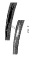
- FIG. 2 contains a digital image showing a portion of a test image whose pixel data have been processed to indicate regions of the test specimen that fall below a predetermined threshold level, and contains a second digital image showing the effect of visually highlighting the low density regions of the first image to assist a technician performing the analysis.
- the highlighting effect can be achieved in a number of ways known in the art of standard image processing techniques. For example, in FIG. 2 a binary mask has been applied to the first image to generate the second image. By highlighting low-density pixel values, it becomes clearer to the technician as to where low density (porous) regions exist within the test specimen, and facilities qualitative and quantitative analysis of the size and location of the void within the test specimen.
- imaging techniques and software can be used to statistically analyze pixel data obtained from the test image and create a summary of pixel data statistics.
- Nonlimiting examples of such statistics include the average and/or mean pixel value, standard deviation value, minimum and maximum pixel values, and the amount of low density regions (below a set threshold) as a percentage of the cross-section of the test specimen analyzed in each CT image.
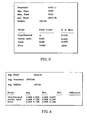
- FIG. 3 represents a software-generated screen displaying statistics based on pixel data obtained from a single CT test image of a test specimen.
- the statistical display includes the average pixel value, standard deviation value, minimum and maximum pixel values, and percentage of the specimen that has low density regions based on differing levels or severity of porosity for the specimen ("Uninfiltrated,” “Partial Infilt.,” and “Total”) for the test specimen.
- the screen shown in FIG. 3 also displays the average pixel value ("Standard") for the reference standard that was scanned with the test specimen.
- the test specimen may have multiple inspection limits for porosity (or other void content) based on attributes such as area, volume, length, density, location or proximity to other porosity regions.
- the method can further include a routine to segregate different regions or zones of the test specimen by applying registration routines specific to the particular test specimen and zones within the specimen that are of particular interest. The routine can then calculate any desired statistics based on pixel data obtained from these zones, and then analyze and compare the data and statistics relative to the inspection limits individually established for each zone.
- the routine described above for each CT image is preferably performed for each image in the stack-up of CT images, enabling the creation of statistical summaries, plots and charts that can highlight areas of interest to a technician.
- Such processing of statistics for an entire test specimen is referred to herein as bulk processing.
- An example of a bulk statistical summary is represented in FIG. 4 , which shows statistical data, including average, maximum, and minimum pixel values and the percentage of low density regions (e.g., below a set threshold) for an entire test specimen.
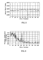
- Examples of bulk statistical plots for mean pixel value and low density percentage of an entire specimen are represented in FIGS. 5 and 6 , respectively.
- the data displayed by the screen of FIG. 4 and the data plotted in the graphs of FIGS. 5 and 6 provide both numerical (quantitative) and visual (qualitative) comparisons to the reference image, whose average pixel value is displayed in FIG. 4 and, if so desired, could be plotted in FIG. 5 .
- the detection and characterization of anomalies within materials may be obtained by performing a three-dimensional imaging scan technique of the test specimen and a reference standard so that a test image and a reference image appear in the scan views.
- the presence of images of both the reference standard and test specimen in each of a plurality of scan views allows for the generation and comparison of data to detect the presence of anomalies throughout the test specimen.
- the method described above provides numerous time-saving opportunities, due in part to the capability for automatic normalization and scaling of data and highlighting of identified low-density regions in a test specimen.
- a system capable of carrying out the steps described above can be adapted from pre-existing CT scanning equipment and pre-existing imaging equipment using known imaging techniques, which are then appropriately controlled with computer-based software to perform the imaging algorithms discussed above, including algorithms for locating the test and reference images in the scan views, normalizing and determining pixel data values in the images, and comparing pixel data values to identify and quantify voids in the test specimen.
- the operation of the equipment and the method as a whole can be tailored to optimize the speed of the NDT analysis.
Landscapes
- Engineering & Computer Science (AREA)
- Theoretical Computer Science (AREA)
- Health & Medical Sciences (AREA)
- Physics & Mathematics (AREA)
- General Physics & Mathematics (AREA)
- Pulmonology (AREA)
- Computer Vision & Pattern Recognition (AREA)
- Nuclear Medicine, Radiotherapy & Molecular Imaging (AREA)
- Quality & Reliability (AREA)
- Radiology & Medical Imaging (AREA)
- Life Sciences & Earth Sciences (AREA)
- Chemical & Material Sciences (AREA)
- Analytical Chemistry (AREA)
- Biochemistry (AREA)
- General Health & Medical Sciences (AREA)
- Immunology (AREA)
- Pathology (AREA)
- Analysing Materials By The Use Of Radiation (AREA)
Applications Claiming Priority (1)
| Application Number | Priority Date | Filing Date | Title |
|---|---|---|---|
| US12/433,168 US8442301B2 (en) | 2009-04-30 | 2009-04-30 | Nondestructive inspection method and system |
Publications (1)
| Publication Number | Publication Date |
|---|---|
| EP2246820A1 true EP2246820A1 (de) | 2010-11-03 |
Family
ID=42545454
Family Applications (1)
| Application Number | Title | Priority Date | Filing Date |
|---|---|---|---|
| EP10154226A Ceased EP2246820A1 (de) | 2009-04-30 | 2010-02-22 | Procédé et système d'inspection non destructive |
Country Status (4)
| Country | Link |
|---|---|
| US (1) | US8442301B2 (de) |
| EP (1) | EP2246820A1 (de) |
| JP (1) | JP2010261933A (de) |
| CA (1) | CA2693468A1 (de) |
Cited By (4)
| Publication number | Priority date | Publication date | Assignee | Title |
|---|---|---|---|---|
| GB2493735A (en) * | 2011-08-17 | 2013-02-20 | Rolls Royce Plc | Method for locating artefacts in a material |
| EP2873966A1 (de) * | 2013-10-30 | 2015-05-20 | General Electric Company | Gasturbinenbauteilüberwachung |
| CN105579834A (zh) * | 2013-09-30 | 2016-05-11 | 株式会社Ihi | 图像分析装置和程序 |
| EP2664915A3 (de) * | 2012-05-17 | 2017-09-06 | Honeywell International Inc. | Zerstörungsfreies Ultraschall-Prüfverfahren für reibgeschweisste Bliske |
Families Citing this family (38)
| Publication number | Priority date | Publication date | Assignee | Title |
|---|---|---|---|---|
| JP2011019135A (ja) * | 2009-07-09 | 2011-01-27 | Sony Corp | 画像受信装置、画像受信方法および画像送信装置 |
| US9298598B2 (en) * | 2010-03-22 | 2016-03-29 | Red Hat, Inc. | Automated visual testing |
| RU2505800C2 (ru) * | 2012-05-10 | 2014-01-27 | Федеральное государственное бюджетное образовательное учреждение высшего профессионального образования "Национальный исследовательский Томский государственный университет" (ТГУ) | Способ рентгеновской томографии и устройство для его осуществления |
| US9002088B2 (en) * | 2012-09-07 | 2015-04-07 | The Boeing Company | Method and apparatus for creating nondestructive inspection porosity standards |
| DE102013001808A1 (de) * | 2013-02-04 | 2014-08-07 | Ge Sensing & Inspection Technologies Gmbh | Verfahren zur zerstörungsfreien Prüfung des Volumens eines Prüflings sowie zur Ausführung eines solchen Verfahrens eingerichtete Prüfvorrichtung |
| EP2962061B1 (de) * | 2013-03-01 | 2017-12-06 | United Technologies Corporation | Blitzthermografiemessung mit doppelter wanddicke |
| WO2015057370A1 (en) * | 2013-10-14 | 2015-04-23 | United Technologies Corporation | Method of detecting conversion quality of green matrix composite material and system for same |
| US9347899B2 (en) | 2013-12-06 | 2016-05-24 | Rolls-Royce Corporation | Thermographic inspection techniques |
| EP3080593B1 (de) | 2013-12-12 | 2021-11-24 | General Electric Company | Verfahren zur defektmeldungsdetektion |
| FR3015035B1 (fr) * | 2013-12-13 | 2016-01-22 | Safran | Mesure non intrusive de la densite volumique d'une phase dans une piece |
| FR3015680B1 (fr) * | 2013-12-19 | 2016-01-15 | Snecma | Procede de caracterisation d'une piece |
| WO2015175202A1 (en) | 2014-05-16 | 2015-11-19 | Halliburton Energy Services, Inc. | Polymer composite wireline cables comprising optical fiber sensors |
| US9557300B2 (en) | 2014-11-12 | 2017-01-31 | Halliburton Energy Services, Inc. | Wireline cable fatigue monitoring using thermally-induced acoustic waves |
| US9557212B2 (en) | 2015-01-06 | 2017-01-31 | Halliburton Energy Services, Inc. | Determining effective elastic modulus of a composite slickline cable |
| US9721334B2 (en) | 2015-12-03 | 2017-08-01 | International Business Machines Corporation | Work-piece defect inspection via optical images and CT images |
| US10181185B2 (en) * | 2016-01-11 | 2019-01-15 | Kla-Tencor Corp. | Image based specimen process control |
| WO2017165191A2 (en) * | 2016-03-23 | 2017-09-28 | The Procter & Gamble Company | Imaging method for determining stray fibers |
| US10410084B2 (en) | 2016-10-26 | 2019-09-10 | Canon Virginia, Inc. | Devices, systems, and methods for anomaly detection |
| US10997712B2 (en) | 2018-01-18 | 2021-05-04 | Canon Virginia, Inc. | Devices, systems, and methods for anchor-point-enabled multi-scale subfield alignment |
| US10997462B2 (en) | 2018-04-04 | 2021-05-04 | Canon Virginia, Inc. | Devices, systems, and methods for clustering reference images for non-destructive testing |
| US10572989B2 (en) * | 2018-06-06 | 2020-02-25 | The Boeing Company | Chopped fiber additive manufacturing void detection |
| US10718724B2 (en) * | 2018-11-06 | 2020-07-21 | Jon M Frenn | Systems and methods of comparative computed tomography (CT) for qualification of commercial grade items |
| US11429806B2 (en) | 2018-11-09 | 2022-08-30 | Canon Virginia, Inc. | Devices, systems, and methods for anomaly detection |
| JP7070995B2 (ja) * | 2018-11-20 | 2022-05-18 | 東芝エネルギーシステムズ株式会社 | 検査方法および検査装置 |
| US11321846B2 (en) | 2019-03-28 | 2022-05-03 | Canon Virginia, Inc. | Devices, systems, and methods for topological normalization for anomaly detection |
| US11237133B2 (en) * | 2019-11-21 | 2022-02-01 | Raytheon Technologies Corporation | Comolded non-destructive inspection standard functioning as a bond bump |
| RU2745304C1 (ru) * | 2020-10-14 | 2021-03-23 | Федеральное государственное автономное образовательное учреждение высшего образования «Национальный исследовательский Томский государственный университет» | Способ рентгеновской томографии и устройство для его осуществления |
| CN113418949B (zh) * | 2020-12-16 | 2024-02-23 | 中航复合材料有限责任公司 | 复合材料x射线测试的标准尺寸样品制备方法及测试方法 |
| US12315176B2 (en) | 2021-04-14 | 2025-05-27 | Canon Virginia, Inc. | Devices, systems, and methods for anomaly detection |
| CN114509454B (zh) * | 2021-12-27 | 2024-11-22 | 江苏西南智能纺织有限公司 | 一种织袜机成品检测系统、存储介质及终端设备 |
| CN114152637B (zh) * | 2022-02-07 | 2022-04-26 | 东莞市志橙半导体材料有限公司 | 一种硬质碳化硅材料打孔检测装置与方法 |
| US12299782B2 (en) | 2022-04-22 | 2025-05-13 | Rtx Corporation | Method and apparatus for analyzing computed tomography data |
| CN114839129B (zh) * | 2022-04-26 | 2024-08-16 | 东华大学 | 一种线上检测方法、装置和系统 |
| US12198257B2 (en) | 2022-08-26 | 2025-01-14 | General Electric Company | System and method of producing a computer-generated image of a component part using computed tomography |
| US12327325B2 (en) * | 2023-02-13 | 2025-06-10 | Rtx Corporation | Method and apparatus for analyzing computed tomography data |
| CN116092012B (zh) * | 2023-03-06 | 2023-06-16 | 安徽数智建造研究院有限公司 | 基于视频流的钢筋绑扎工序监测方法及监测装置 |
| US12320272B2 (en) | 2023-05-09 | 2025-06-03 | General Electric Company | Turbine engine having a composite assembly |
| CN117408510A (zh) * | 2023-10-16 | 2024-01-16 | 国网安徽省电力有限公司铜陵供电公司 | 一种用电数据异常分析方法 |
Citations (4)
| Publication number | Priority date | Publication date | Assignee | Title |
|---|---|---|---|---|
| US5774521A (en) * | 1996-07-08 | 1998-06-30 | Cedars-Sinai Medical Center | Regularization technique for densitometric correction |
| US20050152504A1 (en) | 2004-01-13 | 2005-07-14 | Ang Shih | Method and apparatus for automated tomography inspection |
| US7092484B1 (en) * | 2002-06-14 | 2006-08-15 | Iowa State University Research Foundation, Inc. | Model-assisted reconstruction of volumetric data |
| EP1717573A2 (de) * | 2005-04-29 | 2006-11-02 | YXLON International X-Ray GmbH | Verfahren zur automatischen Fehlererkennung in Prüfteilen mittels einer Röntgenprüfanlage |
Family Cites Families (13)
| Publication number | Priority date | Publication date | Assignee | Title |
|---|---|---|---|---|
| US5015540A (en) * | 1987-06-01 | 1991-05-14 | General Electric Company | Fiber-containing composite |
| CA1274922A (en) * | 1987-09-11 | 1990-10-02 | Terence Taylor | Region of interest tomography employing a differential scanning technique |
| US5330854A (en) * | 1987-09-24 | 1994-07-19 | General Electric Company | Filament-containing composite |
| US5336350A (en) * | 1989-10-31 | 1994-08-09 | General Electric Company | Process for making composite containing fibrous material |
| JP3449561B2 (ja) * | 1993-04-19 | 2003-09-22 | 東芝医用システムエンジニアリング株式会社 | X線ct装置 |
| US5628938A (en) * | 1994-11-18 | 1997-05-13 | General Electric Company | Method of making a ceramic composite by infiltration of a ceramic preform |
| US5850466A (en) * | 1995-02-22 | 1998-12-15 | Cognex Corporation | Golden template comparison for rotated and/or scaled images |
| US6024898A (en) * | 1996-12-30 | 2000-02-15 | General Electric Company | Article and method for making complex shaped preform and silicon carbide composite by melt infiltration |
| US6403158B1 (en) * | 1999-03-05 | 2002-06-11 | General Electric Company | Porous body infiltrating method |
| US6503441B2 (en) * | 2001-05-30 | 2003-01-07 | General Electric Company | Method for producing melt-infiltrated ceramic composites using formed supports |
| US20040067316A1 (en) * | 2002-10-04 | 2004-04-08 | Paul Gray | Method for processing silicon-carbide materials using organic film formers |
| US7417726B2 (en) * | 2003-09-19 | 2008-08-26 | Applied Biosystems Inc. | Normalization of data using controls |
| US20070291277A1 (en) * | 2006-06-20 | 2007-12-20 | Everett Matthew J | Spectral domain optical coherence tomography system |
-
2009
- 2009-04-30 US US12/433,168 patent/US8442301B2/en active Active
-
2010
- 2010-02-18 CA CA2693468A patent/CA2693468A1/en not_active Abandoned
- 2010-02-22 EP EP10154226A patent/EP2246820A1/de not_active Ceased
- 2010-02-26 JP JP2010041191A patent/JP2010261933A/ja not_active Withdrawn
Patent Citations (4)
| Publication number | Priority date | Publication date | Assignee | Title |
|---|---|---|---|---|
| US5774521A (en) * | 1996-07-08 | 1998-06-30 | Cedars-Sinai Medical Center | Regularization technique for densitometric correction |
| US7092484B1 (en) * | 2002-06-14 | 2006-08-15 | Iowa State University Research Foundation, Inc. | Model-assisted reconstruction of volumetric data |
| US20050152504A1 (en) | 2004-01-13 | 2005-07-14 | Ang Shih | Method and apparatus for automated tomography inspection |
| EP1717573A2 (de) * | 2005-04-29 | 2006-11-02 | YXLON International X-Ray GmbH | Verfahren zur automatischen Fehlererkennung in Prüfteilen mittels einer Röntgenprüfanlage |
Non-Patent Citations (3)
| Title |
|---|
| BAUER N ET AL: "DEFEKTE IN WERKSTOFFEN SCHNELL UND EXAKT BESTIMMEN", TECHNISCHE RUNDSCHAU, HALLWAG AG, CH, vol. 84, no. 7, 14 February 1992 (1992-02-14), pages 74 - 76, XP000247709, ISSN: 1023-0823 * |
| MERY D ET AL: "VERFOLGUNG VON GUSSFEHLERN IN EINER DIGITALEN ROENTGENBILDSEQUENZ: EINE NEUE METHODE ZUR AUTOMATISIERUNG DER QUALITAETSKONTROLLE VON GUSSTEILEN FLAW TRACKING IN A SEQUENCE OF DIGITAL X-RAY IMAGES: A NEW METHOD OF AUTOMATED QUALITY CONTROL OF CASTINGS", 1 April 2000, TECHNISCHES MESSEN TM, R.OLDENBOURG VERLAG. MUNCHEN, DE, PAGE(S) 160 - 165, ISSN: 0171-8096, XP000966288 * |
| MORALES-RODRIGUEZ A ET AL: "Porosity analysis of long-fiber-reinforced ceramic matrix composites using X-ray tomography", SCRIPTA MATERIALIA, ELSEVIER, AMSTERDAM, NL LNKD- DOI:10.1016/J.SCRIPTAMAT.2008.11.018, vol. 60, no. 6, 1 March 2009 (2009-03-01), pages 388 - 390, XP025874523, ISSN: 1359-6462, [retrieved on 20081127] * |
Cited By (8)
| Publication number | Priority date | Publication date | Assignee | Title |
|---|---|---|---|---|
| GB2493735A (en) * | 2011-08-17 | 2013-02-20 | Rolls Royce Plc | Method for locating artefacts in a material |
| US8774497B2 (en) | 2011-08-17 | 2014-07-08 | Rolls-Royce Plc | Method for locating artefacts in a material |
| GB2493735B (en) * | 2011-08-17 | 2014-07-23 | Rolls Royce Plc | Method for locating artefacts in a material |
| EP2664915A3 (de) * | 2012-05-17 | 2017-09-06 | Honeywell International Inc. | Zerstörungsfreies Ultraschall-Prüfverfahren für reibgeschweisste Bliske |
| CN105579834A (zh) * | 2013-09-30 | 2016-05-11 | 株式会社Ihi | 图像分析装置和程序 |
| US9811898B2 (en) | 2013-09-30 | 2017-11-07 | Ihi Corporation | Image analyzing apparatus and program |
| CN105579834B (zh) * | 2013-09-30 | 2019-02-19 | 株式会社Ihi | 图像分析装置和程序 |
| EP2873966A1 (de) * | 2013-10-30 | 2015-05-20 | General Electric Company | Gasturbinenbauteilüberwachung |
Also Published As
| Publication number | Publication date |
|---|---|
| US20100278440A1 (en) | 2010-11-04 |
| US8442301B2 (en) | 2013-05-14 |
| JP2010261933A (ja) | 2010-11-18 |
| CA2693468A1 (en) | 2010-10-30 |
Similar Documents
| Publication | Publication Date | Title |
|---|---|---|
| US8442301B2 (en) | Nondestructive inspection method and system | |
| Chowdhury et al. | Damage tolerance of carbon-carbon composites in aerospace application | |
| Jiang et al. | In-situ micro-CT damage analysis of carbon and carbon/glass hybrid laminates under tensile loading by image reconstruction and DVC technology | |
| Lambert et al. | 3D damage characterisation and the role of voids in the fatigue of wind turbine blade materials | |
| Forna-Kreutzer et al. | Full-field characterisation of oxide-oxide ceramic-matrix composites using X-ray computed micro-tomography and digital volume correlation under load at high temperatures | |
| Gao et al. | Identification of microstructures and damages in silicon carbide ceramic matrix composites by deep learning | |
| EP2390074A1 (de) | Inline-Prüfverfahren und Closed-Loop-Verfahren zur Herstellung von Prepegs und/oder Laminaten damit | |
| Goulmy et al. | Characterization of the oxidation of C/C/SiC composites by Xray micro-tomography | |
| Santhosh et al. | Quantification of porosity in ceramic matrix composites using thermography | |
| Dilonardo et al. | Inspection of Carbon Fibre Reinforced Polymers: 3D identification and quantification of components by X-ray CT | |
| Miao et al. | Fatigue and post-fatigue static crack characterisation of a wrinkled thick glass fibre laminate in a composite wind turbine blade | |
| Lakshmi et al. | Overview of NDT methods applied on an aero engine turbine rotor blade | |
| Detwiler et al. | In-situ observation of micro-cracking in a SiC/BN/SiC ceramic matrix composite under tension | |
| Petkov et al. | Thermal oxidative aging of satin weave and thin‐ply polyimide composites | |
| Smith et al. | Electrical resistance changes of melt infiltrated SiC/SiC loaded in tension at room temperature | |
| Yadav et al. | In-line and off-line NDT defect monitoring for thermoplastic automated tape layup | |
| Qu et al. | Microstructure quantitative analysis of multi-scale pores in C/SiC composites via micro-CT for revealing correlations with interlaminar shear properties | |
| Katunin et al. | Evaluation of critical self-heating temperature of composite structures based on analysis of microcrack development | |
| Kim et al. | Nondestructive Evaluation of Microstructure of SiC f/SiC Composites by X-Ray Computed Microtomography | |
| Wen et al. | Detection and characterization method for interface bonding defects of new composite materials | |
| Leone et al. | Investigating transverse ply thickness and cracking effects on the tensile strain to failure of thin-ply, cross-ply carbon composites using X-ray computed tomography | |
| Chen et al. | In Situ X‐Ray Tomography and Acoustic Emission Monitoring of Damage Evolution in C/C‐SiC Composites Fabricated by Liquid Silicon Infiltration | |
| Zhang et al. | 4D damage evolution in SiCf/SiC composites at 1800° C: A quantitative study of pores and strain fields by in-situ μCT and DVC | |
| Abdul-Aziz et al. | Combined NDE/finite element technique to study the effects of matrix porosity in the behavior of ceramic matrix composites | |
| Ferreira et al. | MicroCT-Based Methodology for Defect Detection and Analysis in GRFP Tube Joints |
Legal Events
| Date | Code | Title | Description |
|---|---|---|---|
| PUAI | Public reference made under article 153(3) epc to a published international application that has entered the european phase |
Free format text: ORIGINAL CODE: 0009012 |
|
| AK | Designated contracting states |
Kind code of ref document: A1 Designated state(s): AT BE BG CH CY CZ DE DK EE ES FI FR GB GR HR HU IE IS IT LI LT LU LV MC MK MT NL NO PL PT RO SE SI SK SM TR |
|
| AX | Request for extension of the european patent |
Extension state: AL BA RS |
|
| 17P | Request for examination filed |
Effective date: 20110503 |
|
| 17Q | First examination report despatched |
Effective date: 20120118 |
|
| STAA | Information on the status of an ep patent application or granted ep patent |
Free format text: STATUS: THE APPLICATION HAS BEEN REFUSED |
|
| 18R | Application refused |
Effective date: 20130306 |