EP2246959A1 - Appareil ménager doté d'un dispositif de commutation et procédé correspondant - Google Patents
Appareil ménager doté d'un dispositif de commutation et procédé correspondant Download PDFInfo
- Publication number
- EP2246959A1 EP2246959A1 EP10157036A EP10157036A EP2246959A1 EP 2246959 A1 EP2246959 A1 EP 2246959A1 EP 10157036 A EP10157036 A EP 10157036A EP 10157036 A EP10157036 A EP 10157036A EP 2246959 A1 EP2246959 A1 EP 2246959A1
- Authority
- EP
- European Patent Office
- Prior art keywords
- operating voltage
- voltage
- value
- operating
- zener diode
- Prior art date
- Legal status (The legal status is an assumption and is not a legal conclusion. Google has not performed a legal analysis and makes no representation as to the accuracy of the status listed.)
- Withdrawn
Links
Images
Classifications
-
- H—ELECTRICITY
- H02—GENERATION; CONVERSION OR DISTRIBUTION OF ELECTRIC POWER
- H02J—ELECTRIC POWER NETWORKS; CIRCUIT ARRANGEMENTS OR SYSTEMS FOR SUPPLYING OR DISTRIBUTING ELECTRIC POWER; SYSTEMS FOR STORING ELECTRIC ENERGY
- H02J9/00—Circuit arrangements for emergency or stand-by power supply, e.g. for emergency lighting
- H02J9/005—Circuit arrangements for emergency or stand-by power supply, e.g. for emergency lighting using a power saving mode
Definitions
- the invention relates to a household appliance with a circuit arrangement of the type specified in the preamble of claim 1.
- the invention further relates to a corresponding method.
- electrical devices can be switched over between an active state and a waiting state that is reduced in energy consumption compared with the active state (also known as "stand-by").
- a waiting state that is reduced in energy consumption compared with the active state (also known as "stand-by").
- a circuit arrangement for remote-controlled television sets known, which allows the switching of such a device between the active state and the waiting state.
- the washing machine may be switched between an active state in which a power supply supplies the required power to the washing machine and a wait state in which the power supply is turned off.
- the publication JP 2005 027 354 A describes a circuit arrangement for a television receiver or an air conditioner.
- This circuit arrangement includes a power supply, which provides a first DC voltage from a mains voltage.
- a voltage converter converts the first DC voltage to a second DC voltage that is less than the first DC voltage.
- the second DC voltage is supplied to a microcontroller.
- the first DC voltage supplies a large number of electrical consumers.
- the amplitude of the first DC voltage can be influenced by means of an optocoupler. Namely, an opto-transistor of the optocoupler is connected to a control input of the power supply, while the light-emitting diode of the optocoupler is coupled on the one hand to the output of the power supply and on the other hand with a controllable diode.
- a voltage divider with three resistors picks up the first DC voltage and divides it, so that the divided voltage is applied to the control input of the controllable diode.
- One of the resistors of the voltage divider can optionally be switched on, and the amplitude of the divided voltage can thus be changed.
- the controllable diode optionally has two different breakdown voltages, and optionally different amplitudes of the first DC voltage can be set.
- a circuit arrangement for operating a screen device is from the document US 5,920,466 A known.
- An inventive household appliance comprises a circuit arrangement which is designed for operating a household appliance.
- the circuit arrangement comprises a circuit input for applying an alternating supply voltage. Connected to the circuit input is a switching power supply for providing a first DC operating voltage between a circuit pole and a reference potential. At least one first electrical consumer can be supplied with the first DC operating voltage.
- the circuit arrangement comprises a voltage converter coupled to the circuit pole for providing a second operating DC voltage for at least one second electrical load, wherein the second DC operating voltage is lower in value than the first DC operating voltage.
- a controller is configured to switch the circuitry between an active state and a wait state. There are provided means for setting the first DC operating voltage, which set the first DC operating voltage to a first value in the active state of the circuit arrangement and lower the first DC operating voltage from the first value to a second value when switching to the waiting state.
- the invention is thus based on the recognition that in a circuit arrangement in which initially a first DC operating voltage and then a lower second DC operating voltage are provided, most of the energy losses in the conversion of the first DC operating voltage to the second DC operating voltage arise. These losses can be reduced to a minimum in the waiting operation when the first operating DC voltage is lowered to a second value.
- the invention makes use of the fact that the one electrical consumer, which is supplied with the first DC operating voltage, is not put into operation in the waiting state, that is, does not have to be controlled.
- the control device can wait for inputs from an operator in the waiting state and, after receiving a predetermined input, increase the first operating DC voltage back to the first value, then the first electrical load can also be supplied.
- the means for setting the first DC operating voltage are coupled to a control terminal of the switching power supply and thus intervene in a control loop of the switching power supply. Then, the means for setting the first DC operating voltage can transmit a reference variable to the control terminal of the switching power supply, and the switching power supply can then control the first DC operating voltage depending on this reference variable.
- the reference variable is preferably correlated with a desired value for the first DC operating voltage or represents this desired value.
- the means for setting the first DC operating voltage engage in the control loop of the switched-mode power supply. The first DC operating voltage can thus be set without much effort by simply transmitting the reference variable to the control terminal of the switching power supply.
- the means for setting the first DC operating voltage comprise an optocoupler whose transistor is coupled to the control terminal of the switched-mode power supply and whose diode is coupled on the one hand to the circuit pole and on the other hand via a first Zener diode to the reference potential.
- a second Zener diode is switchable parallel to the first Zener diode.
- the first Zener diode then has such a breakdown voltage, which is tuned to the first value of the first DC operating voltage
- the second Zener diode has such a breakdown voltage, which is tuned to the second value of the first DC operating voltage. Accordingly, the reference variable is transmitted via the optocoupler to the control terminal of the switching power supply.
- the first Zener diode In the active state, that is, when the first DC operating voltage is set to the first value, the first Zener diode is connected in series with the diode of the opto-coupler, the first value of the first DC operating voltage is the sum of the breakdown voltage of the first Zener diode and the falling across the diode of the optocoupler Voltage then flow between the circuit pole and the reference potential, that is, via the series connection of the first zener diode and the diode of the optocoupler, very low currents. If now the second Zener diode is connected in parallel to the first Zener diode, it bridges the first Zener diode, and current flows through the second Zener diode and thus also via the diode of the optocoupler.
- This current is caused by the voltage drop since the second Zener diode has a lower breakdown voltage than the first Zener diode.
- the current flowing through the diode of the optocoupler then causes the diode of the optocoupler to shine, and the optocoupler transistor is driven.
- the switching power supply receives feedback from the transistor and begins to reduce the first DC operating voltage to the second value.
- the transistor thus transmits the reference variable to the control connection of the switched-mode power supply. In this way, it is possible to intervene in the control loop of the switching power supply by using only one optocoupler and two zener diodes.
- a household appliance is a device that is used for household management. This may be a large household appliance, such as a washing machine, a tumble dryer, a dishwasher, a cooking appliance, a cooker hood, a refrigerator, aissergefrierkombination or an air conditioner. But this can also be a small household appliance, such as a coffee machine or a food processor.
- the first and the second DC operating voltage are in particular DC voltages which are in a value range up to 20 volts.
- the second DC operating voltage is always lower than the first DC operating voltage.
- the second operating DC voltage can be in a value range between 2 and 9 volts, it is preferably 5 or 3.3 volts.
- the second value of the first DC operating voltage is preferably between the second DC operating voltage and the first value of the first DC operating voltage.
- the second value of the first DC operating voltage may be, for example, 0.1 volt to 1 volt higher than the second DC operating voltage.
- the first value of the first operating DC voltage is in particular in a value range between 5 and 15 volts, it is preferably 9 or 12 volts.
- the second zener diode can be switched particularly easily in parallel to the first zener diode when it is coupled in series with an electrical switch.
- the control device can then close the electrical switch and thus convert the circuit arrangement into the waiting state.
- the voltage converter is a buck converter, it sets the first DC operating voltage in the second DC operating voltage down.
- the voltage converter can be, for example, a voltage regulator, in particular a series regulator.
- the second DC operating voltage can be stabilized and thus kept constant, namely, regardless of whether the circuit arrangement is in the active state or in the waiting state.
- a voltage regulator it is possible to set a constant second DC operating voltage independently of the respective instantaneous value of the first DC operating voltage.
- an input signal can be generated by means of the operating device and transmitted to the control device.
- the input signal then causes the switching of the circuit arrangement between the active state and the waiting state.
- This can for example, such that an operator makes a predetermined input to the operating device, for example, operates a predetermined operating element, and the operating device then generates the input signal and transmits it to the control device.
- the control device then transfers the circuit arrangement to the selected state, that is, to the waiting or active state. An operator can thus initiate the transfer of the circuit between the active state and the waiting state.
- the control device evaluates a clock signal (clock) and, depending on this evaluation, effects the transfer of the circuit arrangement between the active state and the wait state. This may be done, for example, such that the controller transfers the circuitry from the active state to the wait state when no input is made by an operator over a predetermined time interval, i. when the controller receives no input signals from an operator over the predetermined time interval. This can also be such that an operator sets a program of the household appliance, which should start after a preselected time. Then, after selecting the program, the control device can put the circuit arrangement in the wait state and switch it back to the active state immediately before the start of the program. In this embodiment, the control device thus controls the switching between the active state and the waiting state "self" and depending on the time.
- clock clock
- the invention also includes a household appliance, which comprises a circuit arrangement according to the invention or a preferred embodiment thereof.
- an AC supply voltage is provided at a circuit input of a circuit arrangement. From the AC supply voltage, a first DC operating voltage between a circuit pole and a reference potential is provided by a switching power supply. At least one first electrical consumer is supplied with the first DC operating voltage. From the first DC operating voltage, a voltage converter provides a second DC operating voltage for at least one second electrical load, wherein the second DC operating voltage in terms of value is lower than the first DC operating voltage. There is a switching of the circuit arrangement between an active state and a waiting state by means of a control device. In this case, the first operating DC voltage is set to a first value in the active state and reduced from the first value to a second value when switching to the wait state.
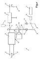
- a circuit arrangement shown in the figure and denoted overall by 1 is used to operate a household appliance, in this case for example a washing machine, and comprises a circuit input 2 with a first and a second input terminal 3, 4. At the circuit input 2 is an AC supply voltage U N , namely between the input terminals 3, 4. The switching input 2, a switching power supply 5 is coupled, which converts the AC supply voltage U N in a first DC operating voltage U 1 .
- a first group 6 can be supplied by electrical consumers, namely in particular actuators and sensors of the washing machine.
- the first DC operating voltage U 1 is provided between a circuit pole 7 and a reference potential 8.
- a series regulator 9 is coupled, which converts the first DC operating voltage U 1 into a second DC operating voltage U 2 .
- the second DC operating voltage U 2 is in terms of value lower than the first DC operating voltage U 1 , the longitudinal regulator 9 serves to downshift the first DC operating voltage U. 1
- the second DC operating voltage U 2 lies between an output terminal 10 and the reference potential 8.
- a control device 11 is supplied, namely, for example, a microprocessor or a comparable drive circuit.
- the control device 11 can transfer the circuit arrangement 1 between an active state and a wait state. Namely, there arise 2 losses caused by the series regulator 9 in the conversion of the first DC operating voltage U 1 in the second operating DC voltage U. It is true that the greater the difference between the first DC operating voltage U 1 and the second DC operating voltage U 2 , the higher the losses.
- the first group 6 of electrical loads for example, 9 volts (may also be 12 volts)
- the difference between the two voltages is 4 volts, and the losses are correspondingly large.
- the optocoupler 12 includes a diode 15 which optically drives a transistor 16.
- the anode of the diode 15 is coupled to the circuit pole 7, and the cathode of the diode 15 is coupled to a pole 20.
- the pole 20 is coupled both to the cathode of the first Zener diode 13 and to the cathode of the second Zener diode 14.
- the anode of the first Zener diode 13 is located at the reference potential 8.
- the anode of the second Zener diode 14 can be coupled via an electrical switch 17 to the reference potential 8.
- the electrical switch 17 may be a relay or a transistor.
- the electrical switch 17 can be controlled via a driver 18 by the controller 11, that is closed or opened.
- the electrical switch 17 is opened, that is to say the second Zener diode 14 is decoupled from the reference potential 8 and thus has no influence on the first operating direct voltage U 1 .
- the control device 11 closes the electrical switch 17. Then flows via the diode 15 and the second Zener diode 14 electric current of high amperage.
- the current flowing after closing the electrical switch 17 is detected by the switching power supply 5, for this purpose, the transistor 16 of the optocoupler 12 with a control terminal 19 of the switching power supply 5 coupled. If current flows through the diode 15 of the optocoupler 12, the transistor 16 is optically controlled by the diode 15 and transmits to the switching power supply a reference variable, so that the switching power supply 5 receives feedback via the control connection 19. Then, the switched-mode power supply 5 begins to regulate the DC operating voltage U 1 to the second value, that is to say 6 volts (4 volts from the first Zener diode 14 + 2 volts from the diode 15). The switching power supply 5 thus takes over the control of the first DC operating voltage U 1 to the second value after closing the electrical switch 17th
- a command is transmitted to the control terminal 19 of the power supply that sets the first DC operating voltage U. 1
- the electrical current flowing through the diode 15 can essentially have three different current strengths, namely a first negligible current intensity, a low current intensity and a high current intensity. If the switch 17 is opened, that is to say the circuit arrangement 1 is in the active state, a current of low current flows through the diode 15. If the switch 17 is closed, the current intensity of this current is high, and the switching power supply begins to reduce the first DC operating voltage U 1 . If the switch 17 is opened again, then the current intensity of the current is negligible, so that the switching power supply 5 begins to increase the first DC operating voltage U 1 .
- a circuit arrangement 1 is altogether provided in which the losses caused by the series regulator 9 can be reduced to a minimum in the waiting state.
- This is achieved by the first DC operating voltage U 1 is reduced from a higher first value of eg 9 volts to a second lower value of eg 6 volts, wherein the second value of the first DC operating voltage even higher than the second DC operating voltage U 2 is.
- the control device 11 which controls the switching of the circuit arrangement 1 between the active state and the waiting state.
Landscapes
- Business, Economics & Management (AREA)
- Emergency Management (AREA)
- Engineering & Computer Science (AREA)
- Power Engineering (AREA)
- Dc-Dc Converters (AREA)
- Rectifiers (AREA)
Applications Claiming Priority (1)
| Application Number | Priority Date | Filing Date | Title |
|---|---|---|---|
| DE200910002271 DE102009002271A1 (de) | 2009-04-07 | 2009-04-07 | Schaltungsanordnung zum Betreiben eines Haushaltsgeräts und entsprechendes Verfahren |
Publications (1)
| Publication Number | Publication Date |
|---|---|
| EP2246959A1 true EP2246959A1 (fr) | 2010-11-03 |
Family
ID=42697460
Family Applications (1)
| Application Number | Title | Priority Date | Filing Date |
|---|---|---|---|
| EP10157036A Withdrawn EP2246959A1 (fr) | 2009-04-07 | 2010-03-19 | Appareil ménager doté d'un dispositif de commutation et procédé correspondant |
Country Status (2)
| Country | Link |
|---|---|
| EP (1) | EP2246959A1 (fr) |
| DE (1) | DE102009002271A1 (fr) |
Cited By (2)
| Publication number | Priority date | Publication date | Assignee | Title |
|---|---|---|---|---|
| ITPD20110399A1 (it) * | 2011-12-19 | 2013-06-20 | Ln 2 Srl Socio Unico | Gruppo di aspirazione per cappa |
| CN103618537A (zh) * | 2013-12-11 | 2014-03-05 | 济南诺辉节能技术开发有限公司 | 高压信号转换电路 |
Families Citing this family (1)
| Publication number | Priority date | Publication date | Assignee | Title |
|---|---|---|---|---|
| DE102011117609A1 (de) * | 2011-11-04 | 2013-05-08 | Arca Beteiligungen Gmbh | Steuerungsanordnung |
Citations (6)
| Publication number | Priority date | Publication date | Assignee | Title |
|---|---|---|---|---|
| JPH11162691A (ja) | 1997-11-27 | 1999-06-18 | Toshiba Tec Corp | 放電灯点灯装置 |
| US5920466A (en) | 1996-06-29 | 1999-07-06 | Matsushita Electric Industrial Co., Ltd. | Switching power supply unit |
| EP1058374A1 (fr) * | 1999-06-01 | 2000-12-06 | Motorola, Inc. | Dispositif de contrôle par modulation à largeur d'impulsions |
| DE20014724U1 (de) * | 2000-08-25 | 2000-12-14 | Will, Elmar H., 84036 Landshut | Schaltungsanordnung zur Verringerung der Leistungsaufnahme elektronischer Geräte im Standby-Betrieb |
| JP2005027354A (ja) * | 2004-10-04 | 2005-01-27 | Mitsubishi Electric Corp | 電源制御装置 |
| WO2006120640A2 (fr) * | 2005-05-10 | 2006-11-16 | Nxp B.V. | Technique de transmission a retroaction pour alimentation electrique en mode commute |
Family Cites Families (2)
| Publication number | Priority date | Publication date | Assignee | Title |
|---|---|---|---|---|
| DE4421869A1 (de) | 1994-06-23 | 1996-01-04 | Nokia Deutschland Gmbh | Schaltungsanordnung für den Wartebetrieb eines fernbedienbaren Gerätes |
| KR101158060B1 (ko) | 2005-07-01 | 2012-06-18 | 엘지전자 주식회사 | 세탁기의 대기전력 제어장치 및 그 방법 |
-
2009
- 2009-04-07 DE DE200910002271 patent/DE102009002271A1/de not_active Withdrawn
-
2010
- 2010-03-19 EP EP10157036A patent/EP2246959A1/fr not_active Withdrawn
Patent Citations (6)
| Publication number | Priority date | Publication date | Assignee | Title |
|---|---|---|---|---|
| US5920466A (en) | 1996-06-29 | 1999-07-06 | Matsushita Electric Industrial Co., Ltd. | Switching power supply unit |
| JPH11162691A (ja) | 1997-11-27 | 1999-06-18 | Toshiba Tec Corp | 放電灯点灯装置 |
| EP1058374A1 (fr) * | 1999-06-01 | 2000-12-06 | Motorola, Inc. | Dispositif de contrôle par modulation à largeur d'impulsions |
| DE20014724U1 (de) * | 2000-08-25 | 2000-12-14 | Will, Elmar H., 84036 Landshut | Schaltungsanordnung zur Verringerung der Leistungsaufnahme elektronischer Geräte im Standby-Betrieb |
| JP2005027354A (ja) * | 2004-10-04 | 2005-01-27 | Mitsubishi Electric Corp | 電源制御装置 |
| WO2006120640A2 (fr) * | 2005-05-10 | 2006-11-16 | Nxp B.V. | Technique de transmission a retroaction pour alimentation electrique en mode commute |
Non-Patent Citations (1)
| Title |
|---|
| CYR, NICOLAS: "AND8145/D A 75 W TV Power Supply Operating in Quasi-square Wave Resonant Mode using the NCP1207 Controller", 31 March 2004 (2004-03-31), XP002601087, Retrieved from the Internet <URL:http://www.onsemi.com/pub_link/Collateral/AND8145-D.PDF> [retrieved on 20100915] * |
Cited By (2)
| Publication number | Priority date | Publication date | Assignee | Title |
|---|---|---|---|---|
| ITPD20110399A1 (it) * | 2011-12-19 | 2013-06-20 | Ln 2 Srl Socio Unico | Gruppo di aspirazione per cappa |
| CN103618537A (zh) * | 2013-12-11 | 2014-03-05 | 济南诺辉节能技术开发有限公司 | 高压信号转换电路 |
Also Published As
| Publication number | Publication date |
|---|---|
| DE102009002271A1 (de) | 2010-10-14 |
Similar Documents
| Publication | Publication Date | Title |
|---|---|---|
| EP2373839B1 (fr) | Appareil electro-menager avec dispositiv d'arret automatique | |
| EP1602169A2 (fr) | Circuit d'excitation pour alimentation a decoupage | |
| DE10356515A1 (de) | Antriebssystem | |
| DE102007058379A1 (de) | Schaltungsanordnung zum Betreiben eines Hausgeräts | |
| EP2512207B1 (fr) | Circuit d'excitation et procédé d'alimentation d'une DEL ainsi que moyen d'éclairage | |
| EP2315338B1 (fr) | Agencement de commutation (à l'arrêt) destiné au fonctionnement d'un appareil ménager et procédé correspondant | |
| DE102009002271A1 (de) | Schaltungsanordnung zum Betreiben eines Haushaltsgeräts und entsprechendes Verfahren | |
| EP2315337B1 (fr) | Appareil ménager et procédé de fonctionnement d'un appareil ménager | |
| EP2385608B1 (fr) | Entraînement de meuble électro-motorisé doté d'un dispositif d'alimentation en énergie | |
| EP3043461B1 (fr) | Circuit d'alimentation d'un appareil de soudage | |
| EP2229719B1 (fr) | Circuiterie permettant de faire fonctionner un appareil ménager | |
| EP3363036B1 (fr) | Dispositif de commande pour un entraînement électromagnétique d'un appareil de commutation | |
| DE102014219787A1 (de) | Schaltnetzteil mit zumindest einem Leistungsteil und zumindest einem Hilfsnetzteil | |
| EP3467610B1 (fr) | Thermostat d'ambiance électronique à deux fils | |
| EP2009777A2 (fr) | Alimentation régulée en modulation de largeur d'impulsion | |
| DE102012204224A1 (de) | Haushaltsgerät mit einer Lambda-Sonde bzw. Verfahren zum Betreiben eines Haushaltsgeräts mit einer Lambda-Sonde | |
| EP3836344A1 (fr) | Agencement comportant un consommateur électrique pourvu de convertisseur continu-continu | |
| EP2684276B1 (fr) | Appareil ménager ayant un mode de veille ainsi que procédé pour faire fonctionner un tel appareil ménager | |
| EP1609236B1 (fr) | Procede et unite de commande pour commander des moteurs ventiles | |
| DE102010016157A1 (de) | Verfahren zum Betreiben eines elektrischen Verbrauchers sowie Anordnung umfassend ein Schaltnetzteil und einen elektrischen Verbraucher sowie Schaltnetzteil und elektrischer Verbraucher | |
| DE102008016472A1 (de) | Schaltungsanordnung zum Betreiben einer elektrischen Maschine eines Hausgeräts und entsprechendes Verfahren | |
| DE69112283T2 (de) | Elektrisches System mit einem elektromechanischen Relais und einem Gleichrichter-Reduktor-Schaltkreis. | |
| WO2024251622A1 (fr) | Dispositif de commande, système dynamique d'entraînement et véhicule à moteur | |
| DE102014209113A1 (de) | Verriegelungseinrichtung zum Verriegeln einer Tür eines Haushaltsgeräts, Haushaltsgerät und entsprechendes Verfahren | |
| EP2212988A1 (fr) | Procédé pour identifier l'actionnement d'un élément de commande d'un panneau de commande d'un convertisseur, et panneau de commande pour un convertisseur |
Legal Events
| Date | Code | Title | Description |
|---|---|---|---|
| PUAI | Public reference made under article 153(3) epc to a published international application that has entered the european phase |
Free format text: ORIGINAL CODE: 0009012 |
|
| AK | Designated contracting states |
Kind code of ref document: A1 Designated state(s): AT BE BG CH CY CZ DE DK EE ES FI FR GB GR HR HU IE IS IT LI LT LU LV MC MK MT NL NO PL PT RO SE SI SK SM TR |
|
| AX | Request for extension of the european patent |
Extension state: AL BA ME RS |
|
| 17P | Request for examination filed |
Effective date: 20110503 |
|
| 17Q | First examination report despatched |
Effective date: 20130107 |
|
| RAP1 | Party data changed (applicant data changed or rights of an application transferred) |
Owner name: BSH HAUSGERAETE GMBH |
|
| STAA | Information on the status of an ep patent application or granted ep patent |
Free format text: STATUS: THE APPLICATION IS DEEMED TO BE WITHDRAWN |
|
| 18D | Application deemed to be withdrawn |
Effective date: 20180104 |