EP2247507B1 - SYSTEM ZUM NACHFÜLLEN VON FLIEß- ODER SCHÜTTFÄHIGEN WASCH- ODER REINIGUNGSMITTELN - Google Patents
SYSTEM ZUM NACHFÜLLEN VON FLIEß- ODER SCHÜTTFÄHIGEN WASCH- ODER REINIGUNGSMITTELN Download PDFInfo
- Publication number
- EP2247507B1 EP2247507B1 EP08805082.8A EP08805082A EP2247507B1 EP 2247507 B1 EP2247507 B1 EP 2247507B1 EP 08805082 A EP08805082 A EP 08805082A EP 2247507 B1 EP2247507 B1 EP 2247507B1
- Authority
- EP
- European Patent Office
- Prior art keywords
- funnel
- flowable
- cleaning agents
- pourer
- refilling
- Prior art date
- Legal status (The legal status is an assumption and is not a legal conclusion. Google has not performed a legal analysis and makes no representation as to the accuracy of the status listed.)
- Active
Links
Images


Classifications
-
- B—PERFORMING OPERATIONS; TRANSPORTING
- B67—OPENING, CLOSING OR CLEANING BOTTLES, JARS OR SIMILAR CONTAINERS; LIQUID HANDLING
- B67C—CLEANING, FILLING WITH LIQUIDS OR SEMILIQUIDS, OR EMPTYING, OF BOTTLES, JARS, CANS, CASKS, BARRELS, OR SIMILAR CONTAINERS, NOT OTHERWISE PROVIDED FOR; FUNNELS
- B67C9/00—Devices for emptying bottles, not otherwise provided for
-
- B—PERFORMING OPERATIONS; TRANSPORTING
- B65—CONVEYING; PACKING; STORING; HANDLING THIN OR FILAMENTARY MATERIAL
- B65D—CONTAINERS FOR STORAGE OR TRANSPORT OF ARTICLES OR MATERIALS, e.g. BAGS, BARRELS, BOTTLES, BOXES, CANS, CARTONS, CRATES, DRUMS, JARS, TANKS, HOPPERS, FORWARDING CONTAINERS; ACCESSORIES, CLOSURES, OR FITTINGS THEREFOR; PACKAGING ELEMENTS; PACKAGES
- B65D47/00—Closures with filling and discharging, or with discharging, devices
- B65D47/04—Closures with discharging devices other than pumps
- B65D47/06—Closures with discharging devices other than pumps with pouring spouts or tubes; with discharge nozzles or passages
-
- B—PERFORMING OPERATIONS; TRANSPORTING
- B65—CONVEYING; PACKING; STORING; HANDLING THIN OR FILAMENTARY MATERIAL
- B65D—CONTAINERS FOR STORAGE OR TRANSPORT OF ARTICLES OR MATERIALS, e.g. BAGS, BARRELS, BOTTLES, BOXES, CANS, CARTONS, CRATES, DRUMS, JARS, TANKS, HOPPERS, FORWARDING CONTAINERS; ACCESSORIES, CLOSURES, OR FITTINGS THEREFOR; PACKAGING ELEMENTS; PACKAGES
- B65D47/00—Closures with filling and discharging, or with discharging, devices
- B65D47/04—Closures with discharging devices other than pumps
- B65D47/06—Closures with discharging devices other than pumps with pouring spouts or tubes; with discharge nozzles or passages
- B65D47/10—Closures with discharging devices other than pumps with pouring spouts or tubes; with discharge nozzles or passages having frangible closures
-
- B—PERFORMING OPERATIONS; TRANSPORTING
- B67—OPENING, CLOSING OR CLEANING BOTTLES, JARS OR SIMILAR CONTAINERS; LIQUID HANDLING
- B67B—APPLYING CLOSURE MEMBERS TO BOTTLES JARS, OR SIMILAR CONTAINERS; OPENING CLOSED CONTAINERS
- B67B7/00—Hand- or power-operated devices for opening closed containers
- B67B7/24—Hole-piercing devices
- B67B7/26—Hole-piercing devices combined with spouts
- B67B7/28—Hole-piercing devices combined with spouts and associated with receptacle hodlers
Definitions
- the invention relates to a system for refilling flowable or pourable detergents or cleaners from a refill container into a bottle provided with a spout according to the preamble of claim 1.
- Such systems have the advantage that the transport packaging is usually manufactured with less material and processing costs, so that it brings significant savings in raw materials and resulting cost and environmental advantages over the storage containers.
- a generic refill system that consists of a pourable on a bottle spout to which a refill container can be coupled in such a way that the spout when placing the refill on the spout pierces the sealing film that closes the opening of the refill container, and so on the content of the refill container flows into the bottle.
- a major disadvantage of this solution is that the sealing film for closing the refill container must be so thin that it can still be pierced with a reasonable force when placing the refill on the spout. As a result, there is a risk that such a film is accidentally damaged during transport and so the contents of the refill container unintentionally pours. This can happen, in particular, when a consumer places such a refill container in a shopping trolley or grocery bag with other products, wherein in particular the corners of a product package or slim-shaped products such as pins can destroy the sealing film of the refill container with unavoidable relative movements between the goods thus transported.
- an additional closure cap for protecting the film against mechanical influences is conceivable in principle, such an additional component makes a refill container, which is as cost-effective as possible, appreciably more expensive. Furthermore, an additional cap in addition to the production of the component also requires - by the necessary screwing or bouncing - an additional assembly step in the packaging of a corresponding refill container.
- any refill container can be coupled with a specific storage container, for example, when non-storage-stable products are inadvertently mixed together by a refilling process.
- the object of the invention is therefore to provide a system for refilling flowable or pourable detergents or cleaners from a refill container sealed with a membrane into a bottle provided with a spout, in which the film of the refill container is protected in a cost-effective manner against mechanical effects, can be penetrated in a conventional manner with a reasonable force through the spout and prevents inadvertent refilling of non-intermingled products.
- the inventive system for refilling flowable or pourable detergents or cleaning agents achieves the result described above with a structurally very simple and easy to handle solution, in particular by the formation of a "key lock" principle and an exact guidance and relative positioning in the Coupling of adapter element and spout, which will be explained in more detail below.
- the system according to the invention for refilling a pourable or flowable washing or cleaning agent comprises, in addition to the bottle provided with a spout described in more detail below, a refilling container at the pouring opening of which an adapter element is arranged.
- the adapter element has the task to couple the refill container with the spout so that the contents of the refill container safely from the refill container, passes through the spout into the bottle.
- the adapter element is provided with a fastening means for liquid-tight attachment to a refill, that adapter element can be connected to any shaped refill containers.
- the attachment between the refill and the Adapter element can be detachable or non-detachable material, form or force fit.
- the fastening element is designed as a screw connection, bounce connection, snap-locking connection, adhesive connection or a combination thereof.
- the adapter is preferably made of a plastic material, in particular by an injection molding process.
- the adapter further comprises a cylindrical element and a circumferential collar connected to the cylinder element.
- the projection of the cylinder element preferably results in a circular or oval contour.
- the cylinder element is therefore not limited to a circular or oval projection contour.
- the cylinder element further has a guide groove which is configured in such a way that the cylinder element can be detachably placed over the funnel and a protruding from the funnel plane web of the spout, whereby the positioning of the adapter element is fixed relative to the spout.
- the adapter element is slipped over the funnel of the spout according to a key-lock principle.
- the formation of such a key-lock principle has a number of advantages. On the one hand, it is ensured that only refill containers provided with a corresponding adapter can be coupled to the spout. This can be prevented from causing unwanted mixing of e.g. detergent compositions which are not storable with one another if, for example, there is still a residual amount of a first detergent composition in the bottle, but this is to be filled with a second detergent composition before complete emptying.
- the positioning of the adapter element relative to the spout is determined by the guide groove and the web when the adapter is coupled to the spout. For example, turning the adapter in the coupled state is prevented.
- convenient dome operation can therefore be provided at such a defined and predetermined penetration one or more thin spots in the membrane.
- the spout acts in addition to its generic function as pouring at the same time as an opening aid for the membrane of the adapter, so that can be dispensed with an additional opening aid.
- At least one ramp-shaped guide rib is arranged on the inside of the cylinder element from the pouring opening of the cylinder element towards the membrane.
- the adapter elements in such a way that the guide groove terminates at a distance from the pouring edge of the cylinder element and a substantially V-shaped opening extends from the guide groove to the pouring edge of the cylinder element.
- the slipping over of the adapter element is simplified via the funnel, since the web is automatically guided by the V-shaped opening during the coupling process in the guide groove.
- the V-shaped opening a certain misalignment in the positioning of guide groove to bridge in the coupling process is compensated.
- the refill container can be designed both as a dimensionally stable container, in particular as a bottle, can, carton or the like, and as a flexible container, such as something as a bag or tube.
- the refill container has a lower average wall thickness than the bottle into which the content of the refill container is to be filled.
- the refill container is made of a plastic material.
- a flat closure element understood that mounted in the refill container state of the adapter element, the adapter element closes the refill and leakage of flowable or pourable detergents or cleaning agents from the refill container, especially in the over-head Position of the refill container, prevented and pierceable when coupling the adapter element with the spout by a user from the funnel of the spout.
- the membrane may be formed integrally with the adapter element or be arranged as a separate part on the adapter element, preferably cohesively.
- the membrane is advantageously formed from a plastic, such as PE, PP, PET or a metal, such as aluminum.
- the thickness of the membrane is between 0.3 .mu.m and 1.5 .mu.m, preferably between 0.5 .mu.m and 1 .mu.m.
- Thin sites in the sense of these applications are material weakenings of the membrane, which are formed in particular by a reduction of the material thickness.
- the membrane has one or more thin locations that at least partially correspond to the projection of the funnel shape of the spout.
- the projection of the funnel molding is a round or oval contour and at least one thin spot is linear and follows this contour at least partially in such a way that when coupling adapter element with the spout of the funnel abuts the thin point.
- a further, particularly preferred embodiment of the invention has the thin spot a substantially T-shaped portion which is configured in such a way that it comes to the top of the funnel when coupling adapter element with the spout.
- the spout is a liquid-tight attachable to the pouring opening of a bottle device for the controlled and convenient dispensing of free-flowing or pourable detergents or cleaning agents from the bottle, in particular by tilting the bottle from a stand to a dispensing position.
- Such spouts are also known as "spouts”.
- the spout is fixed in a liquid-tight manner to the spout opening of the bottle by a suitable fastening means.
- the fastening means may form a detachable or non-detachable, material, positive or non-positive connection between the bottle opening and the spout.
- the fastening element is designed as a screw connection, bounce connection, snap-locking connection, adhesive connection or a combination thereof.
- the spout is made of a plastic material, in particular by an injection molding process.
- the spout may further comprise a collar with a fastening means for liquid and / or gas-tight attachment of a closure and / or dosing to the spout, whereby the bottle can be sealed liquid-tight for the purpose of transport.
- the spout has a wall which extends in the direction of the bottle interior and from which a funnel extends beyond the collar out of the side of the spout facing away from the bottle interior, the funnel having a funnel opening.
- a tip is arranged at the furthest point of the funnel opening from the interior of the bottle, which protrudes beyond the edge of the funnel opening. Through this tip, the piercing of the membrane can be significantly facilitated.
- the funnel opening is formed as an obliquely cut-off tube, so that the user has a sufficiently good view of the outflowing product when pouring out and can recognize when product is present at the discharge opening of the funnel.
- the bottle at the pouring spout of which the spout is arranged, is designed as a dimensionally stable container, in particular as a bottle, can, carton or the like.
- the bottle is made of a plastic material and in particular has a handle.
- Fig. 1 shows a bottle 15 with spout 1 as a storage container and a refill 2 with the adapter element 3 in the uncoupled state of refill 2 and bottle 15.
- the adapter element 3 is designed in such a way that it in the over-head position of the refill 2 - in Fig. 2 indicated - can be coupled to the spout 1 of the bottle 15, so that the stored in the refill 2 contents gravitational effects can flow from the refill 2 through the spout 1 in the bottle 15.
- FIG. 3 and FIG. 4 below, the adapter element 3 is explained in more detail. First, it will open Fig. 3 which shows the adapter element 3 with a perspective view of the refill container-side membrane surface 26.
- adapter element 3 has a circumferential, cylindrical collar 22, on the inside of an internal thread 24 is provided as a fastening means for liquid-tight attachment to a refill container 2.
- the adapter 3 further comprises a cylinder element 21, which extends from the circumferential collar 22, starting in the direction away from the interior of the refill container direction.
- the cylinder element 21 and the collar 22 are arranged concentrically with each other, wherein the collar 22 has a larger diameter than the cylinder 21st
- the membrane 26 is arranged, which completely separates the collar 22 from the cylinder element 21.
- the membrane 26 may be formed integrally with the adapter 3 or be fitted as a separate element in the adapter 3, wherein the membrane 26 is then preferably fixed material fit in the adapter 3.
- the cylinder member 21 further includes a guide groove 20 configured in such a manner that the cylinder member 21 - such as out Fig. 7 seen - can be placed over the funnel 9 and a protruding from the funnel plane web 19 of the spout 1 detachably.
- the positioning of the adapter element 3 is set relative to the spout 1 in a kind key-lock principle.
- Fig. 4 which shows the adapter element 3 with a perspective view of the spreader-side membrane surface 26.
- the U-shaped design of the guide groove 20 on the cylinder element 21 has on the spreader-side membrane surface line-shaped thin spots 27 which at least partially correspond to the projection of the funnel 9 of the spout 1, so that when coupling of adapter element 3 with the spout 1 of the funnel 9 at least partially abuts the thin point 27.
- thin spot 27 has a T-shaped, directed to the edge of the cylinder 21 and a Y-shaped portion, approximately at the center of the membrane 26.
- the T-shaped portion is configured and positioned to abut the tip 23 of the funnel 9 when coupling the adapter element 3 to the spout 1, for example Fig. 9 is apparent.
- This configuration of the T- and Y-shaped sections when piercing the membrane 26 with the spout 1, causes the membrane 26 to divide into two wings along the T and Y sections, thereby preventing inadvertent clogging of the spout opening of the adapter opening and a defined tearing and opening of the pouring opening is ensured.
- the guide groove 20 terminates at a distance from the pouring edge of the cylinder element 21 with a substantially V-shaped opening 30 extending from the guide groove 20 to the pouring edge of the cylinder element 21.
- 26 further ramp-like guide ribs 28 are arranged on the surface facing the spout toward the membrane.
- This guide ribs 28 effect when placing the spout 1 on the membrane 26, that the spout 1 is performed exactly on the thin section 27.
- the guide ribs 28 are sloping towards the cylinder 21, formed ramp-like, so that the spout is automatically guided when placing the correct position over the thin section 27, even if the spout 1 was not exactly placed by the user during the coupling process or the funnel. 9 of the spout 1 during the coupling process under the pressure load deformed.
- Fig. 5 shows a detailed view of the spout in a perspective view from which it can be clearly seen that at the far from the interior of the bottle 15 point of the funnel 9, a tip 23 is arranged, which extends beyond the edge of the funnel 9. Like the detail view of the Fig. 5 is also apparent, the tip 23 is formed as a rib on the funnel inner wall. The tip 23 is the web 19 in a flight directly opposite.
Landscapes
- Engineering & Computer Science (AREA)
- Mechanical Engineering (AREA)
- Closures For Containers (AREA)
Description
- Die Erfindung betrifft ein System zum Nachfüllen von fließ- oder schüttfähigen Wasch- oder Reinigungsmitteln aus einem Nachfüllbehälter in eine mit einem Ausgießer versehene Flasche gemäß dem Oberbegriff des Anspruchs 1.
- Aus dem Stand der Technik sind eine Vielzahl von Systemen zum Nachfüllen von Produkten aus einem Transport- in ein Vorratsgebinde bekannt.
- Derartige Systeme haben den Vorteil, dass die Transportverpackung üblicherweise mit geringerem Material- und Verarbeitungsaufwand gefertigt wird, so dass sie gegenüber den Vorratsgebinden deutliche Rohstoffeinsparungen und daraus resultierende Kosten- und Umweltvorteile mit sich bringt.
- Entscheidend für die Akzeptanz solcher Systeme beim Verbraucher ist jedoch neben der Kostenfrage die einfache, sichere und konveniente Handhabung beim Nachfüllen des Vorratsgebindes mittels der Transportverpackung.
- Bei Vorratsgebinden werden heute häufig Ausgießer auf die Ausschüttöffnung gesetzt, welche ein konvenientes und zielgenaues Ausgießen und Dosieren des Gebindeinhalts erlauben. Derartige Ausgießer finden insbesondere bei Flüssigwaschmittel enthaltenen Flaschen zunehmend Verbreitung.
- Aus
US4614437 ist beispielsweise ein gattungsgemäßes Nachfüllsystem bekannt, dass aus einem auf eine Flasche aufsetzbaren Ausgießer besteht, an den ein Nachfüllbehälter in dergestalt gekuppelt werden kann, dass der Ausgießer beim Aufsetzen des Nachfüllbehälters auf den Ausgießer die Siegelfolie, die die Öffnung des Nachfüllbehälters verschließt, durchstößt und so der Inhalt des Nachfüllbehälters in die Flasche einströmt. - Ein wesentlicher Nachteil dieser Lösung ist es, dass die Siegelfolie zum Verschluss des Nachfüllbehälters so dünn sein muss, dass sie noch mit einem vertretbaren Kraftaufwand beim Aufsetzen des Nachfüllbehälters auf den Ausgießer durchstoßen werden kann. Hierdurch besteht die Gefahr, dass eine derartige Folie beim Transport unbeabsichtigt beschädigt wird und sich so der Inhalt des Nachfüllbehälters unbeabsichtigt ergießt. Dies kann insbesondere passieren, wenn ein Verbraucher einen derartigen Nachfüllbehälter in einen Einkaufswagen oder Einkaufstüte mit anderen Produkten legt, wobei insbesondere die Ecken einer Produktverpackung oder schlank ausgeformte Produkte wie Stifte bei nicht vermeidbaren Relativbewegungen zwischen den so transportierten Gütern die Siegelfolie des Nachfüllbehälters zerstören können.
- Eine zusätzliche Verschlusskappe zum Schutz der Folie vor mechanischen Einwirkungen ist zwar grundsätzlich denkbar, doch verteuert ein solches zusätzliches Bauteil einen möglichst kostengünstig auszulegenden Nachfüllbehälter spürbar. Des Weiteren erfordert eine zusätzliche Verschlusskappe neben der Herstellung des Bauteils auch - durch das notwendige Aufschrauben oder Aufprellen - einen zusätzlichen Montageschritt in der Konfektionierung eines entsprechenden Nachfüllbehälters.
- Ferner ist es nicht wünschenswert, dass beliebige Nachfüllbehälter mit einem bestimmten Vorratsgebinde kuppelbar sind, beispielsweise dann, wenn miteinander nicht lagerstabile Produkte durch einen Nachfüllvorgang unbeabsichtigt miteinander vermengt werden.
- Aufgabe der Erfindung ist es daher ein System zum Nachfüllen von fließ- oder schüttfähigen Wasch- oder Reinigungsmitteln aus einem mit einer Membran verschlossenen Nachfüllbehälter in eine mit einem Ausgießer versehene Flasche bereitzustellen, bei dem die Folie des Nachfüllbehälters auf kostengünstige Weise vor mechanischen Einwirkungen geschützt ist, sich auf konveniente Art mit einem vertretbaren Kraftaufwand durch den Ausgießer durchstoßen lässt und das ein unbeabsichtigtes Nachfüllen von nicht miteinander zu vermengenden Produkten verhindert.
- Diese Aufgabe wird durch ein Nachfüllsystem mit den Merkmalen des Anspruchs 1 gelöst.
- Das erfindungsgemäße System zum Nachfüllen von fließ- oder schüttfähigen Wasch- oder Reinigungsmitteln erreicht das zuvor erläuterte Ergebnis mit einer konstruktiv sehr einfachen und gut handhabbaren Lösung, insbesondere durch die Ausbildung eines "Schlüssel-Schloss"-Prinzips und einer exakten Führung und relativer Positionierung bei der Kupplung von Adapterelement und Ausgießer, was nachfolgend näher erläutert wird.
- Das erfindungsgemäße System zum Nachfüllen eines schütt- oder fließfähigen Wasch- oder Reinigungsmittels umfasst neben der mit einem, im folgenden noch näher beschriebenen Ausgießer, versehenen Flasche, einen Nachfüllbehälter an dessen Ausgießöffnung ein Adapterelement angeordnet ist.
- Das Adapterelement hat die Aufgabe den Nachfüllbehälter derart mit dem Ausgießer zu kuppeln, dass der Inhalt des Nachfüllbehälters sicher aus dem Nachfüllbehälter, durch den Ausgießer in die Flasche gelangt.
- Dadurch, dass das Adapterelement mit einem Befestigungsmittel zur flüssigkeitsdichten Befestigung an einem Nachfüllbehälter versehen ist, kann dass Adapterelement mit beliebig ausgeformten Nachfüllbehältern verbunden sein. Die Befestigung zwischen dem Nachfüllbehälter und dem Adapterelement kann lösbar oder unlösbar stoff-, form- oder kraftschlüssig ausgebildet sein. Besonders bevorzugt ist es, dass das Befestigungselement als Schraubverbindung, Prellverbindung, Schnapp-RastVerbindung, Klebverbindung oder einer Kombination hiervon ausgestaltet ist.
- Der Adapter ist bevorzugt aus einem Kunststoffmaterial, insbesondere durch ein Spritzgussverfahren, hergestellt.
- Der Adapter umfasst des Weiteren ein Zylinderelement sowie einen mit dem Zylinderelement verbundenen umlaufenden Kragen.
- Die Projektion des Zylinderelements ergibt bevorzugt eine kreisförmige oder ovale Kontur. Es sind jedoch auch andere Formgestaltungen des Zylinderelements denkbar, solange diese mit der Formgestaltung des Trichters dergestalt korrespondieren, dass der Adapter zum Zwecke des Nachfüllens mit dem Ausgießer kuppelbar ist. Das Zylinderelement ist daher nicht auf eine kreisrunde oder ovale Projektionskontur beschränkt.
- Das Zylinderelement weist ferner eine Führungsnut auf, die in derart konfiguriert ist, dass das Zylinderelement über den Trichter und einen aus der Trichterebene herausstehenden Steg des Ausgießers lösbar gestülpt werden kann, wobei hierdurch die Positionierung des Adapterelements relativ zum Ausgießer festgelegt ist.
- Hierdurch wird das Adapterelement nach einem Schlüssel-Schloss-Prinzip über den Trichter des Ausgießers gestülpt. Die Ausbildung eines derartigen Schlüssel-Schloss-Prinzips weist eine Reihe von Vorteilen auf. Zum einen wird sichergestellt, dass nur zur Nachbefüllung vorgesehene, mit einem korrespondierenden Adapter ausgestattete Nachfüllbehälter an den Ausgießer gekuppelt werden können. Hierdurch kann verhindert werden, dass es zu einer ungewollten Vermischung von z.B. miteinander nicht lagerfähigen Waschmittelzusammensetzungen kommt, wenn beispielsweise noch eine Restmenge einer ersten Waschmittelzusammensetzung in der Flasche vorhanden ist, diese aber bereits vor der vollständigen Entleerung mit einer zweiten Waschmittelzusammensetzung befüllt werden soll.
- Ferner wird, wie bereits oben dargelegt, durch die Führungsnut und den Steg beim Kuppeln des Adapters mit dem Ausgießer die Positionierung des Adapterelements relativ zum Ausgießer festgelegt. So ist beispielsweise ein Drehen des Adapters im gekuppelten Zustand verhindert. Hierdurch ist gewährleistet, dass der Trichter des Ausgießers stets an einer oder mehreren definierten Stellen die Membran des Adapterelements beim Kuppeln durchstößt, so dass diese Durchstoßstelle oder Durchstoßstellen der Membran speziell gestaltbar sind. Für einen einfachen und für den Benutzer nicht zu kraftaufwendigen, konvenienten Kuppelvorgang kann daher an einer derart definierten und festgelegten Durchstoßstelle eine oder mehrere Dünnstellen in der Membran vorgesehen sein. Die strukturelle Schwächung der Membran kann hierdurch örtlich und auf ein Minimum begrenzt werden, wodurch die Membranstärke und die hierzu notwendige Materialmenge auf das notwendige Minimum reduziert werden können.
- Des Weiteren wird durch den Steg des Ausgießers und die korrespondierende Nut am Adapterelement verhindert, dass ein Nachfüllbehältnis ohne korrespondierende Nut auf den Aufgießer gesetzt werden kann, so dass ein versehentliches Nachfüllen mit einem nicht zum Nachfüllen geeigneten Produkt weitestgehend verhindert ist.
- Der Ausgießer fungiert neben seiner gattungsgemäßigen Funktion als Ausgießhilfe gleichzeitig als Öffnungshilfe für die Membran des Adapters, so dass auf eine zusätzliche Öffnungshilfe verzichtet werden kann.
- In weiteren, vorteilhaften Ausgestaltung der Erfindung ist auf der Innenseite des Zylinderelements von der Ausgießöffnung des Zylinderelements zur Membran hin wenigstens eine rampenförmig verlaufende Führungsrippe angeordnet. Hierdurch wird beim Kuppelvorgang der Trichter des Ausgießers, wobei zwischen dem Trichter und dem Zylinderelement des Adapters üblicherweise ein gewisses Spiel vorhanden ist, kontrolliert an die zur Durchstoßung vorgesehene Stelle der Membran geführt. Somit ist gewährleistet, dass trotz des Spiels zwischen Trichter und Zylinderelement, welches auch für ein einfaches Überstülpen des Adapters über den Trichter notwendig ist, die exakte Positionierung des Trichters bezüglich der zur Durchstoßung vorgesehenen Dünnstelle gegeben ist.
- Ferner ist es vorteilhaft das Adapterelemente in derart auszugestalten, dass die Führungsnut in einem Abstand zum ausgießseitigen Rand des Zylinderelements endet und sich eine im Wesentlichen V-förmige Öffnung von der Führungsnut ausgehend zum ausgießseitigen Rand des Zylinderelements erstreckt. Hierdurch wird das Überstülpen des Adapterelements über den Trichter vereinfacht, da der Steg durch die V-förmige Öffnung beim Kupplungsvorgang automatisch in die Führungsnut geführt wird. So ist es nicht notwendig, die Führungsnut ganz exakt über dem Steg zu positionieren, da durch die V-förmige Öffnung eine gewisse Fehlstellung in der Positionierung von Führungsnut zu Steg beim Kupplungsvorgang ausgeglichen wird.
- Der Nachfüllbehälter kann sowohl als formstabiler Behälter, insbesondere als Flasche, Dose, Karton oder ähnliches, als auch als flexibler Behälter, wie etwas als Beutel oder Tube, ausgebildet sein.
- Es ist insbesondere vorteilhaft, dass der Nachfüllbehälter eine geringere mittlere Wandstärke als die Flasche, in die der Inhalt des Nachfüllbehälters eingefüllt werden soll, aufweist.
- Bevorzugt ist der Nachfüllbehälter aus einem Kunststoffmaterial gefertigt.
- Unter Membran im Sinne dieser Anmeldung wird ein flächiges Verschlusselement verstanden, dass im mit dem Nachfüllbehälter montierten Zustand des Adapterelements das Adapterelement den Nachfüllbehälter verschließt und ein Auslaufen von fließ- oder schüttfähigen Wasch- oder Reinigungsmitteln aus dem Nachfüllbehälter, insbesondere auch in der Über-Kopf-Position des Nachfüllbehälters, verhindert und beim Kuppeln des Adapterelements mit dem Ausgießer durch einen Benutzer vom Trichter des Ausgießers durchstoßbar ist.
- Die Membran kann integral mit dem Adapterelement ausgebildet sein oder als separates Teil am Adapterelement, vorzugsweise stoffschlüssig, angeordnet sein.
- Die Membran ist vorteilhafter Weise aus einem Kunststoff, wie etwa PE,PP,PET oder einem Metall, wie beispielsweise Aluminium, gebildet.
- Die Dicke der Membran liegt zwischen 0,3 µm und 1,5 µm, bevorzugt zwischen 0,5 µm und 1 µm.
- Dünnstellen im Sinne dieser Anmeldungen sind Materialschwächungen der Membran, die insbesondere durch eine Verminderung der Materialdicke ausgebildet sind.
- In einer vorteilhaften Ausgestaltung der Erfindung weist die Membran eine oder mehrere Dünnstellen auf, die zumindest abschnittsweise der Projektion der Trichterausformung des Ausgießers entsprechen.
- Insbesondere ist es vorteilhaft, dass die Projektion der Trichterausformung eine runde oder ovale Kontur ist und zumindest eine Dünnstelle linienförmig ausgebildet ist und dieser Kontur zumindest abschnittsweise in derart folgt, dass beim Kuppeln von Adapterelement mit dem Ausgießer der Trichter auf die Dünnstelle stößt.
- Ein einer weiteren, besonders zu bevorzugenden Weiterbildung der Erfindung weist die Dünnstelle einen im Wesentlichen T-förmigen Abschnitt auf, der in derart konfiguriert ist, dass er beim Kuppeln von Adapterelement mit dem Ausgießer auf die Spitze des Trichters stößt.
- Der Ausgießer ist eine auf die Ausgießöffnung einer Flasche flüssigkeitsdicht aufsetzbare Vorrichtung zum kontrollierten und konvenienten Abgabe von fließ- oder schüttfähigen Wasch- oder Reinigungsmitteln aus der Flasche, insbesondere durch Kippen der Flasche aus einer Stand- in eine Abgabeposition. Derartige Ausgießer sind auch als "Spout" bekannt.
- Der Ausgießer ist durch ein geeignetes Befestigungsmittel flüssigkeitsdicht an der Ausgießöffnung der Flasche fixiert. Insbesondere kann das Befestigungsmittel eine lösbare oder unlösbare, stoff-, form- oder kraftschlüssige Verbindung zwischen der Flaschenöffnung und dem Ausgießer ausbilden. Besonders bevorzugt ist es, dass das Befestigungselement als Schraubverbindung, Prellverbindung, Schnapp-RastVerbindung, Klebverbindung oder einer Kombination hiervon ausgestaltet ist.
- Bevorzugt ist der Ausgießer aus einem Kunststoffmaterial, insbesondere durch ein Spritzgussverfahren, hergestellt.
- Der Ausgießer kann des Weiteren einen Kragen mit einem Befestigungsmittel zur flüssigkeits- und/oder gasdichten Befestigung einer Verschluss- und/oder Dosierkappe an dem Ausgießer umfassen, wodurch die Flasche zum Zwecke des Transports flüssigkeitsdicht verschlossen werden kann.
- Ferner weist der Ausgießer eine Wand auf, die sich in Richtung des Flascheninneren erstreckt und von der aus ein Trichter über den Kragen hinaus aus der dem Flascheninneren abgewandten Seite des Ausgießers erstreckt, wobei der Trichter eine Trichteröffnung aufweist.
- In einer zu bevorzugenden Weiterentwicklung der Erfindung ist an der von dem Inneren der Flasche weit entferntesten Stelle der Trichteröffnung eine Spitze angeordnet, die über den Rand der Trichteröffnung hinausragt. Durch diese Spitze kann das Durchstoßen der Membran wesentlich erleichtert werden.
- Des Weiteren ist es vorteilhaft, dass die Trichteröffnung als schräg abgeschnittenes Rohr ausgebildet ist, so dass der Benutzer beim Außgießen einen hinreichend guten Blick auf das ausfließende Produkt hat und den erkennen kann, wenn Produkt an der Abgabeöffnung des Trichters ansteht.
- Die Flasche, an deren Ausgießöffnung der Ausgießer angeordnet ist, ist als formstabiler Behälter, insbesondere als Flasche, Dose, Karton oder ähnliches ausgebildet.
- Bevorzugt ist die Flasche aus einem Kunststoffmaterial gefertigt und weist insbesondere einen Griff auf.
- Weitere Ausführungsbeispiele der Erfindung werden anhand der beigefügten Zeichnungen erläutert. Es zeigt:
- Fig. 1
- Flasche mit Ausgießer und Nachfüllbehälter mit Behälteröffnung im ungekuppelten Zustand
- Fig. 2
- Flasche mit Ausgießer und Nachfüllbehälter mit Behälteröffnung im gekuppelten Zustand
- Fig. 3
- Adapterelement mit perspektivischer Ansicht auf die nachfüllbehälterseitige Membranfläche
- Fig. 4
- Adapterelement mit perspektivischer Ansicht auf die ausgießerseitige Membranfläche
- Fig. 5
- Ausgießer in perspektivischer Aufsicht
- Fig. 6
- Ausgießer und Adapterelement im ungekuppelten Zustand in einer perspektivischen Ansicht
- Fig. 7
- Ausgießer und Adapterelement im eingekuppelten Zustand in einer perspektivischen Ansicht mit einem Teilschnitt durch den Ausgießer
- Fig. 8
- Ausgießer und Adapterelement im eingekuppelten Zustand in einer perspektivischen Querschnittsansicht
- Fig. 9
- Trichter und Membran im eingekuppelten Zustand in einer perspektivischen Querschnittsansicht
- Fig. 10
- Trichter und Membran im durchstoßenen Zustand der Membran in einer perspektivischen Aufsicht
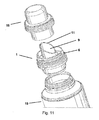
- Fig. 11
- Flasche, Ausgießer und Verschlusskappe in Explosionsdarstellung
-
- 1. Ausgießer
- 2. Nachfüllbehälter
- 3. Adapterelement
- 5. Gewinde
- 6. Gewinde
- 7. Kragen
- 8. Kragen
- 9. Trichter
- 10. Wand
- 11. Trichteröffnung
- 12. Kranz
- 13. Wand
- 14. Boden
- 15. Flasche
- 16. Verschlusskappe
- 17. Schulter
- 18. Hals
- 19. Steg
- 20. Führungsnut
- 21. Zylinder
- 22. Kragen
- 23. Spitze
- 24. Gewinde
- 25. Öffnung
- 26. Membran
- 27. Dünnstelle
- 28. Führungsrippen
- 29. Führungsrippen
- 30. Öffnung
-
Fig. 1 zeigt eine Flasche 15 mit Ausgießer 1 als Vorratsgebinde und einen Nachfüllbehälter 2 mit dem Adapterelement 3 im ungekuppelten Zustand von Nachfüllbehälter 2 und Flasche 15. Das Adapterelement 3 ist dabei in derart ausgestaltet, dass es in der Über-Kopf-Stellung des Nachfüllbehälters 2 - wie inFig. 2 angedeutet - mit dem Ausgießer 1 der Flasche 15 gekuppelt werden kann, so dass das in dem Nachfüllbehälter 2 bevorratete Füllgut schwerkraftbewirkt aus dem Nachfüllbehälter 2 durch den Ausgießer 1 in die Flasche 15 einfließen kann. - In
Fig. 3 und Fig. 4 wird nachfolgend das Adapterelement 3 näher erläutert.
Zunächst wird aufFig. 3 eingegangen, die das Adapterelement 3 mit perspektivischer Ansicht auf die nachfüllbehälterseitige Membranfläche 26 zeigt. - Das bevorzugt aus einem Kunststoffmaterial, insbesondere durch ein Spritzgussverfahren, hergestellte Adapterelement 3 weist einen umlaufenden, zylinderförmigen Kragen 22 auf, auf dessen Innenseite ein Innengewinde 24 als Befestigungsmittel zur flüssigkeitsdichten Befestigung an einem Nachfüllbehälter 2 versehen ist.
- Der Adapter 3 umfasst des Weiteren ein Zylinderelement 21, das sich vom umlaufenden Kragen 22 ausgehend in die vom Inneren des Nachfüllbehälters abgewandte Richtung erstreckt. Das Zylinderelement 21 und der Kragen 22 sind konzentrisch zueinander angeordnet, wobei der Kragen 22 einen größeren Durchmesser aufweist als der Zylinder 21.
- Zwischen Kragen 22 und Zylinderelement 21 ist die Membran 26 angeordnet, die den Kragen 22 vollständig vom Zylinderelement 21 trennt. Die Membran 26 kann einstückig mit dem Adapter 3 ausgebildet sein oder als separates Element in den Adapter 3 eingepasst sein, wobei die Membran 26 dann bevorzugt stoffschlüssig im Adapter 3 fixiert ist.
- Das Zylinderelement 21 weist ferner eine Führungsnut 20 auf, die in derart konfiguriert ist, dass das Zylinderelement 21 - wie beispielsweise aus
Fig. 7 ersichtlich - über den Trichter 9 und einen aus der Trichterebene herausstehenden Steg 19 des Ausgießers 1 lösbar gestülpt werden kann. Hierdurch wird die Positionierung des Adapterelements 3 relativ zum Ausgießer 1 in einer Art Schlüssel-Schloss-Prinzip festgelegt. - Im Weiteren wird auf
Fig. 4 eingegangen, die das Adapterelement 3 mit perspektivischer Ansicht auf die ausgießerseitige Membranfläche 26 zeigt. - Man erkennt zunächst die U-förmige Ausgestaltung der Führungsnut 20 am Zylinderelement 21. Die Membran 26 weist auf der ausgießerseitigen Membranfläche linienförmige Dünnstellen 27 auf, die zumindest abschnittsweise der Projektion der Trichterausformung 9 des Ausgießers 1 entsprechen, so dass beim Kuppeln von Adapterelement 3 mit dem Ausgießer 1 der Trichter 9 zumindest abschnittsweise auf die Dünnstelle 27 stößt.
- Die in
Fig. 4 gezeigte Dünnstelle 27 weist einen T-förmigen, zum Rand des Zylinders 21 gerichteten und einen Y-förmigen Abschnitt, in etwa der Mitte der Membran 26 auf. Der T-förmigen Abschnitt ist in derart konfiguriert und positioniert, dass er beim Kuppeln von Adapterelement 3 mit dem Ausgießer 1 auf die Spitze 23 des Trichters 9 stößt, was beispielsweise ausFig. 9 ersichtlich ist. - Diese Konfiguration von T- und Y-förmigen Abschnitt führt beim Durchstoßen der Membran 26 mit dem Ausgießer 1 dazu, dass sich die Membran 26 entlang der T- und Y-förmigen Abschnitte in zwei Flügel teilt, wodurch ein unbeabsichtigtes Verstopfen der Ausgießöffnung der Adapteröffnung verhindert und ein definiertes Einreißen und Öffnen der Ausgießöffnung gewährleistet ist.
- Auf der Innenseite des Zylinderelements 21 sind im Bereich der T-förmigen Dünnstelle 27 von der Ausgießöffnung des Zylinderelements 21 zur Membran 26 hin rampenförmig verlaufende Führungsrippen 29 angeordnet, die beim Kuppelvorgang - wie aus
Fig. 8 ersichtlich - die Spitze 23 des Trichters 9 kontrolliert an die zur Durchstoßung vorgesehene Stelle der Membran 26 führen. - Die Führungsnut 20 endet in einem Abstand zum ausgießseitigen Rand des Zylinderelements 21 wobei sich eine im Wesentlichen V-förmige Öffnung 30 von der Führungsnut 20 ausgehend zum ausgießseitigen Rand des Zylinderelements 21 erstreckt. Hierdurch wird das Überstülpen des Adapterelements 3 über den Trichter 9 vereinfacht, da der Steg 19 durch die V-förmige Öffnung 30 beim Kupplungsvorgang automatisch in die Führungsnut 20 geführt wird.
- Zusätzlich sind auf der zum Ausgießer hin gerichteten Oberfläche der Membran 26 weitere rampenartige Führungsrippen 28 angeordnet. Diese Führungsrippen 28 bewirken beim Aufsetzen des Ausgießers 1 auf die Membran 26, dass der Ausgießer 1 genau auf die Dünnstelle 27 geführt wird. Hierzu sind die Führungsrippen 28 zum Zylinder 21 hin abfallend, rampenartig ausgebildet, so dass der Ausgießer beim Aufsetzen automatisch in die richtige Position über der Dünnstelle 27 geführt wird, selbst wenn der Ausgießer 1 vom Benutzer beim Kupplungsvorgang nicht exakt aufgesetzt wurde oder sich der Trichter 9 des Ausgießers 1 beim Kuppelvorgang unter der Druckbelastung verformt.
-
Fig. 5 zeigt eine Detailansicht des Ausgießers in perspektivischer Aufsicht aus der gut zu erkennen ist, dass an der von dem Inneren der Flasche 15 weit entferntesten Stelle des Trichters 9 eine Spitze 23 angeordnet ist, die über den Rand der Trichters 9 hinausragt. Wie der Detailansicht derFig. 5 ebenfalls ersichtlich ist, ist die Spitze 23 als Rippe an der Trichterinnenwand ausgeformt. Die Spitze 23 liegt dem Steg 19 in einer Flucht direkt gegenüber. - Natürlich ist die Erfindung nicht auf das dargestellte Ausführungsbeispiel beschränkt. Weitere Ausgestaltungen sind möglich, ohne den in den Ansprüchen definierten Bereich zu verlassen.
Claims (8)
- System zum Nachfüllen von fließ- oder schüttfähigen Wasch- oder Reinigungsmitteln umfassend■ Einen auf die Öffnung einer Flasche (15) aufsetzbaren Ausgießer (1) umfassend○ Einen ersten Kragen (8) mit einem Befestigungsmittel (5) zur flüssigkeitsdichten Befestigung des Ausgießers (1) auf einer Flasche (15),○ Einen zweiten Kragen (7) mit einem Befestigungsmittel (6) zur flüssigkeits- und/oder gasdichten Befestigung einer Verschluss- und/oder Dosierkappe (16) an dem Ausgießer (1),○ Eine Wand (10), die sich vom ersten Kragen (8) oder zweiten Kragen (7) in Richtung des Flascheninneren erstreckt,○ Einen Trichter (9), der sich von einer Schulter (17) der Wand (10) aus über den zweiten Kragen (7) hinaus aus der dem Flascheninneren abgewandten Seite des Ausgießers (1) erstreckt, wobei der Trichter (9) eine Trichteröffnung (11) aufweist, sowie■ Ein mit der Ausgießöffnung eines Nachfüllbehälters (2) kuppelbares Adapterelement (3) umfassend○ ein Zylinderelement (21), und dadurch gekennzeichnet, dass das Adapterelement (3)○ einen mit dem Zylinderelement (21) verbundenen umlaufenden Kragen (22) umfasst, an dem ein Befestigungselement (24) zur flüssigkeitsdichten Befestigung des Adapterelements (3) an der Ausgießöffnung des Nachfüllbehälters angeordnet ist, sowie○ eine Membran (26) umfasst, die im auf dem Nachfüllbehälter (2) montierten Zustand des Adapterelements (3) den Nachfüllbehälter (2) verschließt und ein Auslaufen von fließ- oder schüttfähigen Wasch- oder Reinigungsmitteln aus dem Nachfüllbehälter (2), insbesondere auch in einer Über-Kopf-Position des Nachfüllbehälters (2), verhindert, und dass■ das Zylinderelement (21) des Adapterelements (3) eine Führungsnut (20) aufweist, die in derart konfiguriert ist, dass das Zylinderelement (21) über den Trichter (9) und einen aus der Trichterebene herausstehenden Steg (19) des Ausgießers (1) lösbar gestülpt werden kann wobei hierdurch die Positionierung des Adapterelements (3) relativ zum Ausgießer (1) festgelegt ist.
- System zum Nachfüllen von fließ- oder schüttfähigen Wasch- oder Reinigungsmitteln nach Anspruch 1, dadurch gekennzeichnet, dass die Membran (26) eine oder mehrere Dünnstellen (27) aufweist, die zumindest abschnittsweise der Projektion der Trichterausformung entsprechen.
- System zum Nachfüllen von fließ- oder schüttfähigen Wasch- oder Reinigungsmitteln nach Anspruch 2, dadurch gekennzeichnet, dass die Projektion der Trichterausformung eine runde oder ovale Kontur ist und zumindest eine Dünnstelle (27) linienförmig ausgebildet ist und dieser Kontur zumindest abschnittsweise in derart folgt, dass beim Kuppeln von Adapterelement (3) mit dem Ausgießer (1) der Trichter (9) auf die Dünnstelle (27) stößt.
- System zum Nachfüllen von fließ- oder schüttfähigen Wasch- oder Reinigungsmitteln nach einem der vorherigen Ansprüche, dadurch gekennzeichnet, dass an der von dem Inneren der Flasche (15) weit entferntesten Stelle der Trichteröffnung (11) eine Spitze (23) angeordnet ist, die über den Rand der Trichteröffnung (11) hinausragt.
- System zum Nachfüllen von fließ- oder schüttfähigen Wasch- oder Reinigungsmitteln nach einem der vorherigen Ansprüche, dadurch gekennzeichnet, dass die Trichteröffnung (11) als schräg abgeschnittenes Rohr ausgebildet ist.
- System zum Nachfüllen von fließ- oder schüttfähigen Wasch- oder Reinigungsmitteln nach einem der Ansprüche 2 oder 3, dadurch gekennzeichnet, dass die Dünnstelle (27) einen im Wesentlichen T-förmigen Abschnitt aufweist, der in derart konfiguriert ist, dass er beim Kuppeln von Adapterelement (3) mit dem Ausgießer (1) auf die Spitze (23) des Trichters (9) stößt.
- System zum Nachfüllen von fließ- oder schüttfähigen Wasch- oder Reinigungsmitteln nach einem der vorherigen Ansprüche, dadurch gekennzeichnet, dass auf der Innenseite des Zylinderelements (21) von der Ausgießöffnung des Zylinderelements (21) zur Membran (26) hin wenigstens eine rampenförmig verlaufende Führungsrippe (29) angeordnet ist.
- System zum Nachfüllen von fließ- oder schüttfähigen Wasch- oder Reinigungsmitteln nach einem der vorherigen Ansprüche, dadurch gekennzeichnet, dass die Führungsnut (20) in einem Abstand zum ausgießseitigen Rand des Zylinderelements (21) endet und sich eine im Wesentlichen V-förmige Öffnung von der Führungsnut (20) ausgehend zum ausgießseitigen Rand des Zylinderelements (21) erstreckt.
Priority Applications (1)
| Application Number | Priority Date | Filing Date | Title |
|---|---|---|---|
| PL08805082T PL2247507T3 (pl) | 2008-03-06 | 2008-10-06 | Układ do dopełniania płynnych lub sypkich środków piorących lub środków czyszczących |
Applications Claiming Priority (2)
| Application Number | Priority Date | Filing Date | Title |
|---|---|---|---|
| DE102008012973A DE102008012973B3 (de) | 2008-03-06 | 2008-03-06 | System zum Nachfüllen von fließ- oder schüttfähigen Wasch- oder Reinigungsmitteln |
| PCT/EP2008/063338 WO2009109239A1 (de) | 2008-03-06 | 2008-10-06 | SYSTEM ZUM NACHFÜLLEN VON FLIEß- ODER SCHÜTTFÄHIGEN WASCH- ODER REINIGUNGSMITTELN |
Publications (2)
| Publication Number | Publication Date |
|---|---|
| EP2247507A1 EP2247507A1 (de) | 2010-11-10 |
| EP2247507B1 true EP2247507B1 (de) | 2013-12-11 |
Family
ID=40158602
Family Applications (1)
| Application Number | Title | Priority Date | Filing Date |
|---|---|---|---|
| EP08805082.8A Active EP2247507B1 (de) | 2008-03-06 | 2008-10-06 | SYSTEM ZUM NACHFÜLLEN VON FLIEß- ODER SCHÜTTFÄHIGEN WASCH- ODER REINIGUNGSMITTELN |
Country Status (6)
| Country | Link |
|---|---|
| US (1) | US8118066B2 (de) |
| EP (1) | EP2247507B1 (de) |
| DE (1) | DE102008012973B3 (de) |
| ES (1) | ES2444708T3 (de) |
| PL (1) | PL2247507T3 (de) |
| WO (1) | WO2009109239A1 (de) |
Families Citing this family (23)
| Publication number | Priority date | Publication date | Assignee | Title |
|---|---|---|---|---|
| JP5365361B2 (ja) * | 2009-03-26 | 2013-12-11 | 凸版印刷株式会社 | 詰替え容器用口栓 |
| JP5207312B2 (ja) * | 2009-04-30 | 2013-06-12 | 株式会社吉野工業所 | 詰め替え容器 |
| US8585905B2 (en) * | 2010-02-26 | 2013-11-19 | Waters Technologies Corporation | Devices, kits and methods for performing chemical processing |
| CN103282287B (zh) * | 2010-12-27 | 2015-06-03 | 花王株式会社 | 包装体、换装方法以及包装体套件 |
| JP2013227045A (ja) * | 2012-04-26 | 2013-11-07 | Toppan Printing Co Ltd | 繰り返し使用容器及びこれに使用するノズルキャップ |
| JP5948133B2 (ja) * | 2012-04-27 | 2016-07-06 | 株式会社吉野工業所 | 詰め替え容器 |
| JP5933323B2 (ja) * | 2012-04-27 | 2016-06-08 | 株式会社吉野工業所 | 詰め替え容器 |
| FR2995290B1 (fr) * | 2012-09-13 | 2014-09-26 | Rexam Dispensing Sys | Flacon remplissable de distribution d’un produit fluide |
| FR2996828B1 (fr) * | 2012-10-15 | 2014-10-24 | Rexam Dispensing Sys | Flacon remplissable de distribution d’un produit fluide |
| FR2996829B1 (fr) * | 2012-10-15 | 2014-10-24 | Rexam Dispensing Sys | Flacon remplissable de distribution d’un produit fluide |
| JP6183846B2 (ja) * | 2012-11-30 | 2017-08-23 | 花王株式会社 | 詰替え容器用栓体 |
| JP6183847B2 (ja) * | 2012-11-30 | 2017-08-23 | 花王株式会社 | 詰替え容器用栓体 |
| US10046490B2 (en) * | 2014-04-17 | 2018-08-14 | Plastek Industries, Inc. | Snap-over spout fitment and manufacture methods |
| US20170008677A1 (en) * | 2015-07-11 | 2017-01-12 | Plastek Industries, Inc. | Snap-Over Spout Fitment and Manufacture Methods |
| US10994875B2 (en) * | 2016-10-19 | 2021-05-04 | DAO Health | Device and method for transferring breast milk from an irregular shaped reservoir assembly for storage or feeding |
| JP6960731B2 (ja) * | 2016-12-08 | 2021-11-05 | 藤森工業株式会社 | 容器の注出用スパウト |
| US10059492B2 (en) * | 2016-12-15 | 2018-08-28 | Berlin Packaging, Llc | Dispensing container package |
| JP7031146B2 (ja) * | 2017-06-29 | 2022-03-08 | 凸版印刷株式会社 | 軟包装袋と詰替え先容器との嵌合構造及びこれらのセット |
| JP7193305B2 (ja) * | 2018-10-30 | 2022-12-20 | 藤森工業株式会社 | 注出スパウト |
| US10661968B1 (en) | 2019-06-20 | 2020-05-26 | Elc Management Llc | Container system for mixing and dispensing |
| JP7607491B2 (ja) * | 2021-03-30 | 2024-12-27 | 共同印刷株式会社 | 連結具、及び連結具付き詰め替え容器 |
| DE202023102718U1 (de) | 2023-05-18 | 2023-06-05 | Seven Days Cosmetic Gmbh | Behältersystem für flüssige Verbrauchsmaterialien |
| DE102023128698A1 (de) * | 2023-10-19 | 2025-04-24 | Miele & Cie. Kg | Die Erfindung betrifft einen Nachfülladapter zur tropffreien Verbindung eines Nachfüllbeutels mit einem aus einer Wäschebehandlungsmaschine entnehmbaren Waschmittelbehälter |
Family Cites Families (5)
| Publication number | Priority date | Publication date | Assignee | Title |
|---|---|---|---|---|
| US3004566A (en) * | 1958-01-09 | 1961-10-17 | Anthony S Raimo | Pill dispenser |
| US4614437A (en) * | 1984-11-02 | 1986-09-30 | Dougherty Brothers Company | Mixing container and adapter |
| GB8922478D0 (en) * | 1989-10-05 | 1989-11-22 | Procter & Gamble | Flowable product package incorporating a refill facilitating pouring spout |
| US5687865A (en) * | 1991-10-08 | 1997-11-18 | Portola Packaging, Inc. | Spill-reduction cap for fluid container |
| US5746260A (en) * | 1994-01-26 | 1998-05-05 | Colgate-Palmolive Company | Container set comprising at least two containers |
-
2008
- 2008-03-06 DE DE102008012973A patent/DE102008012973B3/de not_active Expired - Fee Related
- 2008-10-06 PL PL08805082T patent/PL2247507T3/pl unknown
- 2008-10-06 EP EP08805082.8A patent/EP2247507B1/de active Active
- 2008-10-06 WO PCT/EP2008/063338 patent/WO2009109239A1/de not_active Ceased
- 2008-10-06 ES ES08805082.8T patent/ES2444708T3/es active Active
-
2010
- 2010-09-07 US US12/876,522 patent/US8118066B2/en not_active Expired - Fee Related
Also Published As
| Publication number | Publication date |
|---|---|
| ES2444708T3 (es) | 2014-02-26 |
| EP2247507A1 (de) | 2010-11-10 |
| US20110011494A1 (en) | 2011-01-20 |
| PL2247507T3 (pl) | 2014-04-30 |
| WO2009109239A1 (de) | 2009-09-11 |
| DE102008012973B3 (de) | 2009-04-02 |
| US8118066B2 (en) | 2012-02-21 |
Similar Documents
| Publication | Publication Date | Title |
|---|---|---|
| EP2247507B1 (de) | SYSTEM ZUM NACHFÜLLEN VON FLIEß- ODER SCHÜTTFÄHIGEN WASCH- ODER REINIGUNGSMITTELN | |
| DE3006773C2 (de) | Garantie-Verschlußkappe | |
| DE3043899C2 (de) | ||
| EP0636104B1 (de) | Anordnung zum nachfüllen eines behälters | |
| EP2046657A2 (de) | Verschlusskappe für einen mit einer medizinischen flüssigkeit befüllten behälter und behälter mit einer verschlusskappe | |
| EP3228559A1 (de) | Dosierkapsel für zusatzstoffe für mix-getränke | |
| DE69404505T2 (de) | Auslass-Verschluss | |
| EP2601112A1 (de) | Schraubverschluss mit flexband | |
| WO2005087604A1 (de) | Sicherheitsdrehverschluss für eine mehrkammerflasche, insbesondere für eine zweikammerflasche | |
| EP2328816B1 (de) | Tubenförmiger dosierbehälter | |
| EP0082439B1 (de) | Dosierverschluss für Behälter für flüssige oder rieselfähige Produkte | |
| EP0447997A2 (de) | Dosenartige Verpackung für fliessfähige Produkte und Verfahren zu ihrer Herstellung | |
| EP2134618B1 (de) | Verschlussvorrichtung für einen trinkbehälter | |
| EP3552983B1 (de) | Gebinde mit einem sicherungsring zur transportsicherung eines deckels | |
| DE69618143T2 (de) | Kartonverpackungssystem | |
| DE826556C (de) | Verschluss fuer Falschen oder aehnliche Behaelter | |
| EP3544902B1 (de) | Flasche mit ausgiesser und dosierbecher | |
| EP0173194B1 (de) | Transport- und Lagerbehälter | |
| EP0647197B1 (de) | Verschluss für einen behälter für schütt- oder fliessfähiges gut | |
| DE19711578C2 (de) | Vorrichtung zum Öffnen und Wiederverschließen von Behältern | |
| DE19928534A1 (de) | Einfaltbarer Behälterverschluss mit anscharnierter Kappe | |
| DD292187A5 (de) | Verpackungsbehaelter zur aufnahme eines fliessfaehigen produktes | |
| EP3543171B1 (de) | Deckeladapter, deckel, gebinde und verfahren zum entleeren mindestens eines folienbeutels | |
| DE29801270U1 (de) | Ausgiesseinschweissteil | |
| DE202024105790U1 (de) | Sicherheits-Verschlussvorrichtung |
Legal Events
| Date | Code | Title | Description |
|---|---|---|---|
| PUAI | Public reference made under article 153(3) epc to a published international application that has entered the european phase |
Free format text: ORIGINAL CODE: 0009012 |
|
| 17P | Request for examination filed |
Effective date: 20100506 |
|
| AK | Designated contracting states |
Kind code of ref document: A1 Designated state(s): AT BE BG CH CY CZ DE DK EE ES FI FR GB GR HR HU IE IS IT LI LT LU LV MC MT NL NO PL PT RO SE SI SK TR |
|
| AX | Request for extension of the european patent |
Extension state: AL BA MK RS |
|
| RIN1 | Information on inventor provided before grant (corrected) |
Inventor name: BARTHEL, WOLFGANG Inventor name: RAHAL, KAMEL Inventor name: MUEHLHAUSEN, HANS-GEORG |
|
| DAX | Request for extension of the european patent (deleted) | ||
| REG | Reference to a national code |
Ref country code: DE Ref legal event code: R079 Ref document number: 502008011065 Country of ref document: DE Free format text: PREVIOUS MAIN CLASS: B65C0009000000 Ipc: B67C0009000000 |
|
| GRAP | Despatch of communication of intention to grant a patent |
Free format text: ORIGINAL CODE: EPIDOSNIGR1 |
|
| RIC1 | Information provided on ipc code assigned before grant |
Ipc: B65D 47/06 20060101ALI20130704BHEP Ipc: B65D 47/10 20060101ALI20130704BHEP Ipc: B67B 7/86 20060101ALI20130704BHEP Ipc: B67C 9/00 20060101AFI20130704BHEP |
|
| INTG | Intention to grant announced |
Effective date: 20130717 |
|
| GRAS | Grant fee paid |
Free format text: ORIGINAL CODE: EPIDOSNIGR3 |
|
| GRAA | (expected) grant |
Free format text: ORIGINAL CODE: 0009210 |
|
| AK | Designated contracting states |
Kind code of ref document: B1 Designated state(s): AT BE BG CH CY CZ DE DK EE ES FI FR GB GR HR HU IE IS IT LI LT LU LV MC MT NL NO PL PT RO SE SI SK TR |
|
| REG | Reference to a national code |
Ref country code: GB Ref legal event code: FG4D Free format text: NOT ENGLISH |
|
| REG | Reference to a national code |
Ref country code: CH Ref legal event code: EP |
|
| REG | Reference to a national code |
Ref country code: AT Ref legal event code: REF Ref document number: 644469 Country of ref document: AT Kind code of ref document: T Effective date: 20140115 |
|
| REG | Reference to a national code |
Ref country code: IE Ref legal event code: FG4D Free format text: LANGUAGE OF EP DOCUMENT: GERMAN |
|
| REG | Reference to a national code |
Ref country code: DE Ref legal event code: R096 Ref document number: 502008011065 Country of ref document: DE Effective date: 20140206 |
|
| REG | Reference to a national code |
Ref country code: ES Ref legal event code: FG2A Ref document number: 2444708 Country of ref document: ES Kind code of ref document: T3 Effective date: 20140226 |
|
| REG | Reference to a national code |
Ref country code: NL Ref legal event code: VDEP Effective date: 20131211 |
|
| PG25 | Lapsed in a contracting state [announced via postgrant information from national office to epo] |
Ref country code: NO Free format text: LAPSE BECAUSE OF FAILURE TO SUBMIT A TRANSLATION OF THE DESCRIPTION OR TO PAY THE FEE WITHIN THE PRESCRIBED TIME-LIMIT Effective date: 20140311 Ref country code: LT Free format text: LAPSE BECAUSE OF FAILURE TO SUBMIT A TRANSLATION OF THE DESCRIPTION OR TO PAY THE FEE WITHIN THE PRESCRIBED TIME-LIMIT Effective date: 20131211 Ref country code: NL Free format text: LAPSE BECAUSE OF FAILURE TO SUBMIT A TRANSLATION OF THE DESCRIPTION OR TO PAY THE FEE WITHIN THE PRESCRIBED TIME-LIMIT Effective date: 20131211 Ref country code: FI Free format text: LAPSE BECAUSE OF FAILURE TO SUBMIT A TRANSLATION OF THE DESCRIPTION OR TO PAY THE FEE WITHIN THE PRESCRIBED TIME-LIMIT Effective date: 20131211 Ref country code: SE Free format text: LAPSE BECAUSE OF FAILURE TO SUBMIT A TRANSLATION OF THE DESCRIPTION OR TO PAY THE FEE WITHIN THE PRESCRIBED TIME-LIMIT Effective date: 20131211 Ref country code: HR Free format text: LAPSE BECAUSE OF FAILURE TO SUBMIT A TRANSLATION OF THE DESCRIPTION OR TO PAY THE FEE WITHIN THE PRESCRIBED TIME-LIMIT Effective date: 20131211 |
|
| REG | Reference to a national code |
Ref country code: PL Ref legal event code: T3 |
|
| REG | Reference to a national code |
Ref country code: LT Ref legal event code: MG4D |
|
| PG25 | Lapsed in a contracting state [announced via postgrant information from national office to epo] |
Ref country code: CY Free format text: LAPSE BECAUSE OF FAILURE TO SUBMIT A TRANSLATION OF THE DESCRIPTION OR TO PAY THE FEE WITHIN THE PRESCRIBED TIME-LIMIT Effective date: 20131211 Ref country code: LV Free format text: LAPSE BECAUSE OF FAILURE TO SUBMIT A TRANSLATION OF THE DESCRIPTION OR TO PAY THE FEE WITHIN THE PRESCRIBED TIME-LIMIT Effective date: 20131211 |
|
| PG25 | Lapsed in a contracting state [announced via postgrant information from national office to epo] |
Ref country code: IS Free format text: LAPSE BECAUSE OF FAILURE TO SUBMIT A TRANSLATION OF THE DESCRIPTION OR TO PAY THE FEE WITHIN THE PRESCRIBED TIME-LIMIT Effective date: 20140411 Ref country code: EE Free format text: LAPSE BECAUSE OF FAILURE TO SUBMIT A TRANSLATION OF THE DESCRIPTION OR TO PAY THE FEE WITHIN THE PRESCRIBED TIME-LIMIT Effective date: 20131211 |
|
| PG25 | Lapsed in a contracting state [announced via postgrant information from national office to epo] |
Ref country code: PT Free format text: LAPSE BECAUSE OF FAILURE TO SUBMIT A TRANSLATION OF THE DESCRIPTION OR TO PAY THE FEE WITHIN THE PRESCRIBED TIME-LIMIT Effective date: 20140411 Ref country code: SK Free format text: LAPSE BECAUSE OF FAILURE TO SUBMIT A TRANSLATION OF THE DESCRIPTION OR TO PAY THE FEE WITHIN THE PRESCRIBED TIME-LIMIT Effective date: 20131211 Ref country code: RO Free format text: LAPSE BECAUSE OF FAILURE TO SUBMIT A TRANSLATION OF THE DESCRIPTION OR TO PAY THE FEE WITHIN THE PRESCRIBED TIME-LIMIT Effective date: 20131211 |
|
| REG | Reference to a national code |
Ref country code: DE Ref legal event code: R097 Ref document number: 502008011065 Country of ref document: DE |
|
| PLBE | No opposition filed within time limit |
Free format text: ORIGINAL CODE: 0009261 |
|
| STAA | Information on the status of an ep patent application or granted ep patent |
Free format text: STATUS: NO OPPOSITION FILED WITHIN TIME LIMIT |
|
| PG25 | Lapsed in a contracting state [announced via postgrant information from national office to epo] |
Ref country code: DK Free format text: LAPSE BECAUSE OF FAILURE TO SUBMIT A TRANSLATION OF THE DESCRIPTION OR TO PAY THE FEE WITHIN THE PRESCRIBED TIME-LIMIT Effective date: 20131211 |
|
| 26N | No opposition filed |
Effective date: 20140912 |
|
| REG | Reference to a national code |
Ref country code: DE Ref legal event code: R097 Ref document number: 502008011065 Country of ref document: DE Effective date: 20140912 |
|
| PG25 | Lapsed in a contracting state [announced via postgrant information from national office to epo] |
Ref country code: SI Free format text: LAPSE BECAUSE OF FAILURE TO SUBMIT A TRANSLATION OF THE DESCRIPTION OR TO PAY THE FEE WITHIN THE PRESCRIBED TIME-LIMIT Effective date: 20131211 |
|
| PG25 | Lapsed in a contracting state [announced via postgrant information from national office to epo] |
Ref country code: LU Free format text: LAPSE BECAUSE OF FAILURE TO SUBMIT A TRANSLATION OF THE DESCRIPTION OR TO PAY THE FEE WITHIN THE PRESCRIBED TIME-LIMIT Effective date: 20141006 Ref country code: MC Free format text: LAPSE BECAUSE OF FAILURE TO SUBMIT A TRANSLATION OF THE DESCRIPTION OR TO PAY THE FEE WITHIN THE PRESCRIBED TIME-LIMIT Effective date: 20131211 |
|
| REG | Reference to a national code |
Ref country code: CH Ref legal event code: PL |
|
| GBPC | Gb: european patent ceased through non-payment of renewal fee |
Effective date: 20141006 |
|
| PG25 | Lapsed in a contracting state [announced via postgrant information from national office to epo] |
Ref country code: BE Free format text: LAPSE BECAUSE OF NON-PAYMENT OF DUE FEES Effective date: 20141031 |
|
| REG | Reference to a national code |
Ref country code: IE Ref legal event code: MM4A |
|
| PG25 | Lapsed in a contracting state [announced via postgrant information from national office to epo] |
Ref country code: CH Free format text: LAPSE BECAUSE OF NON-PAYMENT OF DUE FEES Effective date: 20141031 Ref country code: LI Free format text: LAPSE BECAUSE OF NON-PAYMENT OF DUE FEES Effective date: 20141031 Ref country code: GB Free format text: LAPSE BECAUSE OF NON-PAYMENT OF DUE FEES Effective date: 20141006 |
|
| REG | Reference to a national code |
Ref country code: FR Ref legal event code: PLFP Year of fee payment: 8 |
|
| PG25 | Lapsed in a contracting state [announced via postgrant information from national office to epo] |
Ref country code: IE Free format text: LAPSE BECAUSE OF NON-PAYMENT OF DUE FEES Effective date: 20141006 |
|
| REG | Reference to a national code |
Ref country code: AT Ref legal event code: MM01 Ref document number: 644469 Country of ref document: AT Kind code of ref document: T Effective date: 20141006 |
|
| PG25 | Lapsed in a contracting state [announced via postgrant information from national office to epo] |
Ref country code: AT Free format text: LAPSE BECAUSE OF NON-PAYMENT OF DUE FEES Effective date: 20141006 |
|
| PG25 | Lapsed in a contracting state [announced via postgrant information from national office to epo] |
Ref country code: BG Free format text: LAPSE BECAUSE OF FAILURE TO SUBMIT A TRANSLATION OF THE DESCRIPTION OR TO PAY THE FEE WITHIN THE PRESCRIBED TIME-LIMIT Effective date: 20131211 |
|
| PG25 | Lapsed in a contracting state [announced via postgrant information from national office to epo] |
Ref country code: GR Free format text: LAPSE BECAUSE OF FAILURE TO SUBMIT A TRANSLATION OF THE DESCRIPTION OR TO PAY THE FEE WITHIN THE PRESCRIBED TIME-LIMIT Effective date: 20140312 |
|
| PG25 | Lapsed in a contracting state [announced via postgrant information from national office to epo] |
Ref country code: TR Free format text: LAPSE BECAUSE OF FAILURE TO SUBMIT A TRANSLATION OF THE DESCRIPTION OR TO PAY THE FEE WITHIN THE PRESCRIBED TIME-LIMIT Effective date: 20131211 Ref country code: HU Free format text: LAPSE BECAUSE OF FAILURE TO SUBMIT A TRANSLATION OF THE DESCRIPTION OR TO PAY THE FEE WITHIN THE PRESCRIBED TIME-LIMIT; INVALID AB INITIO Effective date: 20081006 Ref country code: MT Free format text: LAPSE BECAUSE OF FAILURE TO SUBMIT A TRANSLATION OF THE DESCRIPTION OR TO PAY THE FEE WITHIN THE PRESCRIBED TIME-LIMIT Effective date: 20131211 |
|
| REG | Reference to a national code |
Ref country code: FR Ref legal event code: PLFP Year of fee payment: 9 |
|
| REG | Reference to a national code |
Ref country code: FR Ref legal event code: PLFP Year of fee payment: 10 |
|
| REG | Reference to a national code |
Ref country code: FR Ref legal event code: PLFP Year of fee payment: 11 |
|
| PGFP | Annual fee paid to national office [announced via postgrant information from national office to epo] |
Ref country code: PL Payment date: 20180924 Year of fee payment: 11 |
|
| PGFP | Annual fee paid to national office [announced via postgrant information from national office to epo] |
Ref country code: CZ Payment date: 20181004 Year of fee payment: 11 |
|
| PGFP | Annual fee paid to national office [announced via postgrant information from national office to epo] |
Ref country code: IT Payment date: 20181024 Year of fee payment: 11 |
|
| PG25 | Lapsed in a contracting state [announced via postgrant information from national office to epo] |
Ref country code: CZ Free format text: LAPSE BECAUSE OF NON-PAYMENT OF DUE FEES Effective date: 20191006 |
|
| PG25 | Lapsed in a contracting state [announced via postgrant information from national office to epo] |
Ref country code: IT Free format text: LAPSE BECAUSE OF NON-PAYMENT OF DUE FEES Effective date: 20191006 |
|
| REG | Reference to a national code |
Ref country code: ES Ref legal event code: FD2A Effective date: 20210301 |
|
| PG25 | Lapsed in a contracting state [announced via postgrant information from national office to epo] |
Ref country code: ES Free format text: LAPSE BECAUSE OF NON-PAYMENT OF DUE FEES Effective date: 20191007 |
|
| PG25 | Lapsed in a contracting state [announced via postgrant information from national office to epo] |
Ref country code: PL Free format text: LAPSE BECAUSE OF NON-PAYMENT OF DUE FEES Effective date: 20191006 |
|
| P01 | Opt-out of the competence of the unified patent court (upc) registered |
Effective date: 20230530 |
|
| PGFP | Annual fee paid to national office [announced via postgrant information from national office to epo] |
Ref country code: DE Payment date: 20251021 Year of fee payment: 18 |
|
| PGFP | Annual fee paid to national office [announced via postgrant information from national office to epo] |
Ref country code: FR Payment date: 20251029 Year of fee payment: 18 |
|
| REG | Reference to a national code |
Ref country code: DE Ref legal event code: R084 Ref document number: 502008011065 Country of ref document: DE |