EP2247521B1 - Spulenhalter - Google Patents
Spulenhalter Download PDFInfo
- Publication number
- EP2247521B1 EP2247521B1 EP09716443.8A EP09716443A EP2247521B1 EP 2247521 B1 EP2247521 B1 EP 2247521B1 EP 09716443 A EP09716443 A EP 09716443A EP 2247521 B1 EP2247521 B1 EP 2247521B1
- Authority
- EP
- European Patent Office
- Prior art keywords
- drive shaft
- tension
- clamping
- ring
- circumference
- Prior art date
- Legal status (The legal status is an assumption and is not a legal conclusion. Google has not performed a legal analysis and makes no representation as to the accuracy of the status listed.)
- Not-in-force
Links
- 239000012530 fluid Substances 0.000 claims description 16
- 230000006835 compression Effects 0.000 claims description 6
- 238000007906 compression Methods 0.000 claims description 6
- 238000004804 winding Methods 0.000 description 26
- 239000000463 material Substances 0.000 description 8
- 238000011161 development Methods 0.000 description 2
- 230000018109 developmental process Effects 0.000 description 2
- 238000000034 method Methods 0.000 description 2
- 239000011343 solid material Substances 0.000 description 2
- 229920000297 Rayon Polymers 0.000 description 1
- 230000035508 accumulation Effects 0.000 description 1
- 238000009825 accumulation Methods 0.000 description 1
- 230000000694 effects Effects 0.000 description 1
- 229920001971 elastomer Polymers 0.000 description 1
- 239000000806 elastomer Substances 0.000 description 1
- 238000007373 indentation Methods 0.000 description 1
- 230000002093 peripheral effect Effects 0.000 description 1
- 239000002964 rayon Substances 0.000 description 1
- 238000005096 rolling process Methods 0.000 description 1
- 239000007779 soft material Substances 0.000 description 1
Images

Classifications
-
- B—PERFORMING OPERATIONS; TRANSPORTING
- B65—CONVEYING; PACKING; STORING; HANDLING THIN OR FILAMENTARY MATERIAL
- B65H—HANDLING THIN OR FILAMENTARY MATERIAL, e.g. SHEETS, WEBS, CABLES
- B65H54/00—Winding, coiling, or depositing filamentary material
- B65H54/02—Winding and traversing material on to reels, bobbins, tubes, or like package cores or formers
- B65H54/40—Arrangements for rotating packages
- B65H54/54—Arrangements for supporting cores or formers at winding stations; Securing cores or formers to driving members
- B65H54/543—Securing cores or holders to supporting or driving members, e.g. collapsible mandrels
-
- B—PERFORMING OPERATIONS; TRANSPORTING
- B65—CONVEYING; PACKING; STORING; HANDLING THIN OR FILAMENTARY MATERIAL
- B65H—HANDLING THIN OR FILAMENTARY MATERIAL, e.g. SHEETS, WEBS, CABLES
- B65H75/00—Storing webs, tapes, or filamentary material, e.g. on reels
- B65H75/02—Cores, formers, supports, or holders for coiled, wound, or folded material, e.g. reels, spindles, bobbins, cop tubes, cans, mandrels or chucks
- B65H75/18—Constructional details
- B65H75/24—Constructional details adjustable in configuration, e.g. expansible
- B65H75/242—Expansible spindles, mandrels or chucks, e.g. for securing or releasing cores, holders or packages
- B65H75/245—Expansible spindles, mandrels or chucks, e.g. for securing or releasing cores, holders or packages by deformation of an elastic or flexible material
-
- B—PERFORMING OPERATIONS; TRANSPORTING
- B65—CONVEYING; PACKING; STORING; HANDLING THIN OR FILAMENTARY MATERIAL
- B65H—HANDLING THIN OR FILAMENTARY MATERIAL, e.g. SHEETS, WEBS, CABLES
- B65H2701/00—Handled material; Storage means
- B65H2701/30—Handled filamentary material
- B65H2701/31—Textiles threads or artificial strands of filaments
Definitions
- the invention relates to a bobbin holder for mounting a winding tube and receiving a wound bobbin.
- a generic bobbin holder is from the US 4,458,850 known.
- the wound thread bobbins are usually wound and held on the circumference of a winding tube.
- the bobbins are held and driven by a bobbin holder, wherein the bobbin holders have releasable clamping devices, so that the bobbins can be easily changed at the beginning of the process and at the end of the process.
- bobbin holders have been proven in which the bobbin tubes are pushed onto a free projecting end of the bobbin holder.
- the clamping device for fixing the winding tube are arranged in such a coil holders on the circumference of a drive shaft.
- the trained on the circumference of a drive shaft clamping device is formed by a plurality of clamping sleeves and a plurality of clamping rings, each having a circumferential clamping collar protruding between the clamping sleeves.
- a clamping sleeve held at the end of the drive shaft is connected to a tensioning piston, which is guided in a guide opening of the drive shaft.
- the clamping sleeves are moved by means of the clamping piston on the circumference of the drive shaft against a stop that deform between the clamping sleeves arranged clamping rings and thereby generate a clamping force on the inner circumference of the winding tubes.
- the clamping rings are formed from a deformable very soft material such as an elastomer.
- a coil fastening device which makes use of a multi-slotted clamping ring which is held with clamping means by undercuts. To achieve the clamping effect, a plurality of different interacting clamping means must be used.
- a coil holder according to the preamble of claim 1 which has a (radially movable) clamping ring with a slot, so that a material can be used which shows little fatigue.
- the invention is based on the principle that the generation of the radial forces for fixing the winding tubes takes place solely from the material deformation of the clamping ring.
- the invention essentially uses the geometric shape of the clamping ring to generate radial forces for tensioning the winding tubes.
- the clamping ring is cut at the periphery at one point, so that there are two opposite in a separating slot ring ends of the clamping ring.
- the essential clamping force from the change in the geometric shape of the clamping ring out As a result, relatively firm and hard materials for the clamping ring can be used, which have correspondingly long service life.
- the clamping ring is provided in a region opposite the separating slot at least with a mass balance opening. This allows the masses of the clamping ring held on the circumference of the drive shaft to be distributed uniformly, so that larger imbalance phenomena are avoided.
- the mass balance openings of their size and / or number is such that in the tensioned state of the clamping ring with splayed ring ends a complete mass balance is generated at the periphery of the drive shaft.
- the clamping ring of the separating slot in the clamping ring is preferably formed axially aligned and executed with a slot height of ⁇ 2mm. In principle, however, it is also possible to form the separating slot in an oblique arrangement in the clamping ring.
- the clamping ring In order to obtain an expansion of the ring ends under axial load of the clamping ring, the clamping ring has on both end sides of the clamping collar each having an inclined clamping surface on which cooperates with a pressure surface of the clamping sleeve. This allows relatively high radial forces to initiate spreading of the clamping ring in the clamping collar, which leads to high fixing forces in the interior of the winding tube.
- the clamping surfaces preferably have an angle of inclination in the range between 15 ° and 45 ° with respect to a normal of the clamping collar.
- the axial forces generated by the clamping piston can be kept relatively small for bracing the clamping ring.
- the clamping ring on an inner cylindrical holding web, which is connected at the periphery in a central region with the clamping collar such that the retaining web to the.
- Forming end faces protrusions.
- the holding web is interrupted at the periphery by a plurality of cutouts, which are arranged distributed uniformly over the circumference. This sufficient elasticity of the clamping ring is generated even with very solid materials, which allow the spreading of the clamping ring.
- one of the clamping sleeves is preferably formed with a pot-shaped Stimende and performed directly at the free end of the drive shaft.
- a guided within a guide opening of the drive shaft piston in a simple manner at the front end of the drive shaft with the clamping sleeve connect.
- the clamping piston is preferably held within the guide opening by means of a spring force of a compression spring in a clamping position at which the clamping sleeves spread open the clamping rings.
- the tensioning piston can be guided into a release position by means of a fluid force of an optionally deliverable pressure fluid.
- the drive shaft is connected to the stored end with a rotor of an electric motor.
- the rotor is arranged for this purpose directly on the circumference of the drive shaft, wherein the rotor is associated with an opposite stator of the electric motor.
- the drive shaft can be stored preferably by a plurality of rolling bearings, which are arranged on both sides of the rotor and are held in a motor housing of the electric motor.
- FIG. 1 schematically a first embodiment of the coil holder according to the invention is shown in a cross-sectional view.
- the bobbin holder has a drive shaft 1 which has a bearing end 2 and a cantilevered tensioning end 3.
- a clamping device 4 is held in order to clamp a winding tube 36 on the circumference of the exciting end 3 of the drive shaft 1.
- the clamping device 4 has a plurality on the circumference of the drive shaft 1 hintercrcinander arranged clamping sleeves 5.1, 5.2 and 5.3. Between the clamping sleeves 5.1 and 5.2 and between the clamping sleeves 5.2 and 5.3 each have a clamping ring 6.1 and 6.2 is arranged. In this case, the clamping rings protrude 6.1 and 6.2, each with a clamping collar 17 between the clamping sleeves 5.1, 5.2 and 5.3.
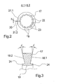
- FIGS. 2 and 3 Reference is made, in which one of the clamping rings 6.1 is shown schematically in several views. The following description applies to both figures, insofar as no explicit reference is made to one of the figures.
- the clamping ring 6.1 has a circumferential clamping collar 17.
- the clamping collar 17 is severed at one point of the circumference by a separating slot 20 throughout.
- the separating slot 20 extends between the opposite ring ends 21.1 and 21.2.
- the distance between the ring ends 21.1 and 21.2 forms the height of the separating slot 20, which in Fig. 2 is indicated by the lowercase letter h.
- the separating slot 20 is very narrow in its height and is preferably designed to be less than 2 mm.
- a plurality of mass balance openings 22 are introduced into the clamping collar 17.
- the number and size of the mass balance openings 22 is designed for a geometric shape of the clamping ring, which is set under load in the spread state of the ring ends 21.1 and 21.2.
- the ring ends 21.1 and 21.2 in the separating slot 20 with a greater distance from each other, so that sets on the periphery of the drive shaft on the side of the separating slots a greater mass loss through the separating slot 20.
- a plurality of mass compensation openings 22 are formed on the opposite side of the separating slot 20, so that the clamping ring 6.1 does not generate any imbalance on the circumference of the drive shaft.
- two opposing clamping surfaces 18.1 and 18.2 are formed on the clamping collar 17 of the clamping ring.
- the clamping surfaces 18.1 and 18.2 have a tilt angle ⁇ relative to a normal.
- the inclination angle ⁇ is identical in both clamping surfaces 18.1 and 18.2 and is preferably in a range of 15 ° to 45 °.
- the clamping surfaces 18.1 and 18.2 act in the operating state - as explained later - with pressure surfaces 25 of the clamping sleeves 5.1, 5.2 and 5.3 together.
- a circumferential cylindrical holding web 19 is formed, which in each case forms a projection 24 for each end face of the clamping ring 6.1.
- the holding web 19 is connected to the clamping collar 17 in the central region.
- the retaining web 19 and the clamping collar 17 is severed at several points of the circumference by cutouts 23.
- the cutouts 23 are uniformly distributed on the circumference of the retaining web 19.
- the holder web 19 is severed into a plurality of sections.
- the size and shape of the cutouts 23 is dimensioned such that, despite the use of a solid material, for example, a hard plastic sufficient elasticity of the clamping ring for spreading the ring ends 21.1 and 21.2 results.
- Fig. 1 is the clamping ring 6.1 and the same to the clamping ring 6.1 formed clamping ring 6.2 shown in an expanded position for fixing the winding tube 36.
- the clamping rings 6.1 and 6.2 are held by the winding tubes 5.1, 5.2 and 5.3.
- the bearing end 2 of the drive shaft 1 facing clamping sleeve 5.1 is preferably fixed to the circumference of the drive shaft 1 and forms a stop with an excellent collar 29.
- the clamping sleeve 5.1 At the clamping ring 6.1 facing front end, the clamping sleeve 5.1 a pressure surface 25 and an indentation 26 to a To allow surface contact and contact with the clamping ring 6.1.
- the adjoining clamping sleeve 5.2 is displaceably guided on the circumference of the drive shaft 1 and has in each case a pressure surface 25 and an incision 26 at both front ends.
- the clamping sleeve 5.2 rests with its left pressure surface 25 on the clamping ring 6.1 and with the right pressure surface 25 on the clamping ring 6.2.
- the guided at the end of the drive shaft 1 clamping sleeve 5.3 also has a relation to the clamping ring 6.2 trained pressure surface 25 and an incision 26.
- a cup-shaped front end 14 is formed, so that the clamping sleeve 5.3 surrounds the free end of the drive shaft 1 cup-shaped.
- the clamping sleeves 5.1, 5.2 and 5.3 a plurality of material recesses 28.
- the clamping sleeves 5.2 and 5.3 relative to the circumference of the drive shaft 1 realize small sliding surfaces.
- unnecessary material accumulations are avoided on the circumference of the drive shaft 1.
- the front end 14 of the clamping sleeve 5.3 is connected via a fastening means 35 with a clamping piston 7.
- the tensioning piston 7 is designed as a stepped piston and is guided in a guide opening 8 at the free end face of the drive shaft 1.
- the clamping piston 7 has a guide section 11, which is guided pressure-tight in the guide opening 8.
- a pressure chamber 37 is formed at the closed end of the guide opening 8, which acts on the end face of the guide portion 11.
- the pressure chamber 37 is connected via a fluid channel 15 with a arranged at the bearing end 2 of the drive shaft 1 fluid port 16.
- the clamping piston 7 has a smaller diameter holding portion 13 which protrudes with its free end from the guide opening 8 and is fixedly connected to the front end 14 of the clamping sleeve 5.3.
- a compression spring 10 is held within the guide opening 8, which is supported on the one hand a diameter stage between the guide portion 11 and the holding portion 13 of the clamping piston 7 and on the other hand held by a fixed to the guide opening 8 retaining ring 9.
- the holder ring 9 has an opening in the center, which is penetrated by the holding portion 13 of the clamping piston 7.
- the drive shaft 1 is coupled to the bearing end 2 with an electric motor 32.
- a rotor 33 is fixed to the circumference of the drive shaft 1, which cooperates with an opposite stator 34 of the electric motor 32.
- a roller bearing 31.1 and 31.2 are respectively held in a motor housing 30, in which the drive shaft 1 is mounted with the bearing end 2.
- the bearing end 2 of the drive shaft 1 is provided for this purpose with a plurality of diameter steps.
- the clamping device 4 In order to suspend and tension a winding tube 36 at the beginning of a winding operation on the circumference of the bobbin holder, the clamping device 4 is held in a non-tensioned state. For this purpose, a pressurized fluid is conducted into the fluid channel 15 and pressure chamber 37 via the fluid connection 16. The pressure fluid acting on the end face of the guide section 11 of the tensioning piston 7 generates a fluid force which displaces the tensioning piston 7 against the compression spring 10 in the direction toward the free end of the drive shaft 1 in a release position. As a result, the clamping sleeve 5.3 is also moved to the free end of the drive shaft 1, so that the clamping rings 6.1 and 6.2 released from their tension become. The spreading of the clamping rings 6.1 and 6.2 dissolves and the respective ring ends 21.1 and 21.2 lie with a short distance to each other around the circumference of the drive shaft 1 at. In this state, the winding tubes 36 are changed at the Spulhalter.
- the clamping device 4 is placed in a tensioned state.
- the pressure fluid within the pressure chamber 37 is placed in a pressureless state, so that the tensioning piston 7 is displaced by the spring force of the compression spring 10 in a clamping position in the direction towards the bearing end 2.
- the clamping sleeve 5.3 is also moved over the clamping piston 7 in the direction of the stop 29, so that the sleeve package 5.1, 5.2 and 5.3 is clamped with the intermediate clamping rings 6.1 and 6.2.
- the drive shaft 1 is driven by the tensioning device 4 via the electric motor 32.
- FIG. 1 illustrated embodiment in particular the embodiment of in FIGS. 2 and 3 shown clamping ring is exemplary.
- a clamping device can be realized with similar shapes of the clamping ring, wherein it is essential here that the radial clamping force is generated essentially by a radial spreading of the ring ends of the clamping ring.
Landscapes
- Winding Filamentary Materials (AREA)
- Storage Of Web-Like Or Filamentary Materials (AREA)
Description
- Die Erfindung betrifft einen Spulenhalter zum Aufspannen einer Spulhülse und Aufnahme einer gewickelten Fadenspule.
- Ein gattungsgemäßer Spulenhalter ist aus der
US 4,458,850 bekannt. - Zum Aufwickeln von Fäden werden die gewickelten Fadenspulen üblicherweise am Umfang einer Spulhülse gewickelt und gehalten. Die Spulhülsen werden dabei durch einen Spulenhalter gehalten und angetrieben, wobei die Spulenhalter lösbare Spanneinrichtungen aufweisen, so dass die Spulhülsen zu Prozessbeginn und am Prozessende leicht gewechselt werden können. Hierbei haben sich insbesondere derartige Spulenhalter bewährt, bei welchen die Spulhülsen auf ein freies auskragendes Ende des Spulenhalters aufgeschoben werden. Die Spanneinrichtung zur Fixierung der Spulhülse sind bei derartigen Spulenhaltern am Umfang einer Antriebswelle angeordnet.
- Aus der
US 4,458,850 geht ein solcher Spulenhalter hervor. Die am Umfang einer Antriebswelle ausgebildete Spanneinrichtung wird durch mehrere Spannhülsen und mehrere Spannringe gebildet, die jeweils einen umlaufenden Spannkragen aufweisen, der zwischen den Spannhülsen hervorragt. Eine am Ende der Antriebswelle gehaltene Spannhülse ist mit einem Spannkolben verbunden, der in einer Führungsöffnung der Antriebswelle geführt ist. Zum Fixieren einer am Umfang über die Spannhülsen gestülpten Spulhülse werden die Spannhülsen mittels des Spannkolbens am Umfang der Antriebswelle derart gegen einen Anschlag verschoben, dass die sich zwischen den Spannhülsen angeordneten Spannringe verformen und dadurch am inneren Umfang der Spulhülsen eine Klemmkraft erzeugen. Hierzu sind die Spannringe aus einem verformbaren sehr weichen Werkstoff beispielsweise eines Elastomer gebildet. - Bei dem bekannten Spulenhalter müssen somit zur Erreichung hoher Klemmkräfte insbesondere für die Fixierung der Spulhülse mit gewickelter Fadenspule hohe Verformungen an dem Spannring erzeugt werden. Die dadurch begünstigten Ermüdungserscheinungen des Materials lassen somit nur geringe Betriebszeiten derartiger Spulhalter zu. Bereits nach geringen Laufzeiten des Spulenhalters wird ein Wechsel der Spannringe aufgrund von Materialverschleiß erforderlich.
- Aus der
DE 628 962 C ist ein Aufwickelkörper für frisch gesponnene Kunstseidenfäden mit radial beweglichen Längsteilen bekannt. Zum Ausgleich von Unwucht durch einen Ringschlitz werden Nieten zum Massenausgleich gegenüber dem Ringschlitz vorgeschlagen. - Aus der
JP 01 209278 A - Aus der
JP 2003 276944 A - In der
US 4,241,883 wird ein Spulenhalter vorgeschlagen, der von einem mehrfach geschlitzten Spannring Gebrauch macht. - Es ist somit Aufgabe der Erfindung einen Spulenhalter der gattungsgemäßen Art zu schaffen, bei welcher die Spanneinrichtung mit hohen Standzeiten wiederholend Spulhülsen sicher am Umfang einer Antriebswelle verspannt.
- Diese Aufgabe wird erfindungsgemäß durch die Kennzeichnenden Merkmale des Anspruchs 1 gelöst.
- Vorteilhafte Weiterbildungen der Erfindung sind durch die Merkmale und Merkmalskombinationen der jeweiligen Unteransprüche definiert.
- Die Erfindung löst sich von dem Prinzip, dass die Erzeugung der Radialkräfte zur Fixierung der Spulhülsen allein aus der Materialverformung des Spannrings heraus erfolgt Die Erfindung nutzt im Wesentlichen die geometrische Beschaffenheit des Spannringes aus, um radiale Kräfte zum Spannen der Spulhülsen zu erzeugen. Hierzu ist der Spannring am Umfang an einer Stelle durchtrennt, so dass sich zwei in einem Trennschlitz gegenüberliegende Ringenden des Spannringes ergeben. Damit ist eine Aufweitung und Spreizung des Spannringes möglich, so dass die wesentliche Spannkraft aus der Veränderung der geometrischen Form des Spannringes heraus erfolgt. Dadurch lassen sich relativ feste und harte Werkstoffe für den Spannring verwenden, die entsprechend lange Standzeiten aufweisen.
- Um am Umfang der Spulhülsen auch bei höheren Umfangsgeschwindigkeiten einen gleichmäßigen Spulenaufbau realisieren zu können, ist gemäß einer vorteilhaften Weiterbildung der Erfindung der Spannring in einem Bereich gegenüberliegend zum Trennschlitz zumindest mit einer Massenausgleichsöffnung versehen. Damit lassen sich die am Umfang der Antriebswelle gehaltenen Massen des Spannrings gleichmäßig verteilen, so dass größere Unwuchterscheinungen vermieden werden.
- Besonders vorteilhaft, ist hierbei die Ausgestaltung der Erfindung, bei welcher die Massenausgleichsöffnungen ihrer Größe und / oder Anzahl derart bemessen ist, dass im gespannten Zustand des Spannringes mit gespreizten Ringenden ein vollständiger Massenausgleich am Umfang der Antriebswelle erzeugt ist. In jedem Betriebszustand des Spulenhalters, ob zu Beginn der Aufwicklung eines Fadens bei sehr hohen Drehzahlen der Antriebswelle oder am Ende einer Aufwicklung mit entsprechend großen Spulengewichten werden Unwuchten am Umfang der Antriebswelle vermieden. Es lassen sich so qualitativ hochwertige Fadenspulen am Umfang des Spulhalters wickeln.
- Zur Einhaltung einer ausreichenden Stabilität des Spannringes wird der Trennschlitz in dem Spannring bevorzugt axial ausgerichtet ausgebildet und mit einer Schlitzhöhe von <2mm ausgeführt. Grundsätzlich besteht jedoch auch die Möglichkeit, den Trennschlitz in einer schrägen Anordnung in dem Spannring auszubilden.
- Um bei axialer Belastung des Spannringes ein Aufspreizen der Ringenden zu erhalten, weist der Spannring zu beiden Stirnseiten des Spannkragens jeweils eine geneigte Spannfläche auf die mit einer Druckfläche eines der Spannhülse zusammenwirkt. Damit lassen sich relativ hohe radial wirkende Kräfte zum Aufspreizen des Spannringes in den Spannkragen einleiten, was zu hohen Fixierkräften im Innern der Spulhülse führt.
- Die Spannflächen weisen hierzu vorzugsweise einen Neigungswinkel im Bereich zwischen 15° und 45° gegenüber einer Normalen des Spannkragens auf. Damit lassen sich die durch den Spannkolben erzeugten Axialkräfte zum Verspannen des Spannringes relativ klein halten.
- Gemäß der Erfindung weist der Spannring einen inneren zylindrischen Haltesteg auf, der am Umfang in einem mittleren Bereich mit dem Spannkragen derart verbunden ist, dass der Haltesteg zu den. Stirnseiten hin Vorsprünge bildet. Damit lässt sich einerseits eine ausreichende Führung am Umfang der Antriebswelle realisieren und andererseits wird selbst beim Bruch des Spannrings alle Teile des Spannrings an der Antriebswelle gehalten.
- Um die Elastizität des Spannringes zum Aufspreizen der Ringenden nicht zu behindern, ist der Haltesteg am Umfang durch mehrere Ausschnitte unterbrochen, die gleichmäßig über den Umfang verteilt angeordnet sind. Damit wird auch bei sehr festen Werkstoffen eine ausreichende Elastizität des Spannrings erzeugt, die das Aufspreizen des Spannringes ermöglichen.
- Zum Verschieben der am Umfang gehaltenen Spannhülsen ist eine der Spannhülsen bevorzugte mit einem topfförmigen Stimende ausgebildet und unmittelbar am freien Ende der Antriebswelle geführt. Dabei lässt sich ein innerhalb einer Führungsöffnung der Antriebswelle geführter Kolben in einfacher Art und Weise am Stirnende der Antriebswelle mit der Spannhülse verbinden.
- Der Spannkolben wird innerhalb der Führungsöffnung bevorzugt mittels einer Federkraft einer Druckfeder in einer Spannstellung gehalten, an welcher die Spannhülsen die Spannringe aufspreizen. Zum Entspannen einer Spulhülse am Umfang des Spulenhalters lässt sich der Spannkolben mittels einer Fluidkraft eines wahlweise zuführbaren Druckfluids in eine Lösestellung führen.
- Um eine möglichst kompakte Anordnung des Spulhalters, der üblicherweise in einer Auspulmaschine gehalten ist, zu realisieren, ist gemäß einer bevorzugten Ausbildung der Erfindung die Antriebswelle an dem gelagerten Ende mit einem Rotor eines Elektromotors verbunden. Der Rotor ist hierzu direkt am Umfang der Antriebswelle angeordnet, wobei dem Rotor ein gegenüberliegender Stator des Elektromotors zugeordnet ist.
- Die Antriebswelle lässt sich dabei vorzugsweise durch mehrere Wälzlager lagern, die zu beiden Seiten des Rotors angeordnet sind und in einem Motorgehäuse des Elektromotors gehalten werden.
- Der erfindungsgemäße Spulenhalter wird nachfolgend anhand eines Ausführungsbeispiels unter Bezug auf die beigefügten Figuren näher erläutert.
- Es stellen dar:
- Fig. 1
- schematisch eine Querschnittsansicht eines Ausführungsbeispiels des erfindungsgemäßen Spulenhalters
- Fig. 2 und Fig. 3
- schematisch mehrere Ansichten eines Spannringes des Spulenhalters gemäß
Fig. 1 - In
Fig. 1 ist schematisch ein erstes Ausführungsbeispiel des erfindungsgemäßen Spulenhalters in einer Querschnittsansicht dargestellt. Der Spulenhalter weist eine Antriebswelle 1 auf, die ein Lagerende 2 und ein auskragendes Spannende 3 aufweist. An dem auskragenden Spannende 3 der Antriebswelle 1 ist eine Spanneinrichtung 4 gehalten, um am Umfang des Spannendes 3 der Antriebswelle 1 eine Spulhülse 36 zu spannen. - Die Spanneinrichtung 4 weist mehrere am Umfang der Antriebswelle 1 hintcrcinander angeordnete Spannhülsen 5.1, 5.2 und 5.3 auf. Zwischen den Spannhülsen 5.1 und 5.2 sowie zwischen den Spannhülsen 5.2 und 5.3 ist jeweils ein Spannring 6.1 und 6.2 angeordnet. Dabei ragen die Spannringe 6.1 und 6.2 mit jeweils einem Spannkragen 17 zwischen den Spannhülsen 5.1, 5.2 und 5.3 hervor.
- Zur Beschreibung der Spannringe 6.1 und 6.2 wird zunächst auf die
Fig. 2 und 3 Bezug genommen, in welcher einer der Spannringe 6.1 schematisch in mehreren Ansichten dargestellt ist. Die nachfolgende Beschreibung gilt für beide Figuren, insoweit kein ausdrücklicher Bezug zu einer der Figuren gemacht ist. - Der Spannring 6.1 weist einen umlaufenden Spannkragen 17 auf. Der Spannkragen 17 ist an einer Stelle des Umfangs durch einen Trennschlitz 20 durchgehend durchtrennt. Der Trennschlitz 20 erstreckt sich zwischen den sich gegenüberliegenden Ringenden 21.1 und 21.2. Der Abstand zwischen den Ringenden 21.1 und 21.2 bildet die Höhe des Trennschlitzes 20, die in
Fig. 2 durch den Kleinbuchstaben h gekennzeichnet ist. Der Trennschlitz 20 ist in seiner Höhe sehr schmal ausgebildet und wird vorzugsweise kleiner 2mm ausgeführt. - Auf der gegenüberliegenden Seite des Trennschlitzes 20 sind mehrere Massenausgleichsöffnungen 22 in dem Spannkragen 17 eingebracht. Die Anzahl und die Größe der Massenausgleichsöffnungen 22 ist auf eine geometrische Form des Spannringes ausgelegt, die sich bei Belastung im aufgespreizten Zustand der Ringenden 21.1 und 21.2 einstellt. Im aufgespreizten Zustand des Spannringes 6.1 liegen die Ringenden 21.1 und 21.2 in dem Trennschlitz 20 mit größerem Abstand voneinander entfernt, so dass sich am Umfang der Antriebswelle an der Seite der Trennschlitze ein größerer Masseverlust durch den Trennschlitz 20 einstellt. Zur Kompensation des Masseverlustes sind auf der gegenüberliegenden Seite des Trennschlitzes 20 mehrere Massenausgleichsöffnungen 22 ausgebildet, so dass der Spannring 6.1 am Umfang der Antriebswelle keine Unwucht erzeugt.
- Wie aus der
Fig. 3 hervorgeht, sind an dem Spannkragen 17 des Spannringes zwei sich gegenüberliegende Spannflächen 18.1 und 18.2 ausgebildet. Die Spannflächen 18.1 und 18.2 weisen gegenüber einer Normalen einen Neigungswinkel α auf. Der Neigungswinkel α ist bei beiden Spannflächen 18.1 und 18.2 identisch ausgebildet und liegt vorzugsweise in einem Bereich von 15° bis 45°. Die Spannflächen 18.1 und 18.2 wirken im Betriebszustand - wie später noch erläutert - mit Druckflächen 25 der Spannhülsen 5.1, 5.2 und 5.3 zusammen. - Im Innern des Spannringes 6.1 ist ein umlaufender zylindrischer Haltesteg 19 ausgebildet, der zu jeder Stirnseite des Spannringes 6.1 jeweils einen Vorsprung 24 bildet. Der Haltesteg 19 ist im mittleren Bereich mit dem Spannkragen 17 verbunden.
- Wie aus der Darstellung in
Fig. 2 hervorgeht, wird der Haltesteg 19 sowie der Spannkragen 17 an mehreren Stellen des Umfangs durch Ausschnitte 23 durchtrennt. Die Ausschnitte 23 sind gleichmäßig am Umfang des Haltesteges 19 verteilt. Dadurch ist der Haltersteg 19 in eine Mehrzahl von Teilstücken durchtrennt. Die Größe und die Form der Ausschnitte 23 ist derart bemessen, dass trotz Verwendung eines festen Werkstoffes beispielsweise eines harten Kunststoffes eine ausreichende Elastizität des Spannringes zum Aufspreizen der Ringenden 21.1 und 21.2 ergibt. - In
Fig. 1 ist der Spannring 6.1 und der identisch zu dem Spannring 6.1 ausgebildete Spannring 6.2 in einer aufgespreizten Stellung zum Fixieren der Spulhülse 36 gezeigt. Die Spannringe 6.1 und 6.2 werden durch die Spulhülsen 5.1, 5.2 und 5.3 gehalten. Die dem Lagerende 2 der Antriebswelle 1 zugewandte Spannhülse 5.1 ist vorzugsweise am Umfang der Antriebswelle 1 fixiert und bildet mit einem hervorragenden Kragen einen Anschlag 29. An dem den Spannring 6.1 zugewandten Stirnende weist die Spannhülse 5.1 eine Druckfläche 25 sowie einen Einschnitt 26 auf, um einen Flächenkontakt und Anlage an den Spannring 6.1 zu ermöglichen. - Die sich anschließende Spannhülse 5.2 ist verschiebbar an dem Umfang der Antriebswelle 1 geführt und weist zu beiden Stirnenden jeweils eine Druckfläche 25 und einen Einschnitt 26 auf. Die Spannhülse 5.2 liegt mit ihrer linken Druckfläche 25 an dem Spannring 6.1 an und mit der rechten Druckfläche 25 an dem Spannring 6.2.
- Die am Ende der Antriebswelle 1 geführte Spannhülse 5.3 weist ebenfalls eine gegenüber dem Spannring 6.2 ausgebildete Druckfläche 25 und einen Einschnitt 26 auf. An der gegenüberliegenden Stirnseite der Spannhülse 5.3 ist ein topfförmiges Stirnende 14 ausgebildet, so dass die Spannhülse 5.3 das freie Ende der Antriebswelle 1 topfförmig umschließt.
- Am Umfang der Antriebswelle 1 weisen die Spannhülsen 5.1, 5.2 und 5.3 mehrere Materialaussparungen 28 auf. Somit lassen sich insbesondere bei den Spannhülsen 5.2 und 5.3 gegenüber dem Umfang der Antriebswelle 1 geringe Gleitflächen realisieren. Zudem werden unnötige Materialanhäufungen am Umfang der Antriebswelle 1 vermieden.
- Das Stirnende 14 der Spannhülse 5.3 ist über ein Befestigungsmittel 35 mit einem Spannkolben 7 verbunden. Der Spannkolben 7 ist als Stufenkolben ausgebildet und wird in einer Führungsöffnung 8 am freien stirnseitigen Ende der Antriebswelle 1 geführt. Der Spannkolben 7 weist hierzu einen Führungsabschnitt 11 auf, der in der Führungsöffnung 8 druckdicht geführt ist. Durch eine am Umfang des Führungsabschnittes 11 vorgesehene Dichtung 12 wird ein Druckraum 37 am geschlossenen Ende der Führungsöffnung 8 gebildet, der auf die Stirnfläche des Führungsabschnittes 11 einwirkt. Der Druckraum 37 ist über einen Fluidkanal 15 mit einem am Lagerende 2 der Antriebswelle 1 angeordneten Fluidanschluss 16 verbunden.
- Zur Realisierung einer größeren Kolbenfläche besteht alternativ auch die Möglichkeit, die Dichtung 12 an der Spannhülse 5.3 anzubringen, so dass der zwischen dem Spannende 3 der Antriebswelle 1 und der Spannhülse 5.3 gebildete Spalt abgedichtet ist. Der Druckraum 37 würde sich in diesem Fall bis zum geschlossenen Stirnende 14 der Spannhülse 5.3 erstrecken.
- Neben dem Führungsabschnitt 11 weist der Spannkolben 7 einen im Durchmesser kleineren Halteabschnitt 13 auf, der mit seinem freien Ende aus der Führungsöffnung 8 herausragt und mit dem Stirnende 14 der Spannhülse 5.3 fest verbunden ist. Am Umfang des Halteabschnittes 13 ist eine Druckfeder 10 innerhalb der Führungsöffnung 8 gehalten, die sich einerseits einer Durchmesser-stufe zwischen dem Führungsabschnitt 11 und dem Halteabschnitt 13 des Spannkolbens 7 abstützt und andererseits durch einen an der Führungsöffnung 8 fixierten Halterings 9 gehalten ist. Der Halterring 9 weist im Zentrum eine Öffnung auf, die von dem Halteabschnitt 13 des Spannkolbens 7 durchdrungen ist.
- Die Antriebswelle 1 ist am Lagerende 2 mit einem Elektromotor 32 gekoppelt. Hierzu ist am Umfang der Antriebswelle 1 ein Rotor 33 befestigt, der mit einem gegenüberliegenden Stator 34 des Elektromotors 32 zusammenwirkt. Seitlich neben dem Rotor 33 sind in einem Motorgehäuse 30 jeweils ein Wälzlager 31.1 und 31.2 gehalten, in welchem die Antriebswelle 1 mit dem Lagerende 2 gelagert ist. Das Lagerende 2 der Antriebswelle 1 ist hierzu mit mehreren Durchmesserstufen versehen.
- Um zu Beginn eines Aufwickelvorgangs eine Spulhülse 36 am Umfang des Spulenhalters aufzuschieben und zu verspannen, wird die Spanneinrichtung 4 in einem nicht gespannten Zustand gehalten. Hierzu wird über den Fluidanschluss 16 ein Druckfluid in den Fluidkanal 15 und Druckraum 37 geleitet. Das auf die Stirnseite des Führungsabschnittes 11 des Spannkolbens 7 wirkende Druckfluid erzeugt eine Fluidkraft, die den Spannkolben 7 gegen die Druckfeder 10 in Richtung zum freien Ende der Antriebswelle 1 hin in eine Lösestellung verschiebt. Hierdurch wird die Spannhülse 5.3 ebenfalls zum freien Ende der Antriebswelle 1 hin verschoben, so dass die Spannringe 6.1 und 6.2 aus ihrer Verspannung gelöst werden. Die Aufspreizung der Spannringe 6.1 und 6.2 löst sich und die jeweiligen Ringenden 21.1 und 21.2 legen sich mit kurzem Abstand zueinander um den Umfang der Antriebswelle 1 an. In diesem Zustand werden die Spulhülsen 36 an dem Spulhalter gewechselt.
- Sobald eine Spulhülse 36 bis zu einem Anschlag 29 auf das auskragende Ende des Spulenhalters aufgeschoben ist, wird die Spanneinrichtung 4 in einen gespannten Zustand versetzt. Hierzu wird das Druckfluid innerhalb der Druckkammer 37 in einen drucklosen Zustand versetzt, so dass der Spannkolben 7 durch die Federkraft der Druckfeder 10 in eine Spannstellung in Richtung hin zum Lagerende 2 verschoben wird. Dabei wird die Spannhülse 5.3 über den Spannkolben 7 ebenfalls in Richtung des Anschlages 29 verschoben, so dass sich das Hülsenpaket 5.1, 5.2 und 5.3 mit den dazwischen liegenden Spannringen 6.1 und 6.2 verspannt wird. Die über die jeweiligen Druckflächen 25 der Spannhülsen 5.1, 5.2 und 5.3 und Spannflächen 18.1 und 18.2 der Spannringe 6.1 und 6.2 eingeleitete axiale Kraft führt an den Spannring 6.1 und 6.2 zu einem Aufspreizen der jeweiligen Ringenden 21.1 und 21.2, wobei der jeweilige Spannkragen 17 der Spannringe 6.1 und 6.2 radial nach außen gegen die Spulhülse 36 gedrückt wird. Die Spulhülse 36 ist nun über die Spannringe 6.1 und 6.2 am Spulhalter fixiert.
- Um einen Faden am Umfang der Hülse aufzuwickeln, wird die Antriebswelle 1 mit der Spanneinrichtung 4 über den Elektromotor 32 angetrieben.
- Das in
Fig. 1 dargestellte Ausführungsbeispiel insbesondere die Ausgestaltung des inFig. 2 und 3 gezeigten Spannringes ist beispielhaft. Grundsätzlich lässt sich eine derartige Spanneinrichtung mit ähnlichen Formen des Spannringes realisieren, wobei wesentlich hierbei ist, dass die radiale Spannkraft im Wesentlichen durch ein radiales Aufspreizen der Ringenden des Spannringes erzeugt wird. -
- 1
- Antriebswelle
- 2
- Lagerende
- 3
- Spannende
- 4
- Spanneinrichtung
- 5.1, 5.2, 5.3
- Spannhülsen
- 6.1,6.2
- Spannring
- 7
- Spannkolben
- 8
- Führungsöffnung
- 9
- Haltering
- 10
- Druckfeder
- 11
- Führungsabschnitt
- 12
- Dichtung
- 13
- Halteabschnitt
- 14
- Stirnende
- 15
- Fluidkanal
- 16
- Fluidanschluss
- 17
- Spannkragen
- 18.1,18.2
- Spannfläche
- 19
- Haltesteg
- 20
- Trennschlitz
- 21.1,21.2
- Ringende
- 22
- Massenausgleichsöffnung
- 23
- Ausschnitt
- 24
- Vorsprung
- 25
- Druckfläche
- 26
- Einschnitt
- 28
- Materialaussparung
- 29
- Anschlag
- 30
- Gehäuse
- 31.1, 31.2
- Wälzlager
- 32
- Elektromotor
- 33
- Rotor
- 34
- Stator
- 35
- Befestigungsmittel
- 36
- Spulhülse
- 37
- Druckraum
Claims (11)
- Spulenhalter zum Aufspannen einer Spulhülse (36) und zur Aufnahme einer gewickelten Fadenspule mit einer drehbaren Antriebswelle (1), welche an einem gelagerten Ende (2) mit einem Antrieb (32) verbunden ist und welche an einem freien Ende (3) eine Spanneinrichtung (4) trägt, wobei die Spanneinrichtung (4) am Umfang der Antriebswelle (1) mehrere Spannhülsen (5.2, 5.3) und zumindest einen zwischen den Spannhülsen (5.2, 5.3) angeordneten Spannring (6.1) aufweist, wobei der Spannring (6.1) verformbar ausgebildet ist und mit einem umlaufenden Spannkragen (17) zwischen den Spannhülsen (5.2, 5.3) hervorragt und wobei ein am freien Ende der Antriebswelle (1) geführter Spannkolben (7) auf zumindest eine der Spannhülsen (5.3) einwirkt, welche zum Verformen des Spannringes (6.1) verschiebbar am Umfang der Antriebswelle (1) geführt ist, wobei der Spannring (6.1) am Umfang einen durchgehenden Trennschlitz (20) aufweist, der sich zwischen zwei gegenüberliegenden Ringenden (21.1, 21.2) des Spannringes (6.2) erstreckt,
dadurch gekennzeichnet, dass
der Spannring (6.2) zu beiden Stirnseiten des Spannkragens (17) jeweils eine geneigte Spannfläche (18.1, 18.2) aufweist, die mit Duckflächen (25) der Spannhülsen (5.2, 5.3) zusammenwirken und
dass der Spannring (6.2) einen inneren zylindrischen Haltesteg (19) aufweist, der am Umfang in einem mittleren Bereich mit dem Spannkragen (17) derart verbunden ist, dass der Haltesteg (19) zu den Stirnseiten des Spannrings (6.2) hin Vorsprünge (24) bildet. - Spulenhalter nach Anspruch 1,
dadurch gekennzeichnet, dass
der Spannring (6.2) in einem Bereich gegenüberliegend zum Trennschlitz (20) zumindest eine Massenausgleichsöffnung (22) aufweist. - Spulenhalter nach Anspruch 2,
dadurch gekennzeichnet, dass
die Massenausgleichsöffnung (22) in ihrer Größe und/oder Anzahl derart bemessen ist, dass im gespannten Zustand des Spannringes (6.2) mit gespreizten Ringenden (21.1, 21.2) ein vollständiger Massenausgleich am Umfang der Antriebswelle (19) erzeugbar ist. - Spulenhalter nach einem der Ansprüche 1 bis 3,
dadurch gekennzeichnet, dass
der Trennschlitz (20) in dem Spannring (6.2) axial ausgerichtet ist und im ungespannten Zustand eine Schlitzhöhe von < 2 mm aufweist. - Spulenhalter nach Anspruch 4,
dadurch gekennzeichnet, dass
die Spannflächen (18.1, 18.2) einen Neigungswinkel (α) im Bereich zwischen 15° und 45 ° gegenüber einer Normalen des Spannkragens (17) aufweisen. - Spulenhalter nach einem der vorhergehenden Ansprüche,
dadurch gekennzeichnet, dass
der Haltesteg (19) am Umfang durch mehrere Ausschnitte (23) unterbrochen ist, die gleichmäßig über der Umfang des Spannringes (6.2) verteilt angeordnet sind. - Spulenhalter nach einem der vorgenannten Ansprüche,
dadurch gekennzeichnet, dass
eine der Spannhülsen (5.3) mit einem topfförmigen Stirnende (14) ausgebildet ist und das freie Ende der Antriebswelle (1) überdeckt und dass das topf förmige Stirnende (14) der Spannhülsen (5.3) mit dem Spannkolben (7) verbunden ist, der in einer Führungsöffnung (8) der Antriebswelle (1) geführt ist. - Spulenhalter nach Anspruch 7,
dadurch gekennzeichnet, dass
der Spannkolben (7) innerhalb der Führungsöffnung (8) mittels Federkraft einer Druckfeder (10) in einer Spannstellung und mittels einer Fluidkraft eines wahlweise zuführbaren Druckfluids in einer Lösestellung gehalten ist. - Spulenhalter nach Anspruch 8,
dadurch gekennzeichnet, dass
die Antriebswelle (1) einen Fluidkanal (15) aufweist, der mit einem Fluidanschluss (16) am gelagerten Ende (2) der Antriebswelle (1) verbunden ist und in die Führungsöffnung (8) der Antriebswelle (1) mündet. - Spulenhalter nach einem der Ansprüche 1 bis 9,
dadurch gekennzeichnet, dass
die Antriebswelle (1) am dem gelagertem Ende (2) am Umfang einen Rotor (33) eines Elektromotors (32) trägt, welcher mit einem gegenüberliegenden Stator (34) des Elektromotors (32) zum Antrieb der Antriebswelle (1) zusammenwirkt. - Spulenhalter nach Anspruch 10,
dadurch gekennzeichnet, dass
die Antriebswelle (1) durch mehrere Wälzlager (31.1, 31.2) gelagert ist, die zu beiden Seiten des Rotors (32) angeordnet sind und in einem Motorgehäuse (30) des Elektromotors (32) gehalten sind.
Applications Claiming Priority (2)
| Application Number | Priority Date | Filing Date | Title |
|---|---|---|---|
| DE102008013125A DE102008013125A1 (de) | 2008-03-07 | 2008-03-07 | Spulenhalter |
| PCT/EP2009/052469 WO2009109554A1 (de) | 2008-03-07 | 2009-03-02 | Spulenhalter |
Publications (2)
| Publication Number | Publication Date |
|---|---|
| EP2247521A1 EP2247521A1 (de) | 2010-11-10 |
| EP2247521B1 true EP2247521B1 (de) | 2013-08-07 |
Family
ID=40720776
Family Applications (1)
| Application Number | Title | Priority Date | Filing Date |
|---|---|---|---|
| EP09716443.8A Not-in-force EP2247521B1 (de) | 2008-03-07 | 2009-03-02 | Spulenhalter |
Country Status (5)
| Country | Link |
|---|---|
| US (1) | US8523100B2 (de) |
| EP (1) | EP2247521B1 (de) |
| CN (1) | CN101959779B (de) |
| DE (1) | DE102008013125A1 (de) |
| WO (1) | WO2009109554A1 (de) |
Families Citing this family (16)
| Publication number | Priority date | Publication date | Assignee | Title |
|---|---|---|---|---|
| US8844859B2 (en) * | 2011-05-02 | 2014-09-30 | Illinois Tool Works, Inc. | Expandable chuck for thermal printing ribbon reel |
| US10434292B2 (en) * | 2011-06-24 | 2019-10-08 | Access Closure | Method and devices for flow occlusion during device exchanges |
| CN102658984A (zh) * | 2012-05-02 | 2012-09-12 | 天津三英焊业股份有限公司 | 解卷机 |
| CN103640927A (zh) * | 2013-12-25 | 2014-03-19 | 吴江市菀坪宝得利缝制设备机械厂 | 一种绕线套胀接管 |
| EP3225577A1 (de) * | 2016-03-31 | 2017-10-04 | Olympic Holding B.V. | Spannzapfen |
| KR101880205B1 (ko) * | 2017-05-16 | 2018-07-20 | 일진에이테크 주식회사 | 지관 척킹 장치 |
| DE102018000259A1 (de) * | 2018-01-13 | 2019-07-18 | Oerlikon Textile Gmbh & Co. Kg | Adaptereinrichtung zum Halten zumindest einer Spulhülse |
| CN108483138B (zh) * | 2018-05-14 | 2024-05-14 | 蚌埠金黄山凹版印刷有限公司 | 烫金机及电化铝卷材的收放装置 |
| CN109052013A (zh) * | 2018-09-29 | 2018-12-21 | 张家港欣欣高纤股份有限公司 | 一种涤纶长丝产品加工用高速纺丝机对筒管夹紧装置 |
| CN113677610B (zh) * | 2019-04-17 | 2024-01-19 | 欧瑞康纺织有限及两合公司 | 筒子壳体 |
| GB2589889B (en) | 2019-12-11 | 2022-03-16 | Dyson Technology Ltd | A method of preparing sheet material for dividing into discrete stacks |
| GB2590372B (en) * | 2019-12-11 | 2022-02-09 | Dyson Technology Ltd | A drum for reeling sheet material |
| CN111731910B (zh) * | 2020-08-05 | 2025-02-18 | 邯郸宏大化纤机械有限公司 | 一种卷绕辊 |
| DE102021101530A1 (de) * | 2021-01-25 | 2022-07-28 | Achenbach Buschhütten GmbH & Co. KG | Haspel zum Aufwickeln oder Abwickeln von bandförmigen Material und Verfahren |
| DE102022116443B3 (de) * | 2021-07-14 | 2022-10-27 | Oerlikon Textile Gmbh & Co. Kg | Aufspulmaschine |
| CN114162643B (zh) * | 2022-01-14 | 2025-07-29 | 江苏鹰游纺机有限公司 | 一种卷绕机纸筒锁紧装置 |
Family Cites Families (9)
| Publication number | Priority date | Publication date | Assignee | Title |
|---|---|---|---|---|
| DE628962C (de) | 1934-03-23 | 1936-04-20 | Feldmuehle A G Vorm Loeb Schoe | Aufwickelkoerper fuer frisch gesponnene Kunstseidefaeden mit radial bewegbaren Laengsteilen |
| GB970526A (en) * | 1963-08-09 | 1964-09-23 | Ind Devices Inc | Collet assembly for use with thread winding means |
| CH443993A (de) * | 1966-12-13 | 1967-09-15 | Rieter Ag Maschf | Spulenspanndorn |
| US4241883A (en) | 1979-08-24 | 1980-12-30 | E. I. Du Pont De Nemours And Company | Manually operated bobbin chuck |
| JPS5867845U (ja) | 1981-10-30 | 1983-05-09 | 帝人株式会社 | ボビンの緊着装置 |
| JP2567267B2 (ja) | 1988-02-15 | 1996-12-25 | 帝人製機株式会社 | ボビンの緊着装置 |
| JP3198736B2 (ja) * | 1993-07-14 | 2001-08-13 | 東レ株式会社 | ボビン把持装置およびボビンホルダ |
| JP3041292B1 (ja) * | 1999-03-16 | 2000-05-15 | 東レエンジニアリング株式会社 | 巻取機のボビン保持装置 |
| JP2003276944A (ja) | 2002-03-27 | 2003-10-02 | Murata Mach Ltd | ボビンチャック装置 |
-
2008
- 2008-03-07 DE DE102008013125A patent/DE102008013125A1/de not_active Withdrawn
-
2009
- 2009-03-02 WO PCT/EP2009/052469 patent/WO2009109554A1/de not_active Ceased
- 2009-03-02 EP EP09716443.8A patent/EP2247521B1/de not_active Not-in-force
- 2009-03-02 US US12/921,161 patent/US8523100B2/en not_active Expired - Fee Related
- 2009-03-02 CN CN200980108100.3A patent/CN101959779B/zh not_active Expired - Fee Related
Also Published As
| Publication number | Publication date |
|---|---|
| US20110062275A1 (en) | 2011-03-17 |
| WO2009109554A1 (de) | 2009-09-11 |
| US8523100B2 (en) | 2013-09-03 |
| CN101959779B (zh) | 2013-02-13 |
| CN101959779A (zh) | 2011-01-26 |
| EP2247521A1 (de) | 2010-11-10 |
| DE102008013125A1 (de) | 2009-09-10 |
Similar Documents
| Publication | Publication Date | Title |
|---|---|---|
| EP2247521B1 (de) | Spulenhalter | |
| EP2024265B1 (de) | Klemmvorrichtung | |
| EP2523884B1 (de) | Spulspindel | |
| DE2912725C2 (de) | Lagerspannvorrichtung für ein Gasturbinentriebwerk | |
| EP1456108B1 (de) | Spulspindel mit erhöhter eigenfrequenz | |
| EP0703844A1 (de) | Vorrichtung zum bruchtrennen von lagerdeckeln fluchtend angeordneter lagerbohrungen in lageranordnungen eines maschinenteils | |
| EP0571580A1 (de) | Friktionsfalschdrallaggregat. | |
| EP0893576B1 (de) | Verbindung von rotierenden Bauteilen | |
| EP3385207B1 (de) | Spindel für einen wickler | |
| DE19538262A1 (de) | Spulenhalter für eine oder mehrere, hintereinander angeordnete Spulen | |
| EP0541898A1 (de) | Stützscheibe | |
| DE68915839T2 (de) | Spulenhalter. | |
| DE19819824B4 (de) | Torsionsschwingungsdämpfer mit einer Dämpfungseinrichtung | |
| CH695563A5 (de) | Vorrichtung zum Führen oder Aufwickeln eines laufenden Fadens. | |
| EP1604113A1 (de) | Druckstift und axialkolbenmaschinen mit diesem druckstift | |
| DE8701379U1 (de) | Halterung zum Halten eines Rotors | |
| DE10310306A1 (de) | Vorrichtung zum Spannen einer Statorwicklung | |
| DE4407260A1 (de) | Kupplung mit einer Mehrzahl von Federn zur Erzeugung der Anpreßkraft | |
| EP1423623B1 (de) | Freilauf mit einem mit faserverstärktem kunststoff umwickelten freilaufaussenring | |
| WO2016146465A1 (de) | Spulspindel | |
| DE3033302A1 (de) | Drehschwingungsdaempfer bzw. schwingungsdaempfende und elastische kupplung | |
| EP1306210B1 (de) | Spanwelle, System aus Spannwelle und Hülse und Rotationsdruckmaschine sowie Verfahren zur dynamischen Stabilisierung einer Spanwelle | |
| DE102010014740A1 (de) | Mechanische Spannvorrichtung | |
| WO2016150767A1 (de) | Spulspindel | |
| DE10306666A9 (de) | Aufspulvorrichtung |
Legal Events
| Date | Code | Title | Description |
|---|---|---|---|
| PUAI | Public reference made under article 153(3) epc to a published international application that has entered the european phase |
Free format text: ORIGINAL CODE: 0009012 |
|
| 17P | Request for examination filed |
Effective date: 20100720 |
|
| AK | Designated contracting states |
Kind code of ref document: A1 Designated state(s): AT BE BG CH CY CZ DE DK EE ES FI FR GB GR HR HU IE IS IT LI LT LU LV MC MK MT NL NO PL PT RO SE SI SK TR |
|
| AX | Request for extension of the european patent |
Extension state: AL BA RS |
|
| DAX | Request for extension of the european patent (deleted) | ||
| 17Q | First examination report despatched |
Effective date: 20120417 |
|
| GRAP | Despatch of communication of intention to grant a patent |
Free format text: ORIGINAL CODE: EPIDOSNIGR1 |
|
| GRAS | Grant fee paid |
Free format text: ORIGINAL CODE: EPIDOSNIGR3 |
|
| GRAP | Despatch of communication of intention to grant a patent |
Free format text: ORIGINAL CODE: EPIDOSNIGR1 |
|
| INTG | Intention to grant announced |
Effective date: 20130606 |
|
| GRAA | (expected) grant |
Free format text: ORIGINAL CODE: 0009210 |
|
| AK | Designated contracting states |
Kind code of ref document: B1 Designated state(s): AT BE BG CH CY CZ DE DK EE ES FI FR GB GR HR HU IE IS IT LI LT LU LV MC MK MT NL NO PL PT RO SE SI SK TR |
|
| REG | Reference to a national code |
Ref country code: GB Ref legal event code: FG4D Free format text: NOT ENGLISH |
|
| REG | Reference to a national code |
Ref country code: CH Ref legal event code: EP Ref country code: AT Ref legal event code: REF Ref document number: 625668 Country of ref document: AT Kind code of ref document: T Effective date: 20130815 |
|
| REG | Reference to a national code |
Ref country code: IE Ref legal event code: FG4D Free format text: LANGUAGE OF EP DOCUMENT: GERMAN |
|
| REG | Reference to a national code |
Ref country code: DE Ref legal event code: R096 Ref document number: 502009007717 Country of ref document: DE Effective date: 20131002 |
|
| REG | Reference to a national code |
Ref country code: NL Ref legal event code: VDEP Effective date: 20130807 |
|
| REG | Reference to a national code |
Ref country code: LT Ref legal event code: MG4D |
|
| PG25 | Lapsed in a contracting state [announced via postgrant information from national office to epo] |
Ref country code: IS Free format text: LAPSE BECAUSE OF FAILURE TO SUBMIT A TRANSLATION OF THE DESCRIPTION OR TO PAY THE FEE WITHIN THE PRESCRIBED TIME-LIMIT Effective date: 20131207 Ref country code: CY Free format text: LAPSE BECAUSE OF FAILURE TO SUBMIT A TRANSLATION OF THE DESCRIPTION OR TO PAY THE FEE WITHIN THE PRESCRIBED TIME-LIMIT Effective date: 20130911 Ref country code: PT Free format text: LAPSE BECAUSE OF FAILURE TO SUBMIT A TRANSLATION OF THE DESCRIPTION OR TO PAY THE FEE WITHIN THE PRESCRIBED TIME-LIMIT Effective date: 20131209 Ref country code: LT Free format text: LAPSE BECAUSE OF FAILURE TO SUBMIT A TRANSLATION OF THE DESCRIPTION OR TO PAY THE FEE WITHIN THE PRESCRIBED TIME-LIMIT Effective date: 20130807 Ref country code: HR Free format text: LAPSE BECAUSE OF FAILURE TO SUBMIT A TRANSLATION OF THE DESCRIPTION OR TO PAY THE FEE WITHIN THE PRESCRIBED TIME-LIMIT Effective date: 20130807 Ref country code: NO Free format text: LAPSE BECAUSE OF FAILURE TO SUBMIT A TRANSLATION OF THE DESCRIPTION OR TO PAY THE FEE WITHIN THE PRESCRIBED TIME-LIMIT Effective date: 20131107 Ref country code: SE Free format text: LAPSE BECAUSE OF FAILURE TO SUBMIT A TRANSLATION OF THE DESCRIPTION OR TO PAY THE FEE WITHIN THE PRESCRIBED TIME-LIMIT Effective date: 20130807 |
|
| PG25 | Lapsed in a contracting state [announced via postgrant information from national office to epo] |
Ref country code: LV Free format text: LAPSE BECAUSE OF FAILURE TO SUBMIT A TRANSLATION OF THE DESCRIPTION OR TO PAY THE FEE WITHIN THE PRESCRIBED TIME-LIMIT Effective date: 20130807 Ref country code: NL Free format text: LAPSE BECAUSE OF FAILURE TO SUBMIT A TRANSLATION OF THE DESCRIPTION OR TO PAY THE FEE WITHIN THE PRESCRIBED TIME-LIMIT Effective date: 20130807 Ref country code: SI Free format text: LAPSE BECAUSE OF FAILURE TO SUBMIT A TRANSLATION OF THE DESCRIPTION OR TO PAY THE FEE WITHIN THE PRESCRIBED TIME-LIMIT Effective date: 20130807 Ref country code: PL Free format text: LAPSE BECAUSE OF FAILURE TO SUBMIT A TRANSLATION OF THE DESCRIPTION OR TO PAY THE FEE WITHIN THE PRESCRIBED TIME-LIMIT Effective date: 20130807 Ref country code: GR Free format text: LAPSE BECAUSE OF FAILURE TO SUBMIT A TRANSLATION OF THE DESCRIPTION OR TO PAY THE FEE WITHIN THE PRESCRIBED TIME-LIMIT Effective date: 20131108 Ref country code: FI Free format text: LAPSE BECAUSE OF FAILURE TO SUBMIT A TRANSLATION OF THE DESCRIPTION OR TO PAY THE FEE WITHIN THE PRESCRIBED TIME-LIMIT Effective date: 20130807 |
|
| PG25 | Lapsed in a contracting state [announced via postgrant information from national office to epo] |
Ref country code: CY Free format text: LAPSE BECAUSE OF FAILURE TO SUBMIT A TRANSLATION OF THE DESCRIPTION OR TO PAY THE FEE WITHIN THE PRESCRIBED TIME-LIMIT Effective date: 20130807 |
|
| PG25 | Lapsed in a contracting state [announced via postgrant information from national office to epo] |
Ref country code: CZ Free format text: LAPSE BECAUSE OF FAILURE TO SUBMIT A TRANSLATION OF THE DESCRIPTION OR TO PAY THE FEE WITHIN THE PRESCRIBED TIME-LIMIT Effective date: 20130807 Ref country code: EE Free format text: LAPSE BECAUSE OF FAILURE TO SUBMIT A TRANSLATION OF THE DESCRIPTION OR TO PAY THE FEE WITHIN THE PRESCRIBED TIME-LIMIT Effective date: 20130807 Ref country code: RO Free format text: LAPSE BECAUSE OF FAILURE TO SUBMIT A TRANSLATION OF THE DESCRIPTION OR TO PAY THE FEE WITHIN THE PRESCRIBED TIME-LIMIT Effective date: 20130807 Ref country code: SK Free format text: LAPSE BECAUSE OF FAILURE TO SUBMIT A TRANSLATION OF THE DESCRIPTION OR TO PAY THE FEE WITHIN THE PRESCRIBED TIME-LIMIT Effective date: 20130807 Ref country code: DK Free format text: LAPSE BECAUSE OF FAILURE TO SUBMIT A TRANSLATION OF THE DESCRIPTION OR TO PAY THE FEE WITHIN THE PRESCRIBED TIME-LIMIT Effective date: 20130807 |
|
| PG25 | Lapsed in a contracting state [announced via postgrant information from national office to epo] |
Ref country code: ES Free format text: LAPSE BECAUSE OF FAILURE TO SUBMIT A TRANSLATION OF THE DESCRIPTION OR TO PAY THE FEE WITHIN THE PRESCRIBED TIME-LIMIT Effective date: 20130807 |
|
| PLBE | No opposition filed within time limit |
Free format text: ORIGINAL CODE: 0009261 |
|
| STAA | Information on the status of an ep patent application or granted ep patent |
Free format text: STATUS: NO OPPOSITION FILED WITHIN TIME LIMIT |
|
| 26N | No opposition filed |
Effective date: 20140508 |
|
| REG | Reference to a national code |
Ref country code: DE Ref legal event code: R097 Ref document number: 502009007717 Country of ref document: DE Effective date: 20140508 |
|
| PG25 | Lapsed in a contracting state [announced via postgrant information from national office to epo] |
Ref country code: LU Free format text: LAPSE BECAUSE OF FAILURE TO SUBMIT A TRANSLATION OF THE DESCRIPTION OR TO PAY THE FEE WITHIN THE PRESCRIBED TIME-LIMIT Effective date: 20140302 |
|
| GBPC | Gb: european patent ceased through non-payment of renewal fee |
Effective date: 20140302 |
|
| REG | Reference to a national code |
Ref country code: FR Ref legal event code: ST Effective date: 20141128 |
|
| REG | Reference to a national code |
Ref country code: IE Ref legal event code: MM4A |
|
| PG25 | Lapsed in a contracting state [announced via postgrant information from national office to epo] |
Ref country code: GB Free format text: LAPSE BECAUSE OF NON-PAYMENT OF DUE FEES Effective date: 20140302 Ref country code: IE Free format text: LAPSE BECAUSE OF NON-PAYMENT OF DUE FEES Effective date: 20140302 Ref country code: FR Free format text: LAPSE BECAUSE OF NON-PAYMENT OF DUE FEES Effective date: 20140331 |
|
| PGFP | Annual fee paid to national office [announced via postgrant information from national office to epo] |
Ref country code: IT Payment date: 20150228 Year of fee payment: 7 Ref country code: CH Payment date: 20150319 Year of fee payment: 7 |
|
| PGFP | Annual fee paid to national office [announced via postgrant information from national office to epo] |
Ref country code: TR Payment date: 20150227 Year of fee payment: 7 Ref country code: AT Payment date: 20150323 Year of fee payment: 7 |
|
| PGFP | Annual fee paid to national office [announced via postgrant information from national office to epo] |
Ref country code: BE Payment date: 20150318 Year of fee payment: 7 |
|
| PGFP | Annual fee paid to national office [announced via postgrant information from national office to epo] |
Ref country code: DE Payment date: 20150330 Year of fee payment: 7 |
|
| PG25 | Lapsed in a contracting state [announced via postgrant information from national office to epo] |
Ref country code: MT Free format text: LAPSE BECAUSE OF FAILURE TO SUBMIT A TRANSLATION OF THE DESCRIPTION OR TO PAY THE FEE WITHIN THE PRESCRIBED TIME-LIMIT Effective date: 20130807 |
|
| PG25 | Lapsed in a contracting state [announced via postgrant information from national office to epo] |
Ref country code: BG Free format text: LAPSE BECAUSE OF FAILURE TO SUBMIT A TRANSLATION OF THE DESCRIPTION OR TO PAY THE FEE WITHIN THE PRESCRIBED TIME-LIMIT Effective date: 20130807 Ref country code: MC Free format text: LAPSE BECAUSE OF FAILURE TO SUBMIT A TRANSLATION OF THE DESCRIPTION OR TO PAY THE FEE WITHIN THE PRESCRIBED TIME-LIMIT Effective date: 20130807 |
|
| PG25 | Lapsed in a contracting state [announced via postgrant information from national office to epo] |
Ref country code: HU Free format text: LAPSE BECAUSE OF FAILURE TO SUBMIT A TRANSLATION OF THE DESCRIPTION OR TO PAY THE FEE WITHIN THE PRESCRIBED TIME-LIMIT; INVALID AB INITIO Effective date: 20090302 |
|
| PG25 | Lapsed in a contracting state [announced via postgrant information from national office to epo] |
Ref country code: BE Free format text: LAPSE BECAUSE OF NON-PAYMENT OF DUE FEES Effective date: 20160331 |
|
| REG | Reference to a national code |
Ref country code: DE Ref legal event code: R119 Ref document number: 502009007717 Country of ref document: DE |
|
| REG | Reference to a national code |
Ref country code: CH Ref legal event code: PL |
|
| REG | Reference to a national code |
Ref country code: AT Ref legal event code: MM01 Ref document number: 625668 Country of ref document: AT Kind code of ref document: T Effective date: 20160302 |
|
| PG25 | Lapsed in a contracting state [announced via postgrant information from national office to epo] |
Ref country code: CH Free format text: LAPSE BECAUSE OF NON-PAYMENT OF DUE FEES Effective date: 20160331 Ref country code: DE Free format text: LAPSE BECAUSE OF NON-PAYMENT OF DUE FEES Effective date: 20161001 Ref country code: LI Free format text: LAPSE BECAUSE OF NON-PAYMENT OF DUE FEES Effective date: 20160331 |
|
| PG25 | Lapsed in a contracting state [announced via postgrant information from national office to epo] |
Ref country code: IT Free format text: LAPSE BECAUSE OF NON-PAYMENT OF DUE FEES Effective date: 20160302 Ref country code: AT Free format text: LAPSE BECAUSE OF NON-PAYMENT OF DUE FEES Effective date: 20160302 |
|
| PG25 | Lapsed in a contracting state [announced via postgrant information from national office to epo] |
Ref country code: MK Free format text: LAPSE BECAUSE OF FAILURE TO SUBMIT A TRANSLATION OF THE DESCRIPTION OR TO PAY THE FEE WITHIN THE PRESCRIBED TIME-LIMIT Effective date: 20130807 |
|
| PG25 | Lapsed in a contracting state [announced via postgrant information from national office to epo] |
Ref country code: TR Free format text: LAPSE BECAUSE OF NON-PAYMENT OF DUE FEES Effective date: 20160302 |