EP2247853B2 - Tour d'éolienne ou segment dedit tour d'éolienne avec une porte ayant un cadre de porte - Google Patents
Tour d'éolienne ou segment dedit tour d'éolienne avec une porte ayant un cadre de porte Download PDFInfo
- Publication number
- EP2247853B2 EP2247853B2 EP09706104.8A EP09706104A EP2247853B2 EP 2247853 B2 EP2247853 B2 EP 2247853B2 EP 09706104 A EP09706104 A EP 09706104A EP 2247853 B2 EP2247853 B2 EP 2247853B2
- Authority
- EP
- European Patent Office
- Prior art keywords
- tower
- door
- opening
- door frame
- air
- Prior art date
- Legal status (The legal status is an assumption and is not a legal conclusion. Google has not performed a legal analysis and makes no representation as to the accuracy of the status listed.)
- Active
Links
Images


Classifications
-
- F—MECHANICAL ENGINEERING; LIGHTING; HEATING; WEAPONS; BLASTING
- F03—MACHINES OR ENGINES FOR LIQUIDS; WIND, SPRING, OR WEIGHT MOTORS; PRODUCING MECHANICAL POWER OR A REACTIVE PROPULSIVE THRUST, NOT OTHERWISE PROVIDED FOR
- F03D—WIND MOTORS
- F03D80/00—Details, components or accessories not provided for in groups F03D1/00 - F03D17/00
-
- E—FIXED CONSTRUCTIONS
- E04—BUILDING
- E04H—BUILDINGS OR LIKE STRUCTURES FOR PARTICULAR PURPOSES; SWIMMING OR SPLASH BATHS OR POOLS; MASTS; FENCING; TENTS OR CANOPIES, IN GENERAL
- E04H12/00—Towers; Masts or poles; Chimney stacks; Water-towers; Methods of erecting such structures
- E04H12/003—Access covers or locks therefor
-
- F—MECHANICAL ENGINEERING; LIGHTING; HEATING; WEAPONS; BLASTING
- F03—MACHINES OR ENGINES FOR LIQUIDS; WIND, SPRING, OR WEIGHT MOTORS; PRODUCING MECHANICAL POWER OR A REACTIVE PROPULSIVE THRUST, NOT OTHERWISE PROVIDED FOR
- F03D—WIND MOTORS
- F03D13/00—Assembly, mounting or commissioning of wind motors; Arrangements specially adapted for transporting wind motor components
- F03D13/20—Arrangements for mounting or supporting wind motors; Masts or towers for wind motors
-
- F—MECHANICAL ENGINEERING; LIGHTING; HEATING; WEAPONS; BLASTING
- F03—MACHINES OR ENGINES FOR LIQUIDS; WIND, SPRING, OR WEIGHT MOTORS; PRODUCING MECHANICAL POWER OR A REACTIVE PROPULSIVE THRUST, NOT OTHERWISE PROVIDED FOR
- F03D—WIND MOTORS
- F03D80/00—Details, components or accessories not provided for in groups F03D1/00 - F03D17/00
- F03D80/60—Cooling or heating of wind motors
-
- F—MECHANICAL ENGINEERING; LIGHTING; HEATING; WEAPONS; BLASTING
- F03—MACHINES OR ENGINES FOR LIQUIDS; WIND, SPRING, OR WEIGHT MOTORS; PRODUCING MECHANICAL POWER OR A REACTIVE PROPULSIVE THRUST, NOT OTHERWISE PROVIDED FOR
- F03D—WIND MOTORS
- F03D80/00—Details, components or accessories not provided for in groups F03D1/00 - F03D17/00
- F03D80/80—Arrangement of components within nacelles or towers
- F03D80/82—Arrangement of components within nacelles or towers of electrical components
-
- F—MECHANICAL ENGINEERING; LIGHTING; HEATING; WEAPONS; BLASTING
- F05—INDEXING SCHEMES RELATING TO ENGINES OR PUMPS IN VARIOUS SUBCLASSES OF CLASSES F01-F04
- F05B—INDEXING SCHEME RELATING TO WIND, SPRING, WEIGHT, INERTIA OR LIKE MOTORS, TO MACHINES OR ENGINES FOR LIQUIDS COVERED BY SUBCLASSES F03B, F03D AND F03G
- F05B2260/00—Function
- F05B2260/60—Fluid transfer
- F05B2260/64—Aeration, ventilation, dehumidification or moisture removal of closed spaces
-
- Y—GENERAL TAGGING OF NEW TECHNOLOGICAL DEVELOPMENTS; GENERAL TAGGING OF CROSS-SECTIONAL TECHNOLOGIES SPANNING OVER SEVERAL SECTIONS OF THE IPC; TECHNICAL SUBJECTS COVERED BY FORMER USPC CROSS-REFERENCE ART COLLECTIONS [XRACs] AND DIGESTS
- Y02—TECHNOLOGIES OR APPLICATIONS FOR MITIGATION OR ADAPTATION AGAINST CLIMATE CHANGE
- Y02E—REDUCTION OF GREENHOUSE GAS [GHG] EMISSIONS, RELATED TO ENERGY GENERATION, TRANSMISSION OR DISTRIBUTION
- Y02E10/00—Energy generation through renewable energy sources
- Y02E10/70—Wind energy
- Y02E10/72—Wind turbines with rotation axis in wind direction
-
- Y—GENERAL TAGGING OF NEW TECHNOLOGICAL DEVELOPMENTS; GENERAL TAGGING OF CROSS-SECTIONAL TECHNOLOGIES SPANNING OVER SEVERAL SECTIONS OF THE IPC; TECHNICAL SUBJECTS COVERED BY FORMER USPC CROSS-REFERENCE ART COLLECTIONS [XRACs] AND DIGESTS
- Y02—TECHNOLOGIES OR APPLICATIONS FOR MITIGATION OR ADAPTATION AGAINST CLIMATE CHANGE
- Y02E—REDUCTION OF GREENHOUSE GAS [GHG] EMISSIONS, RELATED TO ENERGY GENERATION, TRANSMISSION OR DISTRIBUTION
- Y02E10/00—Energy generation through renewable energy sources
- Y02E10/70—Wind energy
- Y02E10/728—Onshore wind turbines
Definitions
- the invention relates to a tower or a tower segment of a wind energy plant with a door for entering the tower interior, comprising a door frame, which has a preferably to be closed with a door leaf door opening.
- the invention relates to a door frame for a door of a tower of a wind turbine, having a preferably to be closed with a door leaf door opening and a wind turbine with a tower, with a door for entering the tower interior door and with a leading to the door stairs on the Outside of the tower, preferably an aforementioned tower.
- this tower and electrical or electrical equipment such as a converter and / or a transformer, housed partially heat itself considerably and therefore must be tempered, in particular cooled, to avoid damage.
- basically closed cooling circuits in particular with water cooling into consideration, however, these involve the risk of leaks and are maintenance-consuming.
- a simpler air cooling of the tower interior or selected areas thereof with preferably filtered air is therefore recommended.
- air must be able to enter the tower at at least one suitable location and be able to escape at this or another point in the same amount.
- the invention is therefore based on the object to provide at least one favorable location an air passage opening.
- the door frame has at least one air passage opening, in particular air inlet opening.
- This solution has, inter alia, the advantages that the air passage opening manufacturing technology can be easily formed, that the statics of the tower is not affected by this and that it is located in an area in which there is usually close to a temperature-controlled device in the tower is the air can therefore be easily and inexpensively provided or fed to the device to be tempered, preferably for example with relatively short pipes or hoses, fed
- the air passage opening is provided according to the invention particularly favorable if, as provided according to a development of the invention, it is arranged below the door opening
- the door frame preferably has a substantially approximately oval outer contour in order not to interfere with this particularly stable shape, the statics of the tower despite this breakthrough of the tower wall. If the door opening, as provided according to another embodiment of the invention, formed substantially rectangular and perhaps the oval outer shape slightly larger, especially above and below the door opening enough space for an air passage opening according to the invention within the door frame.
- the air passage opening is provided with a weather protection, for example with rain-shielding slats.
- At least one air outlet opening is provided in the tower wall, preferably on the side facing away from the air inlet opening of the tower and preferably slightly higher than this, in particular, the air outlet opening may be provided with a weather protection.
- a next development of the invention provides that at least one suction device is provided for the outlet of air.
- This can essentially be a fan, preferably in a ventilation duct.
- a tower with a door provided for entering the inside of the tower and with a leading to the door stairs on the outside of the tower is according to another embodiment of the invention, for which independent protection is claimed, provided with advantage that at least one device for Filtering of air is arranged under the stairs.
- a filter system is useful for filtering the air entering the inside of the tower and the inventive accommodation of a filter device provides the filter device protection and makes it at the same time easily accessible.
- the filter device placed according to the invention can be arranged in a particularly favorable manner upstream of an air passage opening arranged below the door opening.
- the air path formed by the filter device and the air passage opening can be assigned to at least one electrical device, preferably a converter and / or a transformer, for temperature control, in particular cooling.
- the door frame has at least one air passage opening above the door opening.
- the air passage opening arranged above the door opening could be followed by at least one filter device in the tower interior.
- the filter device can also be arranged outside the tower and be connected upstream of the air passage opening.
- the filter device is preferably a filter housing for Verkraftung, in particular recording, a particle load, in particular sand and dust pollution, provided.
- the filter housing can then have a bottom-side particle removal, with which the filter device can be easily cleaned and relieved.
- the filter device has at least one interchangeable filter cartridge, wherein z. B. the filter cartridge could contain at least a zigzag filter.
- the air passage opening is preferably arranged below the door opening according to the invention.
- the door frame for static reasons have a substantially approximately oval outer contour and the door opening be substantially rectangular, so that between the contour of the door opening and the oval outer contour, especially above and below the door opening, sufficient space for air passage openings according to the invention is present ,
- the air passage opening may be provided with a, for example, slats having weather protection.
- the filter device may be connected upstream of an air passage opening arranged below the door opening, the air path formed by the filter device and the air passage opening being at least one electrical device, preferably an inverter and / or a transformer for temperature control, in particular cooling, could be assigned.
- the door frame may have at least one air passage opening above the door opening.
- an inverter could be located above a transformer inside the tower.
- an inverter and a transformer could also be located at the bottom of the tower, or an inverter could be located at the bottom of the tower, and a transformer could be located in a separate transformer house outside the tower.
- the door area of the tower could be provided in a simple, cost-effective and efficient manner with at least one suitable air passage opening.
- An air passage opening arranged above the door opening could be followed by at least one filter device downstream of the tower.
- the filter device may alternatively be arranged outside the tower and be connected upstream of the air passage opening.
- a (respective) filter device is preferably equipped with a filter housing for loading, in particular receiving, a particle load, in particular sand and dust.
- the filter housing can have a bottom-side particle removal, via which the filter housing can be relieved and cleaned in a simple and convenient manner.
- the filter device comprises at least one replaceable filter cartridge.
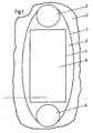
- Fig. 1 shows the area of a door in a section of a wall of a tower 2 of a wind turbine.
- the area 1 of the door or the door frame 3 has in the illustrated embodiment, for reasons of static reasons, a substantially oval contour.
- a framed by the door frame 3 door opening 4, which is closed with a door leaf 5, in this embodiment has a rectangular shape.
- air passage openings 6, 7 to aerate the tower, in particular to cool it with air.
- the air passage openings 6, 7 could for example, as in the selected embodiment, be circular and have a diameter of for example about 450 mm.
- a rectangular door opening 4 advantageously allows the use of a standard door.
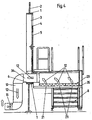
- Fig. 2 shows a schematic section through the foot of a tower 2 of a wind turbine.
- the tower 2 has a door with a door leaf 5 according to Fig. 1 on.
- Within the outer contour 1 of a door frame 3 is located in the door frame 3, an air passage opening 6 below the door panel 5.
- This passage opening 6 is also below and in the protection of a staircase 8, which leads to the door of the tower 2.
- Inside the tower 2 in the region of his foot is an electrical device 9, which is to temper, in particular to cool, for which a sufficient air flow and air exchange is ensured in an air cooling according to the invention.
- the air passage opening 6 via an air duct 10, for example a hose, with the electrical device 9 air conductively connected.
- a fan 11 is preferably used in the air duct 10, which sucks the air in the direction of arrows 12 through the air outlet opening 6 and the electrical device 9 feeds.
- the air can be collected after the electrical device 9 by a hood 13 and discharged through a further air duct 14 and with a further fan 15 through an air outlet opening 16 from the tower 2 to the outside.
- the air outlet opening 16 is preferably arranged on the side facing away from the air passage opening 6 of the tower 2.
- a weather protection 17 with slats 18 is also indicated by way of example in the drawing.
- the electrical device 9 may, for example, be a converter. At this point, however, it would also be possible to set up a transformer, for example, while an inverter could be located on the tower head in the nacelle of the wind energy plant. For example, a transformer could also be set up outside the tower 2 and, for example, cooled in its own transformer house.
- a filter device 20 can be seen.
- This filter device 20 is arranged below the stairs 8 in a protected and at the same time easily accessible area. It can for example consist of three plate-like juxtaposed filter cartridges 21, which are easily removable, interchangeable and cleanable. Within each filter cartridge 21, for example, a zig-zag folded filter material can be inserted.
- the arrangement of the filter device 20 with pointing down to the ground suction opening has the advantage that trapped particles in the filter device 20 after switching off the fan 11 at least partially automatically by gravity and possibly vibration from the filter device 20 fall down. The filter device 20 is thus self-cleaning.
- Fig. 3 shows a second embodiment of a ventilated tower base. Like components are denoted by the same reference numerals as In Fig. 2 ,
- the electrical device 9 for example, an inverter, located further up the tower 2, while at the very bottom of the tower 2, a further electrical device 22, for example, a transformer, is arranged Therefore, now the electrical device 22 with an air flow 12, which flows from the arranged below the door panel 5 air passage opening 6 to the air outlet opening 16, cooled.
- the air flow is preferably conveyed by a fan 15, which deviates from the in Fig. 3 shown position can be arranged directly on the transformer or the electrical device 22. Such an arrangement makes the assembly easier.
- the higher arranged device 9 is cooled by a further air flow 23.
- a ventilation duct 24 with a fan 25 to the electrical device 9.
- a hood 26 with a ventilation duct 27 with a fan 28 which leads to a further air outlet opening 29 and the air outlet opening 29 and Upper air passage opening 7 each have a weather protection 30, 31 with fins 32, 33.
- a filter device 36 can be introduced with filter cassettes 37 in front of the electrical device 9, wherein this filter is located inside the tower 2
- Fig. 4 shows a detail Fig. 2 in a staircase area of the tower base, but with a slightly different staircase designed 8. Same components are again denoted by the same reference numerals as in the preceding figures.
- the filter cassettes 21 could be provided, for example, a removable or hinged drip tray for dust and similar particles.
- a folding mechanism contributes while unfolding the weight of filter cartridges 21 and drip tray. An uncontrolled down falling filter cartridges 21 and drip tray can be prevented by the folding mechanism.
- Fig. 5 shows the tower 2 with transparent outer walls.
- the tower ventilation according to the invention serves to cool the provided in the foot of the tower 2 electrical equipment 9 such as the transformer 22.
- the located below the door panel 5 air passage opening 6 is disposed below the pedestal of the stairs 8.
- a filter box 60 is mounted on the outside of the tower 2 on the bottom side of the pedestal. The filter box 60 cleans from the outside sucked cooler air before passing through the passage opening 6 of floating particles, dust and the like.
- the transformer 22 is housed in an air-carrying transformer housing 61 and disposed slightly above the bottom of the foot of the tower 2.
- the sucked through the passage opening 6 air can be passed through an air duct 62 of the air-conducting transformer housing 61 under the transformer 22. From there, it flows into the interior of the transformer housing 61 past the transformer 22 and absorbs its heat at least in part.
- the heated by the heat absorption air accelerates in the transformer housing 61.
- the heated air is collected by a hood 13 and passed through the further air duct 14 to a turminnen ceremonial next to the passage opening 7 fan 63.
- the fan 63 blows the heated air from the located above the door panel 5 air passage opening 7 back out of the interior of the tower 2 into the open.
- the fan 63 in deviation to the representation in Fig. 5 be arranged directly on top of the hood 13 for ease of assembly.
- an exhaust box 70 On the outside of the air passage opening 7 is an exhaust box 70 according to Fig. 6 intended.
- the exhaust box 70 is closed at its outwardly facing end face and is bounded on the bottom side and bottom side of two differently long and curved strips 71, 72, between which two parallel to the ground extending air passage column 73 remain free.
- the air passage gaps 73 are covered by the longer bottom-side strip 72 and thus protected from rainfall.
- an air guide plate for dividing the flow to the two air passage column 73 may be provided in the interior of the exhaust box 70.
- Fig. 5a are the two air passage openings 6, 7 by one to the door frame 3 and on the other by the two outside the tower arranged filter boxes 71, 72 hidden
- the upper filter box 71 is connected upstream of the upper air passage opening 7 in the flow direction of the incoming air.
- the upper filter box 71 is openable to the ground down.
- filter cassettes 21 are embedded.
- the filter cassettes 21 are provided via a downwardly openable lid handle height above a pedestal of the staircase 8. The lid with the filter cassettes 21 can thus be opened down safely by the installer and the filter cassettes 21 can optionally be replaced or cleaned.
- the lower filter box 72 is also upstream in the flow direction of the lower air passage opening 6 and arranged below the pedestal of the staircase 8 Also, the lower filter box 72 is equipped with a folding mechanism for the lower filter cassettes 21, which allows the filter cassettes 21 down safely means of Open the covers and replace or clean.
- the entering through the lower air passage opening 6 through the lower filter box 72 cleaned air is sucked by a fan 15 through the air duct 10 into the interior of the tower 2 and sweeps it to the electrical devices 22, for example.
- a transformer passing and cools them.
- the waste heat absorbing air is sucked through the arranged in this example above an intermediate floor fan 15 through the other air duct 14 and blown out of the air outlet opening 16 to the outside.
- Air filter box 71 filtered air flows through the further air duct 74, conveyed by a fan 25, to the electrical device 9 over.
- the structure corresponds to the principle in Fig. 3 shown construction. However, there is no filter with filter box in the interior of the tower 3, but a filter box 71 with filter 21 is connected upstream of the tower of the upper air passage opening 7.
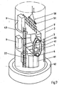
- Fig. 7 shows the tower 2 in a perspective view with removed door frame 3, but with the air passage openings 6, 7th
- the transformer 22 and the area 1 are designed and matched in size to one another that the transformer 22 can be introduced through the area 1 with the door frame 3 removed in the tower 2 and later applied again.
- the transformer 22 can by the inventive targeted ventilation, as shown for example in Fig. 5 is designed to be smaller than usual, and so small that it fits after removing the detachable door frame 3 through the area 1 therethrough.
- the targeted ventilation is achieved by the door frame 3 according to the invention and the air passage openings 6, 7, possible air flow and / or by the air-conducting transformer housing 61.
- the transformer housing 61 can be dismantled for the transport of the transformer 22 and preferably disassembled, so that also its parts fit through the area 1.
- the transformer 22 can by an intermediate bottom 40 according to Fig. 7 be raised or lowered in the tower 2.
- a loading flap or removable running plates 41 can be let into the intermediate floor 40 in order to be opened.
- the lifting of the transformer 22 is done with a hoist 50, which can preferably be suspended from a (not shown) flange of the lowermost tower segment of the tower 2 inside the tower 2.
- fastening points for striking the hoist 50 may also be provided in the tower wall.
- the transformer 22 is preferably on a horizontal load bar 51 of the hoist 50 according to Fig. 8 screwed or lashed.
- the tabs 52 may be equipped with rollers 53 in the manner of a trolley to allow a horizontal displacement of the load beam 51 hanging transformer 22 on the load bar 51 along.
- the rollers 53 may, for example, run in a double T-shape of the load beam 51, such as Fig. 9 shows.
- the tabs 52 are secured by means of fixing bolts 54 on the load beam 51 against slipping.
- the transformer 22 can be fastened by lugs 52 arranged on the eyelets 55 on the tabs 52 for mounting.
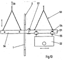
- the load beam 51 can, as in Fig. 10 shown schematically, be extended through the door opening 1 through to a load bridge to the outside, so that the transformer 22 can be moved out of the tower 2 or in the tower 2 into it.
- the outer end of the load bridge can be supported outside of the tower 2, for example, with a support on the ground or be suspended by means of a (not shown) crane 58 at the right height.
- the load bridge comprises the load bar 51 provided in the interior of the tower 2 and a load bar 56 provided outside the tower.
- the load bar 51 provided in the tower 2 and the load bar 56 provided outside the tower 2 are for displacing the transformer 22 by means of the tabs 52 along the load bridge temporarily positionally fixed to each other by a connecting member 57 connectable and form by their fixed connection, the load bridge.
- the transformer 22, its housing parts and also additional electrical devices 9 in Fig. 7 can be lifted or lowered by the intermediate bottom 40 when recorded Laufplatten 41.
- the transformer 22 and the electrical devices 9 can settle once on a foundation plate 42 of the tower 2 and then the electrical equipment 9, for example, with the growth of the tower 2 in its construction by the intermediate floor 40, on the intermediate floor level or raise a higher level.
- At least one intermediate floor 40 in the tower 2 may in particular also be designed as a partial floor 43 or gallery, in order to allow a vertical path in the interior of the tower 2 past this partial floor 43.
Landscapes
- Engineering & Computer Science (AREA)
- General Engineering & Computer Science (AREA)
- Life Sciences & Earth Sciences (AREA)
- Sustainable Development (AREA)
- Sustainable Energy (AREA)
- Chemical & Material Sciences (AREA)
- Combustion & Propulsion (AREA)
- Mechanical Engineering (AREA)
- Architecture (AREA)
- Structural Engineering (AREA)
- Civil Engineering (AREA)
- Physics & Mathematics (AREA)
- Thermal Sciences (AREA)
- Cooling Or The Like Of Electrical Apparatus (AREA)
- Ventilation (AREA)
- Specific Sealing Or Ventilating Devices For Doors And Windows (AREA)
- Patch Boards (AREA)
- Wing Frames And Configurations (AREA)
- Door And Window Frames Mounted To Openings (AREA)
- Wind Motors (AREA)
Claims (14)
- Tour d'éolienne, munie d'une porte pour pénétrer à l'intérieur de la tour, comprenant
un dormant de porte (3) qui présente une baie de porte fermée de préférence par un vantail de porte (5) et un transformateur (22),
le dormant de porte (3) présentant au moins une ouverture de passage d'air (6, 7), en particulier une ouverture d'entrée d'air pour refroidir le transformateur (22) disposée dans le socle de la tour (2),
caractérisée en ce qu'un contour extérieur du dormant de porte (3) délimite une zone (1) dans une paroi de la tour (2)
et le dormant de porte (3) est démontable
et le transformateur (22) et la zone (1) sont conçues et adaptées mutuellement en termes de dimensions de manière telle que le transformateur (22) puisse être introduite et, ultérieurement, retirée de la tour (2) en passant par la zone (1), uniquement lorsque le dormant de porte (3) est démonté. - Tour selon la revendication 1,
caractérisée en ce que l'ouverture de passage d'air (6, 7) est disposée au dessous de la baie de porte (4). - Tour selon la revendication 1 ou 2,
caractérisée en ce que le dormant de porte (3) présente un contour extérieur sensiblement ovale et la baie de porte (4) a une forme sensiblement rectangulaire. - Tour selon une des revendications précédentes,
caractérisée en ce que pour la sortie de l'air, il est prévu au moins un dispositif d'aspiration (15). - Tour selon une des revendications précédentes, munie d'une porte pour pénétrer à l'intérieur de la tour et d'un escalier (8) menant à la porte et situé à l'extérieur de la tour,
caractérisée en ce qu'au moins un dispositif de filtrage (21) d'air est installé sous l'escalier (8). - Tour selon une des revendications précédentes,
caractérisée en ce que pour équilibrer la température d'une installation à équilibrer, disposée de préférence au-dessus du niveau de la porte, à l'intérieur de la tour, le dormant de porte (3) présente au moins une ouverture de passage d'air (6, 7) au-dessus de la baie de porte (4). - Tour selon la revendication 6,
caractérisée en ce qu'au moins un dispositif de filtrage, situé à l'intérieur de la tour, est placé en aval de l'ouverture de passage d'air (6, 7) disposée au-dessus de la baie de porte (4). - Dormant pour une porte d'une tour d'éolienne selon une des revendications précédentes 1 à 7, qui présente une baie de porte fermée de préférence par un vantail de porte,
comprenant au moins une ouverture de passage d'air (6, 7) pour refroidir un transformateur (22) disposée dans le socle de la tour (2),
un contour extérieur du dormant de porte (3) délimitant une zone (1) dans une paroi de la tour (2),
caractérisé en ce que le dormant de porte (3) est démontable et le transformateur (22) et la zone (1) sont conçues et adaptées mutuellement en termes de dimensions de manière telle que le transformateur (22) puisse être introduite et, ultérieurement, retirée de la tour (2) en passant par la zone (1), uniquement lorsque le dormant de porte (3) est démonté. - Dormant de porte selon la revendication 8,
caractérisé en ce que l'ouverture de passage d'air (6, 7) est disposée au dessous de la baie de porte (4). - Dormant de porte selon la revendication 8 ou 9,
caractérisé en ce que le dormant de porte (3) présente un contour extérieur sensiblement ovale et la baie de porte (4) a une forme sensiblement rectangulaire. - Eolienne comprenant une tour selon une des revendications 1 à 7, munie d'une porte pour pénétrer à l'intérieur de la tour et d'un escalier (8) menant à la porte et situé à l'extérieur de la tour,
caractérisée en ce qu'au moins un dispositif de filtrage (21) d'air est installé sous l'escalier (8). - Eolienne selon la revendication 11,
caractérisée en ce que le dispositif de filtrage (21) est installé en amont d'une ouverture de passage d'air (6, 7) disposée au-dessous de la baie de porte (4). - Eolienne selon la revendication 12,
caractérisée en ce que le passage d'air formé par le dispositif de filtrage (21) et l'ouverture de passage d'air (6, 7) est associé à au moins une installation électrique (9), de préférence à un convertisseur et/ou un transformateur, afin d'opérer un équilibrage de la température, notamment un refroidissement. - Eolienne selon une des revendications 11 à 13,
caractérisée en ce que pour l'équilibrage de la température d'un dispositif à équilibrer, installé de préférence au-dessus du niveau de la porte, à l'intérieur de la tour, le dormant de porte (3) présente au moins une ouverture de passage d'air (6, 7) au-dessus de la baie de porte (4).
Applications Claiming Priority (4)
| Application Number | Priority Date | Filing Date | Title |
|---|---|---|---|
| DE102008006766 | 2008-01-30 | ||
| DE102008012664A DE102008012664A1 (de) | 2008-01-30 | 2008-03-05 | Windenergieanlage und ein Turm oder Turmsegment und eine Türzarge dafür |
| DE102008037768A DE102008037768A1 (de) | 2008-01-30 | 2008-08-14 | Windenergieanlage und ein Turm oder Turmsegment und eine Türzarge dafür |
| PCT/DE2009/000099 WO2009094991A2 (fr) | 2008-01-30 | 2009-01-28 | Éolienne et tour ou segment de tour, et dormant de porte correspondant |
Publications (4)
| Publication Number | Publication Date |
|---|---|
| EP2247853A2 EP2247853A2 (fr) | 2010-11-10 |
| EP2247853B1 EP2247853B1 (fr) | 2012-02-22 |
| EP2247853B8 EP2247853B8 (fr) | 2012-04-11 |
| EP2247853B2 true EP2247853B2 (fr) | 2017-09-27 |
Family
ID=40822248
Family Applications (1)
| Application Number | Title | Priority Date | Filing Date |
|---|---|---|---|
| EP09706104.8A Active EP2247853B2 (fr) | 2008-01-30 | 2009-01-28 | Tour d'éolienne ou segment dedit tour d'éolienne avec une porte ayant un cadre de porte |
Country Status (8)
| Country | Link |
|---|---|
| US (2) | US9347236B2 (fr) |
| EP (1) | EP2247853B2 (fr) |
| CN (1) | CN101970869B (fr) |
| AT (1) | ATE546648T1 (fr) |
| DE (2) | DE102008012664A1 (fr) |
| DK (1) | DK2247853T4 (fr) |
| ES (1) | ES2382146T5 (fr) |
| WO (1) | WO2009094991A2 (fr) |
Families Citing this family (41)
| Publication number | Priority date | Publication date | Assignee | Title |
|---|---|---|---|---|
| DE102008012664A1 (de) * | 2008-01-30 | 2009-08-06 | Repower Systems Ag | Windenergieanlage und ein Turm oder Turmsegment und eine Türzarge dafür |
| DE102008019271A1 (de) | 2008-04-16 | 2009-10-22 | Kenersys Gmbh | Windkraftanlage mit verbesserter Kühlluftführung |
| DE102008021498A1 (de) * | 2008-04-29 | 2009-11-05 | Repower Systems Ag | Verfahren zur Fertigung eines Blattanschlusses eines Rotorblatts, ein Blattanschluss und ein Befestigungselement für einen Blattanschluss |
| JP5970189B2 (ja) | 2009-01-29 | 2016-08-17 | ノルドマルク・アルツナイミッテル・ゲゼルシヤフト・ミト・ベシュレンクテル・ハフツング・ウント・コンパニー・コマンデイトゲゼルシヤフト | 医薬調製物 |
| US7999407B2 (en) * | 2009-09-01 | 2011-08-16 | Raymond Saluccio | Air conditioning cover connecting exhaust to turbine |
| JP5318740B2 (ja) * | 2009-12-11 | 2013-10-16 | 株式会社日立製作所 | 洋上風車 |
| JP5595057B2 (ja) * | 2010-02-08 | 2014-09-24 | 三菱重工業株式会社 | 風力発電装置 |
| EP2535575A4 (fr) * | 2010-02-08 | 2014-04-30 | Mitsubishi Heavy Ind Ltd | Dispositif generateur d'energie eolienne |
| US11223319B2 (en) | 2010-07-16 | 2022-01-11 | Strategic Solar Energy, Llc | Protection of electrical components in solar energy shade structure |
| US8825500B2 (en) * | 2010-07-16 | 2014-09-02 | Strategic Solar Energy, Llc | Solar energy collecting systems and methods |
| US10700633B2 (en) * | 2010-07-16 | 2020-06-30 | Strategic Solar Energy, Llc | Protection of electrical components in solar energy shade structure |
| KR101223222B1 (ko) * | 2010-07-19 | 2013-01-17 | 주식회사 평산 | 풍력 타워용 도어 프레임 제작 공법 |
| US8038398B2 (en) * | 2010-10-06 | 2011-10-18 | General Electric Company | System and method of distributing air within a wind turbine |
| US8171674B2 (en) | 2010-12-16 | 2012-05-08 | General Electric Company | Doorway for a wind turbine tower |
| JP5284386B2 (ja) * | 2011-02-21 | 2013-09-11 | 株式会社日立産機システム | 風力発電設備 |
| ES2484697T3 (es) * | 2011-09-09 | 2014-08-12 | Areva Wind Gmbh | Torre de turbina eólica con refuerzo de muro de torre de guía de aire circunferencial |
| DK2568169T4 (da) | 2011-09-09 | 2022-01-10 | Siemens Gamesa Renewable Energy Deutschland Gmbh | Vindmølle med tårnklimatiseringssystem ved anvendelse af udeluft |
| CN102434408B (zh) * | 2011-12-23 | 2015-07-22 | 北京金风科创风电设备有限公司 | 风力发电机组塔架门洞及其设计方法 |
| DE102012202979A1 (de) * | 2012-02-28 | 2013-08-29 | Wobben Properties Gmbh | Windenergieanlage |
| CN102828921B (zh) * | 2012-09-11 | 2014-07-09 | 华锐风电科技(集团)股份有限公司 | 风力发电机组的塔筒及风力发电机组 |
| KR101997265B1 (ko) * | 2012-11-22 | 2019-07-08 | 두산중공업 주식회사 | 풍력발전기 타워와 타워를 갖는 풍력발전기 |
| DK2808543T3 (en) * | 2013-05-28 | 2017-12-18 | Siemens Ag | dehumidification |
| CN103498766A (zh) * | 2013-10-12 | 2014-01-08 | 广东明阳风电产业集团有限公司 | 一种风力发电机组塔基通风散热结构 |
| EP2933481B1 (fr) * | 2014-04-15 | 2019-01-09 | Areva Wind GmbH | Conduit d'air pour éolienne, éolienne, procédé de fabrication d'un conduit d'air et procédé de modernisation d'une installation éolienne avec un conduit d'air |
| JP6383562B2 (ja) * | 2014-04-23 | 2018-08-29 | 株式会社日立製作所 | 風力発電設備 |
| GB2532432B (en) | 2014-11-18 | 2021-09-08 | Arm Ip Ltd | Methods of accessing a remote resource from a data processing device |
| CN105781900A (zh) * | 2014-12-25 | 2016-07-20 | 浙江运达风电股份有限公司 | 一种风力发电机组及通风散热系统 |
| DK178587B1 (en) * | 2015-02-02 | 2016-07-25 | Vestas Wind Sys As | Access panel for a wind turbine tower and method for securing same |
| DK178586B1 (en) | 2015-02-02 | 2016-07-25 | Vestas Wind Sys As | Wind turbine access panel and method for securing same |
| US9782710B2 (en) | 2015-07-01 | 2017-10-10 | General Electric Company | Multi-sided ventilation assembly for wind turbine tower access door |
| DE102015212321A1 (de) * | 2015-07-01 | 2017-01-05 | Wobben Properties Gmbh | Windenergieanlage und Kühlvorrichtung für eine Windenergieanlage |
| CN113738586A (zh) * | 2015-08-31 | 2021-12-03 | 西门子歌美飒可再生能源有限公司 | 具有混凝土底座的设备塔架 |
| DE102015217035A1 (de) * | 2015-09-04 | 2017-03-09 | Wobben Properties Gmbh | Windenergieanlage und Verfahren zum Steuern einer Kühlung einer Windenergieanlage |
| DE102015122855A1 (de) * | 2015-12-28 | 2017-06-29 | Wobben Properties Gmbh | Windenergieanlage und Kühlvorrichtung für eine Windenergieanlage |
| CN106150929B (zh) * | 2016-08-05 | 2020-12-01 | 江苏金风科技有限公司 | 风力发电机组塔底冷却装置及控制方法 |
| CN109464865B (zh) * | 2018-12-29 | 2021-07-23 | 北京金风科创风电设备有限公司 | 过滤装置、塔筒门、塔筒及塔筒门的测试方法 |
| US10954922B2 (en) | 2019-06-10 | 2021-03-23 | General Electric Company | System and method for cooling a tower of a wind turbine |
| EP3825550B1 (fr) * | 2019-11-21 | 2023-08-23 | Wobben Properties GmbH | Segment de tour et procédé de fabrication |
| EP4215744B1 (fr) * | 2022-01-20 | 2025-07-23 | Siemens Gamesa Renewable Energy Innovation & Technology S.L. | Agencement de porte pour une éolienne, dispositif de verrouillage de porte et éolienne |
| CN115263675A (zh) * | 2022-07-29 | 2022-11-01 | 中国华电科工集团有限公司 | 一种储能设备散热系统 |
| CN115523109A (zh) * | 2022-09-16 | 2022-12-27 | 浙江运达风电股份有限公司 | 一种风电机组塔筒散热系统 |
Family Cites Families (62)
| Publication number | Priority date | Publication date | Assignee | Title |
|---|---|---|---|---|
| US2506978A (en) * | 1947-05-07 | 1950-05-09 | Steve Kinchem | Door and window structure |
| US3159093A (en) * | 1961-10-09 | 1964-12-01 | Morton M Rosenfeld | Door structure |
| US3698308A (en) * | 1970-05-28 | 1972-10-17 | Joseph Navara | Filter system for windows |
| US3768016A (en) * | 1972-06-01 | 1973-10-23 | Pittsburgh Des Moines Steel | Modular, prefabricated, integrated communications relay tower |
| DE3504840A1 (de) * | 1985-02-13 | 1986-08-14 | Stahlrohrbau GmbH, 8500 Nürnberg | Versteifungsvorrichtung fuer einen stahlrohrmast |
| WO1988002805A1 (fr) | 1986-10-14 | 1988-04-21 | John George Hamilton | Dispositif de ventilation |
| US4915590A (en) * | 1987-08-24 | 1990-04-10 | Fayette Manufacturing Corporation | Wind turbine blade attachment methods |
| DE59104696D1 (de) * | 1990-12-08 | 1995-03-30 | Knecht Filterwerke Gmbh | Filtereinsatz für insbesondere Gasfilter. |
| JP3916724B2 (ja) * | 1997-05-26 | 2007-05-23 | ミサワホーム株式会社 | 収納構造 |
| JP3679608B2 (ja) * | 1998-05-14 | 2005-08-03 | 三洋電機株式会社 | 空気調和機の固定装置 |
| JP2000283018A (ja) * | 1999-03-30 | 2000-10-10 | Fuji Heavy Ind Ltd | 水平軸風車及び該水平軸風車の建設方法 |
| DK1057770T3 (da) * | 1999-06-03 | 2006-02-20 | D H Blattner & Sons Inc | På föringsskinner klatrende löfteplatform og fremgangsmåde |
| EP1200733B2 (fr) * | 1999-07-14 | 2012-02-15 | Aloys Wobben | Eolienne a circuit de refroidissement ferme |
| JP3500113B2 (ja) * | 2000-07-21 | 2004-02-23 | 株式会社フォリス | 開き式ドア構造 |
| US6470645B1 (en) * | 2000-11-09 | 2002-10-29 | Beaird Industries, Inc. | Method for making and erecting a wind tower |
| US6532700B1 (en) * | 2000-11-09 | 2003-03-18 | Beaird Industries, Inc. | Flange with cut for wind tower |
| DE10127451C5 (de) * | 2001-06-07 | 2016-09-01 | Aloys Wobben | Verfahren zur Steuerung einer Windenergieanlage |
| DE10152550A1 (de) * | 2001-10-24 | 2003-05-08 | Gen Electric | Bauelement |
| DE60312816T2 (de) | 2002-01-11 | 2008-02-07 | Fiberline A/S | Verfahren zur herstellung eines faserverstärkten lasttragenden elements |
| DK200200178A (da) * | 2002-02-06 | 2003-08-07 | Vestas Wind Sys As | Ophængningsmidler til vindturbinetårne |
| DE10205373B4 (de) * | 2002-02-09 | 2007-07-19 | Aloys Wobben | Brandschutz |
| NL1020481C1 (nl) * | 2002-04-26 | 2003-10-31 | Oxycell Holding Bv | Enthalpiewisselaar, uitgevoerd als kozijnstijl. |
| AU2003267421B2 (en) * | 2002-10-01 | 2009-12-17 | General Electric Company | Modular kit for a wind turbine tower |
| EP1592886B1 (fr) * | 2003-02-01 | 2015-10-14 | Wobben Properties GmbH | Procede d'installation d'un dispositif eolien et dispositif eolien |
| US20040172881A1 (en) * | 2003-03-04 | 2004-09-09 | Takuji Minami | Door system opening on both the left and right sides |
| EP1606514B1 (fr) | 2003-03-19 | 2007-11-07 | Vestas Wind System A/S | Procede de construction de grandes tours destinees a des turbines eoliennes |
| US7934585B2 (en) * | 2003-04-15 | 2011-05-03 | Vestas Wind Systems A/S | Method of servicing the outer components of a wind turbine such as the wind turbine blades and the tower with a work platform and work platform |
| EP1486415A1 (fr) | 2003-06-12 | 2004-12-15 | SSP Technology A/S | Pale de turbine éolienne et procédé de fabrication de la base d'une pale d'éolienne |
| EP1486637B1 (fr) * | 2003-06-12 | 2009-08-05 | Lidartech Co., Ltd. | Fenêtre avec dispositif de ventilation |
| DE60311894T2 (de) * | 2003-08-09 | 2007-11-22 | General Electric Co. | Turmfundament, insbesondere für eine windenergieturbine |
| US7529195B2 (en) * | 2004-07-30 | 2009-05-05 | Fortiusone, Inc. | System and method of mapping and analyzing vulnerabilities in networks |
| US7448169B2 (en) * | 2004-08-11 | 2008-11-11 | Beaird Company, Ltd. | Method for constructing and erecting a tower with ballistic resistant enclosure |
| DE102004054246A1 (de) | 2004-09-27 | 2006-04-06 | Carl Freudenberg Kg | Anordnung für ein plattenförmiges Filterelement in einem Gasfiltergehäuse |
| ATE471453T1 (de) * | 2004-11-10 | 2010-07-15 | Vestas Wind Sys As | Turmteil für eine windturbine, verfahren zur herstellung eines turmteils und verwendungen davon |
| DE102004056340B4 (de) * | 2004-11-22 | 2010-11-18 | Repower Systems Ag | Vorrichtung und Verfahren zur Montage und/oder Demontage eines Bauteils einer Windkraftanlage |
| AU2004325168A1 (en) * | 2004-11-23 | 2006-06-01 | Vestas Wind Systems A/S | A wind turbine, a method for assembling and handling the wind turbine and uses hereof |
| DE102004061391B4 (de) * | 2004-12-21 | 2010-11-11 | Repower Systems Ag | Temperaturregelung in einer Windenergieanlage |
| DE102005014868A1 (de) * | 2005-03-30 | 2006-10-05 | Repower Systems Ag | Offshore-Windenergieanlage mit rutschfesten Füßen |
| JP4277316B2 (ja) * | 2005-03-30 | 2009-06-10 | 東海ゴム工業株式会社 | 防振装置 |
| US7360340B2 (en) * | 2005-04-12 | 2008-04-22 | Grundman Curtis M | Means for securing the lower end of a wind turbine tower to a foundation |
| US7387497B2 (en) * | 2005-04-12 | 2008-06-17 | Cone Matthew D | Adapter |
| JP4405448B2 (ja) * | 2005-08-30 | 2010-01-27 | 本田技研工業株式会社 | 能動型防振支持装置 |
| US7735290B2 (en) * | 2005-10-13 | 2010-06-15 | General Electric Company | Wind turbine assembly tower |
| US7762037B2 (en) * | 2005-11-18 | 2010-07-27 | General Electric Company | Segment for a tower of a wind energy turbine and method for arranging operating components of a wind energy turbine in a tower thereof |
| EP1987215A1 (fr) * | 2006-02-20 | 2008-11-05 | Vestas Wind Systems A/S | Tour de turbine eolienne, turbine eolienne et procede d'assemblage d'une tour de turbine eolienne |
| DE202006003628U1 (de) * | 2006-03-06 | 2006-06-14 | Gervink, Gregor | Feuchtigkeits-Schutz-Schürze für ein Bauwerk |
| CN101401254A (zh) * | 2006-03-20 | 2009-04-01 | 艾利森电话股份有限公司 | 筒状电信塔 |
| DK2002120T3 (da) | 2006-03-25 | 2010-03-15 | Clipper Windpower Technology Inc | Varmeadministrationsanlæg til en vindturbine |
| DE102006021982C5 (de) * | 2006-05-10 | 2010-10-07 | Repower Systems Ag | Gestaffelt abschaltbarer Windpark |
| US7650721B2 (en) * | 2006-06-16 | 2010-01-26 | Nevins Robert L | Window for absorbing sunlight heat in warm weather that otherwise would flow uncontrolled therethrough and discharging the sunlight heat to the atmosphere while permitting relatively unobstructed vision therethrough and passing the sunlight heat in cold weather therethrough for thermal warming |
| CN101105081A (zh) * | 2006-07-11 | 2008-01-16 | 程新生 | 风能大厦 |
| WO2008042611A2 (fr) * | 2006-09-29 | 2008-04-10 | Centocor, Inc. | Procédé permettant d'utiliser des antagonistes il-6 avec la mitoxantrone pour traiter le cancer de la prostate |
| DE102006054666B4 (de) * | 2006-11-17 | 2010-01-14 | Repower Systems Ag | Schwingungsdämpfung einer Windenergieanlage |
| JP4243290B2 (ja) * | 2006-11-21 | 2009-03-25 | 本田技研工業株式会社 | 能動型防振支持装置 |
| DE102007014863A1 (de) * | 2007-03-26 | 2008-10-02 | Repower Systems Ag | Verfahren zum Betreiben einer Windenergieanlage |
| DE102008012664A1 (de) | 2008-01-30 | 2009-08-06 | Repower Systems Ag | Windenergieanlage und ein Turm oder Turmsegment und eine Türzarge dafür |
| DE102008019271A1 (de) * | 2008-04-16 | 2009-10-22 | Kenersys Gmbh | Windkraftanlage mit verbesserter Kühlluftführung |
| DE102008021498A1 (de) * | 2008-04-29 | 2009-11-05 | Repower Systems Ag | Verfahren zur Fertigung eines Blattanschlusses eines Rotorblatts, ein Blattanschluss und ein Befestigungselement für einen Blattanschluss |
| DE102008022383B4 (de) * | 2008-05-06 | 2016-01-21 | Senvion Gmbh | Positionierung eines Rotors einer Windenergieanlage |
| DE102008049016A1 (de) | 2008-09-25 | 2010-04-15 | Repower Systems Ag | Rotorblatt mit einem Gurt mit einer in Längsrichtung abnehmenden Breite, Verfahren zur Herstellung des Rotorblattes und Verlegehilfe für Gelegebänder des Gurtes |
| EP2535575A4 (fr) * | 2010-02-08 | 2014-04-30 | Mitsubishi Heavy Ind Ltd | Dispositif generateur d'energie eolienne |
| US8171674B2 (en) * | 2010-12-16 | 2012-05-08 | General Electric Company | Doorway for a wind turbine tower |
-
2008
- 2008-03-05 DE DE102008012664A patent/DE102008012664A1/de not_active Withdrawn
- 2008-08-14 DE DE102008037768A patent/DE102008037768A1/de not_active Ceased
-
2009
- 2009-01-28 EP EP09706104.8A patent/EP2247853B2/fr active Active
- 2009-01-28 WO PCT/DE2009/000099 patent/WO2009094991A2/fr not_active Ceased
- 2009-01-28 US US12/735,554 patent/US9347236B2/en active Active
- 2009-01-28 AT AT09706104T patent/ATE546648T1/de active
- 2009-01-28 DK DK09706104.8T patent/DK2247853T4/en active
- 2009-01-28 ES ES09706104.8T patent/ES2382146T5/es active Active
- 2009-01-28 CN CN2009801015961A patent/CN101970869B/zh active Active
-
2014
- 2014-02-27 US US14/191,836 patent/US9175491B2/en active Active
Also Published As
| Publication number | Publication date |
|---|---|
| DE102008012664A1 (de) | 2009-08-06 |
| US9175491B2 (en) | 2015-11-03 |
| WO2009094991A3 (fr) | 2010-08-12 |
| CN101970869B (zh) | 2013-06-19 |
| CN101970869A (zh) | 2011-02-09 |
| US20100308596A1 (en) | 2010-12-09 |
| WO2009094991A2 (fr) | 2009-08-06 |
| ES2382146T5 (es) | 2017-12-07 |
| DK2247853T3 (da) | 2012-05-07 |
| DE102008037768A1 (de) | 2009-08-06 |
| ES2382146T3 (es) | 2012-06-05 |
| EP2247853B8 (fr) | 2012-04-11 |
| EP2247853B1 (fr) | 2012-02-22 |
| US20140237937A1 (en) | 2014-08-28 |
| DK2247853T4 (en) | 2017-12-04 |
| US9347236B2 (en) | 2016-05-24 |
| ATE546648T1 (de) | 2012-03-15 |
| EP2247853A2 (fr) | 2010-11-10 |
Similar Documents
| Publication | Publication Date | Title |
|---|---|---|
| EP2247853B2 (fr) | Tour d'éolienne ou segment dedit tour d'éolienne avec une porte ayant un cadre de porte | |
| DE102004064007B4 (de) | Windenergieanlage mit einer Generatorkühlung | |
| DE102010011365B4 (de) | Wetterschutz für Arbeitsbühnen an Propellerblättern von Windkraftanlagen | |
| DE2605941C3 (de) | Gehäuse | |
| EP2318251B1 (fr) | Véhicule ferroviaire pouvant être commuté entre un mode hiver et un mode été | |
| DE10060181B4 (de) | Laubbläser | |
| DE102009051052A1 (de) | Motorabdeckung für eine selbstfahrende landwirtschaftliche Erntemaschine | |
| EP1530109B1 (fr) | Ventilateur et methode pour commander le flux d'air d'un ventilateur | |
| DE2156189A1 (de) | Dachentluefter | |
| DE102010014787B4 (de) | Solarthermische Anlage | |
| DE19519815C2 (de) | Transportable Farbspritzkabine in Form eines Zelts | |
| DE202008017906U1 (de) | Leitflächenlüfter für ein Dach eines Gebäudes | |
| DE102006043936B4 (de) | Belüftung einer Windenergieanlage | |
| DE1228640B (de) | Luftgekuehlter Waermeaustauscher, dessen Axialluefter auf einem Stuetzbock gelagert ist | |
| DE7836644U1 (de) | Dachluefter | |
| DE3246341C2 (de) | Vorrichtung zum Waschen von Gasen, vornehmlich zum Reinigen, Befeuchten und Kühlen von Luft | |
| DE1604145B1 (de) | Dach-Entlueftungsvorrichtung | |
| DE1604145C (de) | Dach Entlüftungsvorrichtung | |
| DE202010007071U1 (de) | Mobiler aufblasbarer und stapelfähiger Lichtturm mit geschlossenem Gehäuse und integriertem Schubfach | |
| CH699622B1 (de) | Wärmepumpe. | |
| WO2007060158A1 (fr) | Enceinte pour chambre de combustion de type silo d'une turbine a gaz | |
| DE202016105815U1 (de) | Vorrichtung zur Trocknung von Trocknungsgut | |
| DE1771506A1 (de) | Kokskuchenfuehrungswagen mit Fanghaube fuer den emittierten Staub | |
| WO1996020792A1 (fr) | Cabine de peinture au pistolet transportable se presentant sous forme de tente | |
| DE202015101206U1 (de) | Mobile Feuerungsanlage |
Legal Events
| Date | Code | Title | Description |
|---|---|---|---|
| PUAI | Public reference made under article 153(3) epc to a published international application that has entered the european phase |
Free format text: ORIGINAL CODE: 0009012 |
|
| 17P | Request for examination filed |
Effective date: 20100722 |
|
| AK | Designated contracting states |
Kind code of ref document: A2 Designated state(s): AT BE BG CH CY CZ DE DK EE ES FI FR GB GR HR HU IE IS IT LI LT LU LV MC MK MT NL NO PL PT RO SE SI SK TR |
|
| AX | Request for extension of the european patent |
Extension state: AL BA RS |
|
| 17Q | First examination report despatched |
Effective date: 20110426 |
|
| DAX | Request for extension of the european patent (deleted) | ||
| GRAP | Despatch of communication of intention to grant a patent |
Free format text: ORIGINAL CODE: EPIDOSNIGR1 |
|
| GRAS | Grant fee paid |
Free format text: ORIGINAL CODE: EPIDOSNIGR3 |
|
| GRAA | (expected) grant |
Free format text: ORIGINAL CODE: 0009210 |
|
| AK | Designated contracting states |
Kind code of ref document: B1 Designated state(s): AT BE BG CH CY CZ DE DK EE ES FI FR GB GR HR HU IE IS IT LI LT LU LV MC MK MT NL NO PL PT RO SE SI SK TR |
|
| REG | Reference to a national code |
Ref country code: GB Ref legal event code: FG4D Free format text: NOT ENGLISH |
|
| REG | Reference to a national code |
Ref country code: CH Ref legal event code: EP |
|
| REG | Reference to a national code |
Ref country code: AT Ref legal event code: REF Ref document number: 546648 Country of ref document: AT Kind code of ref document: T Effective date: 20120315 |
|
| RAP2 | Party data changed (patent owner data changed or rights of a patent transferred) |
Owner name: REPOWER SYSTEMS SE |
|
| REG | Reference to a national code |
Ref country code: IE Ref legal event code: FG4D Free format text: LANGUAGE OF EP DOCUMENT: GERMAN |
|
| REG | Reference to a national code |
Ref country code: DE Ref legal event code: R096 Ref document number: 502009002849 Country of ref document: DE Effective date: 20120419 |
|
| REG | Reference to a national code |
Ref country code: DK Ref legal event code: T3 |
|
| REG | Reference to a national code |
Ref country code: ES Ref legal event code: FG2A Ref document number: 2382146 Country of ref document: ES Kind code of ref document: T3 Effective date: 20120605 |
|
| REG | Reference to a national code |
Ref country code: AT Ref legal event code: HC Ref document number: 546648 Country of ref document: AT Kind code of ref document: T Owner name: REPOWER SYSTEMS SE, DE Effective date: 20120514 |
|
| REG | Reference to a national code |
Ref country code: NL Ref legal event code: VDEP Effective date: 20120222 |
|
| LTIE | Lt: invalidation of european patent or patent extension |
Effective date: 20120222 |
|
| PG25 | Lapsed in a contracting state [announced via postgrant information from national office to epo] |
Ref country code: NL Free format text: LAPSE BECAUSE OF FAILURE TO SUBMIT A TRANSLATION OF THE DESCRIPTION OR TO PAY THE FEE WITHIN THE PRESCRIBED TIME-LIMIT Effective date: 20120222 Ref country code: IS Free format text: LAPSE BECAUSE OF FAILURE TO SUBMIT A TRANSLATION OF THE DESCRIPTION OR TO PAY THE FEE WITHIN THE PRESCRIBED TIME-LIMIT Effective date: 20120622 Ref country code: LT Free format text: LAPSE BECAUSE OF FAILURE TO SUBMIT A TRANSLATION OF THE DESCRIPTION OR TO PAY THE FEE WITHIN THE PRESCRIBED TIME-LIMIT Effective date: 20120222 Ref country code: NO Free format text: LAPSE BECAUSE OF FAILURE TO SUBMIT A TRANSLATION OF THE DESCRIPTION OR TO PAY THE FEE WITHIN THE PRESCRIBED TIME-LIMIT Effective date: 20120522 Ref country code: HR Free format text: LAPSE BECAUSE OF FAILURE TO SUBMIT A TRANSLATION OF THE DESCRIPTION OR TO PAY THE FEE WITHIN THE PRESCRIBED TIME-LIMIT Effective date: 20120222 |
|
| PG25 | Lapsed in a contracting state [announced via postgrant information from national office to epo] |
Ref country code: FI Free format text: LAPSE BECAUSE OF FAILURE TO SUBMIT A TRANSLATION OF THE DESCRIPTION OR TO PAY THE FEE WITHIN THE PRESCRIBED TIME-LIMIT Effective date: 20120222 Ref country code: LV Free format text: LAPSE BECAUSE OF FAILURE TO SUBMIT A TRANSLATION OF THE DESCRIPTION OR TO PAY THE FEE WITHIN THE PRESCRIBED TIME-LIMIT Effective date: 20120222 Ref country code: GR Free format text: LAPSE BECAUSE OF FAILURE TO SUBMIT A TRANSLATION OF THE DESCRIPTION OR TO PAY THE FEE WITHIN THE PRESCRIBED TIME-LIMIT Effective date: 20120523 Ref country code: PT Free format text: LAPSE BECAUSE OF FAILURE TO SUBMIT A TRANSLATION OF THE DESCRIPTION OR TO PAY THE FEE WITHIN THE PRESCRIBED TIME-LIMIT Effective date: 20120622 |
|
| REG | Reference to a national code |
Ref country code: IE Ref legal event code: FD4D |
|
| PG25 | Lapsed in a contracting state [announced via postgrant information from national office to epo] |
Ref country code: CY Free format text: LAPSE BECAUSE OF FAILURE TO SUBMIT A TRANSLATION OF THE DESCRIPTION OR TO PAY THE FEE WITHIN THE PRESCRIBED TIME-LIMIT Effective date: 20120222 |
|
| PG25 | Lapsed in a contracting state [announced via postgrant information from national office to epo] |
Ref country code: PL Free format text: LAPSE BECAUSE OF FAILURE TO SUBMIT A TRANSLATION OF THE DESCRIPTION OR TO PAY THE FEE WITHIN THE PRESCRIBED TIME-LIMIT Effective date: 20120222 Ref country code: SI Free format text: LAPSE BECAUSE OF FAILURE TO SUBMIT A TRANSLATION OF THE DESCRIPTION OR TO PAY THE FEE WITHIN THE PRESCRIBED TIME-LIMIT Effective date: 20120222 Ref country code: CZ Free format text: LAPSE BECAUSE OF FAILURE TO SUBMIT A TRANSLATION OF THE DESCRIPTION OR TO PAY THE FEE WITHIN THE PRESCRIBED TIME-LIMIT Effective date: 20120222 Ref country code: SE Free format text: LAPSE BECAUSE OF FAILURE TO SUBMIT A TRANSLATION OF THE DESCRIPTION OR TO PAY THE FEE WITHIN THE PRESCRIBED TIME-LIMIT Effective date: 20120222 Ref country code: EE Free format text: LAPSE BECAUSE OF FAILURE TO SUBMIT A TRANSLATION OF THE DESCRIPTION OR TO PAY THE FEE WITHIN THE PRESCRIBED TIME-LIMIT Effective date: 20120222 Ref country code: RO Free format text: LAPSE BECAUSE OF FAILURE TO SUBMIT A TRANSLATION OF THE DESCRIPTION OR TO PAY THE FEE WITHIN THE PRESCRIBED TIME-LIMIT Effective date: 20120222 Ref country code: IE Free format text: LAPSE BECAUSE OF FAILURE TO SUBMIT A TRANSLATION OF THE DESCRIPTION OR TO PAY THE FEE WITHIN THE PRESCRIBED TIME-LIMIT Effective date: 20120222 |
|
| PLBI | Opposition filed |
Free format text: ORIGINAL CODE: 0009260 |
|
| PG25 | Lapsed in a contracting state [announced via postgrant information from national office to epo] |
Ref country code: IT Free format text: LAPSE BECAUSE OF FAILURE TO SUBMIT A TRANSLATION OF THE DESCRIPTION OR TO PAY THE FEE WITHIN THE PRESCRIBED TIME-LIMIT Effective date: 20120222 Ref country code: SK Free format text: LAPSE BECAUSE OF FAILURE TO SUBMIT A TRANSLATION OF THE DESCRIPTION OR TO PAY THE FEE WITHIN THE PRESCRIBED TIME-LIMIT Effective date: 20120222 |
|
| PLBI | Opposition filed |
Free format text: ORIGINAL CODE: 0009260 |
|
| 26 | Opposition filed |
Opponent name: NORDEX ENERGY GMBH Effective date: 20121122 |
|
| 26 | Opposition filed |
Opponent name: VESTAS WIND SYSTEMS A/S Effective date: 20121122 Opponent name: NORDEX ENERGY GMBH Effective date: 20121122 |
|
| PLAX | Notice of opposition and request to file observation + time limit sent |
Free format text: ORIGINAL CODE: EPIDOSNOBS2 |
|
| REG | Reference to a national code |
Ref country code: DE Ref legal event code: R026 Ref document number: 502009002849 Country of ref document: DE Effective date: 20121122 |
|
| PLAF | Information modified related to communication of a notice of opposition and request to file observations + time limit |
Free format text: ORIGINAL CODE: EPIDOSCOBS2 |
|
| BERE | Be: lapsed |
Owner name: REPOWER SYSTEMS S.E. Effective date: 20130131 |
|
| PG25 | Lapsed in a contracting state [announced via postgrant information from national office to epo] |
Ref country code: BG Free format text: LAPSE BECAUSE OF FAILURE TO SUBMIT A TRANSLATION OF THE DESCRIPTION OR TO PAY THE FEE WITHIN THE PRESCRIBED TIME-LIMIT Effective date: 20120522 |
|
| PLBB | Reply of patent proprietor to notice(s) of opposition received |
Free format text: ORIGINAL CODE: EPIDOSNOBS3 |
|
| PG25 | Lapsed in a contracting state [announced via postgrant information from national office to epo] |
Ref country code: MC Free format text: LAPSE BECAUSE OF NON-PAYMENT OF DUE FEES Effective date: 20130131 |
|
| REG | Reference to a national code |
Ref country code: CH Ref legal event code: PL |
|
| PG25 | Lapsed in a contracting state [announced via postgrant information from national office to epo] |
Ref country code: LI Free format text: LAPSE BECAUSE OF NON-PAYMENT OF DUE FEES Effective date: 20130131 Ref country code: CH Free format text: LAPSE BECAUSE OF NON-PAYMENT OF DUE FEES Effective date: 20130131 Ref country code: BE Free format text: LAPSE BECAUSE OF NON-PAYMENT OF DUE FEES Effective date: 20130131 |
|
| PG25 | Lapsed in a contracting state [announced via postgrant information from national office to epo] |
Ref country code: MT Free format text: LAPSE BECAUSE OF FAILURE TO SUBMIT A TRANSLATION OF THE DESCRIPTION OR TO PAY THE FEE WITHIN THE PRESCRIBED TIME-LIMIT Effective date: 20120222 |
|
| RAP2 | Party data changed (patent owner data changed or rights of a patent transferred) |
Owner name: SENVION SE |
|
| REG | Reference to a national code |
Ref country code: ES Ref legal event code: PC2A Owner name: SENVION SE Effective date: 20150127 |
|
| REG | Reference to a national code |
Ref country code: DE Ref legal event code: R082 Ref document number: 502009002849 Country of ref document: DE Representative=s name: GROTH PATENTANWAELTE, DE |
|
| REG | Reference to a national code |
Ref country code: AT Ref legal event code: MM01 Ref document number: 546648 Country of ref document: AT Kind code of ref document: T Effective date: 20140128 |
|
| REG | Reference to a national code |
Ref country code: DE Ref legal event code: R081 Ref document number: 502009002849 Country of ref document: DE Owner name: SENVION SE, DE Free format text: FORMER OWNER: REPOWER SYSTEMS SE, 22297 HAMBURG, DE Effective date: 20150227 Ref country code: DE Ref legal event code: R082 Ref document number: 502009002849 Country of ref document: DE Representative=s name: GROTH PATENTANWAELTE, DE Effective date: 20150227 Ref country code: DE Ref legal event code: R081 Ref document number: 502009002849 Country of ref document: DE Owner name: SENVION SE, DE Free format text: FORMER OWNER: REPOWER SYSTEMS AG, 22335 HAMBURG, DE Effective date: 20120418 Ref country code: DE Ref legal event code: R081 Ref document number: 502009002849 Country of ref document: DE Owner name: SENVION GMBH, DE Free format text: FORMER OWNER: REPOWER SYSTEMS SE, 22297 HAMBURG, DE Effective date: 20150227 Ref country code: DE Ref legal event code: R081 Ref document number: 502009002849 Country of ref document: DE Owner name: SENVION GMBH, DE Free format text: FORMER OWNER: REPOWER SYSTEMS AG, 22335 HAMBURG, DE Effective date: 20120418 |
|
| PLAB | Opposition data, opponent's data or that of the opponent's representative modified |
Free format text: ORIGINAL CODE: 0009299OPPO |
|
| REG | Reference to a national code |
Ref country code: FR Ref legal event code: CD Owner name: SENVION SE, DE Effective date: 20150330 |
|
| R26 | Opposition filed (corrected) |
Opponent name: NORDEX ENERGY GMBH Effective date: 20121122 |
|
| PG25 | Lapsed in a contracting state [announced via postgrant information from national office to epo] |
Ref country code: AT Free format text: LAPSE BECAUSE OF NON-PAYMENT OF DUE FEES Effective date: 20140128 |
|
| PG25 | Lapsed in a contracting state [announced via postgrant information from national office to epo] |
Ref country code: TR Free format text: LAPSE BECAUSE OF FAILURE TO SUBMIT A TRANSLATION OF THE DESCRIPTION OR TO PAY THE FEE WITHIN THE PRESCRIBED TIME-LIMIT Effective date: 20120222 |
|
| PG25 | Lapsed in a contracting state [announced via postgrant information from national office to epo] |
Ref country code: LU Free format text: LAPSE BECAUSE OF NON-PAYMENT OF DUE FEES Effective date: 20130128 Ref country code: HU Free format text: LAPSE BECAUSE OF FAILURE TO SUBMIT A TRANSLATION OF THE DESCRIPTION OR TO PAY THE FEE WITHIN THE PRESCRIBED TIME-LIMIT; INVALID AB INITIO Effective date: 20090128 Ref country code: MK Free format text: LAPSE BECAUSE OF FAILURE TO SUBMIT A TRANSLATION OF THE DESCRIPTION OR TO PAY THE FEE WITHIN THE PRESCRIBED TIME-LIMIT Effective date: 20120222 |
|
| REG | Reference to a national code |
Ref country code: DE Ref legal event code: R082 Ref document number: 502009002849 Country of ref document: DE Representative=s name: GROTH PATENTANWAELTE, DE Ref country code: DE Ref legal event code: R081 Ref document number: 502009002849 Country of ref document: DE Owner name: SENVION GMBH, DE Free format text: FORMER OWNER: SENVION SE, 22297 HAMBURG, DE |
|
| RAP2 | Party data changed (patent owner data changed or rights of a patent transferred) |
Owner name: SENVION GMBH |
|
| REG | Reference to a national code |
Ref country code: FR Ref legal event code: PLFP Year of fee payment: 8 |
|
| APBM | Appeal reference recorded |
Free format text: ORIGINAL CODE: EPIDOSNREFNO |
|
| APBP | Date of receipt of notice of appeal recorded |
Free format text: ORIGINAL CODE: EPIDOSNNOA2O |
|
| REG | Reference to a national code |
Ref country code: FR Ref legal event code: PLFP Year of fee payment: 9 |
|
| APAH | Appeal reference modified |
Free format text: ORIGINAL CODE: EPIDOSCREFNO |
|
| APBU | Appeal procedure closed |
Free format text: ORIGINAL CODE: EPIDOSNNOA9O |
|
| PUAH | Patent maintained in amended form |
Free format text: ORIGINAL CODE: 0009272 |
|
| STAA | Information on the status of an ep patent application or granted ep patent |
Free format text: STATUS: PATENT MAINTAINED AS AMENDED |
|
| 27A | Patent maintained in amended form |
Effective date: 20170927 |
|
| AK | Designated contracting states |
Kind code of ref document: B2 Designated state(s): AT BE BG CH CY CZ DE DK EE ES FI FR GB GR HR HU IE IS IT LI LT LU LV MC MK MT NL NO PL PT RO SE SI SK TR |
|
| REG | Reference to a national code |
Ref country code: DE Ref legal event code: R102 Ref document number: 502009002849 Country of ref document: DE |
|
| RIC2 | Information provided on ipc code assigned after grant |
Ipc: F03D 13/20 20160101AFI20170823BHEP |
|
| REG | Reference to a national code |
Ref country code: DK Ref legal event code: T4 Effective date: 20171127 |
|
| REG | Reference to a national code |
Ref country code: ES Ref legal event code: DC2A Ref document number: 2382146 Country of ref document: ES Kind code of ref document: T5 Effective date: 20171207 |
|
| REG | Reference to a national code |
Ref country code: FR Ref legal event code: PLFP Year of fee payment: 10 |
|
| REG | Reference to a national code |
Ref country code: DE Ref legal event code: R081 Ref document number: 502009002849 Country of ref document: DE Owner name: SIEMENS GAMESA RENEWABLE ENERGY SERVICE GMBH, DE Free format text: FORMER OWNER: SENVION GMBH, 22297 HAMBURG, DE |
|
| P01 | Opt-out of the competence of the unified patent court (upc) registered |
Effective date: 20230530 |
|
| REG | Reference to a national code |
Ref country code: GB Ref legal event code: 732E Free format text: REGISTERED BETWEEN 20230727 AND 20230802 |
|
| REG | Reference to a national code |
Ref country code: ES Ref legal event code: PC2A Owner name: SIEMENS GAMESA RENEWABLE ENERGY SERVICE GMBH Effective date: 20240716 |
|
| PGFP | Annual fee paid to national office [announced via postgrant information from national office to epo] |
Ref country code: DE Payment date: 20250129 Year of fee payment: 17 |
|
| PGFP | Annual fee paid to national office [announced via postgrant information from national office to epo] |
Ref country code: DK Payment date: 20250127 Year of fee payment: 17 |
|
| PGFP | Annual fee paid to national office [announced via postgrant information from national office to epo] |
Ref country code: ES Payment date: 20250210 Year of fee payment: 17 |
|
| PGFP | Annual fee paid to national office [announced via postgrant information from national office to epo] |
Ref country code: FR Payment date: 20250127 Year of fee payment: 17 |
|
| PGFP | Annual fee paid to national office [announced via postgrant information from national office to epo] |
Ref country code: GB Payment date: 20250121 Year of fee payment: 17 |
|
| REG | Reference to a national code |
Ref country code: DE Ref legal event code: R082 Ref document number: 502009002849 Country of ref document: DE Representative=s name: GROTH, LL.M., WIELAND, DIPL.-PHYS. DIPL.-MATH., DE |