EP2247888B1 - Flüssiggastank mit mittlerer nabe in der bodenstruktur - Google Patents
Flüssiggastank mit mittlerer nabe in der bodenstruktur Download PDFInfo
- Publication number
- EP2247888B1 EP2247888B1 EP08855814A EP08855814A EP2247888B1 EP 2247888 B1 EP2247888 B1 EP 2247888B1 EP 08855814 A EP08855814 A EP 08855814A EP 08855814 A EP08855814 A EP 08855814A EP 2247888 B1 EP2247888 B1 EP 2247888B1
- Authority
- EP
- European Patent Office
- Prior art keywords
- tank
- hub
- vertical
- bottom structure
- ship
- Prior art date
- Legal status (The legal status is an assumption and is not a legal conclusion. Google has not performed a legal analysis and makes no representation as to the accuracy of the status listed.)
- Not-in-force
Links
Images



Classifications
-
- F—MECHANICAL ENGINEERING; LIGHTING; HEATING; WEAPONS; BLASTING
- F17—STORING OR DISTRIBUTING GASES OR LIQUIDS
- F17C—VESSELS FOR CONTAINING OR STORING COMPRESSED, LIQUEFIED OR SOLIDIFIED GASES; FIXED-CAPACITY GAS-HOLDERS; FILLING VESSELS WITH, OR DISCHARGING FROM VESSELS, COMPRESSED, LIQUEFIED, OR SOLIDIFIED GASES
- F17C1/00—Pressure vessels, e.g. gas cylinder, gas tank, replaceable cartridge
- F17C1/002—Storage in barges or on ships
-
- F—MECHANICAL ENGINEERING; LIGHTING; HEATING; WEAPONS; BLASTING
- F17—STORING OR DISTRIBUTING GASES OR LIQUIDS
- F17C—VESSELS FOR CONTAINING OR STORING COMPRESSED, LIQUEFIED OR SOLIDIFIED GASES; FIXED-CAPACITY GAS-HOLDERS; FILLING VESSELS WITH, OR DISCHARGING FROM VESSELS, COMPRESSED, LIQUEFIED, OR SOLIDIFIED GASES
- F17C2201/00—Vessel construction, in particular geometry, arrangement or size
- F17C2201/01—Shape
- F17C2201/0104—Shape cylindrical
- F17C2201/0119—Shape cylindrical with flat end-piece
-
- F—MECHANICAL ENGINEERING; LIGHTING; HEATING; WEAPONS; BLASTING
- F17—STORING OR DISTRIBUTING GASES OR LIQUIDS
- F17C—VESSELS FOR CONTAINING OR STORING COMPRESSED, LIQUEFIED OR SOLIDIFIED GASES; FIXED-CAPACITY GAS-HOLDERS; FILLING VESSELS WITH, OR DISCHARGING FROM VESSELS, COMPRESSED, LIQUEFIED, OR SOLIDIFIED GASES
- F17C2201/00—Vessel construction, in particular geometry, arrangement or size
- F17C2201/01—Shape
- F17C2201/0147—Shape complex
-
- F—MECHANICAL ENGINEERING; LIGHTING; HEATING; WEAPONS; BLASTING
- F17—STORING OR DISTRIBUTING GASES OR LIQUIDS
- F17C—VESSELS FOR CONTAINING OR STORING COMPRESSED, LIQUEFIED OR SOLIDIFIED GASES; FIXED-CAPACITY GAS-HOLDERS; FILLING VESSELS WITH, OR DISCHARGING FROM VESSELS, COMPRESSED, LIQUEFIED, OR SOLIDIFIED GASES
- F17C2201/00—Vessel construction, in particular geometry, arrangement or size
- F17C2201/01—Shape
- F17C2201/0147—Shape complex
- F17C2201/0157—Polygonal
-
- F—MECHANICAL ENGINEERING; LIGHTING; HEATING; WEAPONS; BLASTING
- F17—STORING OR DISTRIBUTING GASES OR LIQUIDS
- F17C—VESSELS FOR CONTAINING OR STORING COMPRESSED, LIQUEFIED OR SOLIDIFIED GASES; FIXED-CAPACITY GAS-HOLDERS; FILLING VESSELS WITH, OR DISCHARGING FROM VESSELS, COMPRESSED, LIQUEFIED, OR SOLIDIFIED GASES
- F17C2201/00—Vessel construction, in particular geometry, arrangement or size
- F17C2201/03—Orientation
- F17C2201/032—Orientation with substantially vertical main axis
-
- F—MECHANICAL ENGINEERING; LIGHTING; HEATING; WEAPONS; BLASTING
- F17—STORING OR DISTRIBUTING GASES OR LIQUIDS
- F17C—VESSELS FOR CONTAINING OR STORING COMPRESSED, LIQUEFIED OR SOLIDIFIED GASES; FIXED-CAPACITY GAS-HOLDERS; FILLING VESSELS WITH, OR DISCHARGING FROM VESSELS, COMPRESSED, LIQUEFIED, OR SOLIDIFIED GASES
- F17C2201/00—Vessel construction, in particular geometry, arrangement or size
- F17C2201/05—Size
- F17C2201/052—Size large (>1000 m3)
-
- F—MECHANICAL ENGINEERING; LIGHTING; HEATING; WEAPONS; BLASTING
- F17—STORING OR DISTRIBUTING GASES OR LIQUIDS
- F17C—VESSELS FOR CONTAINING OR STORING COMPRESSED, LIQUEFIED OR SOLIDIFIED GASES; FIXED-CAPACITY GAS-HOLDERS; FILLING VESSELS WITH, OR DISCHARGING FROM VESSELS, COMPRESSED, LIQUEFIED, OR SOLIDIFIED GASES
- F17C2203/00—Vessel construction, in particular walls or details thereof
- F17C2203/01—Reinforcing or suspension means
- F17C2203/011—Reinforcing means
- F17C2203/012—Reinforcing means on or in the wall, e.g. ribs
-
- F—MECHANICAL ENGINEERING; LIGHTING; HEATING; WEAPONS; BLASTING
- F17—STORING OR DISTRIBUTING GASES OR LIQUIDS
- F17C—VESSELS FOR CONTAINING OR STORING COMPRESSED, LIQUEFIED OR SOLIDIFIED GASES; FIXED-CAPACITY GAS-HOLDERS; FILLING VESSELS WITH, OR DISCHARGING FROM VESSELS, COMPRESSED, LIQUEFIED, OR SOLIDIFIED GASES
- F17C2203/00—Vessel construction, in particular walls or details thereof
- F17C2203/01—Reinforcing or suspension means
- F17C2203/011—Reinforcing means
- F17C2203/013—Reinforcing means in the vessel, e.g. columns
-
- F—MECHANICAL ENGINEERING; LIGHTING; HEATING; WEAPONS; BLASTING
- F17—STORING OR DISTRIBUTING GASES OR LIQUIDS
- F17C—VESSELS FOR CONTAINING OR STORING COMPRESSED, LIQUEFIED OR SOLIDIFIED GASES; FIXED-CAPACITY GAS-HOLDERS; FILLING VESSELS WITH, OR DISCHARGING FROM VESSELS, COMPRESSED, LIQUEFIED, OR SOLIDIFIED GASES
- F17C2203/00—Vessel construction, in particular walls or details thereof
- F17C2203/01—Reinforcing or suspension means
- F17C2203/014—Suspension means
- F17C2203/015—Bars
-
- F—MECHANICAL ENGINEERING; LIGHTING; HEATING; WEAPONS; BLASTING
- F17—STORING OR DISTRIBUTING GASES OR LIQUIDS
- F17C—VESSELS FOR CONTAINING OR STORING COMPRESSED, LIQUEFIED OR SOLIDIFIED GASES; FIXED-CAPACITY GAS-HOLDERS; FILLING VESSELS WITH, OR DISCHARGING FROM VESSELS, COMPRESSED, LIQUEFIED, OR SOLIDIFIED GASES
- F17C2203/00—Vessel construction, in particular walls or details thereof
- F17C2203/03—Thermal insulations
-
- F—MECHANICAL ENGINEERING; LIGHTING; HEATING; WEAPONS; BLASTING
- F17—STORING OR DISTRIBUTING GASES OR LIQUIDS
- F17C—VESSELS FOR CONTAINING OR STORING COMPRESSED, LIQUEFIED OR SOLIDIFIED GASES; FIXED-CAPACITY GAS-HOLDERS; FILLING VESSELS WITH, OR DISCHARGING FROM VESSELS, COMPRESSED, LIQUEFIED, OR SOLIDIFIED GASES
- F17C2203/00—Vessel construction, in particular walls or details thereof
- F17C2203/06—Materials for walls or layers thereof; Properties or structures of walls or their materials
- F17C2203/0602—Wall structures; Special features thereof
- F17C2203/0604—Liners
-
- F—MECHANICAL ENGINEERING; LIGHTING; HEATING; WEAPONS; BLASTING
- F17—STORING OR DISTRIBUTING GASES OR LIQUIDS
- F17C—VESSELS FOR CONTAINING OR STORING COMPRESSED, LIQUEFIED OR SOLIDIFIED GASES; FIXED-CAPACITY GAS-HOLDERS; FILLING VESSELS WITH, OR DISCHARGING FROM VESSELS, COMPRESSED, LIQUEFIED, OR SOLIDIFIED GASES
- F17C2203/00—Vessel construction, in particular walls or details thereof
- F17C2203/06—Materials for walls or layers thereof; Properties or structures of walls or their materials
- F17C2203/0602—Wall structures; Special features thereof
- F17C2203/0609—Straps, bands or ribbons
-
- F—MECHANICAL ENGINEERING; LIGHTING; HEATING; WEAPONS; BLASTING
- F17—STORING OR DISTRIBUTING GASES OR LIQUIDS
- F17C—VESSELS FOR CONTAINING OR STORING COMPRESSED, LIQUEFIED OR SOLIDIFIED GASES; FIXED-CAPACITY GAS-HOLDERS; FILLING VESSELS WITH, OR DISCHARGING FROM VESSELS, COMPRESSED, LIQUEFIED, OR SOLIDIFIED GASES
- F17C2203/00—Vessel construction, in particular walls or details thereof
- F17C2203/06—Materials for walls or layers thereof; Properties or structures of walls or their materials
- F17C2203/0602—Wall structures; Special features thereof
- F17C2203/0612—Wall structures
- F17C2203/0614—Single wall
- F17C2203/0619—Single wall with two layers
-
- F—MECHANICAL ENGINEERING; LIGHTING; HEATING; WEAPONS; BLASTING
- F17—STORING OR DISTRIBUTING GASES OR LIQUIDS
- F17C—VESSELS FOR CONTAINING OR STORING COMPRESSED, LIQUEFIED OR SOLIDIFIED GASES; FIXED-CAPACITY GAS-HOLDERS; FILLING VESSELS WITH, OR DISCHARGING FROM VESSELS, COMPRESSED, LIQUEFIED, OR SOLIDIFIED GASES
- F17C2203/00—Vessel construction, in particular walls or details thereof
- F17C2203/06—Materials for walls or layers thereof; Properties or structures of walls or their materials
- F17C2203/0602—Wall structures; Special features thereof
- F17C2203/0612—Wall structures
- F17C2203/0614—Single wall
- F17C2203/0621—Single wall with three layers
-
- F—MECHANICAL ENGINEERING; LIGHTING; HEATING; WEAPONS; BLASTING
- F17—STORING OR DISTRIBUTING GASES OR LIQUIDS
- F17C—VESSELS FOR CONTAINING OR STORING COMPRESSED, LIQUEFIED OR SOLIDIFIED GASES; FIXED-CAPACITY GAS-HOLDERS; FILLING VESSELS WITH, OR DISCHARGING FROM VESSELS, COMPRESSED, LIQUEFIED, OR SOLIDIFIED GASES
- F17C2203/00—Vessel construction, in particular walls or details thereof
- F17C2203/06—Materials for walls or layers thereof; Properties or structures of walls or their materials
- F17C2203/0634—Materials for walls or layers thereof
- F17C2203/0636—Metals
- F17C2203/0656—Metals in form of filaments
-
- F—MECHANICAL ENGINEERING; LIGHTING; HEATING; WEAPONS; BLASTING
- F17—STORING OR DISTRIBUTING GASES OR LIQUIDS
- F17C—VESSELS FOR CONTAINING OR STORING COMPRESSED, LIQUEFIED OR SOLIDIFIED GASES; FIXED-CAPACITY GAS-HOLDERS; FILLING VESSELS WITH, OR DISCHARGING FROM VESSELS, COMPRESSED, LIQUEFIED, OR SOLIDIFIED GASES
- F17C2203/00—Vessel construction, in particular walls or details thereof
- F17C2203/06—Materials for walls or layers thereof; Properties or structures of walls or their materials
- F17C2203/0634—Materials for walls or layers thereof
- F17C2203/0658—Synthetics
- F17C2203/0663—Synthetics in form of fibers or filaments
- F17C2203/0665—Synthetics in form of fibers or filaments radially wound
-
- F—MECHANICAL ENGINEERING; LIGHTING; HEATING; WEAPONS; BLASTING
- F17—STORING OR DISTRIBUTING GASES OR LIQUIDS
- F17C—VESSELS FOR CONTAINING OR STORING COMPRESSED, LIQUEFIED OR SOLIDIFIED GASES; FIXED-CAPACITY GAS-HOLDERS; FILLING VESSELS WITH, OR DISCHARGING FROM VESSELS, COMPRESSED, LIQUEFIED, OR SOLIDIFIED GASES
- F17C2203/00—Vessel construction, in particular walls or details thereof
- F17C2203/06—Materials for walls or layers thereof; Properties or structures of walls or their materials
- F17C2203/0634—Materials for walls or layers thereof
- F17C2203/0678—Concrete
-
- F—MECHANICAL ENGINEERING; LIGHTING; HEATING; WEAPONS; BLASTING
- F17—STORING OR DISTRIBUTING GASES OR LIQUIDS
- F17C—VESSELS FOR CONTAINING OR STORING COMPRESSED, LIQUEFIED OR SOLIDIFIED GASES; FIXED-CAPACITY GAS-HOLDERS; FILLING VESSELS WITH, OR DISCHARGING FROM VESSELS, COMPRESSED, LIQUEFIED, OR SOLIDIFIED GASES
- F17C2205/00—Vessel construction, in particular mounting arrangements, attachments or identifications means
- F17C2205/01—Mounting arrangements
- F17C2205/0123—Mounting arrangements characterised by number of vessels
- F17C2205/013—Two or more vessels
-
- F—MECHANICAL ENGINEERING; LIGHTING; HEATING; WEAPONS; BLASTING
- F17—STORING OR DISTRIBUTING GASES OR LIQUIDS
- F17C—VESSELS FOR CONTAINING OR STORING COMPRESSED, LIQUEFIED OR SOLIDIFIED GASES; FIXED-CAPACITY GAS-HOLDERS; FILLING VESSELS WITH, OR DISCHARGING FROM VESSELS, COMPRESSED, LIQUEFIED, OR SOLIDIFIED GASES
- F17C2205/00—Vessel construction, in particular mounting arrangements, attachments or identifications means
- F17C2205/01—Mounting arrangements
- F17C2205/0153—Details of mounting arrangements
- F17C2205/018—Supporting feet
-
- F—MECHANICAL ENGINEERING; LIGHTING; HEATING; WEAPONS; BLASTING
- F17—STORING OR DISTRIBUTING GASES OR LIQUIDS
- F17C—VESSELS FOR CONTAINING OR STORING COMPRESSED, LIQUEFIED OR SOLIDIFIED GASES; FIXED-CAPACITY GAS-HOLDERS; FILLING VESSELS WITH, OR DISCHARGING FROM VESSELS, COMPRESSED, LIQUEFIED, OR SOLIDIFIED GASES
- F17C2205/00—Vessel construction, in particular mounting arrangements, attachments or identifications means
- F17C2205/03—Fluid connections, filters, valves, closure means or other attachments
- F17C2205/0302—Fittings, valves, filters, or components in connection with the gas storage device
- F17C2205/0323—Valves
-
- F—MECHANICAL ENGINEERING; LIGHTING; HEATING; WEAPONS; BLASTING
- F17—STORING OR DISTRIBUTING GASES OR LIQUIDS
- F17C—VESSELS FOR CONTAINING OR STORING COMPRESSED, LIQUEFIED OR SOLIDIFIED GASES; FIXED-CAPACITY GAS-HOLDERS; FILLING VESSELS WITH, OR DISCHARGING FROM VESSELS, COMPRESSED, LIQUEFIED, OR SOLIDIFIED GASES
- F17C2205/00—Vessel construction, in particular mounting arrangements, attachments or identifications means
- F17C2205/03—Fluid connections, filters, valves, closure means or other attachments
- F17C2205/0388—Arrangement of valves, regulators, filters
- F17C2205/0391—Arrangement of valves, regulators, filters inside the pressure vessel
-
- F—MECHANICAL ENGINEERING; LIGHTING; HEATING; WEAPONS; BLASTING
- F17—STORING OR DISTRIBUTING GASES OR LIQUIDS
- F17C—VESSELS FOR CONTAINING OR STORING COMPRESSED, LIQUEFIED OR SOLIDIFIED GASES; FIXED-CAPACITY GAS-HOLDERS; FILLING VESSELS WITH, OR DISCHARGING FROM VESSELS, COMPRESSED, LIQUEFIED, OR SOLIDIFIED GASES
- F17C2209/00—Vessel construction, in particular methods of manufacturing
- F17C2209/22—Assembling processes
- F17C2209/221—Welding
-
- F—MECHANICAL ENGINEERING; LIGHTING; HEATING; WEAPONS; BLASTING
- F17—STORING OR DISTRIBUTING GASES OR LIQUIDS
- F17C—VESSELS FOR CONTAINING OR STORING COMPRESSED, LIQUEFIED OR SOLIDIFIED GASES; FIXED-CAPACITY GAS-HOLDERS; FILLING VESSELS WITH, OR DISCHARGING FROM VESSELS, COMPRESSED, LIQUEFIED, OR SOLIDIFIED GASES
- F17C2221/00—Handled fluid, in particular type of fluid
- F17C2221/01—Pure fluids
- F17C2221/013—Carbon dioxide
-
- F—MECHANICAL ENGINEERING; LIGHTING; HEATING; WEAPONS; BLASTING
- F17—STORING OR DISTRIBUTING GASES OR LIQUIDS
- F17C—VESSELS FOR CONTAINING OR STORING COMPRESSED, LIQUEFIED OR SOLIDIFIED GASES; FIXED-CAPACITY GAS-HOLDERS; FILLING VESSELS WITH, OR DISCHARGING FROM VESSELS, COMPRESSED, LIQUEFIED, OR SOLIDIFIED GASES
- F17C2221/00—Handled fluid, in particular type of fluid
- F17C2221/01—Pure fluids
- F17C2221/014—Nitrogen
-
- F—MECHANICAL ENGINEERING; LIGHTING; HEATING; WEAPONS; BLASTING
- F17—STORING OR DISTRIBUTING GASES OR LIQUIDS
- F17C—VESSELS FOR CONTAINING OR STORING COMPRESSED, LIQUEFIED OR SOLIDIFIED GASES; FIXED-CAPACITY GAS-HOLDERS; FILLING VESSELS WITH, OR DISCHARGING FROM VESSELS, COMPRESSED, LIQUEFIED, OR SOLIDIFIED GASES
- F17C2221/00—Handled fluid, in particular type of fluid
- F17C2221/03—Mixtures
- F17C2221/032—Hydrocarbons
- F17C2221/033—Methane, e.g. natural gas, CNG, LNG, GNL, GNC, PLNG
-
- F—MECHANICAL ENGINEERING; LIGHTING; HEATING; WEAPONS; BLASTING
- F17—STORING OR DISTRIBUTING GASES OR LIQUIDS
- F17C—VESSELS FOR CONTAINING OR STORING COMPRESSED, LIQUEFIED OR SOLIDIFIED GASES; FIXED-CAPACITY GAS-HOLDERS; FILLING VESSELS WITH, OR DISCHARGING FROM VESSELS, COMPRESSED, LIQUEFIED, OR SOLIDIFIED GASES
- F17C2221/00—Handled fluid, in particular type of fluid
- F17C2221/03—Mixtures
- F17C2221/032—Hydrocarbons
- F17C2221/035—Propane butane, e.g. LPG, GPL
-
- F—MECHANICAL ENGINEERING; LIGHTING; HEATING; WEAPONS; BLASTING
- F17—STORING OR DISTRIBUTING GASES OR LIQUIDS
- F17C—VESSELS FOR CONTAINING OR STORING COMPRESSED, LIQUEFIED OR SOLIDIFIED GASES; FIXED-CAPACITY GAS-HOLDERS; FILLING VESSELS WITH, OR DISCHARGING FROM VESSELS, COMPRESSED, LIQUEFIED, OR SOLIDIFIED GASES
- F17C2223/00—Handled fluid before transfer, i.e. state of fluid when stored in the vessel or before transfer from the vessel
- F17C2223/01—Handled fluid before transfer, i.e. state of fluid when stored in the vessel or before transfer from the vessel characterised by the phase
- F17C2223/0146—Two-phase
- F17C2223/0153—Liquefied gas, e.g. LPG, GPL
-
- F—MECHANICAL ENGINEERING; LIGHTING; HEATING; WEAPONS; BLASTING
- F17—STORING OR DISTRIBUTING GASES OR LIQUIDS
- F17C—VESSELS FOR CONTAINING OR STORING COMPRESSED, LIQUEFIED OR SOLIDIFIED GASES; FIXED-CAPACITY GAS-HOLDERS; FILLING VESSELS WITH, OR DISCHARGING FROM VESSELS, COMPRESSED, LIQUEFIED, OR SOLIDIFIED GASES
- F17C2223/00—Handled fluid before transfer, i.e. state of fluid when stored in the vessel or before transfer from the vessel
- F17C2223/01—Handled fluid before transfer, i.e. state of fluid when stored in the vessel or before transfer from the vessel characterised by the phase
- F17C2223/0146—Two-phase
- F17C2223/0153—Liquefied gas, e.g. LPG, GPL
- F17C2223/0161—Liquefied gas, e.g. LPG, GPL cryogenic, e.g. LNG, GNL, PLNG
-
- F—MECHANICAL ENGINEERING; LIGHTING; HEATING; WEAPONS; BLASTING
- F17—STORING OR DISTRIBUTING GASES OR LIQUIDS
- F17C—VESSELS FOR CONTAINING OR STORING COMPRESSED, LIQUEFIED OR SOLIDIFIED GASES; FIXED-CAPACITY GAS-HOLDERS; FILLING VESSELS WITH, OR DISCHARGING FROM VESSELS, COMPRESSED, LIQUEFIED, OR SOLIDIFIED GASES
- F17C2223/00—Handled fluid before transfer, i.e. state of fluid when stored in the vessel or before transfer from the vessel
- F17C2223/03—Handled fluid before transfer, i.e. state of fluid when stored in the vessel or before transfer from the vessel characterised by the pressure level
- F17C2223/031—Not under pressure, i.e. containing liquids or solids only
-
- F—MECHANICAL ENGINEERING; LIGHTING; HEATING; WEAPONS; BLASTING
- F17—STORING OR DISTRIBUTING GASES OR LIQUIDS
- F17C—VESSELS FOR CONTAINING OR STORING COMPRESSED, LIQUEFIED OR SOLIDIFIED GASES; FIXED-CAPACITY GAS-HOLDERS; FILLING VESSELS WITH, OR DISCHARGING FROM VESSELS, COMPRESSED, LIQUEFIED, OR SOLIDIFIED GASES
- F17C2227/00—Transfer of fluids, i.e. method or means for transferring the fluid; Heat exchange with the fluid
- F17C2227/01—Propulsion of the fluid
- F17C2227/0128—Propulsion of the fluid with pumps or compressors
- F17C2227/0135—Pumps
-
- F—MECHANICAL ENGINEERING; LIGHTING; HEATING; WEAPONS; BLASTING
- F17—STORING OR DISTRIBUTING GASES OR LIQUIDS
- F17C—VESSELS FOR CONTAINING OR STORING COMPRESSED, LIQUEFIED OR SOLIDIFIED GASES; FIXED-CAPACITY GAS-HOLDERS; FILLING VESSELS WITH, OR DISCHARGING FROM VESSELS, COMPRESSED, LIQUEFIED, OR SOLIDIFIED GASES
- F17C2227/00—Transfer of fluids, i.e. method or means for transferring the fluid; Heat exchange with the fluid
- F17C2227/01—Propulsion of the fluid
- F17C2227/0128—Propulsion of the fluid with pumps or compressors
- F17C2227/0171—Arrangement
- F17C2227/0178—Arrangement in the vessel
-
- F—MECHANICAL ENGINEERING; LIGHTING; HEATING; WEAPONS; BLASTING
- F17—STORING OR DISTRIBUTING GASES OR LIQUIDS
- F17C—VESSELS FOR CONTAINING OR STORING COMPRESSED, LIQUEFIED OR SOLIDIFIED GASES; FIXED-CAPACITY GAS-HOLDERS; FILLING VESSELS WITH, OR DISCHARGING FROM VESSELS, COMPRESSED, LIQUEFIED, OR SOLIDIFIED GASES
- F17C2260/00—Purposes of gas storage and gas handling
- F17C2260/01—Improving mechanical properties or manufacturing
- F17C2260/011—Improving strength
-
- F—MECHANICAL ENGINEERING; LIGHTING; HEATING; WEAPONS; BLASTING
- F17—STORING OR DISTRIBUTING GASES OR LIQUIDS
- F17C—VESSELS FOR CONTAINING OR STORING COMPRESSED, LIQUEFIED OR SOLIDIFIED GASES; FIXED-CAPACITY GAS-HOLDERS; FILLING VESSELS WITH, OR DISCHARGING FROM VESSELS, COMPRESSED, LIQUEFIED, OR SOLIDIFIED GASES
- F17C2260/00—Purposes of gas storage and gas handling
- F17C2260/01—Improving mechanical properties or manufacturing
- F17C2260/013—Reducing manufacturing time or effort
-
- F—MECHANICAL ENGINEERING; LIGHTING; HEATING; WEAPONS; BLASTING
- F17—STORING OR DISTRIBUTING GASES OR LIQUIDS
- F17C—VESSELS FOR CONTAINING OR STORING COMPRESSED, LIQUEFIED OR SOLIDIFIED GASES; FIXED-CAPACITY GAS-HOLDERS; FILLING VESSELS WITH, OR DISCHARGING FROM VESSELS, COMPRESSED, LIQUEFIED, OR SOLIDIFIED GASES
- F17C2260/00—Purposes of gas storage and gas handling
- F17C2260/01—Improving mechanical properties or manufacturing
- F17C2260/016—Preventing slosh
-
- F—MECHANICAL ENGINEERING; LIGHTING; HEATING; WEAPONS; BLASTING
- F17—STORING OR DISTRIBUTING GASES OR LIQUIDS
- F17C—VESSELS FOR CONTAINING OR STORING COMPRESSED, LIQUEFIED OR SOLIDIFIED GASES; FIXED-CAPACITY GAS-HOLDERS; FILLING VESSELS WITH, OR DISCHARGING FROM VESSELS, COMPRESSED, LIQUEFIED, OR SOLIDIFIED GASES
- F17C2270/00—Applications
- F17C2270/01—Applications for fluid transport or storage
- F17C2270/0102—Applications for fluid transport or storage on or in the water
- F17C2270/0105—Ships
-
- F—MECHANICAL ENGINEERING; LIGHTING; HEATING; WEAPONS; BLASTING
- F17—STORING OR DISTRIBUTING GASES OR LIQUIDS
- F17C—VESSELS FOR CONTAINING OR STORING COMPRESSED, LIQUEFIED OR SOLIDIFIED GASES; FIXED-CAPACITY GAS-HOLDERS; FILLING VESSELS WITH, OR DISCHARGING FROM VESSELS, COMPRESSED, LIQUEFIED, OR SOLIDIFIED GASES
- F17C2270/00—Applications
- F17C2270/01—Applications for fluid transport or storage
- F17C2270/0102—Applications for fluid transport or storage on or in the water
- F17C2270/0118—Offshore
- F17C2270/0121—Platforms
-
- F—MECHANICAL ENGINEERING; LIGHTING; HEATING; WEAPONS; BLASTING
- F17—STORING OR DISTRIBUTING GASES OR LIQUIDS
- F17C—VESSELS FOR CONTAINING OR STORING COMPRESSED, LIQUEFIED OR SOLIDIFIED GASES; FIXED-CAPACITY GAS-HOLDERS; FILLING VESSELS WITH, OR DISCHARGING FROM VESSELS, COMPRESSED, LIQUEFIED, OR SOLIDIFIED GASES
- F17C2270/00—Applications
- F17C2270/01—Applications for fluid transport or storage
- F17C2270/0102—Applications for fluid transport or storage on or in the water
- F17C2270/0118—Offshore
- F17C2270/0123—Terminals
-
- F—MECHANICAL ENGINEERING; LIGHTING; HEATING; WEAPONS; BLASTING
- F17—STORING OR DISTRIBUTING GASES OR LIQUIDS
- F17C—VESSELS FOR CONTAINING OR STORING COMPRESSED, LIQUEFIED OR SOLIDIFIED GASES; FIXED-CAPACITY GAS-HOLDERS; FILLING VESSELS WITH, OR DISCHARGING FROM VESSELS, COMPRESSED, LIQUEFIED, OR SOLIDIFIED GASES
- F17C2270/00—Applications
- F17C2270/05—Applications for industrial use
Definitions
- the present invention relates generally to liquefied gas tanks such as LNG tanks or LPG tanks, although the term cryogenic tank is used generally in this description.
- LNG is usually kept in the tank at the boiling point of about -163 °C at atmospheric pressure, constantly boiling off methane.
- the thermal influx through the tank wall may be sought reduced by arranging an insulation layer about the tank walls.
- the tank walls must be structurally supported and stabilized, but all such structurally supporting parts may conduct heat into the tank and thus induce undesired boil-off. It is thus desirable to reduce the total cross-section of structurally supporting parts extending through the insulation layer in order to reduce the thermal influx.
- a general problem with LNG tanks and other cryogenic tanks is the thermal contraction that takes place during the initial cooling and filling of the tank, and possibly the thermal expansion of the tank if the LNG is removed from the tank due to evaporation or by being emptied
- LNG tanks are often retrofitted onto previously built ships or tankers, but may also be directly installed on installations such as floating production and storage units (FPSO) and floating storage and regasification units (FSRU).
- FPSO floating production and storage units
- FSRU floating storage and regasification units
- simplicity of installation is critical to reduce cost, as is availability of deck space.
- cryogenic tank applications onshore in industrial use.
- the various applications present different issues to be resolved, some of the main problems being the temperature, volatility and toxicity of the gases.
- a number of tank designs have been proposed for these applications all having advantages and disadvantages.
- the bottom plate structure and the tank wall structure of a tank When performing a cryogenic filling process the bottom plate structure and the tank wall structure of a tank will contract when the tank cools from ambient temperature. The bottom plate structure and the lower part of the circumference of the tank wall structure will contract first, then, through thermal conductivity and through direct liquid and evaporated gas contact with the wall, the tank wall will cool and contract while the tank is filled with the liquid natural gas. Particularly for LNG ship tanks but also for some land tanks it is required that the tank is prevented from moving laterally relative to the substrate during cooling. For ship tanks this lateral stabilization is important during sailing. Cryogenic inner tanks need to be designed to tolerate the thermal contraction of the tank with respect to the supports. This occurs due to the low temperature of the cryogenic fluid which naturally will lower the temperature of the tank itself and the supports to which it is fixed. In addition to the contraction of the tank which occurs while filling the tank with the cryogenic fluid, there will be a corresponding expansion of the tank upon emptying the tank.
- the differential thermal contraction may induce strains in the tank wall liner plate, the tank wall girder structure, and in the supporting compartment structure. Strains in the LNG tank liner plate may incur cracks that may result in leaking of LNG which is critical due to the risk of fire and explosion, and due to the toxicity of the methane. Tank breakage and resulting leakage of cryogenic gas in a vessel may furthermore result in the catastrophic loss of a vessel as the structural steel of such vessels is not designed for being exposed to such low temperatures.
- US2905352 shows an early attempt to form a stabilised tank system arranged for being placed in a ships hull, wherein the tank system is stationary within the ship whilst also allowing for the contraction and expansion of the tank responsive to temperature change.
- a guide in the ship floor comprising longitudinally arranged slots extending lengthwise in the ship whereupon the tank having corresponding keys fixed to its bottom plate is arranged to be placed onto the ship floor, the keys of the tank fitting into the slots.
- US3612333 provides a further development upon the principle shown in the abovementioned US2905352 , wherein the keys, keyways and bearer supports are located at the bottom of container, and wherein the keys are located on lines mainly corresponding to the longitudinal and transverse centrelines of the tank.
- US Patent 4013030 to Stafford "Support for LNG ship tanks” describes a tank support system located about a circular horizontal section of a tank.
- the support system comprises a number of identical supporting units spaced around the circular horizontal section of the tank.
- Each of the supporting units are joined to the tank, and also to a base.
- Each supporting unit has a bottom hub for resting on a corresponding cylindrical sleeve.
- the sleeves are arranged on a substructure on the ship and are allowed to move radially but not laterally relative to the tank. This allows contraction and expansion of the tank while preventing the tank as a whole from moving laterally.
- US6971537 describes support arrangements for semi-membrane tank walls wherein the support assemblies provide vertical support for the tank walls while permitting relative motion in the horizontal direction. This design will cause there to be substantial point loads in all tank walls which is undesirable. The design is complicated and expensive, thus increasing installation time and cost, and increasing the difficulties in converting older vessels into LNG tankers.
- DE-patent 1506761 describes a method for transporting LNG wherein a plurality of tanks are arranged as a single unit within a ships hull, and wherein said unit is supported by a plurality of column bases, some of which are arranged about the circumference of the tank, and wherein there is at least one central column base.
- the design necessitates bulkheads athwart ships capable of handling the roll loads at the top of the tanks. This will increase weight, cost and complicate the construction of the tank,
- the tank foundation assembly comprises a longitudinally arranged keelsom member along the centreline of the hull.
- the keelsom member is provided with U-shaped holders for holding bottom and lateral sliding Micarta members extending along a longitudinally keel member under the bottom of the tank, allowing the tank to extend and contract in the longitudinal direction.
- the present invention seeks to resolve at least some of the above technical problems and comprises a tank for liquefied gas, with a tank bottom structure supporting a tank wall structure arranged around a circumference of said tank bottom structure, wherein said bottom structure is provided with a central tank bottom hub adapted for being held by a bottom hub retainer on a tank support structural floor, wherein said central tank bottom hub is arranged for providing substantially all radial support forces in directions parallel to said tank bottom structure.
- a first advantage of the invention is that all support of the liquefied gas tank in the lateral direction is guided through the central hub, thus no lateral support of the cryogenic tank is required, thus no "cold bridges" through the insulation layer surrounding the tank wall are made, thus the insulation is more continuous and more easily installed. Further, the insulation is more easily removed if required, such as for inspection of the tank or the tank compartment, or for repair or modification of the tank.
- a second advantage of the invention is that because the tank is fixed to one single origin through the central hub, all contraction of the tank relative to the tank compartment during cooling of the cryogenic tank will take place in a generally radial direction relative to this single hub.
- the allowance for radial expansion or contraction made by the vertical retainers arranged for the tank bottom structure thus facilitates the mechanical adaptation of the cryogenic tank to the tank compartment, and facilitates heating the cryogenic tank to ambient temperature. No special considerations are required for adapting lateral supports along the cryogenic tank walls as hamper the prior art cryogenic tanks.
- a third advantage of the invention due to the vertical retainers arranged along the periphery of the tank bottom structure is that vertical forces from the tank wall due to sloshing of the cargo, rolling of the ship, pitching, and even grounding or collision, is that such forces are directed from the lower part of the wall structure, generally straight down through the rim of the bottom plate structure, and down into the vertical retainers fixed to the tank support substructure of the ship.
- undesired shear forces in the tank bottom structure (and in the wall structure) as will arise from the tanks of the prior art are largely eliminated.
- a fourth advantage of the invention with the embodiment having vertical retainers arranged peripherally at the outer ends of the beams of the tank bottom structure is the fact that the tank bottom structure may have the beam structure arranged on top of the bottom liner plate, and provide a lowered centre of gravity of the cryogenic tank in the ship, and further provide an enlarged tank volume as compared to tanks having an external beam structure.
- Still another advantage of a prismatic tank according to the invention is the fact that the tank volume may be significantly increased as compared to a vertical cylindrical tank.
- a typical cylindrical tank may hold about 18000 cubic metres, while a prismatic tank may be designed to utilize the ship's cross-section and may also be built along a larger portion along the ship's main axis, thus a prismatic tank may typically be built holding about 35000 cubic metres while being limited to the same cross-section of the ship.
- the invention comprises a tank (1) for liquefied gases such as liquefied methane (LNG), liquefied ethane, liquefied propane (LPG), or other liquefied gases.
- the tank (1) according to the invention is for use on a ship or other marine vessel,
- the term ship or marine vessel used in this specification further comprises floating and semisubmersible petroleum production or storage vessels.
- the tank according to the invention may be arranged on fixed marine structures.
- the tank described is designed for use under athmospheric pressure, but pressurized tanks are also considered.
- the tank according to the invention is hereafter generally called a cryogenic tank (1), but the invention is not limited to tanks for the cryogenic temperature range but to liquefied gases such as the gases mentioned above.
- the tank (1) for liquefied gas is provided with a tank bottom structure (10) and a tank wall structure (11) arranged around a circumference (15) of said tank bottom structure (10).
- Wall column beams (12) are arranged for constituting part of the tank wall structure (11).
- the tank wall structure (11) will usually support a tank top.
- the tank bottom structure (10) is provided with a generally centrally arranged tank bottom hub (2), said bottom hub (2) adapted for being held by a bottom hub retainer (20) on a tank support structural floor (23), please see Figs. 1 , 2 , and 7 .
- the tank hub (20) may provide support forces generally directions parallel to the plane of said tank bottom structure (10).
- the tank (1) according to the invention allows the tank to be retained through a single point hub (2) of the tank bottom structure (10), said hub (2) being retained by the hub retainer (20) on a tank bottom supporting structure (23).
- Thermal contraction movements of a large ship tank from ambient temperature to cryogenic temperature may be of considerable size.
- An essential advantage of the tank being prevented from lateral movement through being laterally anchored through one central hub is the fact that little or no thermal strain may build up during cooling while initially filling the tank with liquefied gas, as the tank is restrained in one point only, the remaining structures such as beams (3) of the tank bottom structure (10) extending or contracting in directions running through this central hub (2).
- the ship is affected in six translational and rotational degrees of freedom: roll, pitch, and yaw for the rotational movements, and heave, surge and gear for the translational movements, please see Fig. 13 .
- the hub (2) will thus provide support against forces acting in the lateral plane on the tank, wherein said hub (2) alone provides the necessary lateral plane force to the tank hub retainer (20) on the tank supporting structure (23).
- This is an improvement upon earlier designs having a plurality of keys, slots and the like, wherein each key or slot was arranged for providing support merely in a single direction.
- the hub (2) should be arranged generally close to the center of the tank bottom structure (10) so as for avoiding imbalances in the hub.
- Another advantage of this design lies in that the thermal expansion / retraction translations occur on only along maximally half the dimension of the tank bottom structure, not along the entire length or diameter of the tank bottom structure.
- the tank bottom structure (10) may be constructed in one compact material piece such as concrete, or the tank bottom structure (10) may preferably be constructed using radial beams (3) as described below.
- beams (3) extend horizontally and radially from the central hub (2) and support or hold fluid-proof bottom liner plates (113) of the tank (1).
- Vertical girders (12) rise from near the outer ends of the radial beams (3) and support the liner plates (111) of the tank wall structure (11) of the tank (1).
- the radial beams (3) provide support for the tank floor as well as distributing forces acting on the tank throughout the tank vessel. This is of importance if the tank is in a partially filled condition as there might be significant sloshing due to forces acting upon the tank (1) such as rolling and pitch. This is a problem in particular when the tank (1) is mounted on a floating vessel such as an FPSO or FSRU or a LNG taker.
- Sloshing might arise in land-based cryogenic tanks as well due to seismic events, and for land tanks it is vital to provide a tank being capable of withstanding seismically induced forces (which may be due to seismic accelerations near 1 g horizontally), and the resulting sloshing.
- the structural tank support floor (23) may be constituted by a longitudinal central frame bulkhead and laterally' arranged longitudinal frames of the ship together with transverse bulkhead frames.
- the structural tank support floor (23) is provided with said tank hub retainer (20).
- the structural tank support floor (23) shall also comprise a bottom liner plate on the framework, the bottom liner plate for supporting a bottom insulation layer below the LNG tank, the insulation layer penetrated by the hub retainer (20) and the central hub (2) and possible retainers of other types specified below, and possible piping.
- the cryogenic tank (1) may be arranged in a tank slot compartment with a wall (24).
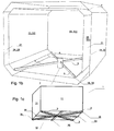
- a cylindrical tank is shown illustrated i fig. 1a
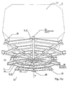
- other geometries should be considered as being within the scope of the invention, such as any kind of prismatic geometry in particular being of rectangular shape as illustrated in Fig. 1 b and 1c, and in Fig. 11c .
- the choice of geometry is a design issue which although central to the design of the ship itself is not central to the present invention.
- One may for instance envisage a spherical tank wherein a bottom portion of the tank wall structure has been removed, and replaced by a mainly planar tank bottom structure thus being furnished.
- this tank bottom structure (10) may be arranged a central hub (2) and possibly the radially arranged beams (3) according to an embodiment of the invention.
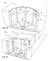
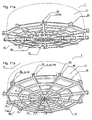
- a cryogenic tank (1) arranged within a marine vessel are shown in Fig. 2a and in Figs. 7a and b, and in Figs. 11a, b, and c .
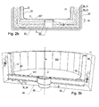
- Fig 2a further illustrates some of the details shown in Fig 1 , such as the ship's tank hub retainer (20) on the structural tank support floor (23) of a tank slot in the ship.
- FIG. 3a and 3b illustrate further details such as bottom insulation (8), cylinder wall insulation (18) and a vertical tank axis (9).
- the structural tank support structure (23) serves a variety of purposes, however one of the major advantages of using this system is that the tank may be prefabricated on shore, and simply being hoisted and lowered into the upon ship's tank slot onto the hub retainer (20) in one simple operation. This may significantly ease the installation of cryogenic tanks in ships. This is a significant advantage as many FPSU and FSRU vessels are modified surface vessels. Thus the modification of the ship and the construction of the cryogenic tanks may take place concurrently instead of sequentially. In the same manner, if there should be need for removal of the tanks for maintenance, a cryogenic tank may simply be hoisted out of the vessel. This contrasts greatly to the costly and difficult maintenance of LNG tanks as known in the background art.
- a significant advantage of the internal beam structure in the tank bottom structure as illustrated in Fig. 1b is the fact that the bottom liner plate resides lower, thus the tank volume is increased while the centre of gravity of the tank may be lowered, providing both economic and stability advantages;
- Lateral forces between the ship and the liquefied gas are, by virtue of the invention, transferred radially through the central hub (2), through the entire bottom structure (10), as compressional and / or tensional forces through the tank bottom structure (10), and further transferred as, shear forces from the tank bottom structure (10) into the tank wall structure (11) which is erected about a circumference of the bottom plate structure (10).
- the force transfer for a tank structure according to the invention better distributes throughout the tank structure and thus prevents crack formation, particularly in the lower peripheral transition between the tank bottom liner plate (113) and the tank wall liner plate (111).
- strains due particularly to rolling, pitching and resulting sloshing may be reduced in a tank according to the invention as compared to the prior art.
- the tank bottom structure (10) comprises at least three, preferably four or more radial beams (3) attached with their radially inner ends to said central hub (2).
- the radial beams (3) shall in a preferred embodiment of the invention support vertical girders (12) extending from near the outer ends of said radial beams (3).
- Non-permeable liner plates (131, 111) preferably form the impermeable tank liner of the tank bottom and tank wall structures (10, 11). The liner plates are attached to the beam and girder (3, 12) structures.
- the tank wall structure (11, 12) may be reinforced in the circumferential direction by rods, bands or wires, or may be provided with hoop windings of wire or glass fibre, aramid fibre, carbon fibre or the like, and the tank may be provided with a top with a circumference corresponding to the bottom circumference.
- the top of the tank according to the invention would not require any lateral retainer because all translational and rotational action-reaction force transfers occurs through the bottom plate structure.
- the central hub (2) is essentially not arranged for retaining the tank (1) from moving in the vertical axial direction. Although such a vertical retaining function via the central hub (2) is imaginable, such as illustrated in Fig. 8 , such a retaining function would be indirect with respect to the tank wall structure (11), and would involve transfer of vertical forces from the tank wall structure (11) through undesired vertical shear forces in the beams (3) of the bottom plate structure (11).
- the central tank hub (2) and its corresponding tank hub retainer (20) preferably handle only forces in a horizontal plane in the ship's neutral position.
- transfer of upwardly directed forces on the tank wall structure (11, 12) relative to the ship's tank recess bottom (23) is conducted through vertical force retainers (4) arranged between the tank support recess bottom support structure (23) and the circumference (15) of the tank bottom structure, preferably the outer portions (35) of the beams (3) of the tank bottom structure (10).
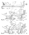
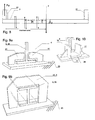
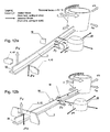
- the vertical force retainers (4) comprise a base plate welded or otherwise attached to the substructure (23), with standing support plates welded onto the base plate, said standing support plates provided with arms (41) for embracing the lower lateral flanges of the flat lying H-beam cross-section of said radial beams (3).
- This is illustrated in Figs. 5a , 9a , 11a and c, 12a and 14a .
- the plates with the arms (41) may be welded in place after the tank has been lowered into its correct position on the hub retainer (20) in the compartment.
- H-beams have been shown, any suitable beam structure may be used as is evident.
- the vertical force retainers (4) comprise a base plate welded or otherwise attached to the substructure (23), with standing support plates welded onto the base plate, said standing support plates comprising inverted "U"-shape bridles or arcs (42) for embracing the outer portions (35) of the horizontal radial beams (3). This is illustrated in Figs. 5b , 9b , 11b , 12b and 14b .
- the inverted "U"-shaped vertical retainer plates (42) may also be welded in place after the tank has been lowered into its correct position on the hub retainer (20) in the compartment.
- Figs. 5a and 5b illustrate that vertically directed lifting forces arising in the tank wall structure (11, 12) will be counteracted by the vertical force retainers (4) arranged directly below the tank wall structure (11) and guided into the supporting substructure (23) of the ship.
- the vertical force retainers (4) arranged directly below the tank wall structure (11) and guided into the supporting substructure (23) of the ship.
- sloshing forces and roll forces and roll accelerations which may be severe in high sea states or due to listing incurred from displaced load or due to an accident, such forces may be counteracted at least up to a pre-defined static angle and for a full tank, for e.g. a heel of up to 30 degrees to the port or starboard side.
- the tank according to the invention may simplistically be described as being kept in place laterally through the use of a central hub in the bottom plate structure, and prevented from leaving the substructure or even toppling by, means of vertical force retainers holding down the lower rim of the cylindrical tank wall towards the underlying tank support structure, as shown in figure 4 .
- This will prevent damage to the tank due to roll, pitch, surge and gear movements of the ship, including action and reaction forces due to collision and grounding.
- Figs. 9a and 9b will allow beam longitudinal motion due to radial thermal contraction of the beams (3) and may also be used for preventing undesired relative rotational movement of the tank bottom structure (10) relative to the underlying supporting substructure (23).
- Such rotational accelerations may arise both due to the ship's turning and also due to waves giving rise to yaw, i.e. a rotation of the ship about a vertical axis.
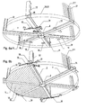
- Such rotational movements of the tank (1) relative to the ship may be counteracted through the application of anti-rotational retainers (16), please see Figs. 6a and 6b , Fig. 10 , (and Figs 11a, b, and c ).
- the various forces acting upon a marine vessel are shown in Fig 13 .
- the counteracting forces as well as the principle of how the tank functions is shown in Figs. 12a and 12b .
- the anti-rotational retainers (16) comprise vertically arranged lateral retainer surface plates (17) extending parallel to the radial beams (3), said surface plates for resting against lateral surfaces of the radial beams (3), and having a bottom slide support (28) for vertically supporting the beam's (3) lower flange (14), which slide support (28) should further have thermal insulation properties.
- An advantage of the embodiment illustrated in Fig. 6a is that the anti-rotational retainers (16) are separate from the tank hub (2) and their roles are separate: the tank hub (2) to prevent any translational movement between the tank (1) and the hub retainer (20) on the structural tank support floor (23) of the ship, the anti-rotational retainers (16) are from preventing the tank to rotate relative to the ship.
- Such rotational forces may be induced by turning the ship, by intermittently turning the ship through yaw movements induced by sea waves, or through sloshing.
- the position of anti-rotational retainers (16) as shown in Fig. 6a may be moved to beyond the lower rim (15) of the tank bottom plate (13).
- the beam structure is internal, and thus the bottom plate may be arranged welded-in attached to the lower portions of the horizontal beams (3), thus leaving only the tank hub (2) forming a notch in the bottom plate.
- the anti-rotational retainers (16) arranged as in Fig. 6b provide two additional advantages: Firstly, they are arranged at a maximum radius of the tank, thus they provide the maximum anti-rotational moment available, and need not be designed as rigid as the ones illustrated in Fig.
- the arrangement of the anti-rotational retainers (16) positioned in a radial distance (Rmaj) beyond the tank wall (11) and the tank bottom (13) may provide a lower arranged tank bottom plate structure and thus a larger volume of the tank and a lowered gravity mass, and a better anti-rotational force moment than anti-rotational retainers arranged further in toward the central hub (2), and it also provides fewer structural penetrations of the insulation layer below the tank bottom.
- the anti-rotational retainers (16) will constitute radially opposite pairs as shown in Fig. 6b , so no moment will be induced in the tank hub (2, 20).
- the inverted "U"-shape vertical retainers of Fig. 11b further provide lowering of the tank bottom liner plate (113) so as to render an internal structure bottom plate structure (10) and thus increasing the tank volume in the same manner as above.
- Fig. 8 illustrates why there is a need for arranging the vertical retainers near the outer periphery of the tank such that the moment arm between vertical forces from the tank wall and retention vertical forces acting on the bottom structure become short. If the moment arm acting via the tank walls onto the tank bottom structure is undesiredly large, such as illustrated, there might occur failures in the tank bottom structure due to shear forces, with crack formation and possible leakage as result.
- the above described tank according to the invention should have marine operational advantages. Thermal transfer may be kept low due to the fact that any support blocks or retainers are only required about the bottom plate of the tank, and no structural parts need cross the insulation layer in levels above the bottom plate of the tank, thus the insulation layer around the entire wall structure (11) may be continuous. This also simplifies the structural design of the cryogenic tank.
- a tank (1) according to the invention may be lowered into the recess, the central hub (2) for entering onto the hub retainer (20).
- the vertical force retainers (4) and possible anti-rotational retainers (16) may be prepared for receiving the radial beams (3) and may be completed by welding the arms (41) or inverted "U"-shaped bridles for embracing the the radial beams (3).
- the bottom plate structure (10) and the beams (3) may be encompassed by a radially oriented rail (19) for being engaged by the vertical retainers (4).
- Such an arrangement may allow rotational relative movement of the cryogenic.tank, a possible configuration being illustrated in fig. 4 .
- vertical retainers (4) may be arranged in the form of wedges (43) (illustrated in Fig. 4 ) arranged in the wall (24) of the tank compartment (25), the wedges (43) for being pivoted in and out of the compartment wall (24) for blocking the outer ends (35) of the beams (3) of the tank bottom structure (10) when the tank (1) is in place.
- wedges (43) may be controlled from the external space around the tank compartment (25), thus facilitating installation and removal of the tank in the ship. This may further reduce the requirements for space around the tank wall structure (11) and the periphery of the tank bottom structure (10) and improve the available tank volume of an internal structure tank to be lowered into a tank slot in a ship.
- An advantage of the present invention is that the tank's central hub (2) is of small extent compared to the extent of the tank bottom structure (10). Thus the total thermal contraction or expansion of the central hub (2) will be relatively negligible during cooling or heating, compared to the extensive contraction or expansion incurred for the entire tank bottom structure compared to the compartment bottom when the tank is cooled or heated.
- the small extent of the tank hub (2) will allow that the tank hub may be retained in the single-point retainer (20) also when heated, which will allow the ship to sail with an empty tank, an operation which would not be possible with a cryogenic tank according to DE1781041 .
- the tank according to the invention thus solves some of the problems related to thermal contraction, lateral retaining, longitudinal retaining, sloshing load forces, distribution of rolling-induced forces, and stability of cryogenic tanks.
- an internal tower is arranged in a cryogenic tank, the tower holding vertical pipes for filling and draining LNG or other fluids to and from the tank through the use of internal pumps and valves.
- Such other fluids may be Nitrogen, Carbon dioxide, LPG, and gas condensates.
- the bottom hub (2) and hub retainer (20) themselves may provide passages for an inlet and / or an outlet for cryogenic fluid, thus providing an easy manner by which the tank may be filled or emptied.
- Figs. 14a and 14b illustrate in a bottom view and an enlarged elevation view of embodiments of the invention showing enlarged peripheral vertical supports (4) arranged along the circumference of the tank for embracing the lower flanges of radial beams (3), which may render the previously described anti-rotational retainers (16) redundant as such.
- Such arrangements will be easier to manufacture, inspect, and install, and may allow a flat bottom of the tank compartment.
- Fig. 15a illustrates a simplified vertical section through a tank bottom structure according to a preferred embodiment of the invention with a central hub (20) of a female type welded in between inner ends of radial beams (3), the central hub entered onto a male type central hub retainer (20) fixed in the framework of a supporting beam substructure (23) for holding the tank (1).
- An advantage of the female-type central hub (2) of Fig. 15a is that less bending moments are induced in the tank bottom structure (10) than for the alternative male-type central hub (2') illustrated in fig. 15b below.
- Fig. 15b illustrates a simplified vertical section through a tank bottom structure of an alternative embodiment of the invention, with a central hub (2') of a male type welded in between inner ends of radial beams (3), the central hub (2') entered into a central hub retainer (20') of the female type which is fixed in the framework of a supporting beam substructure (23) for holding the tank (1).
Landscapes
- Engineering & Computer Science (AREA)
- Mechanical Engineering (AREA)
- General Engineering & Computer Science (AREA)
- Filling Or Discharging Of Gas Storage Vessels (AREA)
Claims (21)
- Ein System, umfassend einen Behälter (1) für verflüssigtes Gas mit einer Behälterbodenstruktur (10) und einem Behälterträgerstrukturboden (23), wobei die Behälterbodenstruktur eine Behälterwandstruktur (11) trägt,
gekennzeichnet durch
eine mittlere Nabe (2) in der Behälterbodenstruktur (10), wobei die mittlere Nabe (2) von einer entsprechenden Nabenhalterung (20) an dem Behälterträgerstrukturboden (23) gehalten wird, wobei die Nabenhalterung (20) allgemein im Wesentlichen sämtliche radial gerichteten Haltekräfte auf die mittlere Nabe (2) in der Ebene der Behälterbodenstruktur (10) liefert. - Das System nach Anspruch 1, wobei die mittlere Nabe (2) an radiale Strukturträger (3) gekoppelt ist, die ferner zum Tragen der Behälterwandstruktur (11) angeordnet sind.
- Das System nach Anspruch 2, wobei die radialen Träger (3) an einer vertikalen Bewegung durch vertikale Halterungen (4) gehindert werden.
- Das System nach Anspruch 2, wobei die Behälterwandstruktur (11) Balken (12) umfasst, die sich von nahen äußeren Enden der radialen Träger (3) erstrecken, wobei die Balken (12) im Allgemeinen parallel zu einer vertikalen Behälterachse (9) ausgerichtet sind.
- Das System nach Anspruch 4, wobei die Träger (3) eine Behälterbodenauskleidung (131) tragen.
- Das System nach Anspruch 1, wobei sich die Behälterwandstruktur (11) von und um einen Umfang (15) der Behälterbodenstruktur (10) erstreckt, wobei die Behälterwandstruktur (11) derart angeordnet ist, dass sie vom Abheben durch eine Roll- und/oder Kippbewegung weg von dem Behälterträgerstrukturboden (23) durch vertikale Richtungshalterungen (4) gehalten wird, die an dem Behälterträgerstrukturboden (23) angeordnet sind.
- Das System nach Anspruch 3, wobei die vertikalen Halterungen (4) ferner angeordnet sind, um eine Drehbewegung des Behälters (1) um die mittlere Nabe (2) zu verhindern.
- Das System nach Anspruch 1, wobei der Kryogenbehälter (1) in einem Behälterkompartment (25) mit einer Schicht aus Isoliermaterial (8, 18) eingeschlossen ist, die zwischen der Behälterbodenstruktur (10) und dem ersten Kompartmentboden (23) angeordnet ist und zwischen der Behälterwandstruktur (11) und der Kompartmentwand (24) angeordnet ist.
- Das System nach Anspruch 1, wobei der Behälterträgerstrukturboden (23) sich in einem Behälterkompartment (25) befindet.
- Das System nach Anspruch 1, wobei der Behälterträgerstrukturboden (23) in einem Wasserfahrzeug (30) angeordnet ist.
- Das System nach Anspruch 10, wobei der Behälterträgerstrukturboden (23) ein Deck des Wasserfahrzeugs (30) ist.
- Das System nach Anspruch 10 oder 11, wobei die Nabenhalterung (20) an einem horizontal ausgerichteten Schiffsbehälterträgerstrukturboden (23) befestigt ist.
- Das System nach Anspruch 1, wobei die Behälterwandstruktur (11) zylindrisch ist, wobei die Behälterbodenstruktur (10) allgemein eine kreisförmige Ebene bildet.
- Das System nach Anspruch 1, wobei der Behälter (1) prismenförmig ist.
- Das System nach Anspruch 1, wobei der Kryogenbehälter angeordnet ist, um LNG, LPG oder ein beliebiges Fluid mit einer niedrigen Temperatur zu beinhalten.
- Das System nach Anspruch 1, wobei die Behälterbodenstruktur (10) mit einer Bodenauskleidungsplatte (131) vorgesehen ist und die Behälterwandstruktur (11) mit einer Wandauskleidungsplatte (111) vorgesehen ist.
- Das System nach Anspruch 1, das in einem Wasserfahrzeug zur Herstellung und Aufbewahrung von LNG angeordnet ist.
- Das System nach Anspruch 1, das in einem Wasserfahrzeug zur Aufbewahrung und Regasifizierung von LNG angeordnet ist.
- Das System nach Anspruch 1, das in einem Schiff zum Transport von LNG angeordnet ist.
- Das System nach Anspruch 1, wobei die Behälterbodennabe (20) mit einem oder mehreren Kanälen zum Befüllen oder Entleeren des Behälters mit einem kryogenen Fluid angeordnet ist.
- Ein Verfahren zur Installation eines Systems nach Anspruch 1, das im Anheben des Behälters (1) und Absenken des Behälters (1) direkt auf die Bodennabenhalterung (20) besteht.
Applications Claiming Priority (3)
| Application Number | Priority Date | Filing Date | Title |
|---|---|---|---|
| US99672207P | 2007-12-03 | 2007-12-03 | |
| NO20076213A NO332554B1 (no) | 2007-12-03 | 2007-12-03 | En tank for likvidisert gass med et sentralt nav i bunnstrukturen. |
| PCT/NO2008/000431 WO2009072897A1 (en) | 2007-12-03 | 2008-12-03 | A liquefied gas tank with a central hub in the bottom structure |
Publications (2)
| Publication Number | Publication Date |
|---|---|
| EP2247888A1 EP2247888A1 (de) | 2010-11-10 |
| EP2247888B1 true EP2247888B1 (de) | 2011-09-28 |
Family
ID=40436445
Family Applications (1)
| Application Number | Title | Priority Date | Filing Date |
|---|---|---|---|
| EP08855814A Not-in-force EP2247888B1 (de) | 2007-12-03 | 2008-12-03 | Flüssiggastank mit mittlerer nabe in der bodenstruktur |
Country Status (10)
| Country | Link |
|---|---|
| EP (1) | EP2247888B1 (de) |
| JP (1) | JP5232242B2 (de) |
| KR (1) | KR20100102139A (de) |
| CN (1) | CN101932867B (de) |
| AT (1) | ATE526536T1 (de) |
| BR (1) | BRPI0819987A2 (de) |
| MY (1) | MY149742A (de) |
| NO (1) | NO332554B1 (de) |
| RU (1) | RU2478868C2 (de) |
| WO (1) | WO2009072897A1 (de) |
Cited By (1)
| Publication number | Priority date | Publication date | Assignee | Title |
|---|---|---|---|---|
| WO2022221924A1 (en) * | 2021-04-22 | 2022-10-27 | Christopher Colin Stephen | Gas transportation and storage system |
Families Citing this family (7)
| Publication number | Priority date | Publication date | Assignee | Title |
|---|---|---|---|---|
| JP2012500371A (ja) * | 2008-08-21 | 2012-01-05 | テーゲーエー、マリン、ガス、エンジニヤリング、ゲーエムベーハー | 低温媒体用タンクを支持するための装置 |
| PL2981756T3 (pl) | 2013-04-05 | 2022-07-18 | Cryoshelter Gmbh | Pojemnik z pojemnikiem zewnętrznym i pojemnikiem wewnętrznym oraz z urządzeniem do zawieszania |
| KR101643092B1 (ko) * | 2015-04-15 | 2016-07-26 | 한국과학기술연구원 | 저열손실 저온 유체 용기 |
| DE102015113908B4 (de) | 2015-08-21 | 2023-05-04 | Truma Gerätetechnik GmbH & Co. KG | Füllstandsmessgerät |
| KR102211324B1 (ko) * | 2019-04-16 | 2021-02-04 | 한국가스공사 | 내조의 인양이 가능한 액화 가스 탱크 및 액화 가스 탱크에서 내조의 인양 방법 |
| RU2771516C1 (ru) * | 2021-04-12 | 2022-05-05 | Трума Герететехник Гмбх Унд Ко. Кг | Конструктивный узел, состоящий из измерителя уровня заполнения и дистанционного элемента |
| CN115290403A (zh) * | 2022-08-05 | 2022-11-04 | 华能核能技术研究院有限公司 | 放射性惰性气体压缩取样瓶及含有该取样瓶的检测装置 |
Family Cites Families (16)
| Publication number | Priority date | Publication date | Assignee | Title |
|---|---|---|---|---|
| DE1034499B (de) * | 1956-03-12 | 1958-07-17 | Iaweseria Ag | Frachtschiff fuer fluessige Gase |
| US3094963A (en) * | 1957-04-05 | 1963-06-25 | Wm Cory & Son Ltd | Marine tankers |
| US3007598A (en) * | 1958-06-24 | 1961-11-07 | Conch Int Methane Ltd | Tank construction |
| US3072088A (en) * | 1960-05-24 | 1963-01-08 | Conch Int Methane Ltd | Cold cargo transportation means |
| US3064612A (en) * | 1960-10-20 | 1962-11-20 | Maryland Shipbuilding And Dryd | Carrier constructions for bulk fluids |
| NL271878A (de) * | 1961-02-07 | |||
| DE1199650B (de) * | 1961-04-11 | 1965-08-26 | Willy H Schlieker K G | Schiff zum Transport von Fluessiggasen |
| DE1256236B (de) * | 1963-02-14 | 1967-12-14 | Mcmullen John J | Waermeisolierter doppelwandiger Tank zur Lagerung oder zum Transport tiefsiedender verfluessigter Gase |
| DE1501699A1 (de) * | 1966-11-26 | 1969-12-18 | Wesen Ag | Behaelter zur Aufnahme tiefgekuehlter Fluessigkeiten |
| DE1781041A1 (de) * | 1968-08-14 | 1970-10-22 | Linde Ag | Tankschiff zum Transport von Fluessiggasen |
| JPS5018206B1 (de) * | 1970-05-15 | 1975-06-27 | ||
| SU1346901A1 (ru) * | 1986-04-21 | 1987-10-23 | Особое конструкторско-технологическое бюро Физико-технического института низких температур АН УССР | Криогенный резервуар дл хранени и транспортировки сжиженных газов |
| US5727492A (en) * | 1996-09-16 | 1998-03-17 | Marinex International Inc. | Liquefied natural gas tank and containment system |
| RU9928U1 (ru) * | 1998-02-10 | 1999-05-16 | Научно-производственное общество "Салютхиммаш" | Резервуар для транспортирования и хранения сжиженных газов под давлением |
| CN1100231C (zh) * | 1999-02-24 | 2003-01-29 | 埃克森美孚石油公司 | 液化气储罐 |
| GB0703693D0 (en) * | 2007-02-26 | 2007-04-04 | Jahre Group As | Support structure |
-
2007
- 2007-12-03 NO NO20076213A patent/NO332554B1/no not_active IP Right Cessation
-
2008
- 2008-12-03 EP EP08855814A patent/EP2247888B1/de not_active Not-in-force
- 2008-12-03 MY MYPI2010002561A patent/MY149742A/en unknown
- 2008-12-03 CN CN200880125527.XA patent/CN101932867B/zh not_active Expired - Fee Related
- 2008-12-03 JP JP2010536871A patent/JP5232242B2/ja not_active Expired - Fee Related
- 2008-12-03 KR KR1020107014757A patent/KR20100102139A/ko not_active Abandoned
- 2008-12-03 BR BRPI0819987A patent/BRPI0819987A2/pt not_active IP Right Cessation
- 2008-12-03 WO PCT/NO2008/000431 patent/WO2009072897A1/en not_active Ceased
- 2008-12-03 AT AT08855814T patent/ATE526536T1/de not_active IP Right Cessation
- 2008-12-03 RU RU2010127353/06A patent/RU2478868C2/ru not_active IP Right Cessation
Cited By (1)
| Publication number | Priority date | Publication date | Assignee | Title |
|---|---|---|---|---|
| WO2022221924A1 (en) * | 2021-04-22 | 2022-10-27 | Christopher Colin Stephen | Gas transportation and storage system |
Also Published As
| Publication number | Publication date |
|---|---|
| KR20100102139A (ko) | 2010-09-20 |
| CN101932867B (zh) | 2013-01-16 |
| NO332554B1 (no) | 2012-10-22 |
| BRPI0819987A2 (pt) | 2017-06-13 |
| JP2011506164A (ja) | 2011-03-03 |
| MY149742A (en) | 2013-10-14 |
| NO20076213L (no) | 2009-06-04 |
| EP2247888A1 (de) | 2010-11-10 |
| RU2010127353A (ru) | 2012-01-10 |
| WO2009072897A1 (en) | 2009-06-11 |
| ATE526536T1 (de) | 2011-10-15 |
| RU2478868C2 (ru) | 2013-04-10 |
| CN101932867A (zh) | 2010-12-29 |
| JP5232242B2 (ja) | 2013-07-10 |
Similar Documents
| Publication | Publication Date | Title |
|---|---|---|
| US8091494B2 (en) | Liquefied gas tank with a central hub in the bottom structure | |
| EP2293971B1 (de) | Systeme und verfahren zum stützen von tanks in einem frachtschiff | |
| EP2247888A1 (de) | Flüssiggastank mit mittlerer nabe in der bodenstruktur | |
| EP2583023B1 (de) | Stütze für tanks in schiffen | |
| US11821587B2 (en) | Sealed and thermally insulating tank | |
| US12365423B2 (en) | Apparatus for gas storage and transport | |
| KR20090010775U (ko) | 슬로싱 저감수단을 가지는 멤브레인 타입 lng 저장탱크및 상기 lng 저장탱크를 가지는 부유식 해상 구조물 | |
| AU2008332002B2 (en) | A liquefied gas tank with a central hub in the bottom structure | |
| KR102396652B1 (ko) | 액화가스 저장탱크 및 이를 포함하는 선박 | |
| KR102327624B1 (ko) | 액화가스 저장탱크 및 이를 포함하는 선박 | |
| KR102742797B1 (ko) | 액화 가스를 위한 저장 시설 | |
| KR102327627B1 (ko) | 액화가스 저장탱크 및 이를 포함하는 선박 | |
| KR102327631B1 (ko) | 액화가스 저장탱크 및 이를 포함하는 선박 | |
| KR200482843Y1 (ko) | 독립형 탱크의 지지 구조물 | |
| KR102581639B1 (ko) | 발판 구조물의 레그 지지장치 및 이를 이용한 발판 구조물의 지지방법 | |
| KR102396651B1 (ko) | 액화가스 저장탱크 및 이를 포함하는 선박 | |
| KR102348833B1 (ko) | 액화가스 저장탱크 및 이를 포함하는 선박 | |
| US12578061B2 (en) | Sealed and thermally insulating tank | |
| KR102327630B1 (ko) | 액화가스 저장탱크 및 이를 포함하는 선박 | |
| KR20220010382A (ko) | 액화가스 저장탱크 및 이를 포함하는 선박 | |
| KR102963386B1 (ko) | 유체-밀봉 및 단열 탱크를 위한 탱크 벽 |
Legal Events
| Date | Code | Title | Description |
|---|---|---|---|
| PUAI | Public reference made under article 153(3) epc to a published international application that has entered the european phase |
Free format text: ORIGINAL CODE: 0009012 |
|
| 17P | Request for examination filed |
Effective date: 20100701 |
|
| AK | Designated contracting states |
Kind code of ref document: A1 Designated state(s): AT BE BG CH CY CZ DE DK EE ES FI FR GB GR HR HU IE IS IT LI LT LU LV MC MT NL NO PL PT RO SE SI SK TR |
|
| AX | Request for extension of the european patent |
Extension state: AL BA MK RS |
|
| DAX | Request for extension of the european patent (deleted) | ||
| GRAP | Despatch of communication of intention to grant a patent |
Free format text: ORIGINAL CODE: EPIDOSNIGR1 |
|
| GRAS | Grant fee paid |
Free format text: ORIGINAL CODE: EPIDOSNIGR3 |
|
| GRAA | (expected) grant |
Free format text: ORIGINAL CODE: 0009210 |
|
| AK | Designated contracting states |
Kind code of ref document: B1 Designated state(s): AT BE BG CH CY CZ DE DK EE ES FI FR GB GR HR HU IE IS IT LI LT LU LV MC MT NL NO PL PT RO SE SI SK TR |
|
| REG | Reference to a national code |
Ref country code: GB Ref legal event code: FG4D |
|
| REG | Reference to a national code |
Ref country code: CH Ref legal event code: EP |
|
| REG | Reference to a national code |
Ref country code: IE Ref legal event code: FG4D |
|
| REG | Reference to a national code |
Ref country code: DE Ref legal event code: R096 Ref document number: 602008010178 Country of ref document: DE Effective date: 20111201 |
|
| REG | Reference to a national code |
Ref country code: NL Ref legal event code: T3 |
|
| PG25 | Lapsed in a contracting state [announced via postgrant information from national office to epo] |
Ref country code: LT Free format text: LAPSE BECAUSE OF FAILURE TO SUBMIT A TRANSLATION OF THE DESCRIPTION OR TO PAY THE FEE WITHIN THE PRESCRIBED TIME-LIMIT Effective date: 20110928 Ref country code: HR Free format text: LAPSE BECAUSE OF FAILURE TO SUBMIT A TRANSLATION OF THE DESCRIPTION OR TO PAY THE FEE WITHIN THE PRESCRIBED TIME-LIMIT Effective date: 20110928 Ref country code: SE Free format text: LAPSE BECAUSE OF FAILURE TO SUBMIT A TRANSLATION OF THE DESCRIPTION OR TO PAY THE FEE WITHIN THE PRESCRIBED TIME-LIMIT Effective date: 20110928 Ref country code: FI Free format text: LAPSE BECAUSE OF FAILURE TO SUBMIT A TRANSLATION OF THE DESCRIPTION OR TO PAY THE FEE WITHIN THE PRESCRIBED TIME-LIMIT Effective date: 20110928 |
|
| REG | Reference to a national code |
Ref country code: NO Ref legal event code: T2 Effective date: 20110928 |
|
| LTIE | Lt: invalidation of european patent or patent extension |
Effective date: 20110928 |
|
| PG25 | Lapsed in a contracting state [announced via postgrant information from national office to epo] |
Ref country code: AT Free format text: LAPSE BECAUSE OF FAILURE TO SUBMIT A TRANSLATION OF THE DESCRIPTION OR TO PAY THE FEE WITHIN THE PRESCRIBED TIME-LIMIT Effective date: 20110928 Ref country code: SI Free format text: LAPSE BECAUSE OF FAILURE TO SUBMIT A TRANSLATION OF THE DESCRIPTION OR TO PAY THE FEE WITHIN THE PRESCRIBED TIME-LIMIT Effective date: 20110928 Ref country code: GR Free format text: LAPSE BECAUSE OF FAILURE TO SUBMIT A TRANSLATION OF THE DESCRIPTION OR TO PAY THE FEE WITHIN THE PRESCRIBED TIME-LIMIT Effective date: 20111229 Ref country code: LV Free format text: LAPSE BECAUSE OF FAILURE TO SUBMIT A TRANSLATION OF THE DESCRIPTION OR TO PAY THE FEE WITHIN THE PRESCRIBED TIME-LIMIT Effective date: 20110928 Ref country code: CY Free format text: LAPSE BECAUSE OF FAILURE TO SUBMIT A TRANSLATION OF THE DESCRIPTION OR TO PAY THE FEE WITHIN THE PRESCRIBED TIME-LIMIT Effective date: 20110928 |
|
| REG | Reference to a national code |
Ref country code: AT Ref legal event code: MK05 Ref document number: 526536 Country of ref document: AT Kind code of ref document: T Effective date: 20110928 |
|
| PG25 | Lapsed in a contracting state [announced via postgrant information from national office to epo] |
Ref country code: BE Free format text: LAPSE BECAUSE OF FAILURE TO SUBMIT A TRANSLATION OF THE DESCRIPTION OR TO PAY THE FEE WITHIN THE PRESCRIBED TIME-LIMIT Effective date: 20110928 |
|
| PG25 | Lapsed in a contracting state [announced via postgrant information from national office to epo] |
Ref country code: IS Free format text: LAPSE BECAUSE OF FAILURE TO SUBMIT A TRANSLATION OF THE DESCRIPTION OR TO PAY THE FEE WITHIN THE PRESCRIBED TIME-LIMIT Effective date: 20120128 Ref country code: CZ Free format text: LAPSE BECAUSE OF FAILURE TO SUBMIT A TRANSLATION OF THE DESCRIPTION OR TO PAY THE FEE WITHIN THE PRESCRIBED TIME-LIMIT Effective date: 20110928 Ref country code: SK Free format text: LAPSE BECAUSE OF FAILURE TO SUBMIT A TRANSLATION OF THE DESCRIPTION OR TO PAY THE FEE WITHIN THE PRESCRIBED TIME-LIMIT Effective date: 20110928 |
|
| PG25 | Lapsed in a contracting state [announced via postgrant information from national office to epo] |
Ref country code: RO Free format text: LAPSE BECAUSE OF FAILURE TO SUBMIT A TRANSLATION OF THE DESCRIPTION OR TO PAY THE FEE WITHIN THE PRESCRIBED TIME-LIMIT Effective date: 20110928 Ref country code: PT Free format text: LAPSE BECAUSE OF FAILURE TO SUBMIT A TRANSLATION OF THE DESCRIPTION OR TO PAY THE FEE WITHIN THE PRESCRIBED TIME-LIMIT Effective date: 20120130 Ref country code: IT Free format text: LAPSE BECAUSE OF FAILURE TO SUBMIT A TRANSLATION OF THE DESCRIPTION OR TO PAY THE FEE WITHIN THE PRESCRIBED TIME-LIMIT Effective date: 20110928 Ref country code: EE Free format text: LAPSE BECAUSE OF FAILURE TO SUBMIT A TRANSLATION OF THE DESCRIPTION OR TO PAY THE FEE WITHIN THE PRESCRIBED TIME-LIMIT Effective date: 20110928 |
|
| PG25 | Lapsed in a contracting state [announced via postgrant information from national office to epo] |
Ref country code: MC Free format text: LAPSE BECAUSE OF NON-PAYMENT OF DUE FEES Effective date: 20111231 Ref country code: DK Free format text: LAPSE BECAUSE OF FAILURE TO SUBMIT A TRANSLATION OF THE DESCRIPTION OR TO PAY THE FEE WITHIN THE PRESCRIBED TIME-LIMIT Effective date: 20110928 |
|
| PLBE | No opposition filed within time limit |
Free format text: ORIGINAL CODE: 0009261 |
|
| STAA | Information on the status of an ep patent application or granted ep patent |
Free format text: STATUS: NO OPPOSITION FILED WITHIN TIME LIMIT |
|
| PG25 | Lapsed in a contracting state [announced via postgrant information from national office to epo] |
Ref country code: PL Free format text: LAPSE BECAUSE OF FAILURE TO SUBMIT A TRANSLATION OF THE DESCRIPTION OR TO PAY THE FEE WITHIN THE PRESCRIBED TIME-LIMIT Effective date: 20110928 |
|
| 26N | No opposition filed |
Effective date: 20120629 |
|
| REG | Reference to a national code |
Ref country code: IE Ref legal event code: MM4A |
|
| REG | Reference to a national code |
Ref country code: DE Ref legal event code: R097 Ref document number: 602008010178 Country of ref document: DE Effective date: 20120629 |
|
| PG25 | Lapsed in a contracting state [announced via postgrant information from national office to epo] |
Ref country code: IE Free format text: LAPSE BECAUSE OF NON-PAYMENT OF DUE FEES Effective date: 20111203 |
|
| PG25 | Lapsed in a contracting state [announced via postgrant information from national office to epo] |
Ref country code: MT Free format text: LAPSE BECAUSE OF FAILURE TO SUBMIT A TRANSLATION OF THE DESCRIPTION OR TO PAY THE FEE WITHIN THE PRESCRIBED TIME-LIMIT Effective date: 20110928 |
|
| PG25 | Lapsed in a contracting state [announced via postgrant information from national office to epo] |
Ref country code: ES Free format text: LAPSE BECAUSE OF FAILURE TO SUBMIT A TRANSLATION OF THE DESCRIPTION OR TO PAY THE FEE WITHIN THE PRESCRIBED TIME-LIMIT Effective date: 20120108 |
|
| PG25 | Lapsed in a contracting state [announced via postgrant information from national office to epo] |
Ref country code: LU Free format text: LAPSE BECAUSE OF NON-PAYMENT OF DUE FEES Effective date: 20111203 |
|
| PG25 | Lapsed in a contracting state [announced via postgrant information from national office to epo] |
Ref country code: BG Free format text: LAPSE BECAUSE OF FAILURE TO SUBMIT A TRANSLATION OF THE DESCRIPTION OR TO PAY THE FEE WITHIN THE PRESCRIBED TIME-LIMIT Effective date: 20111228 |
|
| REG | Reference to a national code |
Ref country code: CH Ref legal event code: PL |
|
| PG25 | Lapsed in a contracting state [announced via postgrant information from national office to epo] |
Ref country code: TR Free format text: LAPSE BECAUSE OF FAILURE TO SUBMIT A TRANSLATION OF THE DESCRIPTION OR TO PAY THE FEE WITHIN THE PRESCRIBED TIME-LIMIT Effective date: 20110928 |
|
| PG25 | Lapsed in a contracting state [announced via postgrant information from national office to epo] |
Ref country code: CH Free format text: LAPSE BECAUSE OF NON-PAYMENT OF DUE FEES Effective date: 20121231 Ref country code: HU Free format text: LAPSE BECAUSE OF FAILURE TO SUBMIT A TRANSLATION OF THE DESCRIPTION OR TO PAY THE FEE WITHIN THE PRESCRIBED TIME-LIMIT Effective date: 20110928 Ref country code: LI Free format text: LAPSE BECAUSE OF NON-PAYMENT OF DUE FEES Effective date: 20121231 |
|
| PGFP | Annual fee paid to national office [announced via postgrant information from national office to epo] |
Ref country code: DE Payment date: 20141211 Year of fee payment: 7 Ref country code: NO Payment date: 20141009 Year of fee payment: 7 Ref country code: GB Payment date: 20141219 Year of fee payment: 7 |
|
| PGFP | Annual fee paid to national office [announced via postgrant information from national office to epo] |
Ref country code: FR Payment date: 20141208 Year of fee payment: 7 |
|
| PGFP | Annual fee paid to national office [announced via postgrant information from national office to epo] |
Ref country code: NL Payment date: 20141231 Year of fee payment: 7 |
|
| REG | Reference to a national code |
Ref country code: DE Ref legal event code: R119 Ref document number: 602008010178 Country of ref document: DE |
|
| REG | Reference to a national code |
Ref country code: NO Ref legal event code: MMEP |
|
| GBPC | Gb: european patent ceased through non-payment of renewal fee |
Effective date: 20151203 |
|
| REG | Reference to a national code |
Ref country code: NL Ref legal event code: MM Effective date: 20160101 |
|
| REG | Reference to a national code |
Ref country code: FR Ref legal event code: ST Effective date: 20160831 |
|
| PG25 | Lapsed in a contracting state [announced via postgrant information from national office to epo] |
Ref country code: NL Free format text: LAPSE BECAUSE OF NON-PAYMENT OF DUE FEES Effective date: 20160101 Ref country code: DE Free format text: LAPSE BECAUSE OF NON-PAYMENT OF DUE FEES Effective date: 20160701 Ref country code: NO Free format text: LAPSE BECAUSE OF NON-PAYMENT OF DUE FEES Effective date: 20151231 Ref country code: GB Free format text: LAPSE BECAUSE OF NON-PAYMENT OF DUE FEES Effective date: 20151203 |
|
| PG25 | Lapsed in a contracting state [announced via postgrant information from national office to epo] |
Ref country code: FR Free format text: LAPSE BECAUSE OF NON-PAYMENT OF DUE FEES Effective date: 20151231 |