EP2248588A1 - Système microfluidique pouvant être monté et démonté et procédé de noyage du système - Google Patents
Système microfluidique pouvant être monté et démonté et procédé de noyage du système Download PDFInfo
- Publication number
- EP2248588A1 EP2248588A1 EP20100162009 EP10162009A EP2248588A1 EP 2248588 A1 EP2248588 A1 EP 2248588A1 EP 20100162009 EP20100162009 EP 20100162009 EP 10162009 A EP10162009 A EP 10162009A EP 2248588 A1 EP2248588 A1 EP 2248588A1
- Authority
- EP
- European Patent Office
- Prior art keywords
- microfluidic system
- base plate
- fluid
- cover plate
- plate
- Prior art date
- Legal status (The legal status is an assumption and is not a legal conclusion. Google has not performed a legal analysis and makes no representation as to the accuracy of the status listed.)
- Granted
Links
Images




Classifications
-
- B—PERFORMING OPERATIONS; TRANSPORTING
- B01—PHYSICAL OR CHEMICAL PROCESSES OR APPARATUS IN GENERAL
- B01J—CHEMICAL OR PHYSICAL PROCESSES, e.g. CATALYSIS OR COLLOID CHEMISTRY; THEIR RELEVANT APPARATUS
- B01J19/00—Chemical, physical or physico-chemical processes in general; Their relevant apparatus
- B01J19/0093—Microreactors, e.g. miniaturised or microfabricated reactors
-
- B—PERFORMING OPERATIONS; TRANSPORTING
- B01—PHYSICAL OR CHEMICAL PROCESSES OR APPARATUS IN GENERAL
- B01L—CHEMICAL OR PHYSICAL LABORATORY APPARATUS FOR GENERAL USE
- B01L3/00—Containers or dishes for laboratory use, e.g. laboratory glassware; Droppers
- B01L3/50—Containers for the purpose of retaining a material to be analysed, e.g. test tubes
- B01L3/502—Containers for the purpose of retaining a material to be analysed, e.g. test tubes with fluid transport, e.g. in multi-compartment structures
- B01L3/5027—Containers for the purpose of retaining a material to be analysed, e.g. test tubes with fluid transport, e.g. in multi-compartment structures by integrated microfluidic structures, i.e. dimensions of channels and chambers are such that surface tension forces are important, e.g. lab-on-a-chip
- B01L3/502707—Containers for the purpose of retaining a material to be analysed, e.g. test tubes with fluid transport, e.g. in multi-compartment structures by integrated microfluidic structures, i.e. dimensions of channels and chambers are such that surface tension forces are important, e.g. lab-on-a-chip characterised by the manufacture of the container or its components
-
- B—PERFORMING OPERATIONS; TRANSPORTING
- B01—PHYSICAL OR CHEMICAL PROCESSES OR APPARATUS IN GENERAL
- B01L—CHEMICAL OR PHYSICAL LABORATORY APPARATUS FOR GENERAL USE
- B01L9/00—Supporting devices; Holding devices
- B01L9/52—Supports specially adapted for flat sample carriers, e.g. for plates, slides, chips
- B01L9/527—Supports specially adapted for flat sample carriers, e.g. for plates, slides, chips for microfluidic devices, e.g. used for lab-on-a-chip
-
- B—PERFORMING OPERATIONS; TRANSPORTING
- B01—PHYSICAL OR CHEMICAL PROCESSES OR APPARATUS IN GENERAL
- B01J—CHEMICAL OR PHYSICAL PROCESSES, e.g. CATALYSIS OR COLLOID CHEMISTRY; THEIR RELEVANT APPARATUS
- B01J2219/00—Chemical, physical or physico-chemical processes in general; Their relevant apparatus
- B01J2219/00781—Aspects relating to microreactors
- B01J2219/00783—Laminate assemblies, i.e. the reactor comprising a stack of plates
-
- B—PERFORMING OPERATIONS; TRANSPORTING
- B01—PHYSICAL OR CHEMICAL PROCESSES OR APPARATUS IN GENERAL
- B01J—CHEMICAL OR PHYSICAL PROCESSES, e.g. CATALYSIS OR COLLOID CHEMISTRY; THEIR RELEVANT APPARATUS
- B01J2219/00—Chemical, physical or physico-chemical processes in general; Their relevant apparatus
- B01J2219/00781—Aspects relating to microreactors
- B01J2219/00801—Means to assemble
- B01J2219/00804—Plurality of plates
-
- B—PERFORMING OPERATIONS; TRANSPORTING
- B01—PHYSICAL OR CHEMICAL PROCESSES OR APPARATUS IN GENERAL
- B01J—CHEMICAL OR PHYSICAL PROCESSES, e.g. CATALYSIS OR COLLOID CHEMISTRY; THEIR RELEVANT APPARATUS
- B01J2219/00—Chemical, physical or physico-chemical processes in general; Their relevant apparatus
- B01J2219/00781—Aspects relating to microreactors
- B01J2219/00819—Materials of construction
- B01J2219/00837—Materials of construction comprising coatings other than catalytically active coatings
-
- B—PERFORMING OPERATIONS; TRANSPORTING
- B01—PHYSICAL OR CHEMICAL PROCESSES OR APPARATUS IN GENERAL
- B01J—CHEMICAL OR PHYSICAL PROCESSES, e.g. CATALYSIS OR COLLOID CHEMISTRY; THEIR RELEVANT APPARATUS
- B01J2219/00—Chemical, physical or physico-chemical processes in general; Their relevant apparatus
- B01J2219/00781—Aspects relating to microreactors
- B01J2219/00851—Additional features
- B01J2219/00853—Employing electrode arrangements
-
- B—PERFORMING OPERATIONS; TRANSPORTING
- B01—PHYSICAL OR CHEMICAL PROCESSES OR APPARATUS IN GENERAL
- B01J—CHEMICAL OR PHYSICAL PROCESSES, e.g. CATALYSIS OR COLLOID CHEMISTRY; THEIR RELEVANT APPARATUS
- B01J2219/00—Chemical, physical or physico-chemical processes in general; Their relevant apparatus
- B01J2219/00781—Aspects relating to microreactors
- B01J2219/00891—Feeding or evacuation
-
- B—PERFORMING OPERATIONS; TRANSPORTING
- B01—PHYSICAL OR CHEMICAL PROCESSES OR APPARATUS IN GENERAL
- B01L—CHEMICAL OR PHYSICAL LABORATORY APPARATUS FOR GENERAL USE
- B01L2200/00—Solutions for specific problems relating to chemical or physical laboratory apparatus
- B01L2200/02—Adapting objects or devices to another
-
- B—PERFORMING OPERATIONS; TRANSPORTING
- B01—PHYSICAL OR CHEMICAL PROCESSES OR APPARATUS IN GENERAL
- B01L—CHEMICAL OR PHYSICAL LABORATORY APPARATUS FOR GENERAL USE
- B01L2200/00—Solutions for specific problems relating to chemical or physical laboratory apparatus
- B01L2200/02—Adapting objects or devices to another
- B01L2200/025—Align devices or objects to ensure defined positions relative to each other
-
- B—PERFORMING OPERATIONS; TRANSPORTING
- B01—PHYSICAL OR CHEMICAL PROCESSES OR APPARATUS IN GENERAL
- B01L—CHEMICAL OR PHYSICAL LABORATORY APPARATUS FOR GENERAL USE
- B01L2200/00—Solutions for specific problems relating to chemical or physical laboratory apparatus
- B01L2200/02—Adapting objects or devices to another
- B01L2200/026—Fluid interfacing between devices or objects, e.g. connectors, inlet details
- B01L2200/027—Fluid interfacing between devices or objects, e.g. connectors, inlet details for microfluidic devices
-
- B—PERFORMING OPERATIONS; TRANSPORTING
- B01—PHYSICAL OR CHEMICAL PROCESSES OR APPARATUS IN GENERAL
- B01L—CHEMICAL OR PHYSICAL LABORATORY APPARATUS FOR GENERAL USE
- B01L2200/00—Solutions for specific problems relating to chemical or physical laboratory apparatus
- B01L2200/06—Fluid handling related problems
- B01L2200/0689—Sealing
-
- B—PERFORMING OPERATIONS; TRANSPORTING
- B01—PHYSICAL OR CHEMICAL PROCESSES OR APPARATUS IN GENERAL
- B01L—CHEMICAL OR PHYSICAL LABORATORY APPARATUS FOR GENERAL USE
- B01L2200/00—Solutions for specific problems relating to chemical or physical laboratory apparatus
- B01L2200/12—Specific details about manufacturing devices
-
- B—PERFORMING OPERATIONS; TRANSPORTING
- B01—PHYSICAL OR CHEMICAL PROCESSES OR APPARATUS IN GENERAL
- B01L—CHEMICAL OR PHYSICAL LABORATORY APPARATUS FOR GENERAL USE
- B01L2300/00—Additional constructional details
- B01L2300/08—Geometry, shape and general structure
- B01L2300/0861—Configuration of multiple channels and/or chambers in a single devices
- B01L2300/0874—Three dimensional network
-
- B—PERFORMING OPERATIONS; TRANSPORTING
- B01—PHYSICAL OR CHEMICAL PROCESSES OR APPARATUS IN GENERAL
- B01L—CHEMICAL OR PHYSICAL LABORATORY APPARATUS FOR GENERAL USE
- B01L2300/00—Additional constructional details
- B01L2300/16—Surface properties and coatings
- B01L2300/161—Control and use of surface tension forces, e.g. hydrophobic, hydrophilic
-
- B—PERFORMING OPERATIONS; TRANSPORTING
- B01—PHYSICAL OR CHEMICAL PROCESSES OR APPARATUS IN GENERAL
- B01L—CHEMICAL OR PHYSICAL LABORATORY APPARATUS FOR GENERAL USE
- B01L2400/00—Moving or stopping fluids
- B01L2400/04—Moving fluids with specific forces or mechanical means
- B01L2400/0403—Moving fluids with specific forces or mechanical means specific forces
- B01L2400/0406—Moving fluids with specific forces or mechanical means specific forces capillary forces
Definitions
- the invention relates to a microfluidic system for creating, cultivating, manipulating, analyzing and preserving monophasic and multiphase microfluidic fluids and a method of flooding the system.
- Such systems are u. a. used for the analysis of organic and inorganic substances, for chemical and biological processes, but also for the cultivation of any kind of biological cells.
- the fluids used are gaseous or liquid.
- Polyphase fluids are used i.a. when substances such as sample materials are to be entrapped in stable microspheres formed, for example, by surface tensions or chemical reactions and transported through the microfluidic system. The transport of substances can also take place in single-phase fluids.
- channel structures for microfluidic systems requires correspondingly precise production technologies, which were initially borrowed from semiconductor manufacturing. Introduced methods are based on the anisotropic or isotropic etching of silicon with subsequent capping of the channel structure by anodic bonding ( DE 196 48 695 C2 ).
- channel structures by machining the surfaces of channel bodies consisting of plastics, metals or glasses by means of laser ablation (inter alia US 55 71 410 A ), Hot stamping (ua US 2003/0165079 A1 ) or milling with subsequent capping of the channel structure by a planar plastic plate z. B. by gluing ( DE 199 27 533 B4 ).
- Other techniques are based on the impression of masters in plastic materials (LIGA method, PDMS structures).
- the lapping of the planar-made channel structures for example, by anodic bonding, bonding or welding makes high demands associated with high costs of the corresponding manufacturing techniques, but on the one hand micro gaps between channel body and cover plate, on the other hand to avoid the partial closing of microchannels.
- the irreversible covering of the channel structure has disadvantages.
- the cleaning of introduced in the microsystem channels is almost impossible, so z.
- the entire planar microsystem should be considered a disposable product.
- the consideration as a disposable product is contrasted with the increasing complexity of the microfluidic system, in addition to the actual channel structure and fixed integrated sensors, actuators such.
- passive elements such as filters and membranes and electronic assemblies may contain.
- Such a functionalization consists, for example, in the section-wise hydrophobic and hydrophilic coating of channel sections, which is necessary in particular for multiphase fluid flows.
- Such fluid streams consist essentially of alternately repeating regions of polar and non-polar fluids, which form distinct phase boundaries due to the different polarities and thus allow the formation of microspheres.
- the application of multiphase fluid streams in microsystems requires that all surfaces of the microchannel be wettable by the transport fluid of the multiphase fluid stream and not wettable to the second phase of the multiphase fluid stream, the microsphere.
- a microfluidic system which consists of two planar base plates and an intermediate spacer layer in which the channel structure is introduced through recesses or depressions, and which is pressed liquid-tight.
- Advantage is that the closing and sealing of the channel structure is reversible by applying a force.
- this force is distributed over the entire bearing surface, so that a relatively large force is required for a secure seal.
- it has therefore been proposed in the same document to limit the contact surface of the spacer layer with the base layers to a strip along the actual microchannels.
- relatively high compressive forces must nevertheless be provided.
- the structuring of the necessarily flexible spacer layer is not easy and limits the nature of the materials used for the spacer layer.
- US 64 50 203 B 1 describes a sealed microfluidic device with which a controlled closing of a microchannel and the suppression of a residual flow is possible, wherein the channel closure is effected by a liquid drop which is immiscible with the fluid to be transported.
- the drop of liquid can be moved, for example, by magnetic fields in a pocket, whereby the micro-channel for the transported fluid is again permeable.
- the object of the invention is to propose an arrangement for a readily assembled and disassembled microfluidic system while avoiding the above-mentioned, the prior art inherent disadvantages and to provide a method for flooding the system.
- the object is also achieved by a method according to claim 14.
- the device includes a stack of plates, at least one plate containing wells for channels on its surface. Between at least one cover plate and at least one plate provided with the channels is a capillary gap which is filled with a sealing fluid whose wetting ability with respect to the plate surfaces is higher than the wettability of the transport and sample fluids transported through the channels.
- a sealing fluid and as transport and sample fluids both polar and non-polar formed fluids can be used.
- An advantageous embodiment provides that one or more channel plates with formations for the passage of a sample and / or transport fluid are arranged between the base and the cover plate.
- Clamping elements may be used to crimp the base and top plates and the channel plates therebetween.
- the sealing fluid filling openings can be arranged in the base and cover plate.
- At least one of the base or cover plate and / or one of the intermediate channel plates is made of transparent material.
- the sealing fluid may be such that, by the application of energy, a change in state of the sealing fluid (e.g., polymerization, curing) may be induced without compromising the sealing properties of the sealing fluid and the mountability / disassembly of the microfluidic system.
- a change in state of the sealing fluid e.g., polymerization, curing
- the sealing fluid located in the microchannels is removed before the energy supply with a further fluid immiscible with this, whose state is not changed by the supply of energy. Thereafter, the energy for the change in state of the sealing fluid is supplied.
- a further advantageous embodiment provides that at least one of the base or cover plate and / or one of the intermediate channel plates has partially hydrophilic and partially hydrophobic surface properties.
- At least one of the base or cover plates and / or one of the intermediate channel plates contain active and passive functional elements as well as fluidic connections.
- the active and passive functional elements may be functionalised, e.g. be coated with functional substances such as antibodies, antigens etc. or hydrophobic or hydrophilic.
- the channel may contain particles which are functionalized and which may be fixed by supplying energy (e.g., magnetic energy) at a defined location in the channel. By reducing the energy, the fixation of the particles can be solved and these are transported on in the channel.
- energy e.g., magnetic energy
- the surfaces of the base or cover plate and / or one of the intermediate channel plates are provided with a roughness, so that upon compression of the base and cover plate and one of the intermediate channel plates capillary gaps of defined width arise.
- Another embodiment of the invention makes it possible to use the arrangement as a fluidic switch, wherein one or more input-side fluid streams can be assigned to one or more output channels.
- the stack of plates in which channels for the transport of fluids are sealed by a sealing fluid in a capillary gap, offers the possibility of forming by switching or rotation of the plates against each other switching functions for the supply and discharge of fluid streams.
- Microfluidic systems for analyzing samples or carrying out chemical reactions usually have several operating states. Sample and active substance flows must be switched on and off in changing allocations by valves. Known microvalves that can be integrated into a microfluidic system are relatively expensive and difficult to access for cleaning.
- a simple system for switching the fluids is the localized viscosity change of a fluid in the channel due to energy input. This process is reversible. Thus, no additional switching elements are necessary.
- All elements of the microfluidic system according to the invention may consist of materials which can be disinfected or sterilized, for example autoclavable. It is possible to disinfect or sterilize the microfluidic system in the assembled state, for example to autoclave. It is also possible to disinfect or sterilize the individual elements of the microfluidic system, for example to autoclave, and then to assemble them, for example, under sterile conditions of a sterile workbench to complete microfluidic system.
- the flooding of the microfluidic system takes place, for example, by virtue of the fact that the microfluidic system is immersed in a container with sealing fluid in the disassembled state, the base and cover plates and intermediate channel plates are aligned and braced with each other under tension and that after clamping the microfluidic system and production of the fluidic Connections the sealing fluid in the channels is replaced by sample or transport fluid.
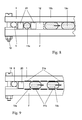
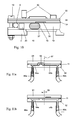
- FIGS. 8 to 10 do not show a complete embodiment of the microfluidic system, but serve to understand the transport mechanisms through the channels of the system.
- FIG. 1 is first shown schematically a known type.
- a base plate 2 micro channels and cavities are incorporated, for example as in FIG. 1 schematically shown as a cross section through two adjacent channels 14a and 14b.
- the two fluid channels 14a and 14b are closed at the top by a common cover plate 1.
- This cover places high demands on a fluid-tight connection 3 of the base plate 2 with the cover plate 1.
- at the edges 15 there is a risk of ingress of sample fluid 10, if a capillary gap is created by an insufficient connection between cover plate 1 and base plate.
- the cover plate 1 is connected to the base plate 2, for example by gluing, again there is a risk of adhesive entering the channel 14a or 14b.
- FIG. 2 shows the inventive structure of the assembled and disassembled microfluidic system.
- a capillary gap which is filled with a sealing fluid 11 prevents the sample fluid 10 from entering the capillary gap between the base plate 2 and the cover plate 1.
- the sealing fluid 11 in this case is a nonpolar fluid. Due to the coating of the surface, the sample fluid 10 is not able to displace the nonpolar sealing fluid 11 from the capillary gap.
- the hydrophobic coatings of the surfaces are not necessary if the cover plate 1 and the base plate 2 are made of materials whose surfaces are hydrophobic per se.
- the coating of the facing surfaces of the cover plate 1 and the base plate 2 must be hydrophilic and the sealing fluid 11 must be a polar fluid.
- a sufficiently small capillary gap can for example already be produced by a sufficient roughness of the surfaces of the cover plate 1 and the base plate 2. Between the sealing fluid 11 and the sample fluid 10, a meniscus 16 is formed.
- FIG. 3 an overall structure of the system is shown.
- the base plate 2 and the cover plate 1 are flat.
- the formation of a channel structure is carried out in this example by a structured channel plate 20, which is advantageously made of a Teflon plate, in which the channel structure has been cut, for example by means of a laser.
- the channel plate must have hydrophobic (as in the case of Teflon) or hydrophilic surface properties.
- Fluid connection holes 7 in the base plate 2 provide a fluidic contact via hose connections 9.
- the actual channel system which in the embodiment according to Fig. 3 through the base plate 2, the cover plate 1 and the Channel plate 20 is formed, is closed by a peripheral seal 6, to prevent sealing fluid 11 flows through the capillary gap on the edges of the base plate 2 or cover plate 1 to the outside.
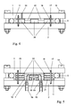
- the microfluidic system will, as in FIG. 4 shown as a cross section, compressed by clamping screws 19.
- the resulting width of the Kapillarspalte between the base plate 2 and the channel plate 20 and the cover plate 1 is first determined by the compression of the frame seal 6 and ultimately by the roughness of the plates.
- the mutually facing surfaces of the channel plate 20, cover plate 1 and base plate 2 can be roughened, so that sets a defined capillary gap.
- cover plate 1 and optionally existing channel plates 20 is filled with sealing fluid 11.
- a structured layer having a thickness which corresponds to the desired width of the capillary gap is applied to one or more of the plates 1, 2, 20 to 23 to produce a defined capillary gap between base plate 2, channel plate 20 and cover plate 1.
- the easy opening and closing of the microfluidic system by a screw or clamp connection is also a basis for an improved flooding of the channel structure.
- flooding is also possible with avoidance of air inclusions, especially in the case of complex microchannel structures changing channel cross-sections, chambers and partially hydrophobic and hydrophilic surfaces problematic.
- the inventive method proposes to make the mounting and clamping of the plates 1, 2 and 20 in a container filled with sealing fluid. Following this process, not only the capillary gaps between the individual plates 1, 2 and 20 are filled with sealing fluid, but also the fluid channels 14 themselves. After the closure of the microfluidic system by supplying sample fluid 10, the sealing fluid 11 contained in the channels 14 is displaced ,
- FIG. 5 a further embodiment of the invention is shown.
- a plurality of structured channel plates 21, 22, 23 are superimposed.
- crossings of fluid paths in the manner of a multi-level printed circuit board can be produced.
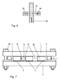
- a fluid path 25 is considered in which a sample fluid 10 enters the microfluidic system at the hose connection 9a, passes through holes 7 in the channel plates 21 and 22 into the plane of the channel plate 23, in this plane the fluid path 26 in the plane of the channel plate 21 crosses and leaves the microfluidic system through hose connection 9b again.
- FIG. 5 described plate assembly proposes the inventive method to make the mounting and clamping of the plates 1, 2, 20 to 23 in a container filled with sealing fluid.
- FIG. 6 illustrates in a plan view of the course of the two intersecting fluid paths 25 and 26. This makes it possible to integrate even relatively complex channel structures with a variety of functions in a microfluidic system.
- FIG. 7 Another embodiment of the invention for a 2-phase fluidic system is disclosed in US Pat FIG. 7 shown.
- 2-phase fluidic systems are characterized by a segmented sample stream.
- a compartment 13, consisting of a polar fluid, for example, with entrapped organic or inorganic material is transported by means of a non-polar transport fluid 12 through the channel system. Due to the immiscibility of the transport fluid 12 and the sample fluid 10, stable microspheres formed by surface tension are formed.
- the sealing fluid 11 is in turn designed as a polar fluid whose wettability of the surfaces is higher than that of the likewise polar sample fluid 10.
- This embodiment assumes that the surfaces 5 of the base plate 2, channel plate 20 and cover plate 1 structured hydrophobic and hydrophilic coated are. In the actual channels 14a and 14b no wetting of the channel walls by the polar sample fluid 10 may be possible.
- Another advantage of the open design of the microfluidic system according to the invention is that such a structured coating is possible with reasonable effort.
- the transport fluid 12 of a 2-phase system is also used as a sealing fluid. Due to the high flow resistance in the narrow capillary gap with respect to the flow resistance in the actual channel 14, the overflow of transport fluid 12 through the capillary gap can be avoided, whereby the distance between successive compartments 13b and 13c remains constant.
- the compartments are driven by a dielectrophoretic drive.
- cover plate 1 and base plate 2 are provided with electrode pairs 31a and 31b, which generate a changing (eg, wandering) electric field by a corresponding circuit and move the compartments 13a and 13b.
- the cover plate 1 is designed, for example, as a multi-level printed circuit board, which on the one hand carries electronic components such as amplifiers, AD converters or signal processors and electrically interconnects, on the other side on the fluid channels facing side sensor surfaces 35 with, for example, biologically active surfaces, pH sensors or other types of sensors wearing.
- the essence of the invention makes it possible to activate after the installation of the microfluidic system according to the invention, the defined sensors arranged, unless they were activated prior to assembly after assembly or to reactivate during the process duration. The same applies to, for example, the functionalization and calibration of the sensors.
- This exemplary illustration again shows the advantages of the microfluidic system according to the invention by combining an integrative, highly complex design with the property of simple assembly and disassembly.
- the base plate 2 or the cover plate 1 may be made of transparent material.
- this optical window 27 may be provided with a imaging feature in the form of a lens to achieve a high aperture. For example, an evaluation of compartments can take place through the optical window 27.
- a round base plate 52 is also provided with a round cover plate 51. Both the base plate 52 and the cover plate 51 are structured and contain different connection channels 54 and 55.
- the fluid flow of a sample fluid is, for example, from the connection tube 59a via the inflow channel 54a, the connection channel 55, the outflow channel 54b and the connecting tube 59b.
- the capillarity of the sealing fluid 11 in the gap between the base plate 52 and the cover plate 51 prevents leakage of the sample fluid at the junction between the base plate 52 and cover plate 51.
- FIG. 12 A wide embodiment of the fluid switch is in FIG. 12 shown.
- the fluid flow of a sample fluid is fed via a hose connection 61 to the microsystem, which again consists, for example, of a cover plate 51 and a base plate 52.
- the hose connection 61 is located in the axis 57, around which the base plate 52 can be rotated relative to the cover plate 51.
- the hose connection 62 in the base plate 51 which is connected via a hose connection 63 with a further hose connection 64.
- the hose connection 64 is located at a distance from the axis of rotation 57 and moves during rotation of the base plate 52 relative to the cover plate 51 on a circular arc.
- hose connections 65a to 65d At the same distance from the axis of rotation 57 are in the cover plate more hose connections 65a to 65d, such as FIG. 13 shows.
- a total of four hose connections 65a to 65d are provided, which are offset by 90 ° and have an equal distance from the axis of rotation 57 in the center of the circular base plate 52 and cover plate 51.
- the hose connection 64 now corresponds to one of the hose connections 65a to 65d, which can be assisted, for example, by a detent, then a fluidic connection is established for the fluid flow of the sample fluid to one of the selected hose connections 65a to 65d.
- different sample fluids can be supplied, one of which can be selected by turning the base plate 52 relative to the cover plate 51 and discharged through the drain hose 60.
- FIGS. 14 and 15 Another variant of a fluid switch is in the FIGS. 14 and 15 shown.
- the axis of rotation 57 of the circular cover and base plate 51 and 52 is again in alignment with the central hose connection 73, the here is arranged in a base plate 72.
- the base plate 72 In the base plate 72 are further, for example, four fluid ports 74a to 74d, which have an equal distance from the axis of rotation 57 and the hose connection 73.
- the cover plate 71 there is an angularly arranged connecting channel 76, which supplies position-dependent a sample flow supplied through the fluid connection 73 to two selected fluid connections 74a to 74d.
Landscapes
- Chemical & Material Sciences (AREA)
- Health & Medical Sciences (AREA)
- Chemical Kinetics & Catalysis (AREA)
- Dispersion Chemistry (AREA)
- Analytical Chemistry (AREA)
- Clinical Laboratory Science (AREA)
- General Health & Medical Sciences (AREA)
- Hematology (AREA)
- Organic Chemistry (AREA)
- Physical Or Chemical Processes And Apparatus (AREA)
- Automatic Analysis And Handling Materials Therefor (AREA)
Applications Claiming Priority (2)
| Application Number | Priority Date | Filing Date | Title |
|---|---|---|---|
| DE102009020449 | 2009-05-08 | ||
| DE102009024048A DE102009024048B3 (de) | 2009-05-08 | 2009-06-05 | Montier- und demontierbares Mikrofluidiksystem und Verfahren zur Flutung des Systems |
Publications (2)
| Publication Number | Publication Date |
|---|---|
| EP2248588A1 true EP2248588A1 (fr) | 2010-11-10 |
| EP2248588B1 EP2248588B1 (fr) | 2015-07-08 |
Family
ID=42338966
Family Applications (1)
| Application Number | Title | Priority Date | Filing Date |
|---|---|---|---|
| EP10162009.4A Not-in-force EP2248588B1 (fr) | 2009-05-08 | 2010-05-05 | Système microfluidique pouvant être monté et démonté et procédé de noyage du système |
Country Status (2)
| Country | Link |
|---|---|
| EP (1) | EP2248588B1 (fr) |
| DE (1) | DE102009024048B3 (fr) |
Cited By (4)
| Publication number | Priority date | Publication date | Assignee | Title |
|---|---|---|---|---|
| CN103313794A (zh) * | 2010-11-30 | 2013-09-18 | 康宁股份有限公司 | 玻璃微结构的直接密封 |
| CN113710352A (zh) * | 2019-01-31 | 2021-11-26 | 赛普公司 | 微流体装置和用于提供双乳液液滴的方法 |
| DE102021116887A1 (de) | 2021-06-30 | 2023-01-05 | Institut für Bioprozess- und Analysenmesstechnik e.V. | Anordnung zum Generieren von Fluidsequenzen in einem Multifluidtransportkanal zum Konditionieren und Detektieren der in dem Multifluidtransportkanal generierten Fluidsequenzen |
| US11565261B2 (en) | 2018-03-27 | 2023-01-31 | Robert Bosch Gmbh | Method and microfluidic device for aliquoting a sample liquid using a sealing liquid, method for producing a microfluidic device and microfluidic system |
Families Citing this family (4)
| Publication number | Priority date | Publication date | Assignee | Title |
|---|---|---|---|---|
| WO2015003037A1 (fr) * | 2013-07-03 | 2015-01-08 | Wyatt Technology Corporation | Procédé et appareil pour contrôler un report d'échantillon dans des instruments d'analyse |
| DE102017211451B4 (de) | 2017-07-05 | 2019-03-21 | Robert Bosch Gmbh | Mikromechanische Sensorvorrichtung und entsprechendes Herstellungsverfahren |
| CN110252221B (zh) * | 2019-05-19 | 2024-07-05 | 南京汇科高分子材料有限公司 | 用于生产改性异氰酸酯的反应釜 |
| WO2023107123A1 (fr) * | 2021-12-10 | 2023-06-15 | Hewlett-Packard Development Company, L.P. | Dispositifs microfluidiques à actionneurs diélectrophorétiques |
Citations (13)
| Publication number | Priority date | Publication date | Assignee | Title |
|---|---|---|---|---|
| DE69114838T2 (de) | 1990-05-10 | 1996-06-05 | Pharmacia Biotech Ab | Mikrostruktur für fluide und verfahren zu ihrer herstellung. |
| US5571410A (en) | 1994-10-19 | 1996-11-05 | Hewlett Packard Company | Fully integrated miniaturized planar liquid sample handling and analysis device |
| DE19648695C2 (de) | 1996-11-25 | 1999-07-22 | Abb Patent Gmbh | Vorrichtung zur automatischen und kontinuierlichen Analyse von Flüssigkeitsproben |
| US5964239A (en) | 1996-05-23 | 1999-10-12 | Hewlett-Packard Company | Housing assembly for micromachined fluid handling structure |
| US6399394B1 (en) * | 1999-06-30 | 2002-06-04 | Agilent Technologies, Inc. | Testing multiple fluid samples with multiple biopolymer arrays |
| US6450203B1 (en) | 2000-07-07 | 2002-09-17 | Micralyne Inc. | Sealed microfluidic devices |
| WO2003062133A2 (fr) * | 2002-01-18 | 2003-07-31 | Avery Dennison Corporation | Structures de microchambres recouvertes |
| US20030165079A1 (en) | 2001-12-11 | 2003-09-04 | Kuan Chen | Swirling-flow micro mixer and method |
| DE19927533B4 (de) | 1999-06-16 | 2004-03-04 | Merck Patent Gmbh | Miniaturisiertes Analysensystem |
| US20050226771A1 (en) * | 2003-09-19 | 2005-10-13 | Lehto Dennis A | High speed microplate transfer |
| US20050272142A1 (en) * | 2004-04-14 | 2005-12-08 | Hitachi Maxwell, Ltd. | Fluid vessel |
| WO2006046164A1 (fr) * | 2004-10-27 | 2006-05-04 | Koninklijke Philips Electronics N. V. | Contenant pour fluides compose de deux plaques |
| US20090224482A1 (en) * | 2008-03-04 | 2009-09-10 | Life Technologies Corporation | Custom Flow Cell Gasket and Assemblies and Methods Thereof |
Family Cites Families (3)
| Publication number | Priority date | Publication date | Assignee | Title |
|---|---|---|---|---|
| EP1721658B2 (fr) * | 2001-02-23 | 2020-08-05 | Japan Science and Technology Agency | Procédé et appareil pour la production de micro-capsules |
| WO2005073410A2 (fr) * | 2004-01-28 | 2005-08-11 | 454 Corporation | Amplification d'acide nucleique avec emulsion a flux continu |
| DE102006053451B4 (de) * | 2006-11-11 | 2008-11-27 | Microfluidic Chipshop Gmbh | Mikrofluidische Plattform zur Temperierung von Substanzen und/oder zur Durchführung von zu temperierenden Reaktionen |
-
2009
- 2009-06-05 DE DE102009024048A patent/DE102009024048B3/de not_active Expired - Fee Related
-
2010
- 2010-05-05 EP EP10162009.4A patent/EP2248588B1/fr not_active Not-in-force
Patent Citations (13)
| Publication number | Priority date | Publication date | Assignee | Title |
|---|---|---|---|---|
| DE69114838T2 (de) | 1990-05-10 | 1996-06-05 | Pharmacia Biotech Ab | Mikrostruktur für fluide und verfahren zu ihrer herstellung. |
| US5571410A (en) | 1994-10-19 | 1996-11-05 | Hewlett Packard Company | Fully integrated miniaturized planar liquid sample handling and analysis device |
| US5964239A (en) | 1996-05-23 | 1999-10-12 | Hewlett-Packard Company | Housing assembly for micromachined fluid handling structure |
| DE19648695C2 (de) | 1996-11-25 | 1999-07-22 | Abb Patent Gmbh | Vorrichtung zur automatischen und kontinuierlichen Analyse von Flüssigkeitsproben |
| DE19927533B4 (de) | 1999-06-16 | 2004-03-04 | Merck Patent Gmbh | Miniaturisiertes Analysensystem |
| US6399394B1 (en) * | 1999-06-30 | 2002-06-04 | Agilent Technologies, Inc. | Testing multiple fluid samples with multiple biopolymer arrays |
| US6450203B1 (en) | 2000-07-07 | 2002-09-17 | Micralyne Inc. | Sealed microfluidic devices |
| US20030165079A1 (en) | 2001-12-11 | 2003-09-04 | Kuan Chen | Swirling-flow micro mixer and method |
| WO2003062133A2 (fr) * | 2002-01-18 | 2003-07-31 | Avery Dennison Corporation | Structures de microchambres recouvertes |
| US20050226771A1 (en) * | 2003-09-19 | 2005-10-13 | Lehto Dennis A | High speed microplate transfer |
| US20050272142A1 (en) * | 2004-04-14 | 2005-12-08 | Hitachi Maxwell, Ltd. | Fluid vessel |
| WO2006046164A1 (fr) * | 2004-10-27 | 2006-05-04 | Koninklijke Philips Electronics N. V. | Contenant pour fluides compose de deux plaques |
| US20090224482A1 (en) * | 2008-03-04 | 2009-09-10 | Life Technologies Corporation | Custom Flow Cell Gasket and Assemblies and Methods Thereof |
Cited By (7)
| Publication number | Priority date | Publication date | Assignee | Title |
|---|---|---|---|---|
| CN103313794A (zh) * | 2010-11-30 | 2013-09-18 | 康宁股份有限公司 | 玻璃微结构的直接密封 |
| CN103313794B (zh) * | 2010-11-30 | 2015-07-29 | 康宁股份有限公司 | 玻璃微结构的直接密封 |
| US11565261B2 (en) | 2018-03-27 | 2023-01-31 | Robert Bosch Gmbh | Method and microfluidic device for aliquoting a sample liquid using a sealing liquid, method for producing a microfluidic device and microfluidic system |
| CN113710352A (zh) * | 2019-01-31 | 2021-11-26 | 赛普公司 | 微流体装置和用于提供双乳液液滴的方法 |
| CN113710352B (zh) * | 2019-01-31 | 2024-03-26 | 赛普公司 | 微流体装置和用于提供双乳液液滴的方法 |
| DE102021116887A1 (de) | 2021-06-30 | 2023-01-05 | Institut für Bioprozess- und Analysenmesstechnik e.V. | Anordnung zum Generieren von Fluidsequenzen in einem Multifluidtransportkanal zum Konditionieren und Detektieren der in dem Multifluidtransportkanal generierten Fluidsequenzen |
| EP4122604A2 (fr) | 2021-06-30 | 2023-01-25 | Institut für Bioprozess- und Analysenmesstechnik e.V. | Dispositif et procédé de génération des séquences de fluide dans un canal de transport de fluides multiples et de conditionnement et de détection des séquences de fluide générées dans le canal de transport de fluides multiples |
Also Published As
| Publication number | Publication date |
|---|---|
| DE102009024048B3 (de) | 2010-08-19 |
| EP2248588B1 (fr) | 2015-07-08 |
Similar Documents
| Publication | Publication Date | Title |
|---|---|---|
| EP2248588B1 (fr) | Système microfluidique pouvant être monté et démonté et procédé de noyage du système | |
| EP2576065B1 (fr) | Cellule a ecoulement avec cavite et diaphragme | |
| DE10227593B4 (de) | Strömungsschaltungs-Mikrobauelemente | |
| EP2821138B2 (fr) | Cellule d'écoulement avec substance de séchage intégrée | |
| EP2389529B1 (fr) | Soupape, en particulier pour un composant de la technique des microfluides | |
| EP1144095B1 (fr) | Dispositif de concentration et/ou de purification de macromolecules en solution et procede de fabrication d'un tel dispositif | |
| DE60208235T2 (de) | Mikrofluidische vorrichtungen mit verteilungseinlässen | |
| DE102009015395B4 (de) | Flusszelle zur Behandlung und/oder Untersuchung eines Fluids | |
| AT519382B1 (de) | Vorrichtung mit Drehventil zur Manipulation von Flüssigkeiten | |
| EP2796200B1 (fr) | Cartouche d'analyse microfluidique et procédé destiné à sa fabrication | |
| DE102011078961A1 (de) | System zum Separieren von Körperflüssigkeitsbestandteilen und Verfahren zum Herstellen eines derartigen Systems | |
| DE19933458A1 (de) | Einrichtung zum Handhaben von Flüssigkeitsproben, System zum Handhaben von Flüssigkeitsproben und Verfahren zum Herstellen der Einrichtung | |
| EP1062042A1 (fr) | Porte-echantillon | |
| EP3049186B1 (fr) | Dispositif d'analyse , procédé de fonctionnement du dispositif et procédé de sa fabrication | |
| DE102004063438A1 (de) | Neuartige mikrofluidische Probenträger | |
| EP2308589B1 (fr) | Structure micro-fluidique | |
| DE102009001257A1 (de) | Vorrichtung und Verfahren zur Handhabung von Flüssigkeiten | |
| DE19948087A1 (de) | Strukturierter Probenträger und Verfahren zu seiner Herstellung | |
| DE102015226417A1 (de) | Mikrofluidische Vorrichtung, Verfahren zum Herstellen und Verfahren zum Betreiben einer mikrofluidischen Vorrichtung | |
| EP1489404A1 (fr) | Méthode de production d'une cellule d'écoulement 3-D pour microscope | |
| WO2010031559A1 (fr) | Vanne microfluidique, pompe microfluidique, système microfluidique et procédé de production | |
| WO2023180422A1 (fr) | Dispositif microfluidique et procédé d'utilisation d'un dispositif microfluidique | |
| EP2522427B1 (fr) | Dispositif microfluidique et son procédé de fabrication | |
| EP2525225B1 (fr) | Installation et procédé d'analyse de la différentiation de cellules | |
| DE202014104510U1 (de) | Vorrichtung zum Vorlagern eines Fluids in einem mikrofluidischen System |
Legal Events
| Date | Code | Title | Description |
|---|---|---|---|
| PUAI | Public reference made under article 153(3) epc to a published international application that has entered the european phase |
Free format text: ORIGINAL CODE: 0009012 |
|
| AK | Designated contracting states |
Kind code of ref document: A1 Designated state(s): AL AT BE BG CH CY CZ DE DK EE ES FI FR GB GR HR HU IE IS IT LI LT LU LV MC MK MT NL NO PL PT RO SE SI SK SM TR |
|
| AX | Request for extension of the european patent |
Extension state: BA ME RS |
|
| 17P | Request for examination filed |
Effective date: 20110225 |
|
| 17Q | First examination report despatched |
Effective date: 20120711 |
|
| GRAP | Despatch of communication of intention to grant a patent |
Free format text: ORIGINAL CODE: EPIDOSNIGR1 |
|
| INTG | Intention to grant announced |
Effective date: 20150323 |
|
| RIN1 | Information on inventor provided before grant (corrected) |
Inventor name: WIEDEMEIER, STEFAN Inventor name: LEMKE, KAREN Inventor name: GASTROCK, GUNTER Inventor name: GRODRIAN, ANDREAS Inventor name: ROEMER, ROBERT |
|
| GRAS | Grant fee paid |
Free format text: ORIGINAL CODE: EPIDOSNIGR3 |
|
| GRAA | (expected) grant |
Free format text: ORIGINAL CODE: 0009210 |
|
| AK | Designated contracting states |
Kind code of ref document: B1 Designated state(s): AL AT BE BG CH CY CZ DE DK EE ES FI FR GB GR HR HU IE IS IT LI LT LU LV MC MK MT NL NO PL PT RO SE SI SK SM TR |
|
| REG | Reference to a national code |
Ref country code: GB Ref legal event code: FG4D Free format text: NOT ENGLISH |
|
| REG | Reference to a national code |
Ref country code: AT Ref legal event code: REF Ref document number: 734941 Country of ref document: AT Kind code of ref document: T Effective date: 20150715 Ref country code: CH Ref legal event code: EP |
|
| REG | Reference to a national code |
Ref country code: IE Ref legal event code: FG4D Free format text: LANGUAGE OF EP DOCUMENT: GERMAN |
|
| REG | Reference to a national code |
Ref country code: DE Ref legal event code: R096 Ref document number: 502010009806 Country of ref document: DE |
|
| REG | Reference to a national code |
Ref country code: NL Ref legal event code: MP Effective date: 20150708 |
|
| REG | Reference to a national code |
Ref country code: LT Ref legal event code: MG4D |
|
| PG25 | Lapsed in a contracting state [announced via postgrant information from national office to epo] |
Ref country code: GR Free format text: LAPSE BECAUSE OF FAILURE TO SUBMIT A TRANSLATION OF THE DESCRIPTION OR TO PAY THE FEE WITHIN THE PRESCRIBED TIME-LIMIT Effective date: 20151009 Ref country code: LV Free format text: LAPSE BECAUSE OF FAILURE TO SUBMIT A TRANSLATION OF THE DESCRIPTION OR TO PAY THE FEE WITHIN THE PRESCRIBED TIME-LIMIT Effective date: 20150708 Ref country code: LT Free format text: LAPSE BECAUSE OF FAILURE TO SUBMIT A TRANSLATION OF THE DESCRIPTION OR TO PAY THE FEE WITHIN THE PRESCRIBED TIME-LIMIT Effective date: 20150708 Ref country code: FI Free format text: LAPSE BECAUSE OF FAILURE TO SUBMIT A TRANSLATION OF THE DESCRIPTION OR TO PAY THE FEE WITHIN THE PRESCRIBED TIME-LIMIT Effective date: 20150708 Ref country code: NO Free format text: LAPSE BECAUSE OF FAILURE TO SUBMIT A TRANSLATION OF THE DESCRIPTION OR TO PAY THE FEE WITHIN THE PRESCRIBED TIME-LIMIT Effective date: 20151008 |
|
| PG25 | Lapsed in a contracting state [announced via postgrant information from national office to epo] |
Ref country code: PL Free format text: LAPSE BECAUSE OF FAILURE TO SUBMIT A TRANSLATION OF THE DESCRIPTION OR TO PAY THE FEE WITHIN THE PRESCRIBED TIME-LIMIT Effective date: 20150708 Ref country code: HR Free format text: LAPSE BECAUSE OF FAILURE TO SUBMIT A TRANSLATION OF THE DESCRIPTION OR TO PAY THE FEE WITHIN THE PRESCRIBED TIME-LIMIT Effective date: 20150708 Ref country code: PT Free format text: LAPSE BECAUSE OF FAILURE TO SUBMIT A TRANSLATION OF THE DESCRIPTION OR TO PAY THE FEE WITHIN THE PRESCRIBED TIME-LIMIT Effective date: 20151109 Ref country code: IS Free format text: LAPSE BECAUSE OF FAILURE TO SUBMIT A TRANSLATION OF THE DESCRIPTION OR TO PAY THE FEE WITHIN THE PRESCRIBED TIME-LIMIT Effective date: 20151108 Ref country code: ES Free format text: LAPSE BECAUSE OF FAILURE TO SUBMIT A TRANSLATION OF THE DESCRIPTION OR TO PAY THE FEE WITHIN THE PRESCRIBED TIME-LIMIT Effective date: 20150708 Ref country code: SE Free format text: LAPSE BECAUSE OF FAILURE TO SUBMIT A TRANSLATION OF THE DESCRIPTION OR TO PAY THE FEE WITHIN THE PRESCRIBED TIME-LIMIT Effective date: 20150708 |
|
| REG | Reference to a national code |
Ref country code: DE Ref legal event code: R097 Ref document number: 502010009806 Country of ref document: DE |
|
| PG25 | Lapsed in a contracting state [announced via postgrant information from national office to epo] |
Ref country code: DK Free format text: LAPSE BECAUSE OF FAILURE TO SUBMIT A TRANSLATION OF THE DESCRIPTION OR TO PAY THE FEE WITHIN THE PRESCRIBED TIME-LIMIT Effective date: 20150708 Ref country code: EE Free format text: LAPSE BECAUSE OF FAILURE TO SUBMIT A TRANSLATION OF THE DESCRIPTION OR TO PAY THE FEE WITHIN THE PRESCRIBED TIME-LIMIT Effective date: 20150708 Ref country code: SK Free format text: LAPSE BECAUSE OF FAILURE TO SUBMIT A TRANSLATION OF THE DESCRIPTION OR TO PAY THE FEE WITHIN THE PRESCRIBED TIME-LIMIT Effective date: 20150708 Ref country code: IT Free format text: LAPSE BECAUSE OF FAILURE TO SUBMIT A TRANSLATION OF THE DESCRIPTION OR TO PAY THE FEE WITHIN THE PRESCRIBED TIME-LIMIT Effective date: 20150708 Ref country code: CZ Free format text: LAPSE BECAUSE OF FAILURE TO SUBMIT A TRANSLATION OF THE DESCRIPTION OR TO PAY THE FEE WITHIN THE PRESCRIBED TIME-LIMIT Effective date: 20150708 |
|
| PLBE | No opposition filed within time limit |
Free format text: ORIGINAL CODE: 0009261 |
|
| STAA | Information on the status of an ep patent application or granted ep patent |
Free format text: STATUS: NO OPPOSITION FILED WITHIN TIME LIMIT |
|
| REG | Reference to a national code |
Ref country code: FR Ref legal event code: PLFP Year of fee payment: 7 |
|
| PG25 | Lapsed in a contracting state [announced via postgrant information from national office to epo] |
Ref country code: RO Free format text: LAPSE BECAUSE OF FAILURE TO SUBMIT A TRANSLATION OF THE DESCRIPTION OR TO PAY THE FEE WITHIN THE PRESCRIBED TIME-LIMIT Effective date: 20150708 |
|
| 26N | No opposition filed |
Effective date: 20160411 |
|
| PG25 | Lapsed in a contracting state [announced via postgrant information from national office to epo] |
Ref country code: BE Free format text: LAPSE BECAUSE OF NON-PAYMENT OF DUE FEES Effective date: 20160531 Ref country code: SI Free format text: LAPSE BECAUSE OF FAILURE TO SUBMIT A TRANSLATION OF THE DESCRIPTION OR TO PAY THE FEE WITHIN THE PRESCRIBED TIME-LIMIT Effective date: 20150708 |
|
| REG | Reference to a national code |
Ref country code: DE Ref legal event code: R119 Ref document number: 502010009806 Country of ref document: DE |
|
| PG25 | Lapsed in a contracting state [announced via postgrant information from national office to epo] |
Ref country code: LU Free format text: LAPSE BECAUSE OF FAILURE TO SUBMIT A TRANSLATION OF THE DESCRIPTION OR TO PAY THE FEE WITHIN THE PRESCRIBED TIME-LIMIT Effective date: 20160505 |
|
| REG | Reference to a national code |
Ref country code: IE Ref legal event code: MM4A |
|
| PG25 | Lapsed in a contracting state [announced via postgrant information from national office to epo] |
Ref country code: DE Free format text: LAPSE BECAUSE OF NON-PAYMENT OF DUE FEES Effective date: 20161201 |
|
| REG | Reference to a national code |
Ref country code: FR Ref legal event code: PLFP Year of fee payment: 8 |
|
| PG25 | Lapsed in a contracting state [announced via postgrant information from national office to epo] |
Ref country code: IE Free format text: LAPSE BECAUSE OF NON-PAYMENT OF DUE FEES Effective date: 20160505 |
|
| PG25 | Lapsed in a contracting state [announced via postgrant information from national office to epo] |
Ref country code: NL Free format text: LAPSE BECAUSE OF FAILURE TO SUBMIT A TRANSLATION OF THE DESCRIPTION OR TO PAY THE FEE WITHIN THE PRESCRIBED TIME-LIMIT Effective date: 20150708 |
|
| REG | Reference to a national code |
Ref country code: AT Ref legal event code: MM01 Ref document number: 734941 Country of ref document: AT Kind code of ref document: T Effective date: 20160505 |
|
| PG25 | Lapsed in a contracting state [announced via postgrant information from national office to epo] |
Ref country code: AT Free format text: LAPSE BECAUSE OF NON-PAYMENT OF DUE FEES Effective date: 20160505 |
|
| REG | Reference to a national code |
Ref country code: FR Ref legal event code: PLFP Year of fee payment: 9 |
|
| PG25 | Lapsed in a contracting state [announced via postgrant information from national office to epo] |
Ref country code: SM Free format text: LAPSE BECAUSE OF FAILURE TO SUBMIT A TRANSLATION OF THE DESCRIPTION OR TO PAY THE FEE WITHIN THE PRESCRIBED TIME-LIMIT Effective date: 20150708 Ref country code: HU Free format text: LAPSE BECAUSE OF FAILURE TO SUBMIT A TRANSLATION OF THE DESCRIPTION OR TO PAY THE FEE WITHIN THE PRESCRIBED TIME-LIMIT; INVALID AB INITIO Effective date: 20100505 Ref country code: CY Free format text: LAPSE BECAUSE OF FAILURE TO SUBMIT A TRANSLATION OF THE DESCRIPTION OR TO PAY THE FEE WITHIN THE PRESCRIBED TIME-LIMIT Effective date: 20150708 |
|
| PG25 | Lapsed in a contracting state [announced via postgrant information from national office to epo] |
Ref country code: MK Free format text: LAPSE BECAUSE OF FAILURE TO SUBMIT A TRANSLATION OF THE DESCRIPTION OR TO PAY THE FEE WITHIN THE PRESCRIBED TIME-LIMIT Effective date: 20150708 Ref country code: MC Free format text: LAPSE BECAUSE OF FAILURE TO SUBMIT A TRANSLATION OF THE DESCRIPTION OR TO PAY THE FEE WITHIN THE PRESCRIBED TIME-LIMIT Effective date: 20150708 Ref country code: TR Free format text: LAPSE BECAUSE OF FAILURE TO SUBMIT A TRANSLATION OF THE DESCRIPTION OR TO PAY THE FEE WITHIN THE PRESCRIBED TIME-LIMIT Effective date: 20150708 Ref country code: MT Free format text: LAPSE BECAUSE OF FAILURE TO SUBMIT A TRANSLATION OF THE DESCRIPTION OR TO PAY THE FEE WITHIN THE PRESCRIBED TIME-LIMIT Effective date: 20150708 |
|
| PG25 | Lapsed in a contracting state [announced via postgrant information from national office to epo] |
Ref country code: BG Free format text: LAPSE BECAUSE OF FAILURE TO SUBMIT A TRANSLATION OF THE DESCRIPTION OR TO PAY THE FEE WITHIN THE PRESCRIBED TIME-LIMIT Effective date: 20150708 |
|
| PGFP | Annual fee paid to national office [announced via postgrant information from national office to epo] |
Ref country code: CH Payment date: 20180523 Year of fee payment: 9 |
|
| PGFP | Annual fee paid to national office [announced via postgrant information from national office to epo] |
Ref country code: FR Payment date: 20180523 Year of fee payment: 9 |
|
| PG25 | Lapsed in a contracting state [announced via postgrant information from national office to epo] |
Ref country code: AL Free format text: LAPSE BECAUSE OF FAILURE TO SUBMIT A TRANSLATION OF THE DESCRIPTION OR TO PAY THE FEE WITHIN THE PRESCRIBED TIME-LIMIT Effective date: 20150708 |
|
| PGFP | Annual fee paid to national office [announced via postgrant information from national office to epo] |
Ref country code: GB Payment date: 20180523 Year of fee payment: 9 |
|
| REG | Reference to a national code |
Ref country code: CH Ref legal event code: PL |
|
| GBPC | Gb: european patent ceased through non-payment of renewal fee |
Effective date: 20190505 |
|
| PG25 | Lapsed in a contracting state [announced via postgrant information from national office to epo] |
Ref country code: LI Free format text: LAPSE BECAUSE OF NON-PAYMENT OF DUE FEES Effective date: 20190531 Ref country code: CH Free format text: LAPSE BECAUSE OF NON-PAYMENT OF DUE FEES Effective date: 20190531 |
|
| PG25 | Lapsed in a contracting state [announced via postgrant information from national office to epo] |
Ref country code: GB Free format text: LAPSE BECAUSE OF NON-PAYMENT OF DUE FEES Effective date: 20190505 |
|
| PG25 | Lapsed in a contracting state [announced via postgrant information from national office to epo] |
Ref country code: FR Free format text: LAPSE BECAUSE OF NON-PAYMENT OF DUE FEES Effective date: 20190531 |