EP4122604A2 - Dispositif et procédé de génération des séquences de fluide dans un canal de transport de fluides multiples et de conditionnement et de détection des séquences de fluide générées dans le canal de transport de fluides multiples - Google Patents
Dispositif et procédé de génération des séquences de fluide dans un canal de transport de fluides multiples et de conditionnement et de détection des séquences de fluide générées dans le canal de transport de fluides multiples Download PDFInfo
- Publication number
- EP4122604A2 EP4122604A2 EP22182285.1A EP22182285A EP4122604A2 EP 4122604 A2 EP4122604 A2 EP 4122604A2 EP 22182285 A EP22182285 A EP 22182285A EP 4122604 A2 EP4122604 A2 EP 4122604A2
- Authority
- EP
- European Patent Office
- Prior art keywords
- fluid
- transport channel
- mftk
- fluid transport
- channel
- Prior art date
- Legal status (The legal status is an assumption and is not a legal conclusion. Google has not performed a legal analysis and makes no representation as to the accuracy of the status listed.)
- Pending
Links
Images


Classifications
-
- B—PERFORMING OPERATIONS; TRANSPORTING
- B01—PHYSICAL OR CHEMICAL PROCESSES OR APPARATUS IN GENERAL
- B01L—CHEMICAL OR PHYSICAL LABORATORY APPARATUS FOR GENERAL USE
- B01L3/00—Containers or dishes for laboratory use, e.g. laboratory glassware; Droppers
- B01L3/56—Labware specially adapted for transferring fluids
- B01L3/567—Valves, taps or stop-cocks
-
- B—PERFORMING OPERATIONS; TRANSPORTING
- B01—PHYSICAL OR CHEMICAL PROCESSES OR APPARATUS IN GENERAL
- B01L—CHEMICAL OR PHYSICAL LABORATORY APPARATUS FOR GENERAL USE
- B01L3/00—Containers or dishes for laboratory use, e.g. laboratory glassware; Droppers
- B01L3/02—Burettes; Pipettes
- B01L3/0241—Drop counters; Drop formers
- B01L3/0265—Drop counters; Drop formers using valves to interrupt or meter fluid flow, e.g. using solenoids or metering valves
-
- B—PERFORMING OPERATIONS; TRANSPORTING
- B01—PHYSICAL OR CHEMICAL PROCESSES OR APPARATUS IN GENERAL
- B01L—CHEMICAL OR PHYSICAL LABORATORY APPARATUS FOR GENERAL USE
- B01L3/00—Containers or dishes for laboratory use, e.g. laboratory glassware; Droppers
- B01L3/02—Burettes; Pipettes
- B01L3/0289—Apparatus for withdrawing or distributing predetermined quantities of fluid
- B01L3/0293—Apparatus for withdrawing or distributing predetermined quantities of fluid for liquids
-
- F—MECHANICAL ENGINEERING; LIGHTING; HEATING; WEAPONS; BLASTING
- F16—ENGINEERING ELEMENTS AND UNITS; GENERAL MEASURES FOR PRODUCING AND MAINTAINING EFFECTIVE FUNCTIONING OF MACHINES OR INSTALLATIONS; THERMAL INSULATION IN GENERAL
- F16K—VALVES; TAPS; COCKS; ACTUATING-FLOATS; DEVICES FOR VENTING OR AERATING
- F16K11/00—Multiple-way valves, e.g. mixing valves; Pipe fittings incorporating such valves
- F16K11/02—Multiple-way valves, e.g. mixing valves; Pipe fittings incorporating such valves with all movable sealing faces moving as one unit
- F16K11/06—Multiple-way valves, e.g. mixing valves; Pipe fittings incorporating such valves with all movable sealing faces moving as one unit comprising only sliding valves, i.e. sliding closure elements
- F16K11/072—Multiple-way valves, e.g. mixing valves; Pipe fittings incorporating such valves with all movable sealing faces moving as one unit comprising only sliding valves, i.e. sliding closure elements with pivoted closure members
- F16K11/076—Multiple-way valves, e.g. mixing valves; Pipe fittings incorporating such valves with all movable sealing faces moving as one unit comprising only sliding valves, i.e. sliding closure elements with pivoted closure members with sealing faces shaped as surfaces of solids of revolution
-
- F—MECHANICAL ENGINEERING; LIGHTING; HEATING; WEAPONS; BLASTING
- F16—ENGINEERING ELEMENTS AND UNITS; GENERAL MEASURES FOR PRODUCING AND MAINTAINING EFFECTIVE FUNCTIONING OF MACHINES OR INSTALLATIONS; THERMAL INSULATION IN GENERAL
- F16K—VALVES; TAPS; COCKS; ACTUATING-FLOATS; DEVICES FOR VENTING OR AERATING
- F16K11/00—Multiple-way valves, e.g. mixing valves; Pipe fittings incorporating such valves
- F16K11/02—Multiple-way valves, e.g. mixing valves; Pipe fittings incorporating such valves with all movable sealing faces moving as one unit
- F16K11/08—Multiple-way valves, e.g. mixing valves; Pipe fittings incorporating such valves with all movable sealing faces moving as one unit comprising only taps or cocks
- F16K11/085—Multiple-way valves, e.g. mixing valves; Pipe fittings incorporating such valves with all movable sealing faces moving as one unit comprising only taps or cocks with cylindrical plug
- F16K11/0853—Multiple-way valves, e.g. mixing valves; Pipe fittings incorporating such valves with all movable sealing faces moving as one unit comprising only taps or cocks with cylindrical plug having all the connecting conduits situated in a single plane perpendicular to the axis of the plug
-
- G—PHYSICS
- G01—MEASURING; TESTING
- G01N—INVESTIGATING OR ANALYSING MATERIALS BY DETERMINING THEIR CHEMICAL OR PHYSICAL PROPERTIES
- G01N35/00—Automatic analysis not limited to methods or materials provided for in any single one of groups G01N1/00 - G01N33/00; Handling materials therefor
- G01N35/10—Devices for transferring samples or any liquids to, in, or from, the analysis apparatus, e.g. suction devices, injection devices
- G01N35/1095—Devices for transferring samples or any liquids to, in, or from, the analysis apparatus, e.g. suction devices, injection devices for supplying the samples to flow-through analysers
- G01N35/1097—Devices for transferring samples or any liquids to, in, or from, the analysis apparatus, e.g. suction devices, injection devices for supplying the samples to flow-through analysers characterised by the valves
-
- B—PERFORMING OPERATIONS; TRANSPORTING
- B01—PHYSICAL OR CHEMICAL PROCESSES OR APPARATUS IN GENERAL
- B01L—CHEMICAL OR PHYSICAL LABORATORY APPARATUS FOR GENERAL USE
- B01L2200/00—Solutions for specific problems relating to chemical or physical laboratory apparatus
- B01L2200/02—Adapting objects or devices to another
- B01L2200/028—Modular arrangements
-
- B—PERFORMING OPERATIONS; TRANSPORTING
- B01—PHYSICAL OR CHEMICAL PROCESSES OR APPARATUS IN GENERAL
- B01L—CHEMICAL OR PHYSICAL LABORATORY APPARATUS FOR GENERAL USE
- B01L2200/00—Solutions for specific problems relating to chemical or physical laboratory apparatus
- B01L2200/06—Fluid handling related problems
- B01L2200/0673—Handling of plugs of fluid surrounded by immiscible fluid
-
- B—PERFORMING OPERATIONS; TRANSPORTING
- B01—PHYSICAL OR CHEMICAL PROCESSES OR APPARATUS IN GENERAL
- B01L—CHEMICAL OR PHYSICAL LABORATORY APPARATUS FOR GENERAL USE
- B01L2200/00—Solutions for specific problems relating to chemical or physical laboratory apparatus
- B01L2200/14—Process control and prevention of errors
- B01L2200/141—Preventing contamination, tampering
-
- B—PERFORMING OPERATIONS; TRANSPORTING
- B01—PHYSICAL OR CHEMICAL PROCESSES OR APPARATUS IN GENERAL
- B01L—CHEMICAL OR PHYSICAL LABORATORY APPARATUS FOR GENERAL USE
- B01L2300/00—Additional constructional details
- B01L2300/08—Geometry, shape and general structure
- B01L2300/0809—Geometry, shape and general structure rectangular shaped
- B01L2300/0829—Multi-well plates; Microtitration plates
-
- B—PERFORMING OPERATIONS; TRANSPORTING
- B01—PHYSICAL OR CHEMICAL PROCESSES OR APPARATUS IN GENERAL
- B01L—CHEMICAL OR PHYSICAL LABORATORY APPARATUS FOR GENERAL USE
- B01L2400/00—Moving or stopping fluids
- B01L2400/06—Valves, specific forms thereof
- B01L2400/0622—Valves, specific forms thereof distribution valves, valves having multiple inlets and/or outlets, e.g. metering valves, multi-way valves
-
- B—PERFORMING OPERATIONS; TRANSPORTING
- B01—PHYSICAL OR CHEMICAL PROCESSES OR APPARATUS IN GENERAL
- B01L—CHEMICAL OR PHYSICAL LABORATORY APPARATUS FOR GENERAL USE
- B01L2400/00—Moving or stopping fluids
- B01L2400/06—Valves, specific forms thereof
- B01L2400/0633—Valves, specific forms thereof with moving parts
- B01L2400/0644—Valves, specific forms thereof with moving parts rotary valves
Definitions
- the invention further relates to an arrangement and a method for generating fluid sequences, consisting of fluid compartments, embedded in at least one other fluid that is immiscible with the fluid compartments, in at least one multi-fluid transport channel and/or for conditioning and/or detecting the fluid sequences generated in the multi-fluid transport channel .
- the invention is in the field of microfluidics and here in particular in the field of droplet-based microfluidics.
- the droplet-based microfluidics is very flexible, versatile and has a high degree of miniaturization. This makes it ideal for life science and chemistry and can be used in a variety of ways.
- Systems and processes based on microfluidic concepts are characterized by a large Range of applications from: from methods for the modification and analysis of viruses/phages, microorganisms, cells or entire cell networks to the synthesis of/organic substances, particles, compounds and complexes.
- Droplet-based microfluidics encompasses technologies used to process picoliter, nanoliter, and low-microliter fluid samples.
- a sample is not divided into reaction vessels as in conventional methods, but aliquoted in a phase that is immiscible with the sample.
- the samples are not aliquoted into individual vessels, but through the sample-immiscible phase (carrier fluid) into a microchannel, which as a multi-fluid transport channel has specific geometric and surface-specific properties. Due to the immiscibility of both phases (sample medium hydrophilic / carrier fluid hydrophobic or sample medium hydrophobic and carrier fluid hydrophilic), interfaces between the fluids are formed.
- the aliquoted sample is thus present in the carrier fluid in the form of separate fluid compartments (microreactors).
- the droplet-based microfluidics can be built up modularly, i.e. on the basis of a modular platform, which enables a high degree of flexibility.
- EP 2 248 588 A1 discloses an attachable and detachable microfluidic system for the microscale creation, cultivation, manipulation, analysis and preservation of single-phase and multiphase fluids and a method for flooding the system.
- DE 10 2011 088 741 A1 discloses an arrangement for carrying out a method for separating cells from a cell suspension, preferably blood cells, with target cells located in the cell suspension being marked with magnetic beads and then separated, having a two-fluid probe, an incubation conductor in which incubation takes place, a microchannel network , and a moving magnet assembly.
- EP 2 156 890 A2 relates to an arrangement and a method for compartmentalizing and for manipulating compartments.
- stable microspheres are generated from a gaseous or liquid fluid, which contain the sample material, such as inorganic substances in any aggregate state, bioactive molecules or cells or microorganisms and which are not affected by a microsphere miscible transport fluid, for example, for the purpose of chemical, biological and physical reaction, cultivation, manipulation in and with the compartment, storage and analysis.
- a microsphere miscible transport fluid for example, for the purpose of chemical, biological and physical reaction, cultivation, manipulation in and with the compartment, storage and analysis.
- WO2007071374 relates to a device for the transport of at least one compartment in a transport liquid in at least one transport channel, at least one inlet channel with a liquid different from the transport liquid opening into the transport channel, which is supplied by at least one first pump assigned to the transport channel for transporting the transport liquid, and by at least one pressure measuring device assigned to the transport channel and/or inlet channel for controlling the pump is marked.
- a method for forming and transporting at least one compartment is also disclosed.
- WO 2020/025679 A1 relates to a device for the optical characterization of fluids and/or objects enclosed therein in a microchannel, comprising a measuring cell, the microchannel being guided through the measuring cell, characterized in that the measuring cell is filled with a liquid, the microchannel is inside the measuring cell is located in the liquid, the fluid and/or objects enclosed therein can be moved in the microchannel and the microchannel within the measuring cell and/or the measuring cell with the microchannel can be moved manually or automatically.
- the invention further relates to a measuring cell for the device and method for the optical characterization of fluids and/or objects enclosed therein in a microchannel by means of the device according to the invention.
- the object of the invention was therefore to overcome the disadvantages of the prior art and to provide a device for coupling different system sections with different functions in a microfluidic arrangement. Due to the geometric dimensions of the fluid channels in the range of diameters between 100 ⁇ m and 3.2 mm, the device can be realized, for example, with precision mechanical manufacturing methods including injection molding and 3D printing processes.
- the object of the invention is achieved by providing a deflection module according to claim 1.
- the present invention includes a deflection module that includes a terminal stator that is in the form of a hollow cylinder with a closed bottom.
- the connection stator of the deflection module preferably has a material included in the group comprising polyetheretherketone (PEEK), polytetrafluoroethylene (PTFE) and combinations of these.
- PEEK polyetheretherketone
- PTFE polytetrafluoroethylene
- the material should be low-friction and dimensionally stable, and sterilizable to the extent required by the application.
- a fluid channel is arranged centrally in the base of the connecting stator. This is designed as a bore through which a suitable supply line or connection line can be introduced into the deflection module.
- a suitable supply line is, for example, a hose made of a hydrophobic material, since aqueous fluid compartments and oily carrier fluid are transported in the hose.
- a PTFE (polytetrafluoroethylene) hose or an FEP (perfluoroethylene propylene) hose is particularly suitable, which is fixed by means of a screw connection and optionally one or more sealing elements and sealed off from the environment.
- hydrophilic tubing is particularly suitable.
- the material of the hoses can therefore be adapted to the intended use of the deflection module.
- the tube surfaces that come into contact with the carrier fluid have corresponding materials with hydrophobic or hydrophilic properties. It should be noted that all of the hoses described below that are used in connection with the deflection module have the properties described.
- the deflection module has n fluid channels (mantle surface channels or bottom channels), where n ⁇ 2 and n E N .
- the lateral surface channels are arranged radially in the lateral surface of the connection stator.
- the bottom channels are arranged in a circle in the bottom of the connecting stator.
- ds the diameter of the switching rotor ie doubling the diameter of the hollow cylinder of the connecting stator can double the connecting channels.
- a minimum diameter ds min of the switching rotor of 30 mm is required.
- the lateral surface channels are preferably designed in the form of bores through the lateral surface, with the bores extending continuously into the open core of the hollow cylinder.
- the bottom channels are preferably designed as bores through the bottom of the connecting stator.
- the holes run right through the floor.
- Suitable hoses can be inserted into the deflection module through the bores. Suitable hoses are, for example, PTFE or FEP hoses, by means of which the droplet sequences are transported into or out of the deflection module. In the case of a hydrophilic carrier fluid and hydrophobic fluid compartments, hydrophilic hoses are preferably used accordingly, as already described.
- the deflection module has 2 to 64 lateral surface channels or base channels, preferably 2 to 16, particularly preferably 2 to 8 lateral surface channels or base channels.
- the switching rotor can be designed in one piece or also in multiple parts.
- the switching rotor formed in two parts. This embodiment has the advantage that a semi-circular transport channel can be introduced into one half of the switching rotor, for example by milling, with a transport channel with a circular cross-section being produced after the two halves have been assembled. The two halves can be joined together, for example, by means of a screw connection or alignment pins.
- the switching rotor is essentially cylindrical and has such a diameter and a height that the switching rotor can be introduced into the hollow space of the connecting stator with a precise fit.
- the switching rotor is movable, in particular rotatably mounted axially in the connecting stator.
- the switching rotor is positioned axially in the connecting stator with the aid of the stator cover.
- a positioning can be done, for example, with the help of at least one alignment pin.
- Two alignment pins are preferably used.
- the stator cover therefore has at least two bores for two alignment pins.
- the connecting stator also has at least two bores for two alignment pins.
- the adjustment pins are introduced into the bore of the stator cover and the connecting stator in such a way that the switch rotor is positioned in the connecting stator but is not prevented from rotating.
- a radial shaft sealing ring cover can be arranged on the stator cover. In one embodiment, this is attached by screws.
- the stator cover and the connecting stator are attached to the drive with screws. Sealing between the stator cover and the connecting stator is carried out with sealing elements, preferably by means of an O-ring and a radial shaft seal.
- the stator cover preferably has a material selected from the group containing polyetheretherketone (PEEK), polytetrafluoroethylene (PTFE) and combinations of these.
- PEEK polyetheretherketone
- PTFE polytetrafluoroethylene
- the material should be low-friction and dimensionally stable, and sterilizable to the extent required by the application.
- the transport channel has a circular cross section.
- the transport channel preferably has exactly two ends, one end adjoining the lateral surface or a base area of the switching rotor and another end adjoining the base area of the switching rotor, which adjoins the base of the connecting stator. If both ends of the transport channel adjoin a base area of the switching rotor, then both ends adjoin one and the same base area of the switching rotor. This base area is preferably the base area of the switching rotor which adjoins the bottom of the connecting stator.
- Tight radii are radii that are smaller than the minimum radius that allows for trouble-free droplet routing through the deflector.
- the radius of the transport channel is r ⁇ 5mm.
- the transport channel in the switch rotor is designed in such a way that the base channel in the bottom of the connection stator is exactly opposite one end of the transport channel of the switch rotor and that a lateral surface channel or a bottom channel of the connection stator is exactly opposite a further end of the transport channel.
- the base channel is exactly opposite one end of the transport channel, the transition from a fluid or a droplet sequence, for example starting from a droplet module, to the deflection module can take place.
- the base area channel and the transport channel are particularly preferably designed in such a way that they interact in such a way that discontinuities and/or an offset between the base area channel and the transport channel are excluded. In this way, it is advantageously avoided that there are undesired combinations of drops or entrainment between individual drops.
- No discontinuities and/or offset means that the base channel and the adjoining transport channel have identical cross-sectional shapes, in the case of round channels preferably identical inner diameters, and are exactly aligned, thus ensuring an unhindered flow of the fluid or the droplet sequence. In particular, such a transition is also guaranteed if a fluid-supplying hose is inserted in the base area channel.
- Another end of the transport channel is in turn exactly opposite a lateral surface channel or a bottom channel of the connecting stator.
- All lateral surface channels or base channels and the transport channel are particularly preferably designed in such a way that they interact in such a way that discontinuities and/or an offset between the lateral surface channels or the base channels and the transport channel are excluded. In this way, it is advantageously avoided that there are undesired combinations of drops or entrainment between individual drops.
- No discontinuities and/or offset means that a lateral surface duct or bottom surface duct and the adjoining transport duct have identical cross-sectional shapes, preferably identical inner diameters in the case of round ducts, and each other are exactly in line, thus ensuring an unimpeded flow of the fluid or droplet sequence.
- such a transition is ensured if a fluid-carrying hose is inserted in the lateral surface channel or bottom surface channel.
- the switch rotor also has n-1 lock cylinders. If the connecting stator has n lateral surface channels, then the n-1 locking cylinders are fitted in the lateral surface of the switching rotor. If, on the other hand, the connection stator has floor channels, then the n ⁇ 1 locking cylinders are arranged in the base area of the switching rotor, which adjoins the floor of the connection stator.
- the locking cylinders are mounted in the lateral surface or base area of the switching rotor in such a way that when the transport channel of the switching rotor faces a lateral surface channel or a bottom channel, one of the n-1 locking cylinders is exactly opposite a lateral surface channel or a bottom channel of the connecting stator and closes it.
- the deflection module according to the invention thus enables the transport of a fluid or a droplet sequence from the base area channel through the transport channel of the switching rotor to exactly one lateral area channel or to exactly one bottom channel and vice versa.
- the n-1 locking cylinders are prestressed, e.g. with compression springs or piezo elements.
- the lock cylinders are also preferably rounded on one side, with the rounded side facing the lateral surface channels or base channels, so that the n ⁇ 1 lock cylinders close exactly n ⁇ 1 lateral surface channels or base channels with the rounded side.
- the locking cylinders are pressed against the corresponding lateral surface channels or floor channels by the compression springs or the piezo elements and close them.
- the lock cylinders are at least partially hydrophobic.
- the surfaces of the lock cylinders are particularly preferably hydrophobic if the carrier fluid is hydrophobic. If, on the other hand, the carrier fluid is hydrophilic, the surfaces of the shooting cylinders are preferably also hydrophilic.
- the lock cylinders are made of a material that has good sealing properties, such as PTFE. In a further embodiment, the surfaces of the locking cylinders are rendered hydrophobic or hydrophilic, depending on the type of carrier fluid used.
- the spherical ends of the lock cylinders are provided with a dished radius corresponding to the pressure gauge of the hollow cylinder of the connecting stator.
- An additional embodiment has an open sealing band to close the lateral surface channels or bottom channels.
- tubes made of PTFE in the lateral surface channels or bottom channels in order to supply or drain the fluid from the deflection module. If the lateral surface channels or floor channels are closed with the PTFE hoses by locking cylinders in the form of locking cylinders rounded on one side by means of pre-tensioned compression springs, the PTFE hose is closed by pressing on the locking cylinder. Since PTFE hoses have a certain flexibility or deformability, this additionally supports the sealing of the hose.
- the deflection module has a shifting axle with an axle coupling, the axle coupling connecting the shifting axle to the shifting rotor, so that a power transmission from the shifting axle to the shifting rotor is made possible.
- This is used to transmit a rotary movement, for example from a stepper motor to the switching rotor.
- the axle coupling of the selector shaft to the selector rotor is connected to a coupling pin.
- the switching axle protrudes through the optional radial shaft seal cover and the stator cover into a mount in the switching rotor, where it is connected to the switching rotor via a coupling pin. This ensures that the drive force is transmitted from the stepping motor to the switching rotor.
- the receptacle is preferably arranged in the center of the switching rotor in line with the base channel in the connecting stator. In this way, a very precise alignment of the switch rotor to the lateral surface channels or bottom channels is possible.
- the orientation is advantageously electrically controlled.
- the rotary movement of the shaft relative to the stator cover is sealed, for example, by means of a radial shaft sealing ring.
- the rotational movement of the switching rotor makes it possible to select which lateral surface channel or bottom channel of the connection stator is connected to the transport channel of the switching rotor. Due to the central arrangement of the base channel, it is connected to the transport channel at all times, independently of a rotary movement of the switching rotor. By turning the switching rotor can now be selected to which lateral surface channel or bottom channel an inflowing fluid is to be directed, with all further lateral surface channels or floor channels are closed by the n-1 lock cylinder.
- the deflection module can also be used in such a way that a fluid or a droplet sequence is routed through the transport channel to the base channel via any lateral surface channel or base channel.
- the function and structure of the deflection module remain unchanged as a result.
- the switching rotor of the present invention comprises a material included in the group comprising polyetheretherketone (PEEK), polytetrafluoroethylene (PTFE) and combinations thereof. These materials advantageously have low static friction and high thermal stability.
- PEEK polyetheretherketone
- PTFE polytetrafluoroethylene
- the surface of the transport channel of the switching rotor is at least partially hydrophobic or hydrophilic.
- a hydrophobic surface of the transport channel is desirable in particular if aqueous droplets in an oily transport fluid are to be transported through the deflection module.
- a hydrophilic surface of the transport channel is advantageous if oily droplets in an aqueous transport fluid are guided through the deflection module.
- a hydrophobic surface of the transport channel can be achieved in particular by the entire switching rotor being made of a hydrophobic material, for example PTFE. In a further embodiment, however, the transport channel can also be made hydrophobic in whole or in part.
- a tube is placed in the transport channel.
- the tubing is preferably made of a hydrophobic material such as PTFE when the carrier fluid is hydrophobic.
- the diameter of the transport channel must be selected so that, despite the inner hose, there are no discontinuities and/or an offset between the lateral surface channels or bottom channels and the transport channel or the base surface channel and the transport channel.
- all fluid-carrying elements of the deflection module have or consist of PTFE. This embodiment ensures that all surfaces with which a fluid that passes through the deflection module comes into contact have hydrophobic properties.
- the tube is preferably made of a hydrophilic material.
- This embodiment ensures that all surfaces with which a fluid that passes the deflection module comes into contact have hydrophilic properties. This is particularly advantageous when transporting oily droplets in an aqueous carrier fluid.
- the diameter of the transport channel must be selected so that, despite the inner tube, there are no discontinuities and/or an offset between the lateral surface channels or bottom channels and the transport channel or the base surface channel and the transport channel.
- hoses are placed in all fluid-carrying elements of the deflection module.
- the elements of the deflection module that are in contact with the switching rotor have surfaces with as little roughness as possible in order to minimize the frictional resistance when the switching rotor rotates.
- the deflection module also has a coupling ring. This surrounds the connecting stator and is fixed with the assembly screws that connect the connecting stator and the stator cover to the drive (stepper motor).
- the deflection module also has two ventilation connections, with the oily phase being introduced into the module through a first ventilation connection (in the base area of the connection stator, offset to the base area channel), which is used as carrier fluid for droplet generation.
- a first ventilation connection in the base area of the connection stator, offset to the base area channel
- the air that is present between the connection stator and the switching rotor during assembly of the deflection module is displaced by the introduction and removed through a second ventilation connection (integrated in the outer surface of the stator cover).
- a second ventilation connection integrated in the outer surface of the stator cover
- the deflection module also has a zero point adjustment screw. This protrudes through the connection stator and is in contact with the switching rotor, which means that the position of the switching rotor in the connection stator can be adjusted by using the zero point adjustment screw in the starting position.
- the entire deflection module consists of materials that can be sterilized or autoclaved. This means that the deflection module can be used in areas where work has to be carried out under sterile conditions.
- the modular design of the deflection module allows easy cleaning of all elements of the deflection module, which greatly simplifies handling.
- the deflection module according to the invention can be used in particular in the field of droplet-based microfluidics.
- droplet sequences can be deflected to other hose sections or to a storage module.
- the deflection module can be used to distribute or deflect droplet sequences from one base surface channel to several lateral surface channels or bottom channels, depending on the objective.
- the reverse route is also possible, in which case the lateral surface channels or bottom channels act as inputs for a fluid or droplet sequence and the fluid or droplet sequence is diverted through the base channel, which then acts as an exit channel.
- the deflection module according to the invention enables a reliable and trouble-free distribution or deflection of droplet sequences, with the unused lateral surface channels or bottom channels being completely decoupled from the transport channel.
- Special assembly and cutting tools are used for assembling the deflection module according to the invention (insertion of the locking cylinder with the springs and the equipped switching rotor in the connection stator) and for cutting the connecting hoses and the transport hose (identical cutting radii as the switching rotor).
- the deflection module can be equipped with optical, magnetic and electroimpedimetric sensors in order to detect and, if necessary, regulate the exact alignment of the transport channel of the switching rotor to the corresponding jacket channels or bottom channels of the connecting stator.
- the same sensors can be used to detect the position of fluid compartments in the transport channel of the switching rotor or in the lateral surface channels or bottom channels of the connecting stator.
- a further aspect of the invention relates to an arrangement for generating fluid sequences which has a modular structure and contains the device according to the invention for coupling different system sections with different functions in the arrangement, which is preferably a microfluidic arrangement.
- the device according to the invention for coupling different system sections with different functions is particularly preferably contained in an arrangement for droplet-based microfluidics.
- droplet-based microfluidics has been considered an alternative to well-based processes, which have become widely established for a wide variety of applications in the life sciences or for chemical applications. Despite the fact that droplet-based microfluidics has not yet achieved a breakthrough, it has undisputed advantages that can be used for a number of unique applications.
- the droplet-based microfluidics is based on the fact that the fluid compartments in a tube are defined as reaction spaces to which all functions possible with microtiter plates are transferred and which can be manipulated and analyzed as individual compartments as desired. Actuators and sensors according to the invention are used for this, which can be arranged and controlled in almost any way.
- the invention can be implemented as a compact device; including such functions as incubation of the fluid compartments.
- the compartments are manipulated in micro or meso channels (e.g. PTFE tubes) and do not require any technically complex pipetting robots (x-y-z manipulators).
- x-y-z manipulators any technically complex pipetting robots
- the possible applications of the arrangement according to the invention are diverse. Areas of application are, for example, the life sciences, chemical and pharmaceutical industry and medical technology (examples: tumor screening for personalized medicine, drug screening (chemotherapeutics, antibiotics, antivirals, etc.) for research and the pharmaceutical industry, particle synthesis as the basis for imaging processes in medical diagnostics, etc.) .
- actuators and sensors are controlled or read out via appropriate interfaces using a control device.
- the actuators and sensors are controlled depending on the protocols for the respective application and can be freely programmed by the user.
- the control device is also referred to below as a control module.
- the arrangement according to the invention can contain one or more, preferably 1 to 10, flux sources. All pumps, devices for generating excess pressure or the like that are suitable for use in microfluidics, in particular droplet-based microfluidics, can be used as flow sources.
- a pump module can also be used, which has one or more flow sources, preferably 1 to 10 flow sources in the form individual pumps or individually controllable pressure channels, and contains corresponding template reservoirs.
- a suitable pump module is, for example, the modular neMESYS syringe pump system from cetoni GmbH, which, as an integral part of the modular arrangement according to the invention, implements all fluidic operations and enables even and pulsation-free delivery of the smallest amounts of fluid.
- This syringe pump system is designed as a low-pressure system for pumping fluids with a maximum pressure of 6 bar.
- Each channel of the system can be controlled individually using the appropriate control software (e.g. QmixElements).
- Other sources of flow can be low-pulsation peristaltic pumps, annular gear pumps or systems based on overpressure, which initiates fluid transport.
- two channels each can be used to convey the continuous phase (e.g. perfluorodecaline) and to convey tetradecane (TD).
- Each syringe pump channel is equipped with a 3/2-way valve.
- the mixing module serves to disperse suspensions containing cells, for example, before they are introduced into the microfluidic system.
- the suspensions can be mixed, for example, by means of a stirring element (e.g. a blade stirrer).
- the blade stirrer is rotated by a motor, preferably a DC motor.
- the speed and the direction of rotation of the stirring element can be controlled with the aid of a control device.
- the speed of the stirring element can be set in the range from 30 rpm to 300 rpm.
- the mixing module can have a lid and a base element. The connection of the two elements forms a reservoir which is typically formed with a capacity of several milliliters, for example from 2.5-100 ml, preferably from 5-100 ml.
- a cover element and a base element have corresponding cavities.
- the cover element preferably has an inlet for filling the reservoir with the desired media.
- the mixing module may contain an outlet that is used for venting the module.
- the sample medium is preferably introduced into the microfluidic system via an outlet in the base element.
- the mixing module is used to disperse the samples prior to introduction into the microfluidic system. It was specially developed for applications with heterogeneous media containing, for example, cells or other sedimenting components (particles).
- the mixing module preferably has a further input in the cover element. Through this further A hydrophobic liquid, such as an oil, can be input into the mixing module using a pump.
- a suitable oil for this is, for example, tetradecane with a density of 0.7628 g/cm 3 . Due to its hydrophobic character and low density, the hydrophobic liquid in the mixing module floats on the aqueous sample phase. By introducing the hydrophobic liquid into the mixing module, the sample phase is displaced with the volume flow of the introduction of the hydrophobic liquid via the outlet into the microfluidic system.
- the droplet module is used to create and manipulate compartments. It has at least two fluid conductors for guiding separate fluid paths, with the at least two fluid conductors being arranged in a nested manner.
- one end of a first fluid conductor is connected to a controllable flow source for imparting a flow of a transport fluid.
- One end of a second fluid conductor is preferably connected to a further controllable flow source for imparting a flow to a compartment.
- the creation of compartments with enclosed organic and/or inorganic material as well as complexes created by means of any compounds consisting of organic and inorganic material as well as complexes created by means of any compounds consisting of only inorganic or only organic material is possible in a particularly gentle manner .
- Samples are taken from a sample fluid containing organic material such as eukaryotic cells (regardless of whether they are adherent to a microcarrier or in suspension), cell tissue, spheroids, protozoa, multicellular organisms, fungi, viruses, bacteriophages, microorganisms, organelles, etc. without mechanical stress. This means that the survivability of the organic material during and after compartmentalization is very high.
- the gentle way of compartmentalizing also avoids the separation of the connections between complex components caused by mechanical stress.
- the compartmentalization takes place virtually free of dead volume.
- the compartment can then, embedded in the transport fluid, also be routed over long transport routes for detection, for example in commercial analyzers.
- Suitable drop modules are for example in EP 2 156 890 A2 (so-called two-fluid probe) and in DE 10 2009 020 449.0 (Chip-based) described.
- the chip-based droplet module can also be used to increase or decrease the droplet spacing. For this purpose, a previously generated sequence of drops in the The main channel of a droplet module is introduced and the carrier fluid is fed in or removed via the side channels to increase or decrease the droplet spacing.
- the gradient module is used, for example, to generate droplets with different media compositions and cell concentrations.
- the module has several, for example five, input channels with a typical inside diameter of 100 to 500 ⁇ m (in total max. the inside diameter of the main channel) and one output channel (main channel) with a typical inside diameter of 750 to 3200 ⁇ m.
- the introduction of different media and cell suspensions to generate a gradient can take place, for example, via 1 to 3 of the input channels.
- the other two channels (4 and 5) are reserved for the introduction of a carrier fluid, ie a carrier fluid which is immiscible with the cell culture medium.
- a suitable carrier fluid is, for example, perfluorodecalin.
- a cell suspension with a defined concentration is introduced into an input channel.
- pure medium is introduced via the two other input channels.
- the corresponding volumes flow into the main channel.
- the introduction of a carrier fluid into the inlet channels 4 and 5 leads to the formation of drops in the area where the two channels join the main channel.
- the present invention is based on existing technologies and represents a significant extension of these.
- Existing singular modular solutions e.g EP2156890
- the modules are based on the physical principles of technical optics, surface science and microfluidics, which can be linked and adapted according to the respective application (e.g. chemically and temperature-resistant PTFE chips are used for chemical reactions instead of surface-modified polycarbonate chips).
- the modules can be addressed or read out by higher-level control software. Due to the serial arrangement of the compartments in the microchannels, they can easily be transported to a conditioning room (incubator) and can thus be conditioned over longer periods of time.
- the incubator is located in a compact and easy-to-transport housing, which, including all technical modules, represents a new type of "lab in a box".
- the arrangement according to the invention can contain one or more memory modules .
- the storage modules are preferably designed as tubular disks and are used for cultivation of the cells in the droplets are stored in the incubator and/or serve to temporarily store the droplet sequences while working with the fluidic platform.
- the PTFE tube of the storage module used for drop storage is wound onto a holder (disk) made of polyetheretherketone and fixed to it.
- the hose is guided over the diameter of the disc with circular star structures that are attached to the holder. For example, a three meter long hose can be used.
- the modules configured in this way can take up to 400 drops.
- a pressure module can be included in the arrangement according to the invention, which is preferably adapted to the specifications of droplet-based applications.
- the pressure is preferably measured using a pressure transmitter.
- the pressure transmitter cannot be integrated directly into the channel system. The flowing droplets would adhere to the membrane surface.
- the pressure module has a corresponding connection adapter that separates the pressure transmitter from the microchannel geometrically, but not fluidically.
- the task of the dosing module / conditioning module is the active, reproducible and automated addition of reagents to the drops flowing through the module. It is used, for example, for the automated addition and removal of media in flowing drops, the injection of gas bubbles, in particular air bubbles, and the increase or decrease of the drop spacing.
- dosing modules that are equipped with solenoid or piezo valves.
- dosing modules that are equipped with one or more valves.
- the microscopy module is used for imaging (microscopic) analysis of cells present in droplets.
- imaging microscopic
- Suitable microscopy modules are, for example, from WO 2020/025679 known.
- the analysis module enables a non-invasive analysis of flowing droplets and also of the carrier fluid or the phase boundary between the compartment and the carrier fluid.
- the module can be coupled with different light sources (lasers, laser diodes, light guides Light sources (halogen, deuterium, xenon, IR, etc.) and different detectors, such as optical (spectrometer, "photomultiplier tube” (PMT), etc.) and/or electrical and/or viscoelastic detectors are fitted.
- Non-invasive detection methods are particularly advantageous for droplet-based microfluidics, since the corresponding detectors do not directly intervene in the fluidic system. Interactions of the detector with the media are excluded. This ensures aseptic conditions and an uninterrupted droplet flow.
- optical analysis methods offer these requirements and only require optical transparency of the droplet-guiding components. This transparency is provided by both the PC (polycarbonate) and COC (cycloolefin copolymer) materials, from which the microfluidic systems are preferably made, as well as the FEP (fluoroethylene propylene) tubing used in some cases. The transparency of PTFE tubing is often sufficient for easy detection of drops to control components of a microfluidic system.
- the modular microfluidic arrangement according to the invention can contain one or more analysis modules.
- the analysis module is a spectroscopy module.
- a spectroscopy module is suitable for detecting reactions within the drops that can be detected spectroscopically.
- Spectroscopic analysis methods are suitable for absorption, transmission, luminescence and Raman measurements, which are used in particular for the analysis of biological processes.
- spectrometers enable the samples to be analyzed over a wide wavelength range.
- the spectroscopy module has the following configuration: It is used for fluorescence measurement.
- a 100 W xenon light source (ILP-1, Olympus GmbH) is used as the light source for the fluorescence analysis.
- the emitted white light is guided with a liquid light guide (Olympus GmbH) to a coupling module on which another light guide (F1000-UVVis-SR-1, StellarNet Inc.) is mounted diametrically to the first light guide.
- the second light guide is connected to the coupling module via SMA collimation optics (STE-LENS-QCOL, StellarNet Inc.), that of the first via a connection hole, which is adapted to the outer dimensions of the liquid light guide.
- a bandpass filter e.g.
- SEM-FF01-554/23-12.7-D, 554 nm ⁇ 23 nm, Semrock Inc.) is positioned between the light guides via the coupling module.
- the coupling of the second light guide to the fluid microsystem of the Spectroscopy module takes place via a hole, which in turn is adapted to the outer structure of the second light guide.
- This light guide is attached using a mounting slide that is inserted into the fluid microsystem of the spectroscopy module. After the light guide has been mounted on the microfluidic module, it is aligned at a 90° angle to the FEP tube and ends directly on the tube.
- SMA collimation optics (STE-LENS-QCOL, StellarNet Inc.) are also used to couple out the light emitted by the sample.
- a connection adapter is available on the spectroscopy module to connect the optics.
- the fluorescence is measured with a UV/VIS spectrometer (SILVER-Nova, 190-1110 nm, StellarNet Inc.).
- the spectrometer is connected to the control device of the modular arrangement according to the invention.
- the light guide is coupled to the spectrometer, for example, by means of an SMA (Sub-Miniature-A) screw connection.
- SMA Sub-Miniature-A
- parabolic mirrors and converging lenses can be integrated into the analysis module in order to achieve high light signal absorption.
- the spectrometer-specific software SpectraWiz (StellarNet Inc.) is used here for the analysis of the fluorescence signal.
- the software enables the visualization of the measured spectra in real time and the calibration of the spectrometer.
- the software is used to set all parameters relevant to the measurement, such as the measurement method, the detector integration time and the averaging function.
- the SpectraWiz software offers an automatic storage function, with which a spectrum is automatically stored every 70 ms within the shortest integration time of 1 ms and with an averaging function of 1.
- the analysis module has a flow cytometer or is coupled to a flow cytometer.
- flow cytometry describes a measurement method that is used in biology and medicine. It allows the analysis of cells that flow individually at high speed past an electrical voltage or a beam of light. Depending on the shape, structure and/or coloring of the cells, different effects are generated from which the properties of the cell can be derived.
- fluorescence-labeled cells are sorted into different test tubes depending on their staining.
- imaging flow cytometers are used in cell analysis.
- the individual cells are also lined up by means of a hydrodynamic enveloping flow and then images of the individual cells created for further analysis.
- Suitable flow cytometers from various manufacturers are known to those skilled in the art. They are used here for end point analysis.
- a special adapter was developed for connection to the modular microfluidic arrangement according to the invention. In one embodiment, however, an adapter as is known to a person skilled in the art from the prior art can also be used. A corresponding analysis can also be carried out at any point in the fluidic system.
- the arrangement according to the invention can contain a combination module, which is used to combine several drops for an endpoint analysis.
- the merging module has a cylindrical shape. In the center of the base of the module (at the bottom) there is a cylindrical cavity in the module which has a conical end. A through hole leads from the tip of the cone to the opposite base side (top) of the module. The hole is threaded on the outside (collecting channel) for connecting a hose. At the mid-height of the cylindrical cavity, there are two opposing through-holes on the lateral surface of the combining module, which are also equipped with threads from the outside in order to couple hoses (input and output channel). The cavity is closed from below with a lid.
- the cavity inside the module is filled with perfluorodecalin and any air that is present is removed via the collection channel.
- a valve is integrated in the hose on the collection channel for this purpose.
- One jacket channel of the module serves as an input, the one opposite as an output.
- the hose at the exit channel is also fitted with a valve.
- the valve in the collection channel is closed and the valve in the outlet channel is opened.
- Droplets introduced into the input channel flow up through the higher density of perfluorodecaline of 1.908 g/cm 3 in the cavity of the module into the conical end and coalesce.
- the carrier fluid between the drops flows out of the cavity through the exit channel.
- the maximum number of drops that can be collected is until the cone volume of the cavity is filled with droplet medium.
- the valve on the outlet channel is closed and the valve on the collection channel is opened.
- the arrangement according to the invention can contain a separation module.
- the separator module is used to reduce the distance between the drops and enables almost complete removal of the continuous phase (here e.g. perfluorodecaline) between individual drops.
- the separating module thus enables a different approach to the combination of droplets.
- the separating module has a main channel. In the horizontal plane to the main channel, 10 to 30 lens-shaped channels (e.g. length: 600 ⁇ m, width: 170 ⁇ m, height: 50 ⁇ m) lead on both sides of the main channel into cylindrical cavities lying parallel to the main channel. Both cavities are each connected to a channel leading to the outside.
- the lens channels are made hydrophobic and the cavities are subjected to a negative pressure via the channels leading to the outside (suction channels).
- a fluid sequence is introduced into the main channel. Due to the hydrophobicization of the channel surfaces, in particular the lens channels and their small cross sections, the hydrophobic carrier fluid is mainly discharged via the suction channels when flowing through a fluid sequence. This process leads to a merging of the fluid compartments.
- the arrangement according to the invention can contain one or more, preferably 1 to 5, flow sinks.
- flow sinks extract the fluid or fluids or fluid sequence from the system. Generally this is done with a suction syringe pump or a vacuum in the case of pressure based systems.
- a flow sink can also be realized in that the fluid exits into a waste container at one end of the hose.
- the individual modules of the arrangement according to the invention are connected by transport channels for the multi-fluids, so-called multi-fluid transport channels (MFTK), which can be subdivided into individual multi-fluid transport channel sections.
- MFTK multi-fluid transport channels
- Individual multi-fluid transport channel sections can be designed as a storage module and, after being filled with the fluid sequence, can be separated from the arrangement according to the invention by means of a device and, for example, stored in an incubator for cultivation.
- the arrangement according to the invention can also contain controllable valves which are controlled by the control device in such a way that a defined volume of fluid is transported in the arrangement according to the invention or in individual sections (multi-fluid transport channel sections).
- the microfluidic arrangement according to the invention is controlled and regulated by a control device that enables automated process control and can control all modules, pumps/syringes and valves.
- the control device is preferably a PC, laptop computer or process computer (microcontroller).
- the control device is a control unit that contains all electronic and pneumatic components and enables automated process control.
- the control unit and the modules that are otherwise included, as described above, then form the droplet-based microfluidic arrangement.
- a particular advantage of the droplet-based microfluidic arrangement according to the invention is that the use of surface-active substances (surfactants) for droplet stabilization is generally dispensed with. This omission brings advantages, e.g. in terms of costs, since the surfactants used in droplet-based microfluidics in particular represent an additional cost factor. It is also easier to add active ingredients to the drops or replace the droplet medium if surfactants are not used. Any influence of the surfactants on the contents of the drops can be ruled out.
- surfactants surface-active substances
- the channel surfaces and the connections to the hoses must have a sufficiently high degree of hydrophobization.
- the channel surfaces must be made hydrophobic to prevent adhesion of the sample medium.
- the degree of hydrophobicization play an important role here, the hydrophobicization must also have an even and consistent quality over the entire surface of the droplet-carrying channels.
- the corresponding surfaces were coated using plasma processes.
- All surfaces are provided with a CVD-based plasma process (PA-CVD, plasma-enhanced chemical vapor deposition for the deposition of octafluorocyclobutane (C4F8)) and/or with microstructuring.
- PA-CVD plasma-enhanced chemical vapor deposition for the deposition of octafluorocyclobutane (C4F8)
- Flow sources and sinks can be syringe pumps or pressure pumps as described above.
- the devices VA and VT can be connectors with two screw fittings.
- VT is the redirection module (VSS) according to the invention.
- VA can be a double-lumen probe (two-fluid probe), a gradient, a droplet/conditioning, a combination or separation module.
- the deflection module (VSS) is a preferred embodiment of the above-mentioned device according to the invention for coupling different system sections with different functions.
- a first detector (D1) is set up to detect optical and/or electrical and/or viscoelastic properties of the fluids F located in the multi-fluid transport channel MFTK, including the inorganic and/or organic materials located therein M as well as their phase boundaries.
- the first detector (D1) can be designed as a spectroscopic, microscopic or flow cytometric module.
- a further detector (D2) is set up to record the pressure in the multi-fluid transport channel MFTK.
- the further detector (D2) can be designed as a pressure module.
- the arrangement according to the invention is characterized in that one or more fluid transport channels (KQ, KQ_1, KQ_2, KQ_3, KQ_4) each have one or more controllable valves (SVQ, SVQ_1, SVQ_2) and/or one or more fluid transport channels (KS, KS_1, KS_2, KS_3) each have one or more controllable valves (SVS, SVS_1, SVS_2, SVS_3).
- KQ, KQ_1, KQ_2, KQ_3, KQ_4 each have one or more controllable valves (SVQ, SVQ_1, SVQ_2) and/or one or more fluid transport channels (KS, KS_1, KS_2, KS_3) each have one or more controllable valves (SVS, SVS_1, SVS_2, SVS_3).
- the arrangement according to the invention is characterized in that the controllable valves (SVQ, SVQ_1, SVQ_2) the flow sources (FQ, FQ_1, FQ_2, FQ_3, FQ_4) and the controllable valves (SVS, SVS_1, SVS_2, SVS_3) the Flow sinks (FS, FS_1, FS_2, FS_3) are assigned or the controllable valves (SVQ, SVQ_1, SVQ_2) and (SVS, SVS_1, SVS_2, SVS_3) are assigned to the devices (VA, VA_1, VA_2, VA_3).
- the arrangement according to the invention is characterized in that at least one device (VT) for dividing the multi-fluid transport channel (MFTK) is designed as a controllable switch (VSS) with which a multi-fluid transport channel section (MFTK_X) of the multi-fluid transport channel (MFTK) as a fluid sequence input and a multi-fluid transport channel section (MFKT_Y) of the multi-fluid transport channel (MFTK) is connected as a fluid sequence output and to which at least one further multi-fluid transport side channel section (MFTNK_1-n) is connected.
- VSS controllable switch
- Controllable switch (VSS) is to be understood as meaning the deflection module according to the invention.
- the arrangement according to the invention is characterized in that the detectors (D1, D2) are connected to the signal inputs of at least one measuring and control device (MSM) and the signal outputs of the at least one measuring and control device (MSM) are connected to the at least one flow source (FQ) and/or the at least one flow sink (FS) and/or the at least one controllable valve (SV) and/or the at least one controllable switch (VSS) are connected in terms of signals.
- the detectors (D1, D2) are connected to the signal inputs of at least one measuring and control device (MSM) and the signal outputs of the at least one measuring and control device (MSM) are connected to the at least one flow source (FQ) and/or the at least one flow sink (FS) and/or the at least one controllable valve (SV) and/or the at least one controllable switch (VSS) are connected in terms of signals.
- the invention relates to a method for generating fluid sequences in a multi-fluid transport channel and/or for conditioning and/or detecting the fluid sequences generated in the multi-fluid transport channel using the arrangement according to the invention. Furthermore, the invention provides a method for diverting fluid sequences and/or for exchanging compartments of fluid sequences.
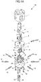
- Figure 1A shows an exploded drawing of an embodiment of the deflection module 100 according to the invention.
- the connecting lines 14 can be introduced into the lateral surface channels 60, 61, 62.
- the switching rotor is introduced into the connection stator 17 .
- the switching rotor consists of two parts. A first part 12 and a second part 13.
- a semicircular transport channel 30 was milled into both parts. After the assembly of the first part of the switching rotor 12 and the second part of the switching rotor 13, a transport channel 30 with a circular cross-section is formed at the contact level of the switching rotor parts.
- the first part of the switching rotor 12 and the second part of the switching rotor 13 are connected to one another by means of the adjusting pins 15, and corresponding bores are provided for this purpose.
- the transport channel connects a lateral surface channel 60, 61, 62 and thus the connecting line 14 introduced in the lateral surface channel to the base area channel 40.
- the base area channel 40 is arranged centrally in the base area 50 of the connecting stator 17 and can accommodate a connecting line 20.
- the switching rotor 12 & 13 also has 7 locking cylinders, which are arranged in the lateral surface of the switching rotor.
- the lock cylinders each consist of a cylinder element 11 that is rounded off on one side and a prestressed compression spring 10.
- the lock cylinders 10 & 11 are arranged in the switch rotor 12 & 13 in such a way that when the transport channel 30 of the switch rotor 12 & 13 faces a lateral surface channel 60, in each case one of the n-1 locking cylinders is exactly opposite a further lateral surface channel 61, 62 of the connecting stator 17 and closes it.
- the deflection module 100 thus enables the transport of a fluid or a droplet sequence from the base surface channel 40 through the transport channel 30 of the switching rotor 12 & 13 to exactly one lateral surface channel 60 and vice versa.
- the switching rotor 12 & 13 is positioned in its horizontal alignment with the aid of the stator cover 9 in the connection stator 17 .
- the radial alignment of the joined switching rotor 12 & 13 in the connection stator 17 is achieved by the precise insertion of the switching rotor in the cavity provided for it in the connection stator 17.
- the coupling ring 1 to the connection stator 17 all three components each have two bores for the two alignment pins 3 on.
- precisely fitting bores can be found in all three components (1, 9, 17).
- the connecting stator 17 and the stator cover 9 are fastened to the drive (stepper motor) via the coupling ring 1 using the assembly screws 19.
- Sealing between the stator cover 9 and the connecting stator 17 is effected, for example, by means of a radial shaft seal 7 .
- a radial shaft sealing ring cover 6 is applied to the stator cover 9 . This is attached to the stator cover 9 with screws.
- the shifting axle 4 with the axle coupling 2 is arranged on the radial shaft sealing ring cover 6 .
- the axle coupling 2 and thus the power transmission takes place via the shifting axle 4, which is connected to the axle coupling 2 with a coupling pin 5.
- the shifting axle 4 protrudes through a central hole in the radial shaft seal cover 6 and the stator cover 9 into the receptacle 70 in the shifting rotor 12 & 13.
- the shifting rotor is connected to the shifting axle 4 with the coupling pin 16.
- the switching rotor can be set in rotary motion by a stepping motor connected to the axle coupling.
- a coupling ring 1 ensures stable attachment with a defined distance between the drive and the deflection module 100 and is also fixed to the drive with the aid of the mounting screws 19 . Furthermore, the deflection module 100 has an adjustment screw 18 for setting the zero point and two ventilation connections to which the connection lines 21 and 8 can be connected.
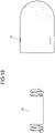
- Figure 1B 12 represents a lock cylinder which is formed from a cylinder element 11 and a compression spring 10.
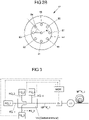
- Figure 2A shows a top view of a connection stator 17 shown schematically.
- the base surface channel 40 in the base surface 50 can be seen, as well as 8 lateral surface channels 60-67.
- the Figure 2A clarifies the definition of the angle ⁇ between adjacent lateral surface channels 60-67 and is shown as an example for the adjacent lateral surface channels 63 and 64.
- Figure 2B shows a plan view of a connection stator 17 shown schematically.
- the base channel 40 in the base 50 can be seen, as well as 8 base channels 80-87.
- the Figure 2B 8 illustrates the definition of the angle ⁇ between adjacent bottom channels 80-87 and is shown for the adjacent bottom channels 83 and 84 by way of example.
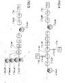
- Example 1 Generation of fluid sequences consisting of compartments embedded in one or more immiscible fluids with different concentrations of ingredients, such as cells
- the corresponding fluid channels KQ_1 to KQ_4 open into the device VA, designed as a gradient module, in the multi-fluid transport channel sections MFTK_1 of the multi-fluid transport channel MFTK and generate a fluid sequence.
- This passes through the detector D1, whose signals are evaluated by the measurement and control module MSM, which in turn controls the flow sources FQ_1 to FQ_4, thereby influencing the length and spacing of the compartments.
- the fluid sequence passes through the device VT into the multi-fluid transport channel section MFTK_2 of the multi-fluid transport channel MFTK, which is designed as a storage module (coil) and after being filled with the fluid sequence by means of the device VT is separated from the multi-fluid transport channel section MFTK_1 and, for example, stored in an incubator for cultivation.
- Detector D1 corresponds to the analysis module of the device according to the invention, the measuring and control module MSM to the control device.
- the deflection module (VSS) can be included, to which a number of memory modules are connected. The analysis of one or more compartments of a fluid sequence and/or complete fluid sequences and/or their phase boundaries is carried out with the detector D1.
- the corresponding fluid channels KQ_1 to KQ_5 open into the device VA, designed as a gradient module, into the multi-fluid transport channel sections MFTK_1 of the multi-fluid transport channel MFTK and generate a fluid sequence.
- the cell-free nutrient solution and the cell suspension for generating a gradient can be introduced, for example, via FQ_1 to FQ_3 via the associated channels KQ_1 to KQ_3.
- the introduction of the carrier fluid PFD through FQ_4 and FQ_5 into the inlet channels KQ_4 and KQ_5 leads to the formation of drops in the area where the two channels join the main channel.
- the fluid channels KQ_4 and KQ_5 are preferably arranged exactly opposite one another.
- a flow source FQ_1 transports a fluid into the multi-fluid transport channel section MFTK 2, which is designed as a storage module.
- the fluid displaces the fluid sequence located in the storage module, including the compartments located therein, and transports it via the devices VT_2, VA_2, VA_3 and VT_3 into the multi-fluid transport channel section MFTK_6, which is also designed as a storage module.
- the detectors D1 and D2 positioned between the devices VT_2 and VA_2 determine the number, the length and the distance between the compartments and the pressure in the multi-fluid transport channel MFTK, pass these parameters on to the measuring and control module MSM (in figure 4 not shown), which in turn controls the flow sources FQ_1 and FQ_2, the flow sink FS_3 and the controllable valves SVQ_2 and SVS_3 in such a way that the flow source FQ_2 flows a defined volume of fluid through the fluid transport channel KQ_2 and the controllable valve SVQ 2 into a region of the mouth of the fluid transport channel KQ_2 is transported into the multi-fluid transport channel MFTK compartment, this compartment is transported by the flow source FQ_1 to the mouth of the transport channel KS_3 in the multi-fluid transport channel MFTK and there the flow sink FS_3 through the controllable valve SVS_3 and the fluid transport channel KS_3 a defined fluid volume from the in the area of
- the device VA_3 is omitted and the fluid transport channels KQ_2 and KS_3 open into the multi-fluid transport channel MFTK in the device VA_2 and the fluid exchange takes place simultaneously.
- the deflection module according to the invention can be included, to which several storage modules are connected. This also applies to the alternative embodiment.
- the device VT_1 and/or VT_2 and/or VT_3 can be a deflection module according to the invention.
- the analysis for detecting optical and/or electrical and/or viscoelastic properties of one or more compartments of a fluid sequence and/or complete fluid sequences is carried out with the detector D1.
- Example 3 Addition of fluids, optionally including inorganic and/or organic material, to the compartments of fluid sequences
- a flow source FQ_1 transports a fluid into the multi-fluid transport channel section MFTK 2, which is designed as a storage module.
- the fluid displaces the fluid sequence located in the storage module, including the compartments located therein, and transports it via the devices VT_2, VA_2 and VT_3 into the multi-fluid transport channel section MFTK_6, which is also designed as a storage module.
- the detectors D1 and D2 positioned between the devices VT_2 and VA_2 determine the number, the length and the spacing of the compartments as well as the pressure in the multi-fluid transport channel MFTK, pass these parameters on to the measuring and control module MSM (in figure 4 not shown), which in turn controls the flow sources FQ_1 and FQ_2 as well as the controllable valve SVQ 2 in such a way that the flow source FQ_2 flows a defined volume of fluid through the fluid transport channel KQ_2 and the controllable valve SVQ 2 into a region where the fluid transport channel KQ_2 opens into the multi-fluid transport channel MFTK located compartment transported inside.
- MSM measuring and control module
- the deflection module according to the invention can be included, to which several storage modules are connected.
- the device VT_1 and/or VT_2 and/or VT_3 can therefore be a deflection module according to the invention.
- the analysis for detecting optical and/or electrical and/or viscoelastic properties of one or more compartments of a fluid sequence and/or complete fluid sequences is carried out with the detector D1.
- Example 4 Removal of fluids from compartments of fluid sequences, including any inorganic and/or organic material present there
- a flow source FQ_1 transports a fluid into the multi-fluid transport channel section MFTK 2, which is designed as a storage module.
- the fluid displaces the fluid sequence located in the storage module, including the compartments located therein, and transports it via the devices VT_2, VA_3 and VT_3 into the multi-fluid transport channel section MFTK_6, which is also designed as a storage module.
- the detectors D1 and D2 positioned between the devices VT_2 and VA_3 determine the number, the length and the distance between the compartments and the pressure in the multi-fluid transport channel MFTK, pass these parameters on to the measuring and control module MSM (in figure 4 not shown), which in turn controls the flow source FQ_1 and the flow sink FS_3 as well as the controllable valve SVS_3 in such a way that the flow sink FS_3 draws a defined volume of fluid through the fluid transport channel KS_3 and the controllable valve SVS_3 out of a volume in the area of the mouth of the fluid transport channel KS_3 into the multi-fluid transport channel MFTK located compartment transported out.
- MSM measuring and control module
- the deflection module according to the invention can be included, to which several storage modules are connected.
- the device VT_1 and/or VT_2 and/or VT_3 can therefore be a deflection module according to the invention.
- the analysis for detecting optical and/or electrical and/or viscoelastic properties of one or more compartments of a fluid sequence and/or complete fluid sequences is carried out with the detector D1.
- Example 5 Diverting one or more compartments of a fluid sequence and/or complete fluid sequences
- a flow source FQ_1 transports a fluid into the multi-fluid transport channel section MFTK 2, which is designed as a storage module.
- the fluid displaces the fluid sequence located in the storage module, including the compartments located therein, and transports it via the devices VT_2 and VSS, designed as a controllable switch (deflection module), into the multi-fluid transport channel section MFTK_4.
- MFTK_4 corresponds to the already described multi-fluid transport channel section (MFTK_Y) of the multi-fluid transport channel (MFTK) as a fluid sequence output.
- the fluid sequence or parts thereof or individual compartments can be transported into multi-fluid transport channel side sections MFTNK_1(...n), which can also be designed as a storage module.
- the detectors D1 and D2 determine the number, length and spacing of the compartments and the pressure in the multi-fluid transport channel MFTK, the sum of all MFTK_1 to MFTK_4 and MFTNK_1 to MFTNK_n, pass these parameters on to the measurement and control module MSM (in figure 5 not shown), which in turn controls the flow source FQ_1 and the controllable switch VSS in such a way that the complete fluid sequence or parts thereof or individual compartments are transported into the multi-fluid transport channel MFTK_4 and/or into one or more of the multi-fluid transport channel side sections MFTNK_1 to MFTNK_n.
- MFTK_3 corresponds to the already described multi-fluid transport channel section (MFTK_X) of the multi-fluid transport channel (MFTK) as a fluid sequence input.
- Example 6 Generation of fluid sequences using a double-lumen probe (two-fluid probe)
- the corresponding fluid channel KQ_1 opens into the device VA_1, which is designed as a two-fluid probe and which is immersed in the fluid to be compartmented, for example a cell suspension, which can be stirred or shaken for homogenization.
- the multi-fluid transport channel section MFTK_1 is connected to the flow sink FS_1 via the devices VT_1 and VT_2, the multi-fluid transport channel section MFTK_2 and the fluid channel KS_1 and also opens into the device VA_1.
- the signals of the detector D1 are used to characterize the Fluid sequence in MFTK_1 and are processed by the MSM, which in turn controls the flow rates of FQ_1 and FS_1, affecting the length and spacing of the compartments of the fluid sequence.
- the fluid sequence passes through the device VT_1 into the multi-fluid transport channel section MFTK_2, which is designed as a storage module and after being filled with the fluid sequence by means of the devices VT_1 and VT_2 is separated from the multi-fluid transport channel section MFTK_1 and from the fluid channel KS_1 and is stored in an incubator, for example, for cultivation.
- FIG. 6B shows the controllable drop generation with the double-lumen probe and integrated deflection module VSS.
- VSS deflection module
- the fluid sequence or parts thereof can be transported into multi-fluid transport channel side sections MFTNK_1-MFTNK_n, which can also be designed as a storage module.
- MFTNK_1-MFTNK_n which can also be designed as a storage module.
- These are connected to the devices VT_1 - VT_n and to VT_4 to VT_n+1, to which in turn flow sinks FS_1 - FS_n are connected.
- the storage modules By connecting the storage modules to the devices VT_1 to VT_n+1, they can each be separated from the deflection module and the respective FS, here FS_1 to FS_n, and stored in an incubator for cultivation, for example.
- Figure 6c shows the controllable drop generation using a double-lumen probe and two integrated deflection modules.
- two deflection modules only one flow sink FS_1 is required. Costs can be saved when using syringe pumps as flow sinks (e.g. with eight storage modules and only one deflection module, eight syringe pumps are required, with the use of two deflection modules only one syringe pump is required).
Landscapes
- Chemical & Material Sciences (AREA)
- General Engineering & Computer Science (AREA)
- Engineering & Computer Science (AREA)
- Health & Medical Sciences (AREA)
- Chemical Kinetics & Catalysis (AREA)
- Clinical Laboratory Science (AREA)
- Physics & Mathematics (AREA)
- Analytical Chemistry (AREA)
- Mechanical Engineering (AREA)
- Life Sciences & Earth Sciences (AREA)
- Biochemistry (AREA)
- General Health & Medical Sciences (AREA)
- General Physics & Mathematics (AREA)
- Immunology (AREA)
- Pathology (AREA)
- Fluid Mechanics (AREA)
- Apparatus Associated With Microorganisms And Enzymes (AREA)
- Measuring Fluid Pressure (AREA)
Applications Claiming Priority (1)
| Application Number | Priority Date | Filing Date | Title |
|---|---|---|---|
| DE102021116887.2A DE102021116887A1 (de) | 2021-06-30 | 2021-06-30 | Anordnung zum Generieren von Fluidsequenzen in einem Multifluidtransportkanal zum Konditionieren und Detektieren der in dem Multifluidtransportkanal generierten Fluidsequenzen |
Publications (2)
| Publication Number | Publication Date |
|---|---|
| EP4122604A2 true EP4122604A2 (fr) | 2023-01-25 |
| EP4122604A3 EP4122604A3 (fr) | 2023-04-05 |
Family
ID=82493997
Family Applications (1)
| Application Number | Title | Priority Date | Filing Date |
|---|---|---|---|
| EP22182285.1A Pending EP4122604A3 (fr) | 2021-06-30 | 2022-06-30 | Dispositif et procédé de génération des séquences de fluide dans un canal de transport de fluides multiples et de conditionnement et de détection des séquences de fluide générées dans le canal de transport de fluides multiples |
Country Status (2)
| Country | Link |
|---|---|
| EP (1) | EP4122604A3 (fr) |
| DE (1) | DE102021116887A1 (fr) |
Cited By (1)
| Publication number | Priority date | Publication date | Assignee | Title |
|---|---|---|---|---|
| WO2025021866A1 (fr) | 2023-07-26 | 2025-01-30 | Hochschule Aalen, Koerperschaft Des Oeffentlichen Rechts | Dispositif de transfert d'un échantillon liquide dans un système microfluidique |
Citations (5)
| Publication number | Priority date | Publication date | Assignee | Title |
|---|---|---|---|---|
| WO2007071374A1 (fr) | 2005-12-19 | 2007-06-28 | Institut für Bioprozess- und Analysenmesstechnik e.V. | Dispositif et procede de transport et de formation de compartiments |
| EP2156890A2 (fr) | 2008-08-21 | 2010-02-24 | INSTITUT FÜR BIOPROZESS- UND ANALYSENMESSTECHNIK e.V. | Agencement et procédé de production, de manipulation et d'analyse de compartiments |
| EP2248588A1 (fr) | 2009-05-08 | 2010-11-10 | Institut für Bioprozess- und Analysenmesstechnik e.V. | Système microfluidique pouvant être monté et démonté et procédé de noyage du système |
| DE102011088741A1 (de) | 2011-12-15 | 2013-06-20 | Institut für Bioprozess- und Analysenmesstechnik e.V. | Verfahren und Anordnung zum Markieren und Separieren von Zellen aus einer Zellsuspension |
| WO2020025679A1 (fr) | 2018-07-31 | 2020-02-06 | Institut Für Bioprozess- Und Analysenmesstechnik E. V. | Dispositif et procédé de caractérisation optique de fluides et/ou d'objets contenus dans les fluides dans des microcanaux |
Family Cites Families (4)
| Publication number | Priority date | Publication date | Assignee | Title |
|---|---|---|---|---|
| DE102009C (fr) | ||||
| DE1136169B (de) * | 1959-03-11 | 1962-09-06 | Ivan L Crawford | Mehrwegehahn |
| DK169928B1 (da) * | 1993-02-16 | 1995-04-03 | Verntofta Fjaederfae Ab | Fordelerventil til højtrykspumpe, især til sekvensvis fordeling af et trykmedie til flere forskellige udløb efter hinanden fra en og samme pumpe |
| JP6630566B2 (ja) * | 2012-07-05 | 2020-01-15 | メソ スケール テクノロジーズ エルエルシー | 分析評価カートリッジのバルブシステム |
-
2021
- 2021-06-30 DE DE102021116887.2A patent/DE102021116887A1/de active Pending
-
2022
- 2022-06-30 EP EP22182285.1A patent/EP4122604A3/fr active Pending
Patent Citations (5)
| Publication number | Priority date | Publication date | Assignee | Title |
|---|---|---|---|---|
| WO2007071374A1 (fr) | 2005-12-19 | 2007-06-28 | Institut für Bioprozess- und Analysenmesstechnik e.V. | Dispositif et procede de transport et de formation de compartiments |
| EP2156890A2 (fr) | 2008-08-21 | 2010-02-24 | INSTITUT FÜR BIOPROZESS- UND ANALYSENMESSTECHNIK e.V. | Agencement et procédé de production, de manipulation et d'analyse de compartiments |
| EP2248588A1 (fr) | 2009-05-08 | 2010-11-10 | Institut für Bioprozess- und Analysenmesstechnik e.V. | Système microfluidique pouvant être monté et démonté et procédé de noyage du système |
| DE102011088741A1 (de) | 2011-12-15 | 2013-06-20 | Institut für Bioprozess- und Analysenmesstechnik e.V. | Verfahren und Anordnung zum Markieren und Separieren von Zellen aus einer Zellsuspension |
| WO2020025679A1 (fr) | 2018-07-31 | 2020-02-06 | Institut Für Bioprozess- Und Analysenmesstechnik E. V. | Dispositif et procédé de caractérisation optique de fluides et/ou d'objets contenus dans les fluides dans des microcanaux |
Cited By (2)
| Publication number | Priority date | Publication date | Assignee | Title |
|---|---|---|---|---|
| WO2025021866A1 (fr) | 2023-07-26 | 2025-01-30 | Hochschule Aalen, Koerperschaft Des Oeffentlichen Rechts | Dispositif de transfert d'un échantillon liquide dans un système microfluidique |
| DE102023119806A1 (de) * | 2023-07-26 | 2025-01-30 | Hochschule Aalen, Körperschaft des öffentlichen Rechts | Vorrichtung zum Transfer einer Flüssigkeitsprobe innerhalb eines mikrofluidischen Systems |
Also Published As
| Publication number | Publication date |
|---|---|
| DE102021116887A1 (de) | 2023-01-05 |
| EP4122604A3 (fr) | 2023-04-05 |
Similar Documents
| Publication | Publication Date | Title |
|---|---|---|
| DE19928410C2 (de) | Gerätegehäuse mit einer Einrichtung zum Betrieb eines Labor-Mikrochips | |
| DE19928412C2 (de) | Versorgungselement für einen Labor-Mikrochip | |
| DE69303898T2 (de) | Fluessigkeitsbehandlung in mikrofabrizierten analytischen vorrichtungen | |
| DE19933458B4 (de) | Einrichtungen und Systeme zum Handhaben von Flüssigkeitsproben | |
| DE60119513T2 (de) | Vorrichtung und verfahren zum einspritzen von flüssigkeiten | |
| JP2008505345A (ja) | 分注システム、ソフトウェア、および関連する方法 | |
| DE102006030068A1 (de) | Vorrichtung und Verfahren zur Zu- und Abfuhr von Fluiden in geschüttelten Mikroreaktoren Arrays | |
| DE112018000184B4 (de) | Automatisierte Maschine zum Sortieren biologischer Flüssigkeiten | |
| WO2003056330A2 (fr) | Systeme de tri de cellules conçu pour trier ou separer des cellules en suspension dans un liquide en ecoulement en fonction de leur grandeur | |
| EP3347691B1 (fr) | Dispositif pour l'analyse de sang individualisée d'un patient et utilisation | |
| DE10213272A1 (de) | Vorrichtung und Verfahren zur Leitungsankopplung an fluidische Mikrosysteme | |
| LU102325B1 (de) | Probenbehältnis für eine Dispensiervorrichtung | |
| EP4334036A2 (fr) | Tête de dosage et système fluidique servant à la réception et au dosage d'au moins un milieu | |
| WO2020025679A1 (fr) | Dispositif et procédé de caractérisation optique de fluides et/ou d'objets contenus dans les fluides dans des microcanaux | |
| EP4122604A2 (fr) | Dispositif et procédé de génération des séquences de fluide dans un canal de transport de fluides multiples et de conditionnement et de détection des séquences de fluide générées dans le canal de transport de fluides multiples | |
| DE102008039117B3 (de) | Anordnung und Verfahren zum Erzeugen, Manipulieren und Analysieren von Kompartimenten | |
| EP1489404A1 (fr) | Méthode de production d'une cellule d'écoulement 3-D pour microscope | |
| EP1815230A1 (fr) | Systeme microfluidique comprenant un elargissement du canal | |
| WO2009152997A2 (fr) | Puce à blocage de flux | |
| WO2018011085A1 (fr) | Manipulation de liquides en utilisant un module fluidique présentant un plan fluidique incliné par rapport à un plan de rotation | |
| DE102018116918A1 (de) | Fluidik-Detektionssystem | |
| EP2440940B1 (fr) | Dispositif et procédé de formation et/ou d'agencement de successions d'un ou plusieurs échantillons de fluide dans un fluide porteur | |
| EP1397483B1 (fr) | Systeme microfluidique | |
| EP4429823B1 (fr) | Dispositif de manipulation et procédé de distribution d'objets | |
| DE102024114795A1 (de) | Kanalsystem für Mikrofluidikanwendungen und Mikrofluidikverfahren |
Legal Events
| Date | Code | Title | Description |
|---|---|---|---|
| PUAI | Public reference made under article 153(3) epc to a published international application that has entered the european phase |
Free format text: ORIGINAL CODE: 0009012 |
|
| STAA | Information on the status of an ep patent application or granted ep patent |
Free format text: STATUS: THE APPLICATION HAS BEEN PUBLISHED |
|
| AK | Designated contracting states |
Kind code of ref document: A2 Designated state(s): AL AT BE BG CH CY CZ DE DK EE ES FI FR GB GR HR HU IE IS IT LI LT LU LV MC MK MT NL NO PL PT RO RS SE SI SK SM TR |
|
| PUAL | Search report despatched |
Free format text: ORIGINAL CODE: 0009013 |
|
| AK | Designated contracting states |
Kind code of ref document: A3 Designated state(s): AL AT BE BG CH CY CZ DE DK EE ES FI FR GB GR HR HU IE IS IT LI LT LU LV MC MK MT NL NO PL PT RO RS SE SI SK SM TR |
|
| RIC1 | Information provided on ipc code assigned before grant |
Ipc: G01N 35/10 20060101ALI20230302BHEP Ipc: F16K 11/085 20060101ALI20230302BHEP Ipc: F16K 11/074 20060101ALI20230302BHEP Ipc: B01L 3/00 20060101ALI20230302BHEP Ipc: B01L 3/02 20060101AFI20230302BHEP |
|
| P01 | Opt-out of the competence of the unified patent court (upc) registered |
Effective date: 20230517 |
|
| STAA | Information on the status of an ep patent application or granted ep patent |
Free format text: STATUS: REQUEST FOR EXAMINATION WAS MADE |
|
| 17P | Request for examination filed |
Effective date: 20230928 |
|
| RBV | Designated contracting states (corrected) |
Designated state(s): AL AT BE BG CH CY CZ DE DK EE ES FI FR GB GR HR HU IE IS IT LI LT LU LV MC MK MT NL NO PL PT RO RS SE SI SK SM TR |
|
| STAA | Information on the status of an ep patent application or granted ep patent |
Free format text: STATUS: EXAMINATION IS IN PROGRESS |
|
| 17Q | First examination report despatched |
Effective date: 20251103 |