EP2248623B1 - Karosseriestruktur mit einer pressgehärteten B-Säule - Google Patents
Karosseriestruktur mit einer pressgehärteten B-Säule Download PDFInfo
- Publication number
- EP2248623B1 EP2248623B1 EP10003816.5A EP10003816A EP2248623B1 EP 2248623 B1 EP2248623 B1 EP 2248623B1 EP 10003816 A EP10003816 A EP 10003816A EP 2248623 B1 EP2248623 B1 EP 2248623B1
- Authority
- EP
- European Patent Office
- Prior art keywords
- press
- hardened
- pillar
- body structure
- region
- Prior art date
- Legal status (The legal status is an assumption and is not a legal conclusion. Google has not performed a legal analysis and makes no representation as to the accuracy of the status listed.)
- Active
Links
Images


Classifications
-
- B—PERFORMING OPERATIONS; TRANSPORTING
- B23—MACHINE TOOLS; METAL-WORKING NOT OTHERWISE PROVIDED FOR
- B23K—SOLDERING OR UNSOLDERING; WELDING; CLADDING OR PLATING BY SOLDERING OR WELDING; CUTTING BY APPLYING HEAT LOCALLY, e.g. FLAME CUTTING; WORKING BY LASER BEAM
- B23K11/00—Resistance welding; Severing by resistance heating
- B23K11/002—Resistance welding; Severing by resistance heating specially adapted for particular articles or work
-
- B—PERFORMING OPERATIONS; TRANSPORTING
- B21—MECHANICAL METAL-WORKING WITHOUT ESSENTIALLY REMOVING MATERIAL; PUNCHING METAL
- B21D—WORKING OR PROCESSING OF SHEET METAL OR METAL TUBES, RODS OR PROFILES WITHOUT ESSENTIALLY REMOVING MATERIAL; PUNCHING METAL
- B21D22/00—Shaping without cutting, by stamping, spinning, or deep-drawing
- B21D22/20—Deep-drawing
- B21D22/208—Deep-drawing by heating the blank or deep-drawing associated with heat treatment
-
- B—PERFORMING OPERATIONS; TRANSPORTING
- B23—MACHINE TOOLS; METAL-WORKING NOT OTHERWISE PROVIDED FOR
- B23K—SOLDERING OR UNSOLDERING; WELDING; CLADDING OR PLATING BY SOLDERING OR WELDING; CUTTING BY APPLYING HEAT LOCALLY, e.g. FLAME CUTTING; WORKING BY LASER BEAM
- B23K33/00—Specially-profiled edge portions of workpieces for making soldering or welding connections; Filling the seams formed thereby
- B23K33/004—Filling of continuous seams
- B23K33/008—Filling of continuous seams for automotive applications
-
- C—CHEMISTRY; METALLURGY
- C21—METALLURGY OF IRON
- C21D—MODIFYING THE PHYSICAL STRUCTURE OF FERROUS METALS; GENERAL DEVICES FOR HEAT TREATMENT OF FERROUS OR NON-FERROUS METALS OR ALLOYS; MAKING METAL MALLEABLE, e.g. BY DECARBURISATION OR TEMPERING
- C21D9/00—Heat treatment, e.g. annealing, hardening, quenching or tempering, adapted for particular articles; Furnaces therefor
- C21D9/18—Heat treatment, e.g. annealing, hardening, quenching or tempering, adapted for particular articles; Furnaces therefor for knives, scythes, scissors, or like hand cutting tools
-
- C—CHEMISTRY; METALLURGY
- C21—METALLURGY OF IRON
- C21D—MODIFYING THE PHYSICAL STRUCTURE OF FERROUS METALS; GENERAL DEVICES FOR HEAT TREATMENT OF FERROUS OR NON-FERROUS METALS OR ALLOYS; MAKING METAL MALLEABLE, e.g. BY DECARBURISATION OR TEMPERING
- C21D9/00—Heat treatment, e.g. annealing, hardening, quenching or tempering, adapted for particular articles; Furnaces therefor
- C21D9/46—Heat treatment, e.g. annealing, hardening, quenching or tempering, adapted for particular articles; Furnaces therefor for sheet metals
-
- B—PERFORMING OPERATIONS; TRANSPORTING
- B23—MACHINE TOOLS; METAL-WORKING NOT OTHERWISE PROVIDED FOR
- B23K—SOLDERING OR UNSOLDERING; WELDING; CLADDING OR PLATING BY SOLDERING OR WELDING; CUTTING BY APPLYING HEAT LOCALLY, e.g. FLAME CUTTING; WORKING BY LASER BEAM
- B23K2101/00—Articles made by soldering, welding or cutting
- B23K2101/006—Vehicles
Definitions
- the invention relates to a method for producing a parts composite with at least one press-hardened sheet-metal component for a motor vehicle.
- the invention further relates to a motor vehicle comprising such a composite part, and a body structure for a motor vehicle.
- Press-hardened sheet-metal components as well as methods and apparatus for their production, are known from the prior art. This is represented on the representative DE 10 2007 040 013 A1 and DE 10 2007 040 028 A1 the same applicant.
- press-hardening the strength and / or hardness of a sheet material is increased by a heat treatment and final cooling in a forming tool.
- the increase in strength and / or hardness (hardening) of the sheet material is based essentially on a structural transformation.
- Press-hardened sheet-metal components in addition to their high strengths and / or hardnesses, also have a high energy absorption capacity up to failure (fracture), which is why such press-hardened sheet-metal components are preferably also used in motor vehicle construction.
- a body structure for a passenger car, comprising a press-hardened B-pillar is known from DE 103 23 746 known.
- a region with a lower strength and / or hardness is a region or section of the press-hardened sheet-metal component that is essentially spatially and / or substantially exactly defined, which is indicated by the term "local". This area preferably surrounds the welded connection.
- the "other areas" of the press-hardened sheet metal component are the remaining areas that are characterized by a high strength and / or hardness due to the press hardening. It is preferably provided that the other regions of the press-hardened sheet-metal component essentially have a uniform strength and / or hardness.
- a common sheet material has e.g. a strength (tensile strength) of about 400 MPa before press-hardening and a strength of about 1200 to 1600 MPa after press-hardening.
- the "second component” must be a metal component in terms of weldability. It is preferably provided that this is a sheet metal component. This may also be a press-hardened sheet metal component, which then preferably also has areas with a lower strength and / or hardness.
- “Strength” is understood to mean a material property of the sheet material which describes the mechanical resistance which the material of the sheet material brings about for plastic deformation or also for a separation.
- “Hardness” is understood to mean a material property which describes the mechanical resistance which the material of the sheet metal material opposes to an external mechanical action. Strength and hardness can be correlated according to common material models.
- a “mechanical load” is understood to mean a one-dimensional or multidimensional load state to which the press-hardened sheet-metal component is exposed, in particular in the region of a welded connection.
- a highly dynamic load refers to sudden or rapidly changing load conditions, especially with high amounts.
- the invention is based on the recognition that the cause of the crack formation in the region of a welded joint is the heat input during the welding process. Because of this heat input, in a heat affected zone around the weld joint, at least partial transformation and / or reconversion of the hard structure due to press hardening into a structure having lower strength and / or hardness, which may be referred to as a "soft region". At a greater distance to the weld, however, the hard structure of the sheet metal component, as obtained by the press-hardening, remains unaffected. At a spot weld, this soft region is e.g. formed annularly around the welding point, with a ring width of about 0.5 to 1.0 mm. In contrast, the weld point located centrally in this soft region again has a high strength and / or hardness, which often still lies above that of the press-hardened sheet metal material. The same applies mutatis mutandis to a weld.
- a body structure is understood to mean the load-bearing structure of the vehicle body of a motor vehicle, which as a rule is formed from sheet-metal components joined together. This is where the body attachment parts are fastened, including, for example, the vehicle doors, the boot lid and the front door.
- the Vehicle body is therefore the entirety of body structure and body suspension parts. Under a chassis, the totality of those parts understood that serve the connection of the vehicle body to the road. These include in particular steering parts and suspension parts.
- the body structure comprises a press-hardened B-pillar.
- the press-hardened B-pillar is formed from a 22MnB5 steel.
- the press-hardened B-pillar may also be formed of a 16MnB5 steel.
- the second component of the parts composite can also be formed from this steel material.
- the welded connection is a welding point. This does not exclude the presence of welds.
- the area with the lower strength and / or hardness corresponds to a surface area which corresponds to at least 15 times, preferably at least 10 times and in particular at least 5 times the spot area, the spot being preferred is arranged substantially in the centroid, in particular in the geometric centroid, this surface area. This surface area is determined from the plan view in the direction of the spot weld.
- a weld point in the plan view has a diameter of 5 mm, which corresponds to a spot weld area of approximately 20 mm 2
- the surface area surrounding this weld point with the lower strength and / or hardness has a surface area of at least 300 mm 2 , preferably at least 200 mm 2 and in particular of at least 100 mm 2 .
- Common spot diameter in automotive engineering and in particular in the body shop are 3 to 8 mm.
- the welded joint is a weld. This does not exclude the presence of one or more welds.
- the area with the lower strength and / or hardness corresponds to a surface area extending longitudinally to the weld seam, wherein the width of this area at least 10 times, preferably at least 5 times and in particular at least 2.5 times the weld width and wherein the weld extends substantially in the middle of this surface area.
- This area is determined from the top view in the direction of the weld. For example, if a weld has a width of 2 mm, then the width of the surface area surrounding this weld with the lower strength and / or hardness, which is transverse to the weld seam, is 20 mm, preferably 10 mm and in particular 5 mm.
- Common weld widths in the automotive industry and in particular in the body shop are 0.7 to 3 mm.
- Common weld lengths are in the range of 20 to 30 mm.
- the area of lower strength and / or hardness also surrounds the end points of the weld.
- Fig. 1 shows a method for producing a parts composite 10 in a schematic overview.
- step I a press-hardened sheet-metal component 20 having a joining flange 21 is produced.
- step II this becomes press-hardened sheet-metal component 20 welded along its joining flange 21 with a second component 30 to form the parts composite 10, wherein the welding is carried out by means of a plurality of welds 40.
- the press-hardened sheet metal component 20 and the second component 30 are each formed from a sheet metal material.
- Fig. 2a shows in a plan view of a welding point 40, which connects the press-hardened sheet metal component 20 along its joining flange 21 with the second component 30, to which the second component 30 also includes a joint flange 31.
- the press-hardened sheet-metal component 20 has a substantially constant strength and / or hardness in all regions, ie also in the joining flange 21, as it sets during the press-hardening process in step I.
- step II As a result of the heat input at the joining flange 21 of the press-hardened sheet metal component 20 around the welding point 40 around an annular region 22 forms within which the strength and / or hardness of the sheet material below that in other areas of the press-hardened sheet metal component 20.
- the heat input during the welding operation causes within this region 22 at least partially a conversion and / or back conversion of the hardened during the press hardening process to a structure with less solid and / or less hard properties.
- This area 22 can thus also be referred to as a soft area. This affects only the press-hardened sheet metal component 20, unless the sheet material of the second component 30 in turn does not respond to the heat input during the welding process.
- the annular soft area 22 also shows the sectional view of Fig. 2b ,
- the annular, soft region 22 causes mechanical stress on the sheet metal component 20 in the region of the welding point 40 a notch effect, due to which occur in the sheet material stress peaks that can lead to crack initiation in this area 22 and in particular at the edge points.
- crack propagation may also occur in the hard areas of the hard area adjacent to the soft area 22 Sheet metal component 20 come, which can eventually lead to failure of the sheet metal component 20 by breakage. This is undesirable and extremely critical especially with regard to a safety-relevant use of such press-hardened sheet-metal components.
- step I in producing the press-hardened sheet metal component 20 in the region of the welding point 40, i. in the region of the joining flange 21, locally a lower strength and / or hardness is formed or that in the press hardening a microstructure transformation in this area is prevented.
- the joining flange 21 of the press-hardened sheet metal component 20 is formed here overall, ie over its entire width (as shown) with a lower strength and / or hardness, which is represented by the hatching 23.
- the strength and / or hardness corresponds, for example, to the strength and / or hardness of the sheet material prior to press hardening or may also be higher. This has, on the one hand, the result that the heat input during the welding process can not bring about a reconversion of the microstructure in the area of welding point 40 and, secondly, that a notch effect in the region of the welding point 40 is absent or at least markedly reduced under mechanical stress.
- the joint flange 21 has an overall lower strength and / or hardness compared to the other, press-hardened areas, the load capacity of the press-hardened sheet metal component 20 increases, in particular in the case of a highly dynamic stress in the area of the weld point 40, since crack initiation does not occur, as a result of which the applied mechanical energy (Up to a certain maximum) can be fully implemented in a deformation work on the sheet metal component 20, without this comes to the failure of the sheet metal component 20 by breakage.
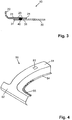
- Fig. 4 shows the foot region of a press-hardened B-pillar 50 (strictly speaking, it is an internal reinforcing member for a B-pillar), which in a Body structure is integrated for a motor vehicle.
- the B pillar 50 comprises a longitudinal profile section 51, which merges into a transverse profile section 52 in the lower region.
- the reference numeral 53 denotes a lower door hinge connection.
- 54 designates a joining flange or mounting flange by means of which the B pillar 50 can be integrated into the body structure, for which purpose at least one welded joint is arranged along this joining flange 54, in the form of a plurality of welding points and / or at least one weld seam.
- the reference numeral 55 denotes a portion of the joining flange 54, which extends approximately from the lower door hinge connection 53 to the outlet of the component curvature at the transition between the longitudinal profile section 51 and the cross-sectional section 52. It has been found that with a mechanical loading of the B-pillar 50, in particular with a highly dynamic load such as, for example, in a side impact, a weld in this section 55 is particularly critical to crack initiation. This is e.g. attributed to the fact that a concomitant with a side impact inflection of the longitudinal profile section 51 has a strong tensile load in this section 55 of the joint flange 54 result.
- this critical section 55 of the joining flange 54 is already formed from the press-hardening process with a lower strength and / or hardness than the other sections of the press-hardened B-pillar 50.
- preferred possibilities for producing such a B-pillar are described. Pillar shown.
- Fig. 5 shows a press hardening tool 60 for the production of the B-pillar 50 from the Fig. 4 in a partial section, which includes the critical portion 55 of the joint flange 54.
- the press hardening tool 60 is formed of a lower die 61 and an upper die 62. Alternatively, the press hardening tool 60 may also be constructed in several parts. Not shown are any cooling devices within the pressing tool 60, which is referenced representative of the above-mentioned prior art.
- an insert 63 is arranged in the upper tool 62.
- the insert 63 extends along the in Fig. 4 hatched shown critical portion 55 of the joint flange 54, which is apparent from the Fig. 5 is not apparent.
- This insert 63 may for example be formed of a material which has a different heat capacity and / or heat conduction with respect to the tool material, such as a ceramic material, whereby a slower cooling of the critical portion 55 of the joining flange 54 relative to the other regions of the B-pillar 50 achieved and eg a structural transformation is prevented.
- the insert 63 is here arranged such that at the B-pillar 50 the transition radius R to the critical portion 55 of the joining flange 54 is still included in the press hardening. Alternatively and / or additionally, the insert 63 can also be arranged in the lower tool 61. The insert 63 need not reach the outer edge of the press hardening tool 60, as shown.
- the insert 63 may also be an actively heatable heating element, by means of which the cooling in the critical section 55 of the joining flange 54 can be influenced directly.
- this heating element can be coupled to a control unit.
- a heating device can also be installed directly in the upper tool 62 and / or lower tool 61.
- Fig. 6 shows an alternative embodiment of a press hardening tool 60a for making the B-pillar 50 of FIG Fig. 4
- the structure of the press-hardening tool 60a substantially corresponds to the structure of the press-hardening tool 60 of FIG Fig. 5
- a recess or an air gap 64a is provided in the upper tool 62a, which causes a slower cooling of the critical portion 55 of the Fügeflansches 54, with respect to the other on the lower tool 61a and the upper tool 62a adjacent areas of the B-pillar during press hardening process 50.
- the air gap 64a may alternatively and / or additionally also be arranged in the lower tool 61a. Furthermore, the Air gap 64 a also be led to the outer edge of the press hardening tool 60 a, as in Fig. 5 shown insert 63.
Landscapes
- Engineering & Computer Science (AREA)
- Chemical & Material Sciences (AREA)
- Mechanical Engineering (AREA)
- Physics & Mathematics (AREA)
- Thermal Sciences (AREA)
- Crystallography & Structural Chemistry (AREA)
- Materials Engineering (AREA)
- Metallurgy (AREA)
- Organic Chemistry (AREA)
- Body Structure For Vehicles (AREA)
Description
- Die Erfindung betrifft ein Verfahren zur Herstellung eines Teileverbunds mit wenigstens einem pressgehärteten Blechbauteil für ein Kraftfahrzeug. Die Erfindung betrifft ferner ein Kraftfahrzeug umfassend einen solchen Teileverbund, sowie eine Karosseriestruktur für ein Kraftfahrzeug.
- Pressgehärtete Blechbauteile, sowie Verfahren und Vorrichtung zu deren Herstellung, sind aus dem Stand der Technik bekannt. Hierzu wird stellvertretend auf die
DE 10 2007 040 013 A1 undDE 10 2007 040 028 A1 derselben Anmelderin verwiesen. Beim Presshärten wird die Festigkeit und/oder Härte eines Blechmaterials durch eine Wärmebehandlung und abschließende Abkühlung in einem Umformwerkzeug heraufgesetzt. Die Festigkeitserhöhung und/oder Härteerhöhung (Härtung) des Blechmaterials basiert im Wesentlichen auf einer Gefügeumwandlung. Pressgehärtete Blechbauteile weisen neben ihren hohen Festigkeiten und/oder Härten auch ein hohes Energieaufnahmevermögen bis zum Versagen (Bruch) auf, weshalb solche pressgehärteten Blechbauteile bevorzugt auch im Kraftfahrzeugbau zum Einsatz kommen. Eine Karosseriestruktur für einen Personenkraftwagen, umfassend eine pressgehärtete B-Säule, ist aus derDE 103 23 746 bekannt. - Im Kraftfahrzeugbau erfolgt das Fügen pressgehärteter Blechbauteile mit anderen Bauteilen oder deren Einbindung in eine übergeordnete Struktur, wie z.B. in eine Karosseriestruktur, zumeist mittels von Schweißverbindungen. In der Praxis besteht jedoch das Problem, dass sich bei einer starken mechanischen Belastung eines pressgehärteten Blechbauteils und insbesondere bei einer hochdynamischen Beanspruchung während eines Unfalls (Crash), ausgehend von einer solchen Schweißverbindung Risse im pressgehärteten Blechbauteil ausbilden, die zum vorzeitigen Versagen dieses Blechbauteils führen.
- Es ist daher die Aufgabe der vorliegenden Erfindung, Möglichkeiten zur Vermeidung einer solchen Rissausbildung aufzuzeigen.
- Diese Aufgabe wird gelöst von einer Karosseriestruktur mit den Merkmalen des Anspruchs 1. Die abhängigen Ansprüche betreffen vorteilhafte und bevorzugte Weiterbildungen.
- Bei einem Bereich mit einer geringeren Festigkeit und/oder Härte handelt es sich um einen räumlich und/oder flächenmäßig im Wesentlichen exakt definierten Bereich bzw. Abschnitt des pressgehärteten Blechbauteils, was durch die Bezeichnung "lokal" angezeigt ist. Bevorzugt umgibt dieser Bereich die Schweißverbindung.
- Die "anderen Bereiche" des pressgehärteten Blechbauteils sind die übrigen Bereiche, die infolge der Presshärtung durch eine hohe Festigkeit und/oder Härte gekennzeichnet sind. Bevorzugt ist vorgesehen, dass die anderen Bereiche des pressgehärteten Blechbauteils im Wesentlichen eine einheitliche Festigkeit und/oder Härte aufweisen. Ein gängiges Blechmaterial weist z.B. vor dem Presshärten eine Festigkeit (Zugfestigkeit) von ca. 400 MPa und nach dem Presshärten eine Festigkeit von ca. 1200 bis 1600 MPa auf.
- Das "zweite Bauteil" muss im Hinblick auf die Schweißbarkeit ein Metallbauteil sein. Bevorzugt ist vorgesehen, dass es sich hierbei um ein Blechbauteil handelt. Dies kann auch ein pressgehärtetes Blechbauteil sein, dass dann bevorzugt ebenfalls Bereiche mit einer geringeren Festigkeit und/oder Härte aufweist.
- Unter "Festigkeit" wird eine Werkstoffeigenschaft des Blechmaterials verstanden, welche den mechanischen Widerstand beschreibt, den der Werkstoff des Blechmaterials einer plastischen Verformung oder auch einer Trennung entgegenbringt. Unter "Härte" wird eine Werkstoffeigenschaft verstanden, welche den mechanischen Widerstand beschreibt, den der Werkstoff des Blechmaterials einer äußeren mechanischen Einwirkung entgegensetzt. Festigkeit und Härte können nach gängigen Werkstoffmodellen korrelieren.
- Unter einer "mechanisches Belastung" wird ein eindimensionaler oder mehrdimensionaler Lastzustand verstanden, dem das pressgehärtete Blechbauteil insbesondere im Bereich einer Schweißverbindung ausgesetzt ist. Eine hochdynamische Beanspruchung bezeichnet schlagartig auftretende oder sich schnell ändernde Lastzustände, insbesondere mit hohen Beträgen.
- Die Erfindung basiert auf der Erkenntnis, dass die Ursache für die Rissausbildung im Bereich einer Schweißverbindung die Wärmeeinbringung während des Schweißvorgangs ist. Aufgrund dieser Wärmeeinbringung erfolgt in einer Wärmeeinflusszone um die Schweißverbindung herum eine zumindest teilweise Umwandlung und/oder Rückumwandlung des infolge der Presshärtung harten Gefüges in ein Gefüge mit einer geringeren Festigkeit und/oder Härte, was als "weicher Bereich" bezeichnet werden kann. In größerer Entfernung zur Schweißverbindung bleibt hingegen das harte Gefüge des Blechbauteils, wie dies durch die Presshärtung erhalten wird, unbeeinflusst. Bei einem Schweißpunkt ist dieser weiche Bereich z.B. kreisringförmig um den Schweißpunkt herum ausgebildet, mit einer Ringbreite von in etwa 0,5 bis 1,0 mm. Demgegenüber weist der zentral in diesem weichen Bereich befindliche Schweißpunkt wiederum eine hohe Festigkeit und/oder Härte auf, die häufig noch oberhalb derer des pressgehärteten Blechmaterials liegt. Ähnliches gilt sinngemäß für eine Schweißnaht.
- Somit sind in einem relativ kleinen Flächenbereich (bezüglich der Draufsicht) hohe Festigkeits- und/oder Härtedifferenzen gegeben. Insbesondere an den Übergängen zum weichen Bereich besteht ein deutlicher Festigkeits- bzw. Härteabfall, der bei mechanischer Belastung eine Kerbwirkung hervorruft. Aufgrund dieser Kerbwirkung kommt es insbesondere bei hochdynamischer Beanspruchung des pressgehärteten Blechbauteils im Bereich der Schweißverbindung zu Spannungsspitzen im Blechmaterial, die lokal höhe plastische Dehnungen des Blechmaterials hervorrufen und somit eine Rissinitiierung bewirken können. Ein initiierter Riss kann sich dann in angrenzende Blechbauteilbereiche mit festem bzw. hartem Gefüge ausbreiten, was schließlich zum Bruch des pressgehärteten Blechbauteils führt. Die unerwünschte Rissausbildung erfolgt demnach durch den Mechanismus einer Rissinitiierung im Bereich der Schweißverbindung und einer sich hieran anschließenden Rissausbreitung, was erfindungsgemäß verhindert wird.
- Unter einer Karosseriestruktur wird der tragende Aufbau der Fahrzeugkarosserie eines Kraftfahrzeugs verstanden, der in der Regel aus miteinander gefügten Blechbauteilen gebildet ist. Hieran werden die Karosserieanhängteile befestigt, wozu z.B. die Fahrzeugtüren, der Heckdeckel und die Frontklappe zählen. Die Fahrzeugkarosserie ist demnach die Gesamtheit aus Karosseriestruktur und Karosserieanhängteilen. Unter einem Fahrwerk wird die Gesamtheit jener Teile verstanden, die der Verbindung der Fahrzeugkarosserie zur Fahrbahn dienen. Hierzu zählen insbesondere Lenkungsteile und Radaufhängungsteile.
- Gemäß der Erfindung weist die Karosseriestruktur eine Pressgehärtete B-Säule auf.
- Gemäß einer bevorzugten Weiterbildung ist vorgesehen, dass die pressgehärtete B-Säule aus einem 22MnB5-Stahl gebildet ist. Alternativ kann die pressgehärtete B-Säule auch aus einem 16MnB5-Stahl gebildet sein. Das zweite Bauteil des Teileverbunds kann ebenfalls aus diesem Stahlwerkstoff gebildet sein.
- Gemäß einer bevorzugten Weiterbildung ist vorgesehen, dass die Schweißverbindung ein Schweißpunkt ist. Dies schließt das Vorhandensein von Schweißnähten nicht aus.
- Gemäß einer bevorzugten Weiterbildung ist vorgesehen, dass der Bereich mit der geringeren Festigkeit und/oder Härte einem Flächenbereich entspricht, der wenigstens dem 15-fachen, bevorzugt wenigstens dem 10-fachen und insbesondere wenigstens dem 5-fachen der Schweißpunktfläche entspricht, wobei der Schweißpunkt bevorzugt im Wesentlichen im Flächenschwerpunkt, insbesondere im geometrischer Flächenschwerpunkt, dieses Flächenbereichs angeordnet ist. Dieser Flächenbereich ist aus der Draufsicht in Richtung des Schweißpunkts bestimmt. Hat ein Schweißpunkt in der Draufsicht z.B. einen Durchmesser von 5 mm, was einer Schweißpunktfläche von ca. 20 mm2 entspricht, so hat der diesen Schweißpunkt umgebende Flächenbereich mit der geringeren Festigkeit und/oder Härte eine Flächengröße von wenigstens 300 mm2, bevorzugt von wenigstens 200 mm2 und insbesondere von wenigstens 100 mm2. Gängige Schweißpunktdurchmesser im Kraftfahrzeugbau und insbesondere im Karosseriebau sind 3 bis 8 mm.
- Gemäß einer bevorzugten Weiterbildung ist vorgesehen, dass die Schweißverbindung eine Schweißnaht ist. Dies schließt das Vorhandensein eines oder mehrerer Schweißpunkte nicht aus.
- Gemäß einer bevorzugten Weiterbildung ist vorgesehen, dass der Bereich mit der geringeren Festigkeit und/oder Härte einem Flächenbereich entspricht, der sich längs zum Schweißnahtverlauf erstreckt, wobei die Breite dieses Bereichs wenigstens dem 10-fachen, bevorzugt wenigstens dem 5-fachen und insbesondere wenigstens dem 2,5-fachen der Schweißnahtbreite entspricht und wobei die Schweißnaht im wesentlichen mittig dieses Flächenbereichs verläuft. Dieser Flächenbereich ist aus der Draufsicht in Richtung der Schweißnaht bestimmt. Hat eine Schweißnaht z.B. eine Breite von 2 mm, so beträgt die quer zum Schweißnahtverlauf bemessene Breite des diese Schweißnaht umgebenden Flächenbereichs mit der geringeren Festigkeit und/oder Härte 20 mm, bevorzugt 10 mm und insbesondere 5 mm. Gängige Schweißnahbreiten im Kraftfahrzeugbau und insbesondere im Karosseriebau sind 0,7 bis 3 mm. Gängige Schweißnahtlängen liegen im Bereich von 20 bis 30 mm. Der Bereich mit der geringeren Festigkeit und/oder Härte umgibt auch die Endpunkte der Schweißnaht.
- Nachfolgend wird die Erfindung beispielhaft anhand der Figuren näher erläutert. Es zeigen:
- Fig. 1
- das Verfahren zum Herstellen eines Teileverbunds in einer schematischen Übersicht;
- Fig. 2
- eine Punktschweißverbindung nach dem Stand der Technik zwischen einem pressgehärteten Blechbauteil und einem zweiten Bauteil, in einer schematischen Draufsicht und in einer Schnittansicht;
- Fig. 3
- eine Punktschweißverbindung zwischen einem pressgehärteten Blechbauteil und einem zweiten Bauteil, in einer schematischen Schnittansicht, entsprechend zur
Fig. 2 ; - Fig. 4
- eine pressgehärtete B-Säule einer Kraftfahrzeugkarosserie, deren Fügeflansch abschnittsweise eine geringere Festigkeit und/oder Härte aufweist, in einer perspektivischen Ansicht;
- Fig. 5
- einen Ausschnitt aus einem Presshärtwerkzeug zum Herstellen der B-Säule aus
Fig. 4 , in einer schematischen Schnittansicht; und - Fig. 6
- eine alternative Ausführungsform des Presshärtewerkzeugs aus
Fig. 5 . -
Fig. 1 zeigt ein Verfahren zur Herstellung eines Teileverbunds 10 in einer schematischen Übersicht. Im Schritt I wird ein pressgehärtetes Blechbauteil 20 hergestellt, das einen Fügeflansch 21 aufweist. Im Schritt II wird dieses pressgehärtete Blechbauteil 20 entlang seines Fügeflansches 21 mit einem zweiten Bauteil 30 zur Bildung des Teileverbunds 10 verschweißt, wobei die Verschweißung mittels einer Vielzahl von Schweißpunkten 40 erfolgt. Das pressgehärtete Blechbauteil 20 und das zweite Bauteil 30 sind jeweils aus einem Blechmaterial gebildet. -
Fig. 2a zeigt in einer Draufsicht einen Schweißpunkt 40, der das pressgehärtete Blechbauteil 20 entlang seines Fügeflansches 21 mit dem zweiten Bauteil 30 verbindet bzw. fügt, wozu das zweite Bauteil 30 ebenfalls einen Fügeflansch 31 umfasst. Gemäß dem Stand der Technik weist das pressgehärtete Blechbauteil 20 in allen Bereichen, d.h. auch im Fügeflansch 21, eine im Wesentlichen konstante Festigkeit und/oder Härte auf, wie sich diese während des Presshärtevorgangs im Schritt I einstellt. - Während des Schweißvorgangs im Schritt II bildet sich infolge der Wärmeeinbringung am Fügeflansch 21 des pressgehärteten Blechbauteils 20 um den Schweißpunkt 40 herum ein kreisringförmiger Bereich 22 aus, innerhalb dem die Festigkeit und/oder Härte des Blechmaterials unterhalb derer in anderen Bereichen des pressgehärteten Blechbauteils 20 liegt. Die Wärmeeinbringung beim Schweißvorgang bewirkt innerhalb dieses Bereichs 22 zumindest teilweise eine Umwandlung und/oder Rückumwandlung des beim Presshärtevorgang gehärteten Gefüges hin zu einem Gefüge mit weniger festen und/oder weniger harten Eigenschaften. Dieser Bereich 22 kann somit auch als weicher Bereich bezeichnet werden. Hiervon betroffen ist lediglich das pressgehärtete Blechbauteil 20, sofern das Blechmaterial des zweiten Bauteils 30 seinerseits nicht auf die Wärmeeinbringung während des Schweißvorgangs reagiert. Den kreisringförmigen, weichen Bereich 22 zeigt auch die Schnittansicht der
Fig. 2b . - Der kreisringförmige, weiche Bereich 22 ruft bei mechanischer Belastung des Blechbauteils 20 im Bereich des Schweißpunkts 40 eine Kerbwirkung hervor, aufgrund derer im Blechmaterial Spannungsspitzen auftreten, die zu einer Rissinitiierung in diesem Bereich 22 und insbesondere an dessen Randstellen führen können. Ausgehend von dieser Rissinitiierung kann es zu einer Rissausbreitung auch in die an den weichen Bereich 22 angrenzenden harten Bereiche des Blechbauteils 20 kommen, was schließlich zum Versagen des Blechbauteils 20 durch Bruch führen kann. Dies ist unerwünscht und insbesondere auch im Hinblick auf einen sicherheitsrelevanten Einsatz solcher pressgehärteter Blechbauteile äußerst kritisch.
- Es wird daher vorgeschlagen, dass im Schritt I beim Herstellen des pressgehärteten Blechbauteils 20 im Bereich des Schweißpunktes 40, d.h. im Bereich des Fügeflansches 21, lokal eine geringere Festigkeit und/oder Härte ausgebildet wird oder dass beim Presshärten eine Gefügeumwandlung in diesem Bereich verhindert wird.
- Dies zeigt
Fig. 3 . Der Fügeflansch 21 des pressgehärteten Blechbauteils 20 ist hier im Gesamten, d.h. über seine gesamte Breite (gemäß Darstellung) mit einer geringeren Festigkeit und/oder Härte ausgebildet, was durch die Schraffur 23 dargestellt ist. Die Festigkeit und/oder Härte entspricht z.B. der Festigkeit und/oder Härte des Blechmaterials vor dem Presshärten oder kann auch darüber liegen. Dies hat zum einen zur Folge, dass die Wärmeeinbringung beim Schweißvorgang keine Rückumwandlung des Gefüges im Bereich Schweißpunkts 40 bewirken kann und dass zum anderen bei mechanischer Belastung eine Kerbwirkung im Bereich des Schweißpunkts 40 ausbleibt oder zumindest deutlich verringert wird. - Obwohl der Fügeflansch 21 eine im Gesamten geringere Festigkeit und/oder Härte gegenüber den anderen, pressgehärteten Bereichen aufweist, steigt insbesondere bei einer hochdynamischen Beanspruchung im Bereich des Schweißpunkts 40 die Belastbarkeit des pressgehärteten Blechbauteils 20 an, da eine Rissinitiierung ausbleibt, wodurch die aufgebrachte mechanische Energie (bis zu einem bestimmten Höchstmaß) vollständig in eine Formänderungsarbeit am Blechbauteil 20 umgesetzt werden kann, ohne dass es hierbei zum Versagen des Blechbauteils 20 durch Bruch kommt.
-
Fig. 4 zeigt den Fußbereich einer pressgehärteten B-Säule 50 (genau genommen handelt es sich um ein Innenverstärkungsteil für eine B-Säule), die in eine Karosseriestruktur für ein Kraftfahrzeug eingebunden wird. Die B-Säule 50 umfasst einen Längsprofilabschnitt 51 der im unteren Bereich in einen Querprofilabschnitt 52 übergeht. Das Bezugszeichen 53 bezeichnet eine untere Türscharnieranbindung. Mit 54 ist ein Fügeflansch bzw. Befestigungsflansch bezeichnet, mittels dem die B-Säule 50 in die Karosseriestruktur eingebunden werden kann, wozu entlang dieses Fügeflansches 54 wenigstens eine Schweißverbindung angeordnet wird, im Form mehrerer Schweißpunkte und/oder wenigstens einer Schweißnaht. - Das Bezugszeichen 55 bezeichnet einen Abschnitt des Fügeflansches 54, der sich in etwa von der unteren Türscharnieranbindung 53 bis zum Auslauf der Bauteilkrümmung am Übergang zwischen Längsprofilabschnitt 51 und Querprofilabschnitt 52 erstreckt. Es hat sich gezeigt, dass bei einer mechanischen Belastung der B-Säule 50, insbesondere bei einer hochdynamischen Beanspruchung wie z.B. bei einem Seitenaufprall, eine Schweißverbindung in diesem Abschnitt 55 besonders kritisch hinsichtlich einer Rissinitiierung ist. Dies ist z.B. darauf zurückzuführen, dass eine mit einem Seitenaufprall einhergehenden Einbiegung des Längsprofilabschnitts 51 eine starke Zugbelastung in diesem Abschnitt 55 des Fügeflansches 54 zur Folge hat. Erfindungsgemäß ist daher vorgesehen, dass dieser kritische Abschnitt 55 des Fügeflansches 54 bereits aus dem Presshärtevorgang kommend mit einer geringeren Festigkeit und/oder Härte ausgebildet ist, als die anderen Bereiche der pressgehärteten B-Säule 50. Nachfolgend werden bevorzugte Möglichkeiten zur Herstellung einer solchen B-Säule aufgezeigt.
-
Fig. 5 zeigt ein Presshärtewerkzeug 60 zur Herstellung der B-Säule 50 aus derFig. 4 in einem Teilschnitt, der den kritischen Abschnitt 55 des Fügeflansches 54 umfasst. Das Presshärtewerkzeug 60 ist aus einem Unterwerkzeug 61 und einem Oberwerkzeug 62 gebildet. Alternativ kann das Presshärtewerkzeug 60 auch mehrteilig aufgebaut sein. Nicht dargestellt sind etwaige Kühleinrichtungen innerhalb des Presswerkzeugs 60, wozu stellvertretend auf den eingangs benannten Stand der Technik verwiesen wird. - Um im kritischen Abschnitt 55 des Fügeflansches 54 der B-Säule 50 während des Presshärtevorgangs eine Festigkeitserhöhung und/oder Härteerhöhung auf das Niveau anderer Bauteilbereiche zu verhindern, ist im Oberwerkzeug 62 ein Einsatz 63 angeordnet. Der Einsatz 63 erstreckt sich entlang des in
Fig. 4 schraffiert dargestellten kritischen Abschnitts 55 des Fügeflansches 54, was aus derFig. 5 nicht ersichtlich ist. Dieser Einsatz 63 kann z.B. aus einem Material gebildet sein, welches gegenüber dem Werkzeugmaterial eine andere Wärmekapazität und/oder Wärmeleitung aufweist, wie z.B. ein Keramikmaterial, wodurch eine langsamere Abkühlung des kritischen Abschnitts 55 des Fügeflansches 54 gegenüber den anderen Bereichen der B-Säule 50 erreicht und z.B. eine Gefügeumwandlung verhindert wird. Der Einsatz 63 ist hier derart angeordnet, dass an der B-Säule 50 der Übergangsradius R zum kritischen Abschnitt 55 des Fügeflansches 54 noch in die Presshärtung einbezogen ist. Alternativ und/oder ergänzend kann der Einsatz 63 auch im Unterwerkzeug 61 angeordnet sein. Der Einsatz 63 muss nicht, wie gezeigt, bis zum Außenrand des Presshärtewerkzeugs 60 reichen. - Alternativ kann der Einsatz 63 auch ein aktiv heizbares Heizelement sein, mittels dessen die Abkühlung im kritischen Abschnitt 55 des Fügeflansches 54 unmittelbar beeinflusst werden kann. Hierzu kann dieses Heizelement mit einer Steuereinheit gekoppelt sein. Anstelle eines solchen Heizelements kann eine Heizeinrichtung auch direkt in das Oberwerkzeug 62 und/oder Unterwerkzeug 61 eingebaut werden.
-
Fig. 6 zeigt eine alternative Ausführungsform eines Presshärtewerkzeugs 60a zur Herstellung der B-Säule 50 aus derFig. 4 . Der Aufbau des Presshärtewerkzeugs 60a entspricht im Wesentlichen dem Aufbau des Presshärtewerkzeugs 60 aus derFig. 5 . Anstelle des Einsatzes 63 ist hier jedoch eine Aussparung bzw. ein Luftspalt 64a im Oberwerkzeug 62a vorgesehen, der beim Presshärtevorgang eine langsamere Abkühlung des kritischen Abschnitts 55 des Fügeflansches 54 bewirkt, bezüglich den anderen am Unterwerkzeug 61a und am Oberwerkzeug 62a anliegenden Bereichen der B-Säule 50. Um einen übermäßigen Verzug und/oder eine übermäßige Schwindung des kritischen Abschnitts 55 des Fügeflansches 54 zu verhindern, wird dieser beim Presshärten am Außenrand fest zwischen dem Unterwerkzeug 61a und dem Oberwerkzeug 62a eingeklemmt. Der Luftspalt 64a kann alternativ und/oder ergänzend auch im Unterwerkzeug 61a angeordnet werden. Ferner kann der Luftspalt 64a auch bis zum Außenrand des Presshärtewerkzeugs 60a geführt sein, wie der inFig. 5 gezeigte Einsatz 63. - Alternativ besteht auch die Möglichkeit, den kritischen Abschnitt 55 des Fügeflansches 54 beim Presshärten aus dem Presshärtewerkzeug 60 bzw. 60a hervorstehen zu lassen und somit diesen Abschnitt von dem Presshärtevorgang auszunehmen.
-
- 10
- Teileverbund
- 20
- pressgehärtetes Blechbauteil
- 21
- Fügeflansch
- 22
- weicher Bereich bzw. Bereich mit weichem Gefüge
- 23
- weicher Bereich bzw. Bereich mit weichem Gefüge
- 30
- zweites Bauteil
- 31
- Fügeflansch
- 40
- Schweißpunkt
- 50
- pressgehärtete B-Säule einer Kraftfahrzeugkarosserie
- 51
- Längsprofilabschnitt
- 52
- Querprofilabschnitt
- 53
- untere Türscharnieranbindung
- 54
- Fügeflansch
- 55
- kritischer Abschnitt des Fügeflansches
- R
- Übergangsradius
- 60, 60a
- Presshärtewerkzeug
- 61, 61a
- Unterwerkzeug
- 62,62a
- Oberwerkzeug
- 63
- Einsatz
- 64a
- Luftspalt
Claims (6)
- Karosseriestruktur für einen Personenkraftwagen, umfassend eine pressgehärtete B-Säule (50), welche über wenigstens eine Schweißverbindung in diese Karosseriestruktur eingebunden ist,
wobei die pressgehärtete B-Säule (50) einen Fügeflansch (54) aufweist und die Schweißverbindung im Bereich dieses Fügeflanschs (54) angeordnet ist, dadurch gekennzeichnet, dass
die pressgehärtete B-Säule (50) im Bereich der Schweißverbindung lokal in einem Abschnitt (55) des Fügeflansches (54) eine geringere Festigkeit und/oder Härte aufweist, als in ihren anderen Bereichen, um eine Rissinitiierung im Bereich dieser Schweißverbindung bei mechanischer Belastung zu vermeiden, wobei sich der Abschnitt (55) des Fügeflansches (54) von einer unteren Türscharnieranbindung (53) bis zum Auslauf der Bauteilkrümmung am Übergang zwischen einem Längsprofilabschnitt (51) und einem Querprofilabschnitt (52) erstreckt und bereits aus dem Presshärtevorgang kommend mit einer geringeren Festigkeit und/oder Härte ausgebildet ist. - Karosseriestruktur nach Anspruch 1,
dadurch gekennzeichnet, dass
die Schweißverbindung ein Schweißpunkt (40) ist. - Karosseriestruktur nach Anspruch 2,
dadurch gekennzeichnet, dass
der Bereich mit der geringeren Festigkeit und/oder Härte einem Flächenbereich entspricht, der wenigstens dem 15-fachen, bevorzugt wenigstens dem 10-fachen und insbesondere wenigstens dem 5-fachen der Schweißpunktfläche entspricht, wobei der Schweißpunkt (40) bevorzugt im Wesentlichen im Flächenschwerpunkt dieses Flächenbereichs angeordnet ist. - Karosseriestruktur nach Anspruch 1,
dadurch gekennzeichnet, dass
die Schweißverbindung eine Schweißnaht ist. - Karosseriestruktur nach Anspruch 4,
dadurch gekennzeichnet, dass
der Bereich mit der geringeren Festigkeit und/oder Härte einem Flächenbereich entspricht, der sich längs zum Schweißnahtverlauf erstreckt, wobei die Breite dieses Bereichs wenigstens dem 10-fachen, bevorzugt wenigstens dem 5-fachen und insbesondere wenigstens dem 2,5-fachen der Schweißnahtbreite entspricht und wobei die Schweißnaht im wesentlichen mittig dieses Flächenbereichs verläuft. - Karosseriestruktur nach einem der vorausgehenden Ansprüche,
dadurch gekennzeichnet, dass
die pressgehärtete B-Säule (50) aus einem 22MnB5-Stahl gebildet ist.
Applications Claiming Priority (1)
| Application Number | Priority Date | Filing Date | Title |
|---|---|---|---|
| DE102009020423A DE102009020423A1 (de) | 2009-05-08 | 2009-05-08 | Teileverbund mit einem pressgehärteten Blechbauteil |
Publications (2)
| Publication Number | Publication Date |
|---|---|
| EP2248623A1 EP2248623A1 (de) | 2010-11-10 |
| EP2248623B1 true EP2248623B1 (de) | 2019-07-24 |
Family
ID=42646284
Family Applications (1)
| Application Number | Title | Priority Date | Filing Date |
|---|---|---|---|
| EP10003816.5A Active EP2248623B1 (de) | 2009-05-08 | 2010-04-09 | Karosseriestruktur mit einer pressgehärteten B-Säule |
Country Status (2)
| Country | Link |
|---|---|
| EP (1) | EP2248623B1 (de) |
| DE (1) | DE102009020423A1 (de) |
Families Citing this family (8)
| Publication number | Priority date | Publication date | Assignee | Title |
|---|---|---|---|---|
| SE533528C2 (sv) | 2009-12-13 | 2010-10-19 | Gestamp Hardtech Ab | B-stolpe för fordon |
| ES2345029B1 (es) | 2010-04-19 | 2011-07-18 | Autotech Engineering, Aie | Componente estructural de un vehiculo y procedimiento de fabricacion. |
| DE102011055643A1 (de) * | 2011-11-23 | 2013-05-23 | Thyssenkrupp Steel Europe Ag | Verfahren und Umformwerkzeug zum Warmumformen und Presshärten von Werkstücken aus Stahlblech, insbesondere verzinkten Werkstücken aus Stahlblech |
| JP6535029B2 (ja) * | 2014-02-17 | 2019-06-26 | イェスタムプ・ハードテック・アクチエボラーグ | 細長い溶接部およびそうした溶接部を有するビーム |
| DE102014221997A1 (de) | 2014-10-29 | 2016-05-04 | Bayerische Motoren Werke Aktiengesellschaft | Formwerkzeug zur Herstellung von warmumgeformten Bauteilen |
| DE102016201036A1 (de) | 2016-01-26 | 2017-07-27 | Zf Friedrichshafen Ag | Verfahren zur Herstellung eines Bauteils und nach diesem Verfahren hergestelltes Bauteil |
| EP4054777B1 (de) * | 2019-11-08 | 2023-09-13 | Autotech Engineering S.L. | Formmetallblechteil für einen fahrzeugrahmen und zugehöriges herstellungsverfahren |
| WO2023102648A1 (en) * | 2021-12-08 | 2023-06-15 | Magna International Inc. | Hot stamping system and method |
Citations (1)
| Publication number | Priority date | Publication date | Assignee | Title |
|---|---|---|---|---|
| EP1180470A1 (de) * | 2000-08-19 | 2002-02-20 | Benteler Ag | B-Säule für ein Kraftfahrzeug |
Family Cites Families (5)
| Publication number | Priority date | Publication date | Assignee | Title |
|---|---|---|---|---|
| DE10323746A1 (de) * | 2003-05-24 | 2004-12-09 | Daimlerchrysler Ag | Verfahren zur Reparatur eines metallischen Bauteils |
| DE102005032113B3 (de) * | 2005-07-07 | 2007-02-08 | Schwartz, Eva | Verfahren und Vorrichtung zum Warmumformen und partiellen Härten eines Bauteils |
| DE102005055374A1 (de) * | 2005-11-17 | 2007-05-24 | Victocor Technologies S.A. | Hochfestes Stahlbauteil mit Korrosionsschutzschicht aus Zink |
| DE102007040028B4 (de) | 2007-08-24 | 2019-11-07 | Bayerische Motoren Werke Aktiengesellschaft | Werkzeug für das Warmumformen oder Presshärten eines Metallblechs |
| DE102007040013B4 (de) | 2007-08-24 | 2026-04-30 | Bayerische Motoren Werke Aktiengesellschaft | Werkzeug für das Warmumformen oder Presshärten eines Metallblechs sowie Verfahren zur Einstellung des Kühlverhaltens eines Werkzeugs |
-
2009
- 2009-05-08 DE DE102009020423A patent/DE102009020423A1/de active Pending
-
2010
- 2010-04-09 EP EP10003816.5A patent/EP2248623B1/de active Active
Patent Citations (1)
| Publication number | Priority date | Publication date | Assignee | Title |
|---|---|---|---|---|
| EP1180470A1 (de) * | 2000-08-19 | 2002-02-20 | Benteler Ag | B-Säule für ein Kraftfahrzeug |
Also Published As
| Publication number | Publication date |
|---|---|
| EP2248623A1 (de) | 2010-11-10 |
| DE102009020423A1 (de) | 2010-11-11 |
Similar Documents
| Publication | Publication Date | Title |
|---|---|---|
| EP2248623B1 (de) | Karosseriestruktur mit einer pressgehärteten B-Säule | |
| EP2025560B1 (de) | Verfahren zur Herstellung einer Stossfängeranordnung eines Kraftfahrzeugs | |
| EP3045551B1 (de) | Verfahren zum partiellen wärmebehandeln einer warmgeformten und pressgehärteten kraftfahrzeugkomponente | |
| DE102010012832B4 (de) | Kraftfahrzeugsäule | |
| DE102014008718B3 (de) | Maßgeschneidertes Halbzeug und Kraftfahrzeugbauteil | |
| WO2008068346A2 (de) | Verbund aus zwei stahlblechen und b-säule für kfz-fahrzeuge | |
| EP2195226A1 (de) | Vefahren zur herstellung eines weitestgehend flächenförmigen bauteileverbundes und weitestgehend flächenförmiger bauteileverbund dazu | |
| EP2948327B1 (de) | Zwischenschale für eine kraftfahrzeugtür, verfahren zur herstellung zwischenschale und tür für ein kraftfahrzeug | |
| DE102015114989B3 (de) | Verfahren zum Herstellen einer Bauteilstruktur mit verbesserten Fügeeigenschaften und Bauteilstruktur | |
| EP3408162B1 (de) | Verfahren zur herstellung eines bauteils und nach diesem verfahren hergestelltes bauteil | |
| DE102013012478A1 (de) | Karosseriebauteil sowie Verfahren zur Herstellung eines Karosseriebauteils | |
| DE102004032599B4 (de) | A-Säule an einer Kraftfahrzeugkarosserie eines Cabrio-Fahrzeuges | |
| DE102010012833B4 (de) | Längsträger sowie Längsträgeranordnung | |
| EP0882639A2 (de) | Karosserierahmenbauteil für die Karosserie eines Kraftfahrzeuges und Verfahren für dessen Herstellung | |
| EP2942418A1 (de) | Verfahren zur herstellung eines kraftfahrzeugbauteils aus aluminium | |
| EP3296104B1 (de) | Verfahren zur herstellung eines karosseriebauteils mit reduzierter rissneigung | |
| EP1357017B1 (de) | Rahmenstruktur eines Fahrzeugs | |
| DE102016013301A1 (de) | Fahrzeugsäule für ein Kraftfahrzeug und Verfahren zum Herstellen einer Fahrzeugsäule für ein Kraftfahrzeug | |
| DE102018107846B4 (de) | Verfahren zum Herstellen eines Profilbauteils sowie Fahrzeugquerträger oder Fahrzeuglängsträger | |
| DE202021101463U1 (de) | Lasergeschweißte Schweißkonstruktion | |
| DE102020109579A1 (de) | Träger für ein Kraftfahrzeug und Verfahren zur Herstellung eines Trägers | |
| DE102010041863B4 (de) | Kraftfahrzeug mit einem Blechbauteil | |
| DE102021123788B4 (de) | Kraftfahrzeug-Biegeträger | |
| DE102018109992A1 (de) | Kraftfahrzeug-Stoßfängeranordnung und Verfahren zur Herstellung | |
| DE102023113543A1 (de) | Karosserieelement, Kraftfahrzeugkarosserie, Kraftfahrzeug sowie Verfahren zur Herstellung eines Karosserieelements |
Legal Events
| Date | Code | Title | Description |
|---|---|---|---|
| PUAI | Public reference made under article 153(3) epc to a published international application that has entered the european phase |
Free format text: ORIGINAL CODE: 0009012 |
|
| AK | Designated contracting states |
Kind code of ref document: A1 Designated state(s): AT BE BG CH CY CZ DE DK EE ES FI FR GB GR HR HU IE IS IT LI LT LU LV MC MK MT NL NO PL PT RO SE SI SK SM TR |
|
| AX | Request for extension of the european patent |
Extension state: AL BA ME RS |
|
| 17P | Request for examination filed |
Effective date: 20101211 |
|
| RAP1 | Party data changed (applicant data changed or rights of an application transferred) |
Owner name: BAYERISCHE MOTOREN WERKE AKTIENGESELLSCHAFT |
|
| STAA | Information on the status of an ep patent application or granted ep patent |
Free format text: STATUS: EXAMINATION IS IN PROGRESS |
|
| 17Q | First examination report despatched |
Effective date: 20170208 |
|
| GRAP | Despatch of communication of intention to grant a patent |
Free format text: ORIGINAL CODE: EPIDOSNIGR1 |
|
| STAA | Information on the status of an ep patent application or granted ep patent |
Free format text: STATUS: GRANT OF PATENT IS INTENDED |
|
| INTG | Intention to grant announced |
Effective date: 20190408 |
|
| GRAS | Grant fee paid |
Free format text: ORIGINAL CODE: EPIDOSNIGR3 |
|
| GRAA | (expected) grant |
Free format text: ORIGINAL CODE: 0009210 |
|
| STAA | Information on the status of an ep patent application or granted ep patent |
Free format text: STATUS: THE PATENT HAS BEEN GRANTED |
|
| AK | Designated contracting states |
Kind code of ref document: B1 Designated state(s): AT BE BG CH CY CZ DE DK EE ES FI FR GB GR HR HU IE IS IT LI LT LU LV MC MK MT NL NO PL PT RO SE SI SK SM TR |
|
| REG | Reference to a national code |
Ref country code: GB Ref legal event code: FG4D Free format text: NOT ENGLISH |
|
| REG | Reference to a national code |
Ref country code: CH Ref legal event code: EP |
|
| REG | Reference to a national code |
Ref country code: DE Ref legal event code: R096 Ref document number: 502010016145 Country of ref document: DE |
|
| REG | Reference to a national code |
Ref country code: AT Ref legal event code: REF Ref document number: 1157614 Country of ref document: AT Kind code of ref document: T Effective date: 20190815 |
|
| REG | Reference to a national code |
Ref country code: IE Ref legal event code: FG4D Free format text: LANGUAGE OF EP DOCUMENT: GERMAN |
|
| REG | Reference to a national code |
Ref country code: NL Ref legal event code: MP Effective date: 20190724 |
|
| REG | Reference to a national code |
Ref country code: LT Ref legal event code: MG4D |
|
| PG25 | Lapsed in a contracting state [announced via postgrant information from national office to epo] |
Ref country code: FI Free format text: LAPSE BECAUSE OF FAILURE TO SUBMIT A TRANSLATION OF THE DESCRIPTION OR TO PAY THE FEE WITHIN THE PRESCRIBED TIME-LIMIT Effective date: 20190724 Ref country code: LT Free format text: LAPSE BECAUSE OF FAILURE TO SUBMIT A TRANSLATION OF THE DESCRIPTION OR TO PAY THE FEE WITHIN THE PRESCRIBED TIME-LIMIT Effective date: 20190724 Ref country code: HR Free format text: LAPSE BECAUSE OF FAILURE TO SUBMIT A TRANSLATION OF THE DESCRIPTION OR TO PAY THE FEE WITHIN THE PRESCRIBED TIME-LIMIT Effective date: 20190724 Ref country code: SE Free format text: LAPSE BECAUSE OF FAILURE TO SUBMIT A TRANSLATION OF THE DESCRIPTION OR TO PAY THE FEE WITHIN THE PRESCRIBED TIME-LIMIT Effective date: 20190724 Ref country code: NO Free format text: LAPSE BECAUSE OF FAILURE TO SUBMIT A TRANSLATION OF THE DESCRIPTION OR TO PAY THE FEE WITHIN THE PRESCRIBED TIME-LIMIT Effective date: 20191024 Ref country code: NL Free format text: LAPSE BECAUSE OF FAILURE TO SUBMIT A TRANSLATION OF THE DESCRIPTION OR TO PAY THE FEE WITHIN THE PRESCRIBED TIME-LIMIT Effective date: 20190724 Ref country code: PT Free format text: LAPSE BECAUSE OF FAILURE TO SUBMIT A TRANSLATION OF THE DESCRIPTION OR TO PAY THE FEE WITHIN THE PRESCRIBED TIME-LIMIT Effective date: 20191125 Ref country code: BG Free format text: LAPSE BECAUSE OF FAILURE TO SUBMIT A TRANSLATION OF THE DESCRIPTION OR TO PAY THE FEE WITHIN THE PRESCRIBED TIME-LIMIT Effective date: 20191024 |
|
| PG25 | Lapsed in a contracting state [announced via postgrant information from national office to epo] |
Ref country code: LV Free format text: LAPSE BECAUSE OF FAILURE TO SUBMIT A TRANSLATION OF THE DESCRIPTION OR TO PAY THE FEE WITHIN THE PRESCRIBED TIME-LIMIT Effective date: 20190724 Ref country code: ES Free format text: LAPSE BECAUSE OF FAILURE TO SUBMIT A TRANSLATION OF THE DESCRIPTION OR TO PAY THE FEE WITHIN THE PRESCRIBED TIME-LIMIT Effective date: 20190724 Ref country code: GR Free format text: LAPSE BECAUSE OF FAILURE TO SUBMIT A TRANSLATION OF THE DESCRIPTION OR TO PAY THE FEE WITHIN THE PRESCRIBED TIME-LIMIT Effective date: 20191025 Ref country code: IS Free format text: LAPSE BECAUSE OF FAILURE TO SUBMIT A TRANSLATION OF THE DESCRIPTION OR TO PAY THE FEE WITHIN THE PRESCRIBED TIME-LIMIT Effective date: 20191124 |
|
| PG25 | Lapsed in a contracting state [announced via postgrant information from national office to epo] |
Ref country code: TR Free format text: LAPSE BECAUSE OF FAILURE TO SUBMIT A TRANSLATION OF THE DESCRIPTION OR TO PAY THE FEE WITHIN THE PRESCRIBED TIME-LIMIT Effective date: 20190724 |
|
| PG25 | Lapsed in a contracting state [announced via postgrant information from national office to epo] |
Ref country code: EE Free format text: LAPSE BECAUSE OF FAILURE TO SUBMIT A TRANSLATION OF THE DESCRIPTION OR TO PAY THE FEE WITHIN THE PRESCRIBED TIME-LIMIT Effective date: 20190724 Ref country code: PL Free format text: LAPSE BECAUSE OF FAILURE TO SUBMIT A TRANSLATION OF THE DESCRIPTION OR TO PAY THE FEE WITHIN THE PRESCRIBED TIME-LIMIT Effective date: 20190724 Ref country code: RO Free format text: LAPSE BECAUSE OF FAILURE TO SUBMIT A TRANSLATION OF THE DESCRIPTION OR TO PAY THE FEE WITHIN THE PRESCRIBED TIME-LIMIT Effective date: 20190724 Ref country code: DK Free format text: LAPSE BECAUSE OF FAILURE TO SUBMIT A TRANSLATION OF THE DESCRIPTION OR TO PAY THE FEE WITHIN THE PRESCRIBED TIME-LIMIT Effective date: 20190724 |
|
| PG25 | Lapsed in a contracting state [announced via postgrant information from national office to epo] |
Ref country code: SK Free format text: LAPSE BECAUSE OF FAILURE TO SUBMIT A TRANSLATION OF THE DESCRIPTION OR TO PAY THE FEE WITHIN THE PRESCRIBED TIME-LIMIT Effective date: 20190724 Ref country code: IS Free format text: LAPSE BECAUSE OF FAILURE TO SUBMIT A TRANSLATION OF THE DESCRIPTION OR TO PAY THE FEE WITHIN THE PRESCRIBED TIME-LIMIT Effective date: 20200224 Ref country code: SM Free format text: LAPSE BECAUSE OF FAILURE TO SUBMIT A TRANSLATION OF THE DESCRIPTION OR TO PAY THE FEE WITHIN THE PRESCRIBED TIME-LIMIT Effective date: 20190724 Ref country code: CZ Free format text: LAPSE BECAUSE OF FAILURE TO SUBMIT A TRANSLATION OF THE DESCRIPTION OR TO PAY THE FEE WITHIN THE PRESCRIBED TIME-LIMIT Effective date: 20190724 |
|
| REG | Reference to a national code |
Ref country code: DE Ref legal event code: R097 Ref document number: 502010016145 Country of ref document: DE |
|
| PLBE | No opposition filed within time limit |
Free format text: ORIGINAL CODE: 0009261 |
|
| STAA | Information on the status of an ep patent application or granted ep patent |
Free format text: STATUS: NO OPPOSITION FILED WITHIN TIME LIMIT |
|
| PG2D | Information on lapse in contracting state deleted |
Ref country code: IS |
|
| 26N | No opposition filed |
Effective date: 20200603 |
|
| PG25 | Lapsed in a contracting state [announced via postgrant information from national office to epo] |
Ref country code: SI Free format text: LAPSE BECAUSE OF FAILURE TO SUBMIT A TRANSLATION OF THE DESCRIPTION OR TO PAY THE FEE WITHIN THE PRESCRIBED TIME-LIMIT Effective date: 20190724 |
|
| PG25 | Lapsed in a contracting state [announced via postgrant information from national office to epo] |
Ref country code: MC Free format text: LAPSE BECAUSE OF FAILURE TO SUBMIT A TRANSLATION OF THE DESCRIPTION OR TO PAY THE FEE WITHIN THE PRESCRIBED TIME-LIMIT Effective date: 20190724 |
|
| REG | Reference to a national code |
Ref country code: CH Ref legal event code: PL |
|
| PG25 | Lapsed in a contracting state [announced via postgrant information from national office to epo] |
Ref country code: CH Free format text: LAPSE BECAUSE OF NON-PAYMENT OF DUE FEES Effective date: 20200430 Ref country code: LU Free format text: LAPSE BECAUSE OF NON-PAYMENT OF DUE FEES Effective date: 20200409 Ref country code: LI Free format text: LAPSE BECAUSE OF NON-PAYMENT OF DUE FEES Effective date: 20200430 |
|
| REG | Reference to a national code |
Ref country code: BE Ref legal event code: MM Effective date: 20200430 |
|
| PG25 | Lapsed in a contracting state [announced via postgrant information from national office to epo] |
Ref country code: BE Free format text: LAPSE BECAUSE OF NON-PAYMENT OF DUE FEES Effective date: 20200430 |
|
| PG25 | Lapsed in a contracting state [announced via postgrant information from national office to epo] |
Ref country code: IE Free format text: LAPSE BECAUSE OF NON-PAYMENT OF DUE FEES Effective date: 20200409 |
|
| REG | Reference to a national code |
Ref country code: AT Ref legal event code: MM01 Ref document number: 1157614 Country of ref document: AT Kind code of ref document: T Effective date: 20200409 |
|
| PG25 | Lapsed in a contracting state [announced via postgrant information from national office to epo] |
Ref country code: AT Free format text: LAPSE BECAUSE OF NON-PAYMENT OF DUE FEES Effective date: 20200409 |
|
| PG25 | Lapsed in a contracting state [announced via postgrant information from national office to epo] |
Ref country code: MT Free format text: LAPSE BECAUSE OF FAILURE TO SUBMIT A TRANSLATION OF THE DESCRIPTION OR TO PAY THE FEE WITHIN THE PRESCRIBED TIME-LIMIT Effective date: 20190724 Ref country code: CY Free format text: LAPSE BECAUSE OF FAILURE TO SUBMIT A TRANSLATION OF THE DESCRIPTION OR TO PAY THE FEE WITHIN THE PRESCRIBED TIME-LIMIT Effective date: 20190724 |
|
| PG25 | Lapsed in a contracting state [announced via postgrant information from national office to epo] |
Ref country code: MK Free format text: LAPSE BECAUSE OF FAILURE TO SUBMIT A TRANSLATION OF THE DESCRIPTION OR TO PAY THE FEE WITHIN THE PRESCRIBED TIME-LIMIT Effective date: 20190724 |
|
| P01 | Opt-out of the competence of the unified patent court (upc) registered |
Effective date: 20230502 |
|
| PGFP | Annual fee paid to national office [announced via postgrant information from national office to epo] |
Ref country code: DE Payment date: 20250408 Year of fee payment: 16 |
|
| PGFP | Annual fee paid to national office [announced via postgrant information from national office to epo] |
Ref country code: IT Payment date: 20250430 Year of fee payment: 16 |
|
| PGFP | Annual fee paid to national office [announced via postgrant information from national office to epo] |
Ref country code: FR Payment date: 20250422 Year of fee payment: 16 |
|
| PGFP | Annual fee paid to national office [announced via postgrant information from national office to epo] |
Ref country code: GB Payment date: 20260324 Year of fee payment: 17 |