EP2248623B1 - Structure de carrosserie dotée d'un pied-milieu durci à la presse - Google Patents
Structure de carrosserie dotée d'un pied-milieu durci à la presse Download PDFInfo
- Publication number
- EP2248623B1 EP2248623B1 EP10003816.5A EP10003816A EP2248623B1 EP 2248623 B1 EP2248623 B1 EP 2248623B1 EP 10003816 A EP10003816 A EP 10003816A EP 2248623 B1 EP2248623 B1 EP 2248623B1
- Authority
- EP
- European Patent Office
- Prior art keywords
- press
- hardened
- pillar
- body structure
- region
- Prior art date
- Legal status (The legal status is an assumption and is not a legal conclusion. Google has not performed a legal analysis and makes no representation as to the accuracy of the status listed.)
- Active
Links
Images


Classifications
-
- B—PERFORMING OPERATIONS; TRANSPORTING
- B23—MACHINE TOOLS; METAL-WORKING NOT OTHERWISE PROVIDED FOR
- B23K—SOLDERING OR UNSOLDERING; WELDING; CLADDING OR PLATING BY SOLDERING OR WELDING; CUTTING BY APPLYING HEAT LOCALLY, e.g. FLAME CUTTING; WORKING BY LASER BEAM
- B23K11/00—Resistance welding; Severing by resistance heating
- B23K11/002—Resistance welding; Severing by resistance heating specially adapted for particular articles or work
-
- B—PERFORMING OPERATIONS; TRANSPORTING
- B21—MECHANICAL METAL-WORKING WITHOUT ESSENTIALLY REMOVING MATERIAL; PUNCHING METAL
- B21D—WORKING OR PROCESSING OF SHEET METAL OR METAL TUBES, RODS OR PROFILES WITHOUT ESSENTIALLY REMOVING MATERIAL; PUNCHING METAL
- B21D22/00—Shaping without cutting, by stamping, spinning, or deep-drawing
- B21D22/20—Deep-drawing
- B21D22/208—Deep-drawing by heating the blank or deep-drawing associated with heat treatment
-
- B—PERFORMING OPERATIONS; TRANSPORTING
- B23—MACHINE TOOLS; METAL-WORKING NOT OTHERWISE PROVIDED FOR
- B23K—SOLDERING OR UNSOLDERING; WELDING; CLADDING OR PLATING BY SOLDERING OR WELDING; CUTTING BY APPLYING HEAT LOCALLY, e.g. FLAME CUTTING; WORKING BY LASER BEAM
- B23K33/00—Specially-profiled edge portions of workpieces for making soldering or welding connections; Filling the seams formed thereby
- B23K33/004—Filling of continuous seams
- B23K33/008—Filling of continuous seams for automotive applications
-
- C—CHEMISTRY; METALLURGY
- C21—METALLURGY OF IRON
- C21D—MODIFYING THE PHYSICAL STRUCTURE OF FERROUS METALS; GENERAL DEVICES FOR HEAT TREATMENT OF FERROUS OR NON-FERROUS METALS OR ALLOYS; MAKING METAL MALLEABLE, e.g. BY DECARBURISATION OR TEMPERING
- C21D9/00—Heat treatment, e.g. annealing, hardening, quenching or tempering, adapted for particular articles; Furnaces therefor
- C21D9/18—Heat treatment, e.g. annealing, hardening, quenching or tempering, adapted for particular articles; Furnaces therefor for knives, scythes, scissors, or like hand cutting tools
-
- C—CHEMISTRY; METALLURGY
- C21—METALLURGY OF IRON
- C21D—MODIFYING THE PHYSICAL STRUCTURE OF FERROUS METALS; GENERAL DEVICES FOR HEAT TREATMENT OF FERROUS OR NON-FERROUS METALS OR ALLOYS; MAKING METAL MALLEABLE, e.g. BY DECARBURISATION OR TEMPERING
- C21D9/00—Heat treatment, e.g. annealing, hardening, quenching or tempering, adapted for particular articles; Furnaces therefor
- C21D9/46—Heat treatment, e.g. annealing, hardening, quenching or tempering, adapted for particular articles; Furnaces therefor for sheet metals
-
- B—PERFORMING OPERATIONS; TRANSPORTING
- B23—MACHINE TOOLS; METAL-WORKING NOT OTHERWISE PROVIDED FOR
- B23K—SOLDERING OR UNSOLDERING; WELDING; CLADDING OR PLATING BY SOLDERING OR WELDING; CUTTING BY APPLYING HEAT LOCALLY, e.g. FLAME CUTTING; WORKING BY LASER BEAM
- B23K2101/00—Articles made by soldering, welding or cutting
- B23K2101/006—Vehicles
Definitions
- the invention relates to a method for producing a parts composite with at least one press-hardened sheet-metal component for a motor vehicle.
- the invention further relates to a motor vehicle comprising such a composite part, and a body structure for a motor vehicle.
- Press-hardened sheet-metal components as well as methods and apparatus for their production, are known from the prior art. This is represented on the representative DE 10 2007 040 013 A1 and DE 10 2007 040 028 A1 the same applicant.
- press-hardening the strength and / or hardness of a sheet material is increased by a heat treatment and final cooling in a forming tool.
- the increase in strength and / or hardness (hardening) of the sheet material is based essentially on a structural transformation.
- Press-hardened sheet-metal components in addition to their high strengths and / or hardnesses, also have a high energy absorption capacity up to failure (fracture), which is why such press-hardened sheet-metal components are preferably also used in motor vehicle construction.
- a body structure for a passenger car, comprising a press-hardened B-pillar is known from DE 103 23 746 known.
- a region with a lower strength and / or hardness is a region or section of the press-hardened sheet-metal component that is essentially spatially and / or substantially exactly defined, which is indicated by the term "local". This area preferably surrounds the welded connection.
- the "other areas" of the press-hardened sheet metal component are the remaining areas that are characterized by a high strength and / or hardness due to the press hardening. It is preferably provided that the other regions of the press-hardened sheet-metal component essentially have a uniform strength and / or hardness.
- a common sheet material has e.g. a strength (tensile strength) of about 400 MPa before press-hardening and a strength of about 1200 to 1600 MPa after press-hardening.
- the "second component” must be a metal component in terms of weldability. It is preferably provided that this is a sheet metal component. This may also be a press-hardened sheet metal component, which then preferably also has areas with a lower strength and / or hardness.
- “Strength” is understood to mean a material property of the sheet material which describes the mechanical resistance which the material of the sheet material brings about for plastic deformation or also for a separation.
- “Hardness” is understood to mean a material property which describes the mechanical resistance which the material of the sheet metal material opposes to an external mechanical action. Strength and hardness can be correlated according to common material models.
- a “mechanical load” is understood to mean a one-dimensional or multidimensional load state to which the press-hardened sheet-metal component is exposed, in particular in the region of a welded connection.
- a highly dynamic load refers to sudden or rapidly changing load conditions, especially with high amounts.
- the invention is based on the recognition that the cause of the crack formation in the region of a welded joint is the heat input during the welding process. Because of this heat input, in a heat affected zone around the weld joint, at least partial transformation and / or reconversion of the hard structure due to press hardening into a structure having lower strength and / or hardness, which may be referred to as a "soft region". At a greater distance to the weld, however, the hard structure of the sheet metal component, as obtained by the press-hardening, remains unaffected. At a spot weld, this soft region is e.g. formed annularly around the welding point, with a ring width of about 0.5 to 1.0 mm. In contrast, the weld point located centrally in this soft region again has a high strength and / or hardness, which often still lies above that of the press-hardened sheet metal material. The same applies mutatis mutandis to a weld.
- a body structure is understood to mean the load-bearing structure of the vehicle body of a motor vehicle, which as a rule is formed from sheet-metal components joined together. This is where the body attachment parts are fastened, including, for example, the vehicle doors, the boot lid and the front door.
- the Vehicle body is therefore the entirety of body structure and body suspension parts. Under a chassis, the totality of those parts understood that serve the connection of the vehicle body to the road. These include in particular steering parts and suspension parts.
- the body structure comprises a press-hardened B-pillar.
- the press-hardened B-pillar is formed from a 22MnB5 steel.
- the press-hardened B-pillar may also be formed of a 16MnB5 steel.
- the second component of the parts composite can also be formed from this steel material.
- the welded connection is a welding point. This does not exclude the presence of welds.
- the area with the lower strength and / or hardness corresponds to a surface area which corresponds to at least 15 times, preferably at least 10 times and in particular at least 5 times the spot area, the spot being preferred is arranged substantially in the centroid, in particular in the geometric centroid, this surface area. This surface area is determined from the plan view in the direction of the spot weld.
- a weld point in the plan view has a diameter of 5 mm, which corresponds to a spot weld area of approximately 20 mm 2
- the surface area surrounding this weld point with the lower strength and / or hardness has a surface area of at least 300 mm 2 , preferably at least 200 mm 2 and in particular of at least 100 mm 2 .
- Common spot diameter in automotive engineering and in particular in the body shop are 3 to 8 mm.
- the welded joint is a weld. This does not exclude the presence of one or more welds.
- the area with the lower strength and / or hardness corresponds to a surface area extending longitudinally to the weld seam, wherein the width of this area at least 10 times, preferably at least 5 times and in particular at least 2.5 times the weld width and wherein the weld extends substantially in the middle of this surface area.
- This area is determined from the top view in the direction of the weld. For example, if a weld has a width of 2 mm, then the width of the surface area surrounding this weld with the lower strength and / or hardness, which is transverse to the weld seam, is 20 mm, preferably 10 mm and in particular 5 mm.
- Common weld widths in the automotive industry and in particular in the body shop are 0.7 to 3 mm.
- Common weld lengths are in the range of 20 to 30 mm.
- the area of lower strength and / or hardness also surrounds the end points of the weld.
- Fig. 1 shows a method for producing a parts composite 10 in a schematic overview.
- step I a press-hardened sheet-metal component 20 having a joining flange 21 is produced.
- step II this becomes press-hardened sheet-metal component 20 welded along its joining flange 21 with a second component 30 to form the parts composite 10, wherein the welding is carried out by means of a plurality of welds 40.
- the press-hardened sheet metal component 20 and the second component 30 are each formed from a sheet metal material.
- Fig. 2a shows in a plan view of a welding point 40, which connects the press-hardened sheet metal component 20 along its joining flange 21 with the second component 30, to which the second component 30 also includes a joint flange 31.
- the press-hardened sheet-metal component 20 has a substantially constant strength and / or hardness in all regions, ie also in the joining flange 21, as it sets during the press-hardening process in step I.
- step II As a result of the heat input at the joining flange 21 of the press-hardened sheet metal component 20 around the welding point 40 around an annular region 22 forms within which the strength and / or hardness of the sheet material below that in other areas of the press-hardened sheet metal component 20.
- the heat input during the welding operation causes within this region 22 at least partially a conversion and / or back conversion of the hardened during the press hardening process to a structure with less solid and / or less hard properties.
- This area 22 can thus also be referred to as a soft area. This affects only the press-hardened sheet metal component 20, unless the sheet material of the second component 30 in turn does not respond to the heat input during the welding process.
- the annular soft area 22 also shows the sectional view of Fig. 2b ,
- the annular, soft region 22 causes mechanical stress on the sheet metal component 20 in the region of the welding point 40 a notch effect, due to which occur in the sheet material stress peaks that can lead to crack initiation in this area 22 and in particular at the edge points.
- crack propagation may also occur in the hard areas of the hard area adjacent to the soft area 22 Sheet metal component 20 come, which can eventually lead to failure of the sheet metal component 20 by breakage. This is undesirable and extremely critical especially with regard to a safety-relevant use of such press-hardened sheet-metal components.
- step I in producing the press-hardened sheet metal component 20 in the region of the welding point 40, i. in the region of the joining flange 21, locally a lower strength and / or hardness is formed or that in the press hardening a microstructure transformation in this area is prevented.
- the joining flange 21 of the press-hardened sheet metal component 20 is formed here overall, ie over its entire width (as shown) with a lower strength and / or hardness, which is represented by the hatching 23.
- the strength and / or hardness corresponds, for example, to the strength and / or hardness of the sheet material prior to press hardening or may also be higher. This has, on the one hand, the result that the heat input during the welding process can not bring about a reconversion of the microstructure in the area of welding point 40 and, secondly, that a notch effect in the region of the welding point 40 is absent or at least markedly reduced under mechanical stress.
- the joint flange 21 has an overall lower strength and / or hardness compared to the other, press-hardened areas, the load capacity of the press-hardened sheet metal component 20 increases, in particular in the case of a highly dynamic stress in the area of the weld point 40, since crack initiation does not occur, as a result of which the applied mechanical energy (Up to a certain maximum) can be fully implemented in a deformation work on the sheet metal component 20, without this comes to the failure of the sheet metal component 20 by breakage.
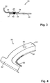
- Fig. 4 shows the foot region of a press-hardened B-pillar 50 (strictly speaking, it is an internal reinforcing member for a B-pillar), which in a Body structure is integrated for a motor vehicle.
- the B pillar 50 comprises a longitudinal profile section 51, which merges into a transverse profile section 52 in the lower region.
- the reference numeral 53 denotes a lower door hinge connection.
- 54 designates a joining flange or mounting flange by means of which the B pillar 50 can be integrated into the body structure, for which purpose at least one welded joint is arranged along this joining flange 54, in the form of a plurality of welding points and / or at least one weld seam.
- the reference numeral 55 denotes a portion of the joining flange 54, which extends approximately from the lower door hinge connection 53 to the outlet of the component curvature at the transition between the longitudinal profile section 51 and the cross-sectional section 52. It has been found that with a mechanical loading of the B-pillar 50, in particular with a highly dynamic load such as, for example, in a side impact, a weld in this section 55 is particularly critical to crack initiation. This is e.g. attributed to the fact that a concomitant with a side impact inflection of the longitudinal profile section 51 has a strong tensile load in this section 55 of the joint flange 54 result.
- this critical section 55 of the joining flange 54 is already formed from the press-hardening process with a lower strength and / or hardness than the other sections of the press-hardened B-pillar 50.
- preferred possibilities for producing such a B-pillar are described. Pillar shown.
- Fig. 5 shows a press hardening tool 60 for the production of the B-pillar 50 from the Fig. 4 in a partial section, which includes the critical portion 55 of the joint flange 54.
- the press hardening tool 60 is formed of a lower die 61 and an upper die 62. Alternatively, the press hardening tool 60 may also be constructed in several parts. Not shown are any cooling devices within the pressing tool 60, which is referenced representative of the above-mentioned prior art.
- an insert 63 is arranged in the upper tool 62.
- the insert 63 extends along the in Fig. 4 hatched shown critical portion 55 of the joint flange 54, which is apparent from the Fig. 5 is not apparent.
- This insert 63 may for example be formed of a material which has a different heat capacity and / or heat conduction with respect to the tool material, such as a ceramic material, whereby a slower cooling of the critical portion 55 of the joining flange 54 relative to the other regions of the B-pillar 50 achieved and eg a structural transformation is prevented.
- the insert 63 is here arranged such that at the B-pillar 50 the transition radius R to the critical portion 55 of the joining flange 54 is still included in the press hardening. Alternatively and / or additionally, the insert 63 can also be arranged in the lower tool 61. The insert 63 need not reach the outer edge of the press hardening tool 60, as shown.
- the insert 63 may also be an actively heatable heating element, by means of which the cooling in the critical section 55 of the joining flange 54 can be influenced directly.
- this heating element can be coupled to a control unit.
- a heating device can also be installed directly in the upper tool 62 and / or lower tool 61.
- Fig. 6 shows an alternative embodiment of a press hardening tool 60a for making the B-pillar 50 of FIG Fig. 4
- the structure of the press-hardening tool 60a substantially corresponds to the structure of the press-hardening tool 60 of FIG Fig. 5
- a recess or an air gap 64a is provided in the upper tool 62a, which causes a slower cooling of the critical portion 55 of the Fügeflansches 54, with respect to the other on the lower tool 61a and the upper tool 62a adjacent areas of the B-pillar during press hardening process 50.
- the air gap 64a may alternatively and / or additionally also be arranged in the lower tool 61a. Furthermore, the Air gap 64 a also be led to the outer edge of the press hardening tool 60 a, as in Fig. 5 shown insert 63.
Landscapes
- Engineering & Computer Science (AREA)
- Chemical & Material Sciences (AREA)
- Mechanical Engineering (AREA)
- Physics & Mathematics (AREA)
- Thermal Sciences (AREA)
- Crystallography & Structural Chemistry (AREA)
- Materials Engineering (AREA)
- Metallurgy (AREA)
- Organic Chemistry (AREA)
- Body Structure For Vehicles (AREA)
Claims (6)
- Structure de carrosserie destinée à un véhicule de tourisme comprenant une colonne B trempée sous pression (50) qui est intégrée dans cette structure de carrosserie par l'intermédiaire d'au moins une liaison soudée, la colonne B trempée sous pression (50) comprenant une bride de jonction (54), et la liaison soudée étant située dans la zone de cette bride de jonction (54),
caractérisée en ce que
la colonne B trempée sous pression (50) a, dans la zone de la liaison soudée, localement dans un segment (55) de la bride de jonction (54) une résistance et/ou une dureté plus faible(s) que dans ses autres zones pour éviter un amorçage de fissures dans la zone de cette liaison soudée en cas de charge mécanique, le segment (55) de la bride de jonction (54) s'étendant d'une liaison de charnière de porte inférieure (53) jusqu'à la sortie de la courbure de la pièce au niveau de la transition entre un segment de profil longitudinal (51) et un segment de profil transversal (52), et étant déjà formé à l'issue du procédé de trempe sous pression avec une résistance et/ou une dureté plus faible(s). - Structure de carrosserie conforme à la revendication 1,
caractérisée en ce que
la liaison soudée est un point de soudure (40). - Structure de carrosserie conforme à la revendication 2,
caractérisée en ce que
la zone ayant une résistance et/ou une dureté plus faible(s) est une zone de surface qui correspond à au moins 15 fois, de préférence à au moins 10 fois et plus particulièrement à au moins 5 fois la surface du point de soudure, le point de soudure (40) étant de préférence situé au centre de gravité de cette zone de surface. - Structure de carrosserie conforme à la revendication 1,
caractérisée en ce que
la liaison soudée est un cordon de soudure. - Structure de carrosserie conforme à la revendication 4,
caractérisée en ce que
la zone ayant une résistance et/ou une dureté plus faible(s) correspond à une zone de surface qui s'étend le long du tracé du cordon de soudure, la largeur de cette zone correspondant à au moins 10 fois de préférence à au moins 5 fois et de préférence à au moins 2,5 fois la largeur du cordon de soudure, et le cordon de soudure s'étendant essentiellement au centre de cette zone de surface. - Structure de carrosserie conforme à l'une des revendications précédentes,
caractérisée en ce que
la colonne B trempée sous pression (50) est réalisée en un acier 22MnB5.
Applications Claiming Priority (1)
| Application Number | Priority Date | Filing Date | Title |
|---|---|---|---|
| DE102009020423A DE102009020423A1 (de) | 2009-05-08 | 2009-05-08 | Teileverbund mit einem pressgehärteten Blechbauteil |
Publications (2)
| Publication Number | Publication Date |
|---|---|
| EP2248623A1 EP2248623A1 (fr) | 2010-11-10 |
| EP2248623B1 true EP2248623B1 (fr) | 2019-07-24 |
Family
ID=42646284
Family Applications (1)
| Application Number | Title | Priority Date | Filing Date |
|---|---|---|---|
| EP10003816.5A Active EP2248623B1 (fr) | 2009-05-08 | 2010-04-09 | Structure de carrosserie dotée d'un pied-milieu durci à la presse |
Country Status (2)
| Country | Link |
|---|---|
| EP (1) | EP2248623B1 (fr) |
| DE (1) | DE102009020423A1 (fr) |
Families Citing this family (8)
| Publication number | Priority date | Publication date | Assignee | Title |
|---|---|---|---|---|
| SE533528C2 (sv) | 2009-12-13 | 2010-10-19 | Gestamp Hardtech Ab | B-stolpe för fordon |
| ES2345029B1 (es) | 2010-04-19 | 2011-07-18 | Autotech Engineering, Aie | Componente estructural de un vehiculo y procedimiento de fabricacion. |
| DE102011055643A1 (de) * | 2011-11-23 | 2013-05-23 | Thyssenkrupp Steel Europe Ag | Verfahren und Umformwerkzeug zum Warmumformen und Presshärten von Werkstücken aus Stahlblech, insbesondere verzinkten Werkstücken aus Stahlblech |
| JP6535029B2 (ja) * | 2014-02-17 | 2019-06-26 | イェスタムプ・ハードテック・アクチエボラーグ | 細長い溶接部およびそうした溶接部を有するビーム |
| DE102014221997A1 (de) | 2014-10-29 | 2016-05-04 | Bayerische Motoren Werke Aktiengesellschaft | Formwerkzeug zur Herstellung von warmumgeformten Bauteilen |
| DE102016201036A1 (de) | 2016-01-26 | 2017-07-27 | Zf Friedrichshafen Ag | Verfahren zur Herstellung eines Bauteils und nach diesem Verfahren hergestelltes Bauteil |
| EP4054777B1 (fr) * | 2019-11-08 | 2023-09-13 | Autotech Engineering S.L. | Pièce de formation en tôle pour châssis de véhicule et procédé de production correspondant |
| WO2023102648A1 (fr) * | 2021-12-08 | 2023-06-15 | Magna International Inc. | Système et procédé d'estampage à chaud |
Citations (1)
| Publication number | Priority date | Publication date | Assignee | Title |
|---|---|---|---|---|
| EP1180470A1 (fr) * | 2000-08-19 | 2002-02-20 | Benteler Ag | Montant central pour véhicule |
Family Cites Families (5)
| Publication number | Priority date | Publication date | Assignee | Title |
|---|---|---|---|---|
| DE10323746A1 (de) * | 2003-05-24 | 2004-12-09 | Daimlerchrysler Ag | Verfahren zur Reparatur eines metallischen Bauteils |
| DE102005032113B3 (de) * | 2005-07-07 | 2007-02-08 | Schwartz, Eva | Verfahren und Vorrichtung zum Warmumformen und partiellen Härten eines Bauteils |
| DE102005055374A1 (de) * | 2005-11-17 | 2007-05-24 | Victocor Technologies S.A. | Hochfestes Stahlbauteil mit Korrosionsschutzschicht aus Zink |
| DE102007040028B4 (de) | 2007-08-24 | 2019-11-07 | Bayerische Motoren Werke Aktiengesellschaft | Werkzeug für das Warmumformen oder Presshärten eines Metallblechs |
| DE102007040013B4 (de) | 2007-08-24 | 2026-04-30 | Bayerische Motoren Werke Aktiengesellschaft | Werkzeug für das Warmumformen oder Presshärten eines Metallblechs sowie Verfahren zur Einstellung des Kühlverhaltens eines Werkzeugs |
-
2009
- 2009-05-08 DE DE102009020423A patent/DE102009020423A1/de active Pending
-
2010
- 2010-04-09 EP EP10003816.5A patent/EP2248623B1/fr active Active
Patent Citations (1)
| Publication number | Priority date | Publication date | Assignee | Title |
|---|---|---|---|---|
| EP1180470A1 (fr) * | 2000-08-19 | 2002-02-20 | Benteler Ag | Montant central pour véhicule |
Also Published As
| Publication number | Publication date |
|---|---|
| EP2248623A1 (fr) | 2010-11-10 |
| DE102009020423A1 (de) | 2010-11-11 |
Similar Documents
| Publication | Publication Date | Title |
|---|---|---|
| EP2248623B1 (fr) | Structure de carrosserie dotée d'un pied-milieu durci à la presse | |
| EP2025560B1 (fr) | Procédé de fabrication d'un agencement de pare-chocs d'un véhicule automobile | |
| EP3045551B1 (fr) | Procédé de traitement thermique partiel d'un composant de véhicule automobile déformé à chaud et trempé sous presse | |
| DE102010012832B4 (de) | Kraftfahrzeugsäule | |
| DE102014008718B3 (de) | Maßgeschneidertes Halbzeug und Kraftfahrzeugbauteil | |
| WO2008068346A2 (fr) | Assemblage constitué de deux tôles d'acier | |
| EP2195226A1 (fr) | Procédé pour fabriquer un assemblage de composants principalement plat et assemblage de composants principalement plat | |
| EP2948327B1 (fr) | Structure intermédiaire pour porte de véhicule automobile, procédé de production d'une structure intermédiaire et porte pour véhicule automobile | |
| DE102015114989B3 (de) | Verfahren zum Herstellen einer Bauteilstruktur mit verbesserten Fügeeigenschaften und Bauteilstruktur | |
| EP3408162B1 (fr) | Procédé pour produire un élément et élément produit au moyen de ce procédé | |
| DE102013012478A1 (de) | Karosseriebauteil sowie Verfahren zur Herstellung eines Karosseriebauteils | |
| DE102004032599B4 (de) | A-Säule an einer Kraftfahrzeugkarosserie eines Cabrio-Fahrzeuges | |
| DE102010012833B4 (de) | Längsträger sowie Längsträgeranordnung | |
| EP0882639A2 (fr) | Elément pour la fabrication de carrosserie de véhicules automobiles et méthode de sa manufacture | |
| EP2942418A1 (fr) | Procédé de fabrication d'un élément de véhicule automobile en aluminium | |
| EP3296104B1 (fr) | Procédé de fabrication d'un élément de carrosserie à tendance réduite à la fissuration | |
| EP1357017B1 (fr) | Chassis de véhicule en treillis | |
| DE102016013301A1 (de) | Fahrzeugsäule für ein Kraftfahrzeug und Verfahren zum Herstellen einer Fahrzeugsäule für ein Kraftfahrzeug | |
| DE102018107846B4 (de) | Verfahren zum Herstellen eines Profilbauteils sowie Fahrzeugquerträger oder Fahrzeuglängsträger | |
| DE202021101463U1 (de) | Lasergeschweißte Schweißkonstruktion | |
| DE102020109579A1 (de) | Träger für ein Kraftfahrzeug und Verfahren zur Herstellung eines Trägers | |
| DE102010041863B4 (de) | Kraftfahrzeug mit einem Blechbauteil | |
| DE102021123788B4 (de) | Kraftfahrzeug-Biegeträger | |
| DE102018109992A1 (de) | Kraftfahrzeug-Stoßfängeranordnung und Verfahren zur Herstellung | |
| DE102023113543A1 (de) | Karosserieelement, Kraftfahrzeugkarosserie, Kraftfahrzeug sowie Verfahren zur Herstellung eines Karosserieelements |
Legal Events
| Date | Code | Title | Description |
|---|---|---|---|
| PUAI | Public reference made under article 153(3) epc to a published international application that has entered the european phase |
Free format text: ORIGINAL CODE: 0009012 |
|
| AK | Designated contracting states |
Kind code of ref document: A1 Designated state(s): AT BE BG CH CY CZ DE DK EE ES FI FR GB GR HR HU IE IS IT LI LT LU LV MC MK MT NL NO PL PT RO SE SI SK SM TR |
|
| AX | Request for extension of the european patent |
Extension state: AL BA ME RS |
|
| 17P | Request for examination filed |
Effective date: 20101211 |
|
| RAP1 | Party data changed (applicant data changed or rights of an application transferred) |
Owner name: BAYERISCHE MOTOREN WERKE AKTIENGESELLSCHAFT |
|
| STAA | Information on the status of an ep patent application or granted ep patent |
Free format text: STATUS: EXAMINATION IS IN PROGRESS |
|
| 17Q | First examination report despatched |
Effective date: 20170208 |
|
| GRAP | Despatch of communication of intention to grant a patent |
Free format text: ORIGINAL CODE: EPIDOSNIGR1 |
|
| STAA | Information on the status of an ep patent application or granted ep patent |
Free format text: STATUS: GRANT OF PATENT IS INTENDED |
|
| INTG | Intention to grant announced |
Effective date: 20190408 |
|
| GRAS | Grant fee paid |
Free format text: ORIGINAL CODE: EPIDOSNIGR3 |
|
| GRAA | (expected) grant |
Free format text: ORIGINAL CODE: 0009210 |
|
| STAA | Information on the status of an ep patent application or granted ep patent |
Free format text: STATUS: THE PATENT HAS BEEN GRANTED |
|
| AK | Designated contracting states |
Kind code of ref document: B1 Designated state(s): AT BE BG CH CY CZ DE DK EE ES FI FR GB GR HR HU IE IS IT LI LT LU LV MC MK MT NL NO PL PT RO SE SI SK SM TR |
|
| REG | Reference to a national code |
Ref country code: GB Ref legal event code: FG4D Free format text: NOT ENGLISH |
|
| REG | Reference to a national code |
Ref country code: CH Ref legal event code: EP |
|
| REG | Reference to a national code |
Ref country code: DE Ref legal event code: R096 Ref document number: 502010016145 Country of ref document: DE |
|
| REG | Reference to a national code |
Ref country code: AT Ref legal event code: REF Ref document number: 1157614 Country of ref document: AT Kind code of ref document: T Effective date: 20190815 |
|
| REG | Reference to a national code |
Ref country code: IE Ref legal event code: FG4D Free format text: LANGUAGE OF EP DOCUMENT: GERMAN |
|
| REG | Reference to a national code |
Ref country code: NL Ref legal event code: MP Effective date: 20190724 |
|
| REG | Reference to a national code |
Ref country code: LT Ref legal event code: MG4D |
|
| PG25 | Lapsed in a contracting state [announced via postgrant information from national office to epo] |
Ref country code: FI Free format text: LAPSE BECAUSE OF FAILURE TO SUBMIT A TRANSLATION OF THE DESCRIPTION OR TO PAY THE FEE WITHIN THE PRESCRIBED TIME-LIMIT Effective date: 20190724 Ref country code: LT Free format text: LAPSE BECAUSE OF FAILURE TO SUBMIT A TRANSLATION OF THE DESCRIPTION OR TO PAY THE FEE WITHIN THE PRESCRIBED TIME-LIMIT Effective date: 20190724 Ref country code: HR Free format text: LAPSE BECAUSE OF FAILURE TO SUBMIT A TRANSLATION OF THE DESCRIPTION OR TO PAY THE FEE WITHIN THE PRESCRIBED TIME-LIMIT Effective date: 20190724 Ref country code: SE Free format text: LAPSE BECAUSE OF FAILURE TO SUBMIT A TRANSLATION OF THE DESCRIPTION OR TO PAY THE FEE WITHIN THE PRESCRIBED TIME-LIMIT Effective date: 20190724 Ref country code: NO Free format text: LAPSE BECAUSE OF FAILURE TO SUBMIT A TRANSLATION OF THE DESCRIPTION OR TO PAY THE FEE WITHIN THE PRESCRIBED TIME-LIMIT Effective date: 20191024 Ref country code: NL Free format text: LAPSE BECAUSE OF FAILURE TO SUBMIT A TRANSLATION OF THE DESCRIPTION OR TO PAY THE FEE WITHIN THE PRESCRIBED TIME-LIMIT Effective date: 20190724 Ref country code: PT Free format text: LAPSE BECAUSE OF FAILURE TO SUBMIT A TRANSLATION OF THE DESCRIPTION OR TO PAY THE FEE WITHIN THE PRESCRIBED TIME-LIMIT Effective date: 20191125 Ref country code: BG Free format text: LAPSE BECAUSE OF FAILURE TO SUBMIT A TRANSLATION OF THE DESCRIPTION OR TO PAY THE FEE WITHIN THE PRESCRIBED TIME-LIMIT Effective date: 20191024 |
|
| PG25 | Lapsed in a contracting state [announced via postgrant information from national office to epo] |
Ref country code: LV Free format text: LAPSE BECAUSE OF FAILURE TO SUBMIT A TRANSLATION OF THE DESCRIPTION OR TO PAY THE FEE WITHIN THE PRESCRIBED TIME-LIMIT Effective date: 20190724 Ref country code: ES Free format text: LAPSE BECAUSE OF FAILURE TO SUBMIT A TRANSLATION OF THE DESCRIPTION OR TO PAY THE FEE WITHIN THE PRESCRIBED TIME-LIMIT Effective date: 20190724 Ref country code: GR Free format text: LAPSE BECAUSE OF FAILURE TO SUBMIT A TRANSLATION OF THE DESCRIPTION OR TO PAY THE FEE WITHIN THE PRESCRIBED TIME-LIMIT Effective date: 20191025 Ref country code: IS Free format text: LAPSE BECAUSE OF FAILURE TO SUBMIT A TRANSLATION OF THE DESCRIPTION OR TO PAY THE FEE WITHIN THE PRESCRIBED TIME-LIMIT Effective date: 20191124 |
|
| PG25 | Lapsed in a contracting state [announced via postgrant information from national office to epo] |
Ref country code: TR Free format text: LAPSE BECAUSE OF FAILURE TO SUBMIT A TRANSLATION OF THE DESCRIPTION OR TO PAY THE FEE WITHIN THE PRESCRIBED TIME-LIMIT Effective date: 20190724 |
|
| PG25 | Lapsed in a contracting state [announced via postgrant information from national office to epo] |
Ref country code: EE Free format text: LAPSE BECAUSE OF FAILURE TO SUBMIT A TRANSLATION OF THE DESCRIPTION OR TO PAY THE FEE WITHIN THE PRESCRIBED TIME-LIMIT Effective date: 20190724 Ref country code: PL Free format text: LAPSE BECAUSE OF FAILURE TO SUBMIT A TRANSLATION OF THE DESCRIPTION OR TO PAY THE FEE WITHIN THE PRESCRIBED TIME-LIMIT Effective date: 20190724 Ref country code: RO Free format text: LAPSE BECAUSE OF FAILURE TO SUBMIT A TRANSLATION OF THE DESCRIPTION OR TO PAY THE FEE WITHIN THE PRESCRIBED TIME-LIMIT Effective date: 20190724 Ref country code: DK Free format text: LAPSE BECAUSE OF FAILURE TO SUBMIT A TRANSLATION OF THE DESCRIPTION OR TO PAY THE FEE WITHIN THE PRESCRIBED TIME-LIMIT Effective date: 20190724 |
|
| PG25 | Lapsed in a contracting state [announced via postgrant information from national office to epo] |
Ref country code: SK Free format text: LAPSE BECAUSE OF FAILURE TO SUBMIT A TRANSLATION OF THE DESCRIPTION OR TO PAY THE FEE WITHIN THE PRESCRIBED TIME-LIMIT Effective date: 20190724 Ref country code: IS Free format text: LAPSE BECAUSE OF FAILURE TO SUBMIT A TRANSLATION OF THE DESCRIPTION OR TO PAY THE FEE WITHIN THE PRESCRIBED TIME-LIMIT Effective date: 20200224 Ref country code: SM Free format text: LAPSE BECAUSE OF FAILURE TO SUBMIT A TRANSLATION OF THE DESCRIPTION OR TO PAY THE FEE WITHIN THE PRESCRIBED TIME-LIMIT Effective date: 20190724 Ref country code: CZ Free format text: LAPSE BECAUSE OF FAILURE TO SUBMIT A TRANSLATION OF THE DESCRIPTION OR TO PAY THE FEE WITHIN THE PRESCRIBED TIME-LIMIT Effective date: 20190724 |
|
| REG | Reference to a national code |
Ref country code: DE Ref legal event code: R097 Ref document number: 502010016145 Country of ref document: DE |
|
| PLBE | No opposition filed within time limit |
Free format text: ORIGINAL CODE: 0009261 |
|
| STAA | Information on the status of an ep patent application or granted ep patent |
Free format text: STATUS: NO OPPOSITION FILED WITHIN TIME LIMIT |
|
| PG2D | Information on lapse in contracting state deleted |
Ref country code: IS |
|
| 26N | No opposition filed |
Effective date: 20200603 |
|
| PG25 | Lapsed in a contracting state [announced via postgrant information from national office to epo] |
Ref country code: SI Free format text: LAPSE BECAUSE OF FAILURE TO SUBMIT A TRANSLATION OF THE DESCRIPTION OR TO PAY THE FEE WITHIN THE PRESCRIBED TIME-LIMIT Effective date: 20190724 |
|
| PG25 | Lapsed in a contracting state [announced via postgrant information from national office to epo] |
Ref country code: MC Free format text: LAPSE BECAUSE OF FAILURE TO SUBMIT A TRANSLATION OF THE DESCRIPTION OR TO PAY THE FEE WITHIN THE PRESCRIBED TIME-LIMIT Effective date: 20190724 |
|
| REG | Reference to a national code |
Ref country code: CH Ref legal event code: PL |
|
| PG25 | Lapsed in a contracting state [announced via postgrant information from national office to epo] |
Ref country code: CH Free format text: LAPSE BECAUSE OF NON-PAYMENT OF DUE FEES Effective date: 20200430 Ref country code: LU Free format text: LAPSE BECAUSE OF NON-PAYMENT OF DUE FEES Effective date: 20200409 Ref country code: LI Free format text: LAPSE BECAUSE OF NON-PAYMENT OF DUE FEES Effective date: 20200430 |
|
| REG | Reference to a national code |
Ref country code: BE Ref legal event code: MM Effective date: 20200430 |
|
| PG25 | Lapsed in a contracting state [announced via postgrant information from national office to epo] |
Ref country code: BE Free format text: LAPSE BECAUSE OF NON-PAYMENT OF DUE FEES Effective date: 20200430 |
|
| PG25 | Lapsed in a contracting state [announced via postgrant information from national office to epo] |
Ref country code: IE Free format text: LAPSE BECAUSE OF NON-PAYMENT OF DUE FEES Effective date: 20200409 |
|
| REG | Reference to a national code |
Ref country code: AT Ref legal event code: MM01 Ref document number: 1157614 Country of ref document: AT Kind code of ref document: T Effective date: 20200409 |
|
| PG25 | Lapsed in a contracting state [announced via postgrant information from national office to epo] |
Ref country code: AT Free format text: LAPSE BECAUSE OF NON-PAYMENT OF DUE FEES Effective date: 20200409 |
|
| PG25 | Lapsed in a contracting state [announced via postgrant information from national office to epo] |
Ref country code: MT Free format text: LAPSE BECAUSE OF FAILURE TO SUBMIT A TRANSLATION OF THE DESCRIPTION OR TO PAY THE FEE WITHIN THE PRESCRIBED TIME-LIMIT Effective date: 20190724 Ref country code: CY Free format text: LAPSE BECAUSE OF FAILURE TO SUBMIT A TRANSLATION OF THE DESCRIPTION OR TO PAY THE FEE WITHIN THE PRESCRIBED TIME-LIMIT Effective date: 20190724 |
|
| PG25 | Lapsed in a contracting state [announced via postgrant information from national office to epo] |
Ref country code: MK Free format text: LAPSE BECAUSE OF FAILURE TO SUBMIT A TRANSLATION OF THE DESCRIPTION OR TO PAY THE FEE WITHIN THE PRESCRIBED TIME-LIMIT Effective date: 20190724 |
|
| P01 | Opt-out of the competence of the unified patent court (upc) registered |
Effective date: 20230502 |
|
| PGFP | Annual fee paid to national office [announced via postgrant information from national office to epo] |
Ref country code: DE Payment date: 20250408 Year of fee payment: 16 |
|
| PGFP | Annual fee paid to national office [announced via postgrant information from national office to epo] |
Ref country code: IT Payment date: 20250430 Year of fee payment: 16 |
|
| PGFP | Annual fee paid to national office [announced via postgrant information from national office to epo] |
Ref country code: FR Payment date: 20250422 Year of fee payment: 16 |
|
| PGFP | Annual fee paid to national office [announced via postgrant information from national office to epo] |
Ref country code: GB Payment date: 20260324 Year of fee payment: 17 |