EP2248760B1 - Verfahren und Vorrichtung zur Befüllung von Baugruppen mit Betriebsstoffen an Fertigungslinien der Automobilindustrie - Google Patents
Verfahren und Vorrichtung zur Befüllung von Baugruppen mit Betriebsstoffen an Fertigungslinien der Automobilindustrie Download PDFInfo
- Publication number
- EP2248760B1 EP2248760B1 EP10004685.3A EP10004685A EP2248760B1 EP 2248760 B1 EP2248760 B1 EP 2248760B1 EP 10004685 A EP10004685 A EP 10004685A EP 2248760 B1 EP2248760 B1 EP 2248760B1
- Authority
- EP
- European Patent Office
- Prior art keywords
- filling
- traversing
- adapter
- console
- gripper
- Prior art date
- Legal status (The legal status is an assumption and is not a legal conclusion. Google has not performed a legal analysis and makes no representation as to the accuracy of the status listed.)
- Active
Links
Images


Classifications
-
- B—PERFORMING OPERATIONS; TRANSPORTING
- B25—HAND TOOLS; PORTABLE POWER-DRIVEN TOOLS; MANIPULATORS
- B25J—MANIPULATORS; CHAMBERS PROVIDED WITH MANIPULATION DEVICES
- B25J5/00—Manipulators mounted on wheels or on carriages
- B25J5/02—Manipulators mounted on wheels or on carriages travelling along a guideway
-
- B—PERFORMING OPERATIONS; TRANSPORTING
- B25—HAND TOOLS; PORTABLE POWER-DRIVEN TOOLS; MANIPULATORS
- B25J—MANIPULATORS; CHAMBERS PROVIDED WITH MANIPULATION DEVICES
- B25J17/00—Joints
- B25J17/02—Wrist joints
- B25J17/0208—Compliance devices
-
- B—PERFORMING OPERATIONS; TRANSPORTING
- B67—OPENING, CLOSING OR CLEANING BOTTLES, JARS OR SIMILAR CONTAINERS; LIQUID HANDLING
- B67D—DISPENSING, DELIVERING OR TRANSFERRING LIQUIDS, NOT OTHERWISE PROVIDED FOR
- B67D7/00—Apparatus or devices for transferring liquids from bulk storage containers or reservoirs into vehicles or into portable containers, e.g. for retail sale purposes
- B67D7/04—Apparatus or devices for transferring liquids from bulk storage containers or reservoirs into vehicles or into portable containers, e.g. for retail sale purposes for transferring fuels, lubricants or mixed fuels and lubricants
- B67D7/0401—Apparatus or devices for transferring liquids from bulk storage containers or reservoirs into vehicles or into portable containers, e.g. for retail sale purposes for transferring fuels, lubricants or mixed fuels and lubricants arrangements for automatically fuelling vehicles, i.e. without human intervention
Definitions
- the invention relates to a method and a device for filling assemblies with operating materials on production lines in the automotive industry, the respective vehicle being guided along the production line and being filled during this movement using at least one filling adapter.
- containers have to be filled with liquids or gases.
- a typical area of application in this regard are production lines in the automotive industry, on which housings, expansion tanks and similar vehicle assemblies are filled with fuel, lubricants, coolants and other operating materials for the first time.
- the respective assembly is temporarily connected to an adapter through which the corresponding medium is fed.
- Such filling adapters are known in various designs.
- the JP S 60 148496 A shows an industrial robot with a gripper hand that grips a filling adapter to fill a vehicle.
- the object of the invention is to create a technical solution for filling assemblies with operating materials on production lines in the automotive industry, which is suitable for handling several different filling adapters at several different positions and requires only little manual effort.
- the extraction system essentially has the following structure: In order to be able to remove filling adapters from a vehicle moving with the assembly line, several travel assemblies must be controlled in such a way that they run synchronously. This ensures that the gripping positions are reached and a collision of the industrial robot with the vehicle is avoided. It will a connection is established between a front wheel of the vehicle to be filled and the moving console on the one hand and the moving carriage of the robot axis (with the industrial robot) and the moving console on the other. These connections are each equipped with a measuring system so that the elements are not rigidly connected, but have their own drives that are synchronized and monitored accordingly.
- the filling adapter Due to tolerances in the vehicle and in the overall system, the position of the filling adapter to be removed will deviate from the target position in the mm range.
- the filling adapter is provided with a gripping element and the gripper itself is constructed in such a way that a compensation mechanism is set in motion during the gripping movement, with which an angular and / or axial offset can be compensated . Before the filling adapter is put down, this compensation mechanism is set to the zero position.
- the elimination of a mechanical feed system improves accessibility when adapting the filling adapter in the vehicle. Furthermore, the integration of new filling adapters is possible without any problems. Furthermore, container positions can be quickly integrated in the event of a change. In addition, this standard solution with a robot system is easier to organize in terms of maintenance and servicing than a special solution. Finally, a worker can be released for other tasks.
- Fig. 1 and Fig. 2 show in two views a device according to the invention, which is preferably designed for the initial filling of housings, expansion tanks and similar vehicle assemblies with fuel, lubricants, coolants and other operating materials on production lines in the automotive industry.
- the respective vehicle 1 is guided along the production line and filled during this movement using at least one filling adapter.
- the structure of such a production line with transport system 2, protective fence 3, tools 4 and other assemblies is known per se, so that further explanations in this regard can be dispensed with.
- the assembly to be filled is first assigned a filling adapter 5. This is preferably done manually by a worker. This is followed by an automatic filling. After completion of this filling, according to the invention, the at least one filling adapter 5 is removed from the connection area of the assembly to be filled by means of an industrial robot 6 and then stored in an adapter tray, such a tray not being shown in detail in the drawing.
- the device comprises a rail system 7 with a travel axis 8 and a travel console 9.
- the industrial robot 6 is guided on the travel axis 8.
- the moving consoles 9 hang and move in the rail system 7, which is attached to a steel structure.
- the travel axis 8 hangs on the same steel structure as the rail system 7 and moves a slide to which the industrial robot 6 is attached.
- the industrial robot 6 has a compensating gripper which can be brought into operative connection with a gripping element configured on the filling adapter 5.
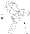
- Fig. 3 shows only an example of a corresponding embodiment, wherein the compensating gripper and the gripping element can be designed in different ways, taking into account the specific application conditions in each case. Regardless of the specific variant, however, the compensating gripper and the gripping element are designed in such a way that a compensating mechanism can be triggered during the gripping movement which can compensate for an angular and / or axial offset. This compensation mechanism is set to a defined ZERO position before the filling adapter is put down.
- a connection is configured in each case between a front wheel of the vehicle 1 guided along the production line and the traversing console 9 and between the traversing slide of the robot axis 8 with the industrial robot 6 and the traversing console 9.
- the connections are each equipped with a measuring system, each of which has its own drive assigned to it. These drives are operated and monitored synchronized with each other.
Landscapes
- Engineering & Computer Science (AREA)
- Mechanical Engineering (AREA)
- Robotics (AREA)
- Automobile Manufacture Line, Endless Track Vehicle, Trailer (AREA)
- Automatic Assembly (AREA)
Description
- Die Erfindung betrifft ein Verfahren und eine Vorrichtung zur Befüllung von Baugruppen mit Betriebsstoffen an Fertigungslinien der Automobilindustrie, wobei das jeweilige Fahrzeug entlang der Fertigungslinie geführt und während dieser Bewegung unter Verwendung von mindestens einem Befülladapter befüllt wird.
- Für zahlreiche technische Anwendungen müssen Behälter mit Flüssigkeiten oder Gasen gefüllt werden. Ein diesbezüglich typisches Anwendungsgebiet sind Fertigungslinien in der Automobilindustrie, an denen eine Erstbefüllung von Gehäusen, Ausgleichbehältern und ähnlichen Fahrzeugbaugruppen mit Kraft-, Schmier-, Kühl- und sonstigen Betriebsstoffen erfolgt. Für den Befüllvorgang wird die jeweilige Baugruppe temporär mit einem Adapter verbunden, über den das entsprechende Medium zugeführt wird. Derartige Befülladapter sind in verschiedenartigen Ausführungen bekannt.
- So beschreibt
GB 2 002 720 A - Aus
US 4 109 686 A ist ein Adapter zur Befüllung von Kraftfahrzeugbaugruppen bekannt, der an seiner Stirnfläche Vorsprünge aufweist, die mit hierzu kongruenten Ausnehmungen an der zu befüllenden Baugruppe in Wirkverbindung gebracht werden. Der Adapter wird zunächst mit den Vorsprüngen in die Ausnehmungen eingesetzt und danach verdreht. - In
DE 28 48 434 C2 wird ein weiterer Befülladapter beschrieben, der ein Gehäuse mit einem axial verlaufenden Füllrohr für das in einen Einfüllstutzen einer zugeordneten Baugruppe einzufüllende Medium aufweist. Der jeweilige Betriebsstoff wird über Schläuche oder ähnliche Leitungen zugeführt und strömt im Innenraum des Gehäuses über Kanalstrukturen zum Füllrohr. Am Gehäuse sind schwenkbewegliche Spannklauen abgestützt, die mit Ausnehmungen am Einfüllstutzen in Wirkverbindung gebracht werden. - Die
JP S 60 148496 A - Unabhängig von der jeweils konkreten Ausführung der Befülladapter sind für die Befüllung an Fertigungslinien der Automobilindustrie bisher zwei Varianten üblich:
- a) Die Befülladapter werden nach beendetem Befüllvorgang vom Medienvorratsbehälter von Hand abgenommen und in einer Adapterablage der Verfahrkonsole abgelegt. Diese Handhabung muss ein Werker verrichten.
- b) Die Befülladapter werden nach beendetem Befüllvorgang durch ein Handlingsystem in definierte Aufnahmen gezogen und in eine Transportposition gefahren. Hierbei ergeben sich Probleme, sofern mehrere unterschiedliche Befülladapter an mehreren unterschiedlichen Positionen eingesetzt werden müssen. Beispielsweise ist bei einem Einsatz von fünf verschiedenen Befülladaptern mit jeweils mehreren unterschiedlichen Positionen im Vorderwagen von sechs zu befüllenden Fahrzeugtypen eine konventionelle Zustellung im vorgegebenen Arbeitsbereich nicht möglich.
- Die Broschüre "Automotive Filling & Testing Systems" der Sterling Fluid Systems Group - Sterling SAT / Sterling PCU (April 2009) beschreibt ein Verfahren zur Befüllung von Baugruppen mit Betriebsstoffen an Fertigungslinien der Automobilindustrie, wobei das jeweilige Fahrzeug entlang der Fertigungslinie geführt und während dieser Bewegung unter Verwendung von mindestens einem Befülladapter befüllt wird. Der Befülladapter wird nach der Befüllung durch einen Industrieroboter aus dem Bereich der zu befüllenden Baugruppe entnommen und nachfolgend in einer Adapterablage abgelegt.
- Aufgabe der Erfindung ist es, eine technische Lösung zur Befüllung von Baugruppen mit Betriebsstoffen an Fertigungslinien der Automobilindustrie zu schaffen, die zur Handhabung mehrerer unterschiedlicher Befülladapter an mehreren unterschiedlichen Positionen geeignet ist und einen lediglich geringen manuellen Aufwand erfordert.
- Diese Aufgabe wird mit den technischen Merkmalen des Anspruchs 1 gelöst.
- Vorteilhafte Ausgestaltungen sind Gegenstand von Unteransprüchen, deren technische Merkmale in einem Ausführungsbeispiel näher beschrieben werden.
- Gemäß der Erfindung wird vorgeschlagen, die Befülladapter mittels eines auf einer Achse geführten Industrieroboters mit einem speziellen Ausgleichsgreifer nach der Befüllung zu entnehmen und diese in einer Adapterablage abzulegen. Um diesen Verfahrensablauf realisieren zu können, weist das Entnahmesystem im Wesentlichen folgenden Aufbau auf:
Um Befülladapter aus einem, sich mit dem Montageband bewegenden Fahrzeug entnehmen zu können, müssen mehrere Verfahrbaugruppen so gesteuert werden, dass sie synchron laufen. Dadurch wird gewährleistet, dass die Greifpositionen erreicht werden und eine Kollision des Industrieroboters mit dem Fahrzeug vermieden wird. Dabei wird eine Verbindung zwischen einem Vorderrad des zu befüllenden Fahrzeuges und der Verfahrkonsole einerseits sowie dem Verfahrschlitten der Roboterachse (mit dem Industrieroboter) und der Verfahrkonsole andererseits hergestellt. Diese Verbindungen sind mit jeweils einem Messsystem ausgerüstet, so dass die Elemente nicht starr verbunden sind, sondern eigene Antriebe besitzen, die entsprechend synchronisiert und überwacht werden. - Durch Toleranzen im Fahrzeug und im Gesamtsystem wird die Position der zu entnehmenden Befülladapter von der Sollposition im mm- Bereich abweichen. Damit beim Abnehmen der Befülladapter von den Vorratsbehältern eine Leichtgängigkeit erreicht wird, wird der Befülladapter mit einem Greifelement versehen und der Greifer selbst derart konstruiert, dass sich bei der Greifbewegung ein Ausgleichsmechanismus in Gang setzt, mit dem ein Winkel- und/oder Achsversatz ausgeglichen werden kann. Vor einer Ablage des Befülladapters wird dieser Ausgleichsmechanismus in die Null-Position versetzt.
- Als wesentliche Vorteile der erfindungsgemäßen technischen Lösung sind zu nennen:
Der Entfall eines mechanischen Zuführsystems verbessert die Zugänglichkeit beim Adaptieren der Befülladapter im Fahrzeug. Weiterhin ist die Integration neuer Befülladapter problemlos möglich. Ferner sind Behälterpositionen im Änderungsfall schnell zu integrieren. Außerdem ist diese Standardlösung mit Robotersystem bezüglich der Instandhaltung und Wartung einfacher zu organisieren als eine Sonderlösung. Schließlich kann ein Werker für andere Aufgaben freigesetzt werden. - Ein Ausführungsbeispiel der Erfindung ist in der Zeichnung dargestellt und wird nachfolgend beschrieben. Es zeigen:
- Fig. 1
- den grundsätzlichen Aufbau einer erfindungsgemäßen Vorrichtung zur Befüllung in Seitenansicht
- Fig. 2
- die in
Fig. 1 gezeigte Vorrichtung in der Vorderansicht - Fig. 3
- eine Variante eines Befülladapters mit Greifelement
-
Fig. 1 undFig. 2 zeigen in zwei Ansichten eine erfindungsgemäße Vorrichtung, die vorzugsweise zur Erstbefüllung von Gehäusen, Ausgleichbehältern und ähnlichen Fahrzeugbaugruppen mit Kraft-, Schmier-, Kühl- und sonstigen Betriebsstoffen an Fertigungslinien der Automobilindustrie konzipiert ist. Das jeweilige Fahrzeug 1 wird entlang der Fertigungslinie geführt und während dieser Bewegung unter Verwendung von mindestens einem Befülladapter befüllt. Der Aufbau einer solchen Fertigungslinie mit Transportsystem 2, Schutzzaun 3, Werkzeugen 4 und weiteren Baugruppen ist an sich bekannt, so dass auf nähere diesbezügliche Darlegungen verzichtet werden kann. - Zur Befüllung einer Baugruppe wird der zu befüllenden Baugruppe zunächst ein Befülladapter 5 zugeordnet. Dies erfolgt vorzugsweise manuell durch einen Werker. Danach erfolgt eine automatische Befüllung. Nach Abschluss dieser Befüllung wird gemäß der Erfindung der mindestens eine Befülladapter 5 mittels eines Industrieroboters 6 aus dem Anschlussbereich der zu befüllenden Baugruppe entnommen und nachfolgend in einer Adapterablage abgelegt, wobei eine solche Ablage in der Zeichnung nicht näher dargestellt ist.
- Hierfür umfasst die Vorrichtung ein Schienensystem 7 mit einer Verfahrachse 8 und einer Verfahrkonsole 9. An der Verfahrachse 8 wird der Industrieroboter 6 geführt. Die Verfahrkonsolen 9 hängen und verfahren im Schienensystem 7, das an einem Stahlbau befestigt ist. Die Verfahrachse 8 hängt am gleichen Stahlbau wie das Schienensystem 7 und bewegt einen Schlitten, an dem der Industrieroboter 6 befestigt ist.
- Der Industrieroboter 6 weist einen Ausgleichsgreifer auf, der mit einem am Befülladapter 5 ausgestalteten Greifelement in Wirkverbindung bringbar ist.
Fig. 3 zeigt lediglich beispielsweise eine entsprechende Ausführung, wobei der Ausgleichsgreifer und das Greifelement unter Beachtung der jeweils konkreten Einsatzbedingungen verschiedenartig ausgestaltet werden können. Unabhängig von der konkreten Variante werden der Ausgleichsgreifer und das Greifelement jedoch derart ausgestaltet, dass während der Greifbewegung ein Ausgleichsmechanismus auslösbar ist, der einen Winkel- und/oder Achsversatz ausgleichen kann. Dieser Ausgleichsmechanismus wird vor der Ablage des Befülladapters in eine definierte NULL- Position versetzt. - Zwischen einem Vorderrad des entlang der Fertigungslinie geführten Fahrzeuges 1 und der Verfahrkonsole 9 sowie zwischen dem Verfahrschlitten der Roboterachse 8 mit dem Industrieroboter 6 und der Verfahrkonsole 9 ist jeweils eine Verbindung ausgestaltet. Die Verbindungen sind mit jeweils einem Messsystem ausgestattet, wobei diesen Elementen jeweils eigene Antriebe zugeordnet sind. Diese Antriebe werden zueinander synchronisiert betrieben und überwacht.
-
- 1
- Fahrzeug
- 2
- Transportsystem
- 3
- Schutzzaun
- 4
- Werkzeug
- 5
- Befülladapter
- 6
- Industrieroboter
- 7
- Schienensystem
- 8
- Verfahrachse
- 9
- Verfahrkonsole
Claims (5)
- Vorrichtung zur Ausstattung von Fertigungslinien der Automobilindustrie, wobei ein Fahrzeug (1) entlang der Fertigungslinie geführt und während dieser Bewegung unter Verwendung von mindestens einem Befülladapter (5) befüllt wird und wobei der mindestens eine Befülladapter (5) nach der Befüllung mittels eines Industrieroboters (6) aus dem Anschlussbereich der zu befüllenden Baugruppe entnommen und nachfolgend in einer Adapterablage abgelegt wird, wobei die Vorrichtung ein Schienensystem (7) mit einer Verfahrachse (8) und einer Verfahrkonsole (9) umfasst, wobei an der Verfahrachse (8) ein Industrieroboter (6) geführt wird, der einen Greifer aufweist, dadurch gekennzeichnet, dass der Greifer als ein Ausgleichsgreifer ausgeführt ist, der mit einem am Befülladapter (5) ausgestalteten Greifelement in Wirkverbindung bringbar ist, wobei der Ausgleichsgreifer und das Greifelement derart ausgestaltet sind, dass während der Greifbewegung ein Ausgleichsmechanismus auslösbar ist, der einen Winkel- und/oder Achsversatz zwischen dem Ausgleichsgreifers und dem Griffelement des Befülladapters (5) am Anschlussbereich der zu befüllenden Baugruppe ausgleichen kann und wobei der Ausgleichsmechanismus vor der Ablage des Befülladapters (5) in die Adapterablage in eine definierte NULL- Position versetzt wird.
- Vorrichtung nach Anspruch 1, dadurch gekennzeichnet,
dass zwischen einem Vorderrad des entlang der Fertigungslinie geführten Fahrzeuges (1) und der Verfahrkonsole (9) sowie zwischen dem Verfahrschlitten der Roboterachse (8) mit dem Industrieroboter (6) und der Verfahrkonsole (9) jeweils eine Verbindung ausgestaltet ist. - Vorrichtung nach Anspruch 2, dadurch gekennzeichnet,
dass die Verbindungen zwischen dem Vorderrad und der Verfahrkonsole (9) sowie zwischen dem Verfahrschlitten und der Verfahrkonsole (9) mit jeweils einem Messsystem ausgestattet sind, wobei diesen Elementen jeweils eigene Antriebe zugeordnet sind. - Vorrichtung nach Anspruch 3, dadurch gekennzeichnet,
dass die Antriebe zueinander synchronisiert betrieben werden. - Vorrichtung nach Anspruch 3, dadurch gekennzeichnet,
dass den Antrieben Überwachungselemente zugeordnet sind.
Priority Applications (1)
| Application Number | Priority Date | Filing Date | Title |
|---|---|---|---|
| PL10004685T PL2248760T3 (pl) | 2009-05-05 | 2010-05-04 | Sposób i urządzenie do napełniania komponentów materiałami eksploatacyjnymi na liniach produkcyjnych w przemyśle samochodowym |
Applications Claiming Priority (1)
| Application Number | Priority Date | Filing Date | Title |
|---|---|---|---|
| DE102009020312A DE102009020312A1 (de) | 2009-05-05 | 2009-05-05 | Verfahren und Vorrichtung zur Befüllung von Baugruppen mit Betriebsstoffen an Fertigungslinien der Automobilindustrie |
Publications (2)
| Publication Number | Publication Date |
|---|---|
| EP2248760A1 EP2248760A1 (de) | 2010-11-10 |
| EP2248760B1 true EP2248760B1 (de) | 2021-07-07 |
Family
ID=42352195
Family Applications (1)
| Application Number | Title | Priority Date | Filing Date |
|---|---|---|---|
| EP10004685.3A Active EP2248760B1 (de) | 2009-05-05 | 2010-05-04 | Verfahren und Vorrichtung zur Befüllung von Baugruppen mit Betriebsstoffen an Fertigungslinien der Automobilindustrie |
Country Status (4)
| Country | Link |
|---|---|
| EP (1) | EP2248760B1 (de) |
| DE (1) | DE102009020312A1 (de) |
| ES (1) | ES2887189T3 (de) |
| PL (1) | PL2248760T3 (de) |
Families Citing this family (10)
| Publication number | Priority date | Publication date | Assignee | Title |
|---|---|---|---|---|
| DE102012008378B4 (de) * | 2012-04-20 | 2019-08-29 | Dürr Somac GmbH | Vorrichtung zur Handhabung von Schlauchpaketen an Befüllanlagen |
| FR3008143A1 (fr) * | 2013-07-03 | 2015-01-09 | Renault Sa | Procede et installation d'amorcage d'un circuit de carburant sur un vehicule automobile. |
| DE102016010179B4 (de) * | 2016-08-19 | 2023-07-06 | Dürr Somac GmbH | Handlingsystem für eine Befüllanlage |
| DE202017001707U1 (de) * | 2017-03-28 | 2018-07-02 | Dürr Somac GmbH | Vorrichtung zur vollautomatischen Befüllung von Fahrzeugsystemen an Montagelinien der Automobilindustrie |
| CN111498778A (zh) * | 2019-01-31 | 2020-08-07 | 上海蔚来汽车有限公司 | 用于车辆的液体加注系统和液体加注方法 |
| DE102019001407A1 (de) * | 2019-02-25 | 2020-08-27 | Dürr Somac GmbH | Schraubwerkzeug zur Handhabung von Verschlusselementen an Fahrzeugbehältern zur Aufnahme von Betriebsstoffen |
| CN109850838B (zh) * | 2019-04-10 | 2021-08-24 | 睿驰达新能源汽车科技(北京)有限公司 | 一种车辆加油的控制方法、装置及系统 |
| CN112340688A (zh) * | 2020-11-09 | 2021-02-09 | 辽宁工程技术大学 | 一种井下防爆车无人加油系统 |
| DE102021006518A1 (de) | 2021-12-22 | 2023-06-22 | Dürr Somac GmbH | Vorrichtung und Verfahren zur Befüllung von Fahrzeugen mit Betriebsstoffen an Montagelinien der Automobilindustrie |
| DE102023001333A1 (de) | 2023-04-04 | 2024-10-10 | Dürr Somac GmbH | Verfahren und Vorrichtung zur Befüllung von Behältern und Kreisläufen von Fahrzeugen mit flüssigen Betriebsstoffen |
Citations (1)
| Publication number | Priority date | Publication date | Assignee | Title |
|---|---|---|---|---|
| JPS60148496A (ja) * | 1983-12-29 | 1985-08-05 | 日産自動車株式会社 | 流体供給ガン |
Family Cites Families (9)
| Publication number | Priority date | Publication date | Assignee | Title |
|---|---|---|---|---|
| US4109686A (en) | 1977-07-06 | 1978-08-29 | Phillips Jacque R | Tax adjusting vehicle gasoline filler equipment |
| DE2835488A1 (de) | 1977-08-17 | 1979-03-01 | Exxon Research Engineering Co | Einfuellventil fuer fluessigkeiten |
| DE2848434C2 (de) | 1978-11-08 | 1986-09-25 | Kurt Ing.(grad.) 6463 Freigericht Pohan | Füllkopf für Flüssigkeiten mit selbsttätig wirkender, an der Außenfläche des Einfüllstutzens angreifender Spannvorrichtung |
| DE3930981A1 (de) * | 1989-09-16 | 1991-03-28 | Elektronik Gmbh Beratung & Ver | Verfahren und vorrichtung zum automatischen betanken von kraftfahrzeugen |
| DD294658A5 (de) * | 1990-05-25 | 1991-10-10 | Ingenieurhochschule Berlin-Wartenberg,De | Verfahren zum transport und/oder befuellen und entleeren von werkstuecken oder behaeltern |
| DE19935340B4 (de) * | 1999-07-28 | 2007-06-14 | Volkswagen Ag | Verfahren zur Betankung von Fahrzeugen |
| AU1945501A (en) * | 1999-12-06 | 2001-06-12 | Shell Oil Company | Wrist assembly for robotic refueling systems |
| DE10242710A1 (de) * | 2002-09-13 | 2004-04-08 | Daimlerchrysler Ag | Verfahren zum Herstellen eines Verbindungsbereiches auf einem Werkstück |
| DE102007045143A1 (de) * | 2007-09-20 | 2009-04-02 | Mrk-Systeme Gmbh | Bearbeitungs- beziehungsweise Fertigungsanlage |
-
2009
- 2009-05-05 DE DE102009020312A patent/DE102009020312A1/de not_active Withdrawn
-
2010
- 2010-05-04 EP EP10004685.3A patent/EP2248760B1/de active Active
- 2010-05-04 PL PL10004685T patent/PL2248760T3/pl unknown
- 2010-05-04 ES ES10004685T patent/ES2887189T3/es active Active
Patent Citations (1)
| Publication number | Priority date | Publication date | Assignee | Title |
|---|---|---|---|---|
| JPS60148496A (ja) * | 1983-12-29 | 1985-08-05 | 日産自動車株式会社 | 流体供給ガン |
Also Published As
| Publication number | Publication date |
|---|---|
| DE102009020312A1 (de) | 2010-11-11 |
| ES2887189T3 (es) | 2021-12-22 |
| PL2248760T3 (pl) | 2021-12-20 |
| EP2248760A1 (de) | 2010-11-10 |
Similar Documents
| Publication | Publication Date | Title |
|---|---|---|
| EP2248760B1 (de) | Verfahren und Vorrichtung zur Befüllung von Baugruppen mit Betriebsstoffen an Fertigungslinien der Automobilindustrie | |
| DE102018128883B4 (de) | Palettengreifer und zugehöriges Betriebsverfahren | |
| EP2179960B1 (de) | Vorrichtung zum Transportieren von Behältnissen | |
| EP2682357B1 (de) | Warenumschlagstation | |
| DE102019107702B3 (de) | Verfahren zur Anordnung eines Kantenschutzmittels an einem Packstück in einer Vorrichtung zum Umreifen von Packstücken sowie Vorrichtung zum Umreifen von Packstücken | |
| EP3126284B1 (de) | Befülladapter mit einer schnittstelle zur ankoppelung eines griffs | |
| EP1070905A2 (de) | Vorrichtung zum Durchführen von Kanalarbeiten | |
| EP3930967B1 (de) | Schraubwerkzeug zur handhabung von verschlusselementen an fahrzeugbehältern zur aufnahme von betriebsstoffen | |
| DE10064154B4 (de) | Mehrstufenpresse" | |
| DE102016118694A1 (de) | Vorrichtung zum Auftrag eines viskosen Materials | |
| WO2015198295A1 (de) | Vorrichtung zum herstellen eines biegeteils sowie verfahren zum herstellen eines biegeteils | |
| EP3320981A1 (de) | Applikator für einen applikationsroboter und applikationssystem | |
| DE19856252A1 (de) | Verteilervorrichtung mit Verteilerpaneel, Verteilerpaneel sowie Kupplung für ein solches Paneel | |
| DE102009019965A1 (de) | Anlage zur Montage von Karosserieteilen | |
| EP3292951A1 (de) | Verfahren zur indirekten handhabung mindestens eines auf einer spannpalette aufgespannten werkstücks sowie vorrichtung hierzu | |
| EP1736275B1 (de) | Achsführung einer Arbeitsspindel einer Werkzeugmaschine | |
| DE102020122809A1 (de) | Bearbeitungsmaschine | |
| WO2023117129A1 (de) | Vorrichtung und verfahren zur befüllung von fahrzeugen mit betriebsstoffen an montagelinien der automobilindustrie | |
| DE102014013120A1 (de) | Werkzeugmaschine | |
| EP3126282B1 (de) | Befülladapter (verstellung klauenwinkel) | |
| DE102016010870A1 (de) | Verfahren und Vorrichtung zum flexiblen effektiven maßhaltigen Zusammenfügen von unterschiedlichen Komponenten größerer Dimensionen | |
| DE102004020945B3 (de) | Verfahren und Einrichtung zum Fertigen von Ersatzteilen von Greifeinrichtungen | |
| DE202009017910U1 (de) | Vorrichtung zum Reinigen von Düsen eines Schweißbrenners | |
| DE102008005956A1 (de) | Bearbeitungszentrum mit Werkstückwechsler und Rüstplatz | |
| EP3418095A1 (de) | Entlüftungsnippel und tankvorrichtung |
Legal Events
| Date | Code | Title | Description |
|---|---|---|---|
| PUAI | Public reference made under article 153(3) epc to a published international application that has entered the european phase |
Free format text: ORIGINAL CODE: 0009012 |
|
| AK | Designated contracting states |
Kind code of ref document: A1 Designated state(s): AL AT BE BG CH CY CZ DE DK EE ES FI FR GB GR HR HU IE IS IT LI LT LU LV MC MK MT NL NO PL PT RO SE SI SK SM TR |
|
| AX | Request for extension of the european patent |
Extension state: BA ME RS |
|
| 17P | Request for examination filed |
Effective date: 20110509 |
|
| STAA | Information on the status of an ep patent application or granted ep patent |
Free format text: STATUS: EXAMINATION IS IN PROGRESS |
|
| 17Q | First examination report despatched |
Effective date: 20180208 |
|
| GRAP | Despatch of communication of intention to grant a patent |
Free format text: ORIGINAL CODE: EPIDOSNIGR1 |
|
| STAA | Information on the status of an ep patent application or granted ep patent |
Free format text: STATUS: GRANT OF PATENT IS INTENDED |
|
| INTG | Intention to grant announced |
Effective date: 20210129 |
|
| GRAS | Grant fee paid |
Free format text: ORIGINAL CODE: EPIDOSNIGR3 |
|
| GRAA | (expected) grant |
Free format text: ORIGINAL CODE: 0009210 |
|
| STAA | Information on the status of an ep patent application or granted ep patent |
Free format text: STATUS: THE PATENT HAS BEEN GRANTED |
|
| AK | Designated contracting states |
Kind code of ref document: B1 Designated state(s): AL AT BE BG CH CY CZ DE DK EE ES FI FR GB GR HR HU IE IS IT LI LT LU LV MC MK MT NL NO PL PT RO SE SI SK SM TR |
|
| REG | Reference to a national code |
Ref country code: GB Ref legal event code: FG4D Free format text: NOT ENGLISH |
|
| REG | Reference to a national code |
Ref country code: AT Ref legal event code: REF Ref document number: 1408447 Country of ref document: AT Kind code of ref document: T Effective date: 20210715 |
|
| REG | Reference to a national code |
Ref country code: DE Ref legal event code: R096 Ref document number: 502010016939 Country of ref document: DE |
|
| REG | Reference to a national code |
Ref country code: IE Ref legal event code: FG4D Free format text: LANGUAGE OF EP DOCUMENT: GERMAN |
|
| REG | Reference to a national code |
Ref country code: LT Ref legal event code: MG9D |
|
| REG | Reference to a national code |
Ref country code: NL Ref legal event code: MP Effective date: 20210707 |
|
| REG | Reference to a national code |
Ref country code: SK Ref legal event code: T3 Ref document number: E 38358 Country of ref document: SK |
|
| REG | Reference to a national code |
Ref country code: ES Ref legal event code: FG2A Ref document number: 2887189 Country of ref document: ES Kind code of ref document: T3 Effective date: 20211222 |
|
| PG25 | Lapsed in a contracting state [announced via postgrant information from national office to epo] |
Ref country code: HR Free format text: LAPSE BECAUSE OF FAILURE TO SUBMIT A TRANSLATION OF THE DESCRIPTION OR TO PAY THE FEE WITHIN THE PRESCRIBED TIME-LIMIT Effective date: 20210707 Ref country code: SE Free format text: LAPSE BECAUSE OF FAILURE TO SUBMIT A TRANSLATION OF THE DESCRIPTION OR TO PAY THE FEE WITHIN THE PRESCRIBED TIME-LIMIT Effective date: 20210707 Ref country code: FI Free format text: LAPSE BECAUSE OF FAILURE TO SUBMIT A TRANSLATION OF THE DESCRIPTION OR TO PAY THE FEE WITHIN THE PRESCRIBED TIME-LIMIT Effective date: 20210707 Ref country code: PT Free format text: LAPSE BECAUSE OF FAILURE TO SUBMIT A TRANSLATION OF THE DESCRIPTION OR TO PAY THE FEE WITHIN THE PRESCRIBED TIME-LIMIT Effective date: 20211108 Ref country code: NO Free format text: LAPSE BECAUSE OF FAILURE TO SUBMIT A TRANSLATION OF THE DESCRIPTION OR TO PAY THE FEE WITHIN THE PRESCRIBED TIME-LIMIT Effective date: 20211007 Ref country code: NL Free format text: LAPSE BECAUSE OF FAILURE TO SUBMIT A TRANSLATION OF THE DESCRIPTION OR TO PAY THE FEE WITHIN THE PRESCRIBED TIME-LIMIT Effective date: 20210707 Ref country code: LT Free format text: LAPSE BECAUSE OF FAILURE TO SUBMIT A TRANSLATION OF THE DESCRIPTION OR TO PAY THE FEE WITHIN THE PRESCRIBED TIME-LIMIT Effective date: 20210707 Ref country code: BG Free format text: LAPSE BECAUSE OF FAILURE TO SUBMIT A TRANSLATION OF THE DESCRIPTION OR TO PAY THE FEE WITHIN THE PRESCRIBED TIME-LIMIT Effective date: 20211007 |
|
| PG25 | Lapsed in a contracting state [announced via postgrant information from national office to epo] |
Ref country code: LV Free format text: LAPSE BECAUSE OF FAILURE TO SUBMIT A TRANSLATION OF THE DESCRIPTION OR TO PAY THE FEE WITHIN THE PRESCRIBED TIME-LIMIT Effective date: 20210707 Ref country code: GR Free format text: LAPSE BECAUSE OF FAILURE TO SUBMIT A TRANSLATION OF THE DESCRIPTION OR TO PAY THE FEE WITHIN THE PRESCRIBED TIME-LIMIT Effective date: 20211008 |
|
| REG | Reference to a national code |
Ref country code: DE Ref legal event code: R097 Ref document number: 502010016939 Country of ref document: DE |
|
| PG25 | Lapsed in a contracting state [announced via postgrant information from national office to epo] |
Ref country code: DK Free format text: LAPSE BECAUSE OF FAILURE TO SUBMIT A TRANSLATION OF THE DESCRIPTION OR TO PAY THE FEE WITHIN THE PRESCRIBED TIME-LIMIT Effective date: 20210707 |
|
| PLBE | No opposition filed within time limit |
Free format text: ORIGINAL CODE: 0009261 |
|
| STAA | Information on the status of an ep patent application or granted ep patent |
Free format text: STATUS: NO OPPOSITION FILED WITHIN TIME LIMIT |
|
| PG25 | Lapsed in a contracting state [announced via postgrant information from national office to epo] |
Ref country code: SM Free format text: LAPSE BECAUSE OF FAILURE TO SUBMIT A TRANSLATION OF THE DESCRIPTION OR TO PAY THE FEE WITHIN THE PRESCRIBED TIME-LIMIT Effective date: 20210707 Ref country code: RO Free format text: LAPSE BECAUSE OF FAILURE TO SUBMIT A TRANSLATION OF THE DESCRIPTION OR TO PAY THE FEE WITHIN THE PRESCRIBED TIME-LIMIT Effective date: 20210707 Ref country code: EE Free format text: LAPSE BECAUSE OF FAILURE TO SUBMIT A TRANSLATION OF THE DESCRIPTION OR TO PAY THE FEE WITHIN THE PRESCRIBED TIME-LIMIT Effective date: 20210707 Ref country code: AL Free format text: LAPSE BECAUSE OF FAILURE TO SUBMIT A TRANSLATION OF THE DESCRIPTION OR TO PAY THE FEE WITHIN THE PRESCRIBED TIME-LIMIT Effective date: 20210707 |
|
| 26N | No opposition filed |
Effective date: 20220408 |
|
| REG | Reference to a national code |
Ref country code: CH Ref legal event code: PL |
|
| REG | Reference to a national code |
Ref country code: BE Ref legal event code: MM Effective date: 20220531 |
|
| PG25 | Lapsed in a contracting state [announced via postgrant information from national office to epo] |
Ref country code: MC Free format text: LAPSE BECAUSE OF FAILURE TO SUBMIT A TRANSLATION OF THE DESCRIPTION OR TO PAY THE FEE WITHIN THE PRESCRIBED TIME-LIMIT Effective date: 20210707 Ref country code: LU Free format text: LAPSE BECAUSE OF NON-PAYMENT OF DUE FEES Effective date: 20220504 Ref country code: LI Free format text: LAPSE BECAUSE OF NON-PAYMENT OF DUE FEES Effective date: 20220531 Ref country code: CH Free format text: LAPSE BECAUSE OF NON-PAYMENT OF DUE FEES Effective date: 20220531 |
|
| PG25 | Lapsed in a contracting state [announced via postgrant information from national office to epo] |
Ref country code: IE Free format text: LAPSE BECAUSE OF NON-PAYMENT OF DUE FEES Effective date: 20220504 |
|
| PG25 | Lapsed in a contracting state [announced via postgrant information from national office to epo] |
Ref country code: BE Free format text: LAPSE BECAUSE OF NON-PAYMENT OF DUE FEES Effective date: 20220531 |
|
| P01 | Opt-out of the competence of the unified patent court (upc) registered |
Effective date: 20230606 |
|
| REG | Reference to a national code |
Ref country code: AT Ref legal event code: MM01 Ref document number: 1408447 Country of ref document: AT Kind code of ref document: T Effective date: 20220504 |
|
| PG25 | Lapsed in a contracting state [announced via postgrant information from national office to epo] |
Ref country code: AT Free format text: LAPSE BECAUSE OF NON-PAYMENT OF DUE FEES Effective date: 20220504 |
|
| PG25 | Lapsed in a contracting state [announced via postgrant information from national office to epo] |
Ref country code: HU Free format text: LAPSE BECAUSE OF FAILURE TO SUBMIT A TRANSLATION OF THE DESCRIPTION OR TO PAY THE FEE WITHIN THE PRESCRIBED TIME-LIMIT; INVALID AB INITIO Effective date: 20100504 |
|
| PG25 | Lapsed in a contracting state [announced via postgrant information from national office to epo] |
Ref country code: MK Free format text: LAPSE BECAUSE OF FAILURE TO SUBMIT A TRANSLATION OF THE DESCRIPTION OR TO PAY THE FEE WITHIN THE PRESCRIBED TIME-LIMIT Effective date: 20210707 Ref country code: CY Free format text: LAPSE BECAUSE OF FAILURE TO SUBMIT A TRANSLATION OF THE DESCRIPTION OR TO PAY THE FEE WITHIN THE PRESCRIBED TIME-LIMIT Effective date: 20210707 |
|
| PGFP | Annual fee paid to national office [announced via postgrant information from national office to epo] |
Ref country code: GB Payment date: 20240521 Year of fee payment: 15 |
|
| PGFP | Annual fee paid to national office [announced via postgrant information from national office to epo] |
Ref country code: DE Payment date: 20240521 Year of fee payment: 15 |
|
| PGFP | Annual fee paid to national office [announced via postgrant information from national office to epo] |
Ref country code: ES Payment date: 20240626 Year of fee payment: 15 |
|
| PGFP | Annual fee paid to national office [announced via postgrant information from national office to epo] |
Ref country code: CZ Payment date: 20240426 Year of fee payment: 15 |
|
| PGFP | Annual fee paid to national office [announced via postgrant information from national office to epo] |
Ref country code: SK Payment date: 20240429 Year of fee payment: 15 |
|
| PGFP | Annual fee paid to national office [announced via postgrant information from national office to epo] |
Ref country code: FR Payment date: 20240529 Year of fee payment: 15 |
|
| PGFP | Annual fee paid to national office [announced via postgrant information from national office to epo] |
Ref country code: PL Payment date: 20240506 Year of fee payment: 15 |
|
| PGFP | Annual fee paid to national office [announced via postgrant information from national office to epo] |
Ref country code: TR Payment date: 20240426 Year of fee payment: 15 |
|
| PG25 | Lapsed in a contracting state [announced via postgrant information from national office to epo] |
Ref country code: MT Free format text: LAPSE BECAUSE OF FAILURE TO SUBMIT A TRANSLATION OF THE DESCRIPTION OR TO PAY THE FEE WITHIN THE PRESCRIBED TIME-LIMIT Effective date: 20210707 |
|
| PGFP | Annual fee paid to national office [announced via postgrant information from national office to epo] |
Ref country code: IT Payment date: 20240522 Year of fee payment: 15 |
|
| REG | Reference to a national code |
Ref country code: DE Ref legal event code: R119 Ref document number: 502010016939 Country of ref document: DE |
|
| REG | Reference to a national code |
Ref country code: SK Ref legal event code: MM4A Ref document number: E 38358 Country of ref document: SK Effective date: 20250504 |
|
| PG25 | Lapsed in a contracting state [announced via postgrant information from national office to epo] |
Ref country code: CZ Free format text: LAPSE BECAUSE OF NON-PAYMENT OF DUE FEES Effective date: 20250504 |
|
| PG25 | Lapsed in a contracting state [announced via postgrant information from national office to epo] |
Ref country code: SK Free format text: LAPSE BECAUSE OF NON-PAYMENT OF DUE FEES Effective date: 20250504 |
|
| GBPC | Gb: european patent ceased through non-payment of renewal fee |
Effective date: 20250504 |
|
| PG25 | Lapsed in a contracting state [announced via postgrant information from national office to epo] |
Ref country code: GB Free format text: LAPSE BECAUSE OF NON-PAYMENT OF DUE FEES Effective date: 20250504 |
|
| PG25 | Lapsed in a contracting state [announced via postgrant information from national office to epo] |
Ref country code: DE Free format text: LAPSE BECAUSE OF NON-PAYMENT OF DUE FEES Effective date: 20251202 |
|
| PG25 | Lapsed in a contracting state [announced via postgrant information from national office to epo] |
Ref country code: IT Free format text: LAPSE BECAUSE OF NON-PAYMENT OF DUE FEES Effective date: 20250504 |
|
| PG25 | Lapsed in a contracting state [announced via postgrant information from national office to epo] |
Ref country code: FR Free format text: LAPSE BECAUSE OF NON-PAYMENT OF DUE FEES Effective date: 20250531 |