EP2248764A1 - Brennstoffreformierungsvorrichtung - Google Patents
Brennstoffreformierungsvorrichtung Download PDFInfo
- Publication number
- EP2248764A1 EP2248764A1 EP09711863A EP09711863A EP2248764A1 EP 2248764 A1 EP2248764 A1 EP 2248764A1 EP 09711863 A EP09711863 A EP 09711863A EP 09711863 A EP09711863 A EP 09711863A EP 2248764 A1 EP2248764 A1 EP 2248764A1
- Authority
- EP
- European Patent Office
- Prior art keywords
- reforming
- mode
- fuel
- reformed gas
- catalyst
- Prior art date
- Legal status (The legal status is an assumption and is not a legal conclusion. Google has not performed a legal analysis and makes no representation as to the accuracy of the status listed.)
- Ceased
Links
Images


Classifications
-
- C—CHEMISTRY; METALLURGY
- C01—INORGANIC CHEMISTRY
- C01B—NON-METALLIC ELEMENTS; COMPOUNDS THEREOF; METALLOIDS OR COMPOUNDS THEREOF NOT COVERED BY SUBCLASS C01C
- C01B3/00—Hydrogen; Gaseous mixtures containing hydrogen; Separation of hydrogen from mixtures containing it; Purification of hydrogen; Reversible storage of hydrogen
- C01B3/02—Production of hydrogen; Production of gaseous mixtures containing hydrogen
- C01B3/32—Production of hydrogen; Production of gaseous mixtures containing hydrogen by reaction of gaseous or liquid organic compounds with gasifying agents, e.g. water, carbon dioxide or air
- C01B3/34—Production of hydrogen; Production of gaseous mixtures containing hydrogen by reaction of gaseous or liquid organic compounds with gasifying agents, e.g. water, carbon dioxide or air by reaction of hydrocarbons with gasifying agents
- C01B3/38—Production of hydrogen; Production of gaseous mixtures containing hydrogen by reaction of gaseous or liquid organic compounds with gasifying agents, e.g. water, carbon dioxide or air by reaction of hydrocarbons with gasifying agents using catalysts
- C01B3/386—Catalytic partial combustion
-
- F—MECHANICAL ENGINEERING; LIGHTING; HEATING; WEAPONS; BLASTING
- F01—MACHINES OR ENGINES IN GENERAL; ENGINE PLANTS IN GENERAL; STEAM ENGINES
- F01N—GAS-FLOW SILENCERS OR EXHAUST APPARATUS FOR MACHINES OR ENGINES IN GENERAL; GAS-FLOW SILENCERS OR EXHAUST APPARATUS FOR INTERNAL-COMBUSTION ENGINES
- F01N3/00—Exhaust or silencing apparatus having means for purifying, rendering innocuous, or otherwise treating exhaust
- F01N3/08—Exhaust or silencing apparatus having means for purifying, rendering innocuous, or otherwise treating exhaust for rendering innocuous
- F01N3/0807—Exhaust or silencing apparatus having means for purifying, rendering innocuous, or otherwise treating exhaust for rendering innocuous by using absorbents or adsorbents
- F01N3/0828—Exhaust or silencing apparatus having means for purifying, rendering innocuous, or otherwise treating exhaust for rendering innocuous by using absorbents or adsorbents characterised by the absorbed or adsorbed substances
- F01N3/0842—Nitrogen oxides
-
- F—MECHANICAL ENGINEERING; LIGHTING; HEATING; WEAPONS; BLASTING
- F01—MACHINES OR ENGINES IN GENERAL; ENGINE PLANTS IN GENERAL; STEAM ENGINES
- F01N—GAS-FLOW SILENCERS OR EXHAUST APPARATUS FOR MACHINES OR ENGINES IN GENERAL; GAS-FLOW SILENCERS OR EXHAUST APPARATUS FOR INTERNAL-COMBUSTION ENGINES
- F01N3/00—Exhaust or silencing apparatus having means for purifying, rendering innocuous, or otherwise treating exhaust
- F01N3/08—Exhaust or silencing apparatus having means for purifying, rendering innocuous, or otherwise treating exhaust for rendering innocuous
- F01N3/0807—Exhaust or silencing apparatus having means for purifying, rendering innocuous, or otherwise treating exhaust for rendering innocuous by using absorbents or adsorbents
- F01N3/0871—Exhaust or silencing apparatus having means for purifying, rendering innocuous, or otherwise treating exhaust for rendering innocuous by using absorbents or adsorbents using means for controlling, e.g. purging, the absorbents or adsorbents
-
- B—PERFORMING OPERATIONS; TRANSPORTING
- B01—PHYSICAL OR CHEMICAL PROCESSES OR APPARATUS IN GENERAL
- B01D—SEPARATION
- B01D2257/00—Components to be removed
- B01D2257/40—Nitrogen compounds
- B01D2257/404—Nitrogen oxides other than dinitrogen oxide
-
- B—PERFORMING OPERATIONS; TRANSPORTING
- B01—PHYSICAL OR CHEMICAL PROCESSES OR APPARATUS IN GENERAL
- B01D—SEPARATION
- B01D2258/00—Sources of waste gases
- B01D2258/01—Engine exhaust gases
- B01D2258/012—Diesel engines and lean burn gasoline engines
-
- C—CHEMISTRY; METALLURGY
- C01—INORGANIC CHEMISTRY
- C01B—NON-METALLIC ELEMENTS; COMPOUNDS THEREOF; METALLOIDS OR COMPOUNDS THEREOF NOT COVERED BY SUBCLASS C01C
- C01B2203/00—Integrated processes for the production of hydrogen or synthesis gas
- C01B2203/02—Processes for making hydrogen or synthesis gas
- C01B2203/025—Processes for making hydrogen or synthesis gas containing a partial oxidation step
- C01B2203/0261—Processes for making hydrogen or synthesis gas containing a partial oxidation step containing a catalytic partial oxidation step [CPO]
-
- C—CHEMISTRY; METALLURGY
- C01—INORGANIC CHEMISTRY
- C01B—NON-METALLIC ELEMENTS; COMPOUNDS THEREOF; METALLOIDS OR COMPOUNDS THEREOF NOT COVERED BY SUBCLASS C01C
- C01B2203/00—Integrated processes for the production of hydrogen or synthesis gas
- C01B2203/10—Catalysts for performing the hydrogen forming reactions
- C01B2203/1041—Composition of the catalyst
- C01B2203/1047—Group VIII metal catalysts
-
- C—CHEMISTRY; METALLURGY
- C01—INORGANIC CHEMISTRY
- C01B—NON-METALLIC ELEMENTS; COMPOUNDS THEREOF; METALLOIDS OR COMPOUNDS THEREOF NOT COVERED BY SUBCLASS C01C
- C01B2203/00—Integrated processes for the production of hydrogen or synthesis gas
- C01B2203/10—Catalysts for performing the hydrogen forming reactions
- C01B2203/1041—Composition of the catalyst
- C01B2203/1047—Group VIII metal catalysts
- C01B2203/1052—Nickel or cobalt catalysts
-
- C—CHEMISTRY; METALLURGY
- C01—INORGANIC CHEMISTRY
- C01B—NON-METALLIC ELEMENTS; COMPOUNDS THEREOF; METALLOIDS OR COMPOUNDS THEREOF NOT COVERED BY SUBCLASS C01C
- C01B2203/00—Integrated processes for the production of hydrogen or synthesis gas
- C01B2203/10—Catalysts for performing the hydrogen forming reactions
- C01B2203/1041—Composition of the catalyst
- C01B2203/1047—Group VIII metal catalysts
- C01B2203/1052—Nickel or cobalt catalysts
- C01B2203/1058—Nickel catalysts
-
- C—CHEMISTRY; METALLURGY
- C01—INORGANIC CHEMISTRY
- C01B—NON-METALLIC ELEMENTS; COMPOUNDS THEREOF; METALLOIDS OR COMPOUNDS THEREOF NOT COVERED BY SUBCLASS C01C
- C01B2203/00—Integrated processes for the production of hydrogen or synthesis gas
- C01B2203/10—Catalysts for performing the hydrogen forming reactions
- C01B2203/1041—Composition of the catalyst
- C01B2203/1047—Group VIII metal catalysts
- C01B2203/1064—Platinum group metal catalysts
-
- C—CHEMISTRY; METALLURGY
- C01—INORGANIC CHEMISTRY
- C01B—NON-METALLIC ELEMENTS; COMPOUNDS THEREOF; METALLOIDS OR COMPOUNDS THEREOF NOT COVERED BY SUBCLASS C01C
- C01B2203/00—Integrated processes for the production of hydrogen or synthesis gas
- C01B2203/10—Catalysts for performing the hydrogen forming reactions
- C01B2203/1041—Composition of the catalyst
- C01B2203/1047—Group VIII metal catalysts
- C01B2203/1064—Platinum group metal catalysts
- C01B2203/107—Platinum catalysts
-
- C—CHEMISTRY; METALLURGY
- C01—INORGANIC CHEMISTRY
- C01B—NON-METALLIC ELEMENTS; COMPOUNDS THEREOF; METALLOIDS OR COMPOUNDS THEREOF NOT COVERED BY SUBCLASS C01C
- C01B2203/00—Integrated processes for the production of hydrogen or synthesis gas
- C01B2203/16—Controlling the process
- C01B2203/1609—Shutting down the process
-
- C—CHEMISTRY; METALLURGY
- C01—INORGANIC CHEMISTRY
- C01B—NON-METALLIC ELEMENTS; COMPOUNDS THEREOF; METALLOIDS OR COMPOUNDS THEREOF NOT COVERED BY SUBCLASS C01C
- C01B2203/00—Integrated processes for the production of hydrogen or synthesis gas
- C01B2203/16—Controlling the process
- C01B2203/1614—Controlling the temperature
- C01B2203/1619—Measuring the temperature
-
- C—CHEMISTRY; METALLURGY
- C01—INORGANIC CHEMISTRY
- C01B—NON-METALLIC ELEMENTS; COMPOUNDS THEREOF; METALLOIDS OR COMPOUNDS THEREOF NOT COVERED BY SUBCLASS C01C
- C01B2203/00—Integrated processes for the production of hydrogen or synthesis gas
- C01B2203/16—Controlling the process
- C01B2203/169—Controlling the feed
-
- F—MECHANICAL ENGINEERING; LIGHTING; HEATING; WEAPONS; BLASTING
- F01—MACHINES OR ENGINES IN GENERAL; ENGINE PLANTS IN GENERAL; STEAM ENGINES
- F01N—GAS-FLOW SILENCERS OR EXHAUST APPARATUS FOR MACHINES OR ENGINES IN GENERAL; GAS-FLOW SILENCERS OR EXHAUST APPARATUS FOR INTERNAL-COMBUSTION ENGINES
- F01N2240/00—Combination or association of two or more different exhaust treating devices, or of at least one such device with an auxiliary device, not covered by indexing codes F01N2230/00 or F01N2250/00, one of the devices being
- F01N2240/30—Combination or association of two or more different exhaust treating devices, or of at least one such device with an auxiliary device, not covered by indexing codes F01N2230/00 or F01N2250/00, one of the devices being a fuel reformer
-
- F—MECHANICAL ENGINEERING; LIGHTING; HEATING; WEAPONS; BLASTING
- F01—MACHINES OR ENGINES IN GENERAL; ENGINE PLANTS IN GENERAL; STEAM ENGINES
- F01N—GAS-FLOW SILENCERS OR EXHAUST APPARATUS FOR MACHINES OR ENGINES IN GENERAL; GAS-FLOW SILENCERS OR EXHAUST APPARATUS FOR INTERNAL-COMBUSTION ENGINES
- F01N2370/00—Selection of materials for exhaust purification
- F01N2370/02—Selection of materials for exhaust purification used in catalytic reactors
-
- F—MECHANICAL ENGINEERING; LIGHTING; HEATING; WEAPONS; BLASTING
- F01—MACHINES OR ENGINES IN GENERAL; ENGINE PLANTS IN GENERAL; STEAM ENGINES
- F01N—GAS-FLOW SILENCERS OR EXHAUST APPARATUS FOR MACHINES OR ENGINES IN GENERAL; GAS-FLOW SILENCERS OR EXHAUST APPARATUS FOR INTERNAL-COMBUSTION ENGINES
- F01N2610/00—Adding substances to exhaust gases
- F01N2610/04—Adding substances to exhaust gases the substance being hydrogen
-
- F—MECHANICAL ENGINEERING; LIGHTING; HEATING; WEAPONS; BLASTING
- F01—MACHINES OR ENGINES IN GENERAL; ENGINE PLANTS IN GENERAL; STEAM ENGINES
- F01N—GAS-FLOW SILENCERS OR EXHAUST APPARATUS FOR MACHINES OR ENGINES IN GENERAL; GAS-FLOW SILENCERS OR EXHAUST APPARATUS FOR INTERNAL-COMBUSTION ENGINES
- F01N2610/00—Adding substances to exhaust gases
- F01N2610/05—Adding substances to exhaust gases the substance being carbon monoxide
Definitions
- the present invention relates to a fuel reforming device that can responsively produce and supply reformed gas when reformed gas is demanded.
- NOx is temporarily absorbed or adsorbed via a NOx occlusion and adsorption catalyst under lean conditions in which the exhaust is oxygen excessive.
- a rich condition is produced in which the oxygen concentration is low by temporarily increasing the fuel injection amount, whereby the NOx thus absorbed or adsorbed is reduced.
- Non-patent Document 1 a technique in which a NOx absorption and purification catalyst made by combining an alkali metal such as potassium, an alkali earth metal such as barium and the like, and platinum and the like has been investigated (for example, refer to Non-patent Document 1, and Patent Documents 1 and 2).
- this technique first NOx is oxidized and absorbed on the NOx absorption and purification catalyst in the form of NO 3 - , using oxygen under the lean condition.
- the oxygen concentration in the exhaust is reduced by controlling the internal combustion engine to a rich condition, and a state in which carbon monoxide and hydrocarbons exist in abundance is periodically formed, while the NOx thus absorbed under the lean conditions is catalytically reduced and purified with good efficiency using the carbon monoxide and hydrocarbons under the rich condition (under a reducing atmosphere).
- Patent Document 3 a technique has been investigated in which a hydrogen enrichment means provided separately from the exhaust passage of an internal combustion engine is operated independently from the internal combustion engine, and the reformed gas produced is introduced into the exhaust passage (for example, refer to Patent Document 4). Due to not influencing the operating conditions of the internal combustion engine such as the exhaust temperature, this technique can stably produce reformed gas to be a reducing agent of NOx compared to the technique of Patent Document 3.
- a fuel reforming reaction using fuel is commonly used as the above-mentioned hydrogen enrichment means.
- the fuel reforming reaction is a reaction that uses hydrocarbons, which are fuel, to generate reformed gas containing hydrogen and carbon monoxide, and the reaction progresses at high temperatures of about 600°C to 1200°C.
- the fuel reforming reaction is generally classified into two groups of partial oxidation reaction and steam reforming reaction according to the difference in oxidants.
- reaction formula (I) A reaction that generates reformed gas containing hydrogen and carbon monoxide by way of a partial oxidation reaction is shown in reaction formula (I).
- This reaction is an exothermal reaction with fuel and oxygen as materials. As a result, the reaction progresses spontaneously, and thus a supply of heat from outside is unnecessary once the reaction is begun.
- a combustion reaction complete oxidation reaction
- reaction formula (II) also advances simultaneously on the catalyst. As a result, the catalyst temperature may rise above that intended, and thus control of the reaction is not easy.
- reaction formula (III) A reaction that generates reformed gas containing hydrogen and carbon monoxide by way of a steam reforming reaction is shown in reaction formula (III).
- This reaction is an endothermic reaction with fuel and water as materials. As a result, the reaction does not advance spontaneously, a result of which supply of heat from outside is essential, while control of the reaction is easy.
- the highest temperature of the reforming catalyst since the reforming reaction starts to occur spontaneously, it is necessary for the highest temperature of the reforming catalyst to be at least 300°C (activation start temperature). In addition, in order to cause to react quickly upon startup to produce and supply reformed gas, it is preferred that the highest temperature of the reforming catalyst is maintained within a range of 600°C to 1200°C (reaction temperature).
- reaction temperature 600°C to 1200°C
- the supply of reformed gas to the exhaust passage is stopped by stopping the input of materials to the reforming catalyst. Then, when the internal combustion engine emits NOx and the like again, if the highest temperature of the reforming catalyst is at least the activation start temperature, the reforming catalyst will be made to rise in temperature from only the reforming reaction due to self-heating without using the heating means.
- the highest temperature of the reforming catalyst is no higher than the activation start temperature, a process is undergone in which the reforming catalyst is heated using a heating means from outside up to the activation start temperature, then the reforming catalyst is made to rise in temperature up to the reaction temperature by way of self-heating, and reformed gas is produced and supplied while preserving the reaction temperature.
- a method of using an external heating means in order to achieve the required temperature during restart, and always maintaining the highest temperature of the reforming catalyst at least at the activation start temperature has been considered as a method to solve the above-mentioned problem.
- this method the amount of energy required in heating becomes immense, and thus leads to significant deterioration in the fuel economy, particularly for use on-board a vehicle.
- a system of a hydrogencontaining gas supply device disposed outside of the exhaust passage that is provided with a tank that temporarily stores reformed gas at a latter part of a fuel reforming vessel, temporarily stores the reformed gas produced in the tank, and introduces the reformed gas thus stored in the tank into the exhaust passage, for example, to match the emission period of NOx has been considered as another solution other than the above.
- the object sought for supply having good responsiveness synchronous with the emission period of NOx and the like is a supply means for supplying reformed gas stored in a tank into the exhaust passage of the internal combustion engine, and responsiveness is not sought in the fuel reformer itself. Therefore, according to this system, reformed gas can be supplied synchronously with the emission period of NOx, for example.
- this system must operate the reformer under higher pressure since it is necessary to set the pressure inside the fuel reformer to at least the internal pressure of the tank of a later stage. As a result, the reforming reaction cannot be performed efficiently, the amount of fuel used increases, and unreformed HC may be emitted. In addition, in order to supply a sufficient amount of reformed gas into the exhaust passage, a large tank becomes necessary, a result of which constraints in the layout thereof arise when on-board a vehicle. Furthermore, since accessory types other than the reformer become necessary such as a reformed gas supply means to the tank itself and the exhaust passage, problems arise such as complication of the system being related to increases in cost.
- the present invention was made taking the above such issues into account, and an object thereof is to provided a fuel reforming device that can responsively produce and supply reformed gas when reformed gas is demanded, and that is suited to being equipped to a vehicle at low cost.
- the present inventors have conducted thorough research to solve the above-mentioned problem. As a result, it has been found that the above-mentioned issues can be solved by a fuel reforming device provided with a stand-by mode that allows quick transition to the reforming mode, in addition to the stop mode and reforming mode, thereby arriving at completion of the present invention. More specifically, the present invention provides the following invention.
- the present invention provides a fuel reforming device for supplying materials composed of air and fuel to a reforming catalyst, and producing reformed gas containing hydrogen and carbon monoxide at a pressure higher than atmospheric.
- the fuel reforming device is provided with a material supply means that supplies the materials to the reforming catalyst, a reforming means that is provided with the reforming catalyst and produces the reformed gas by reforming the materials supplied from the material supply means, and an operation control means that controls operation of the fuel reforming device.
- the operation control means can execute operations of a stop mode that stops driving of the material supply means and causing the production of the reformed gas to stop, a reforming mode that causes the material supply means to be driven and the reformed gas to be produced, and a stand-by mode that causes the material supply means to be driven and makes quick transition to the reforming mode possible by maintaining a temperature of the reforming catalyst to within a predetermined range with causing the reformed gas to be minimally produced.
- the fuel reforming device in addition to the stop mode in which materials composed of air and fuel are not supplied to the reforming catalyst and reformed gas is not produced, and the reforming mode in which materials are supplied to the reforming catalyst and reformed gas is produced efficiently, the fuel reforming device is characterized by having a stand-by mode in which materials are supplied to the reforming catalyst, allowing for quick transition to the reforming mode by maintaining catalyst to within a predetermined range with causing the reformed gas to be minimally produced.
- the reforming mode can be quickly transitioned to without requiring time until the reforming catalyst is activated, when switching to the reforming mode, as in a conventional fuel reforming device. Therefore, reformed gas can be produced and supplied responsively only when reformed gas is demanded.
- a storage means such as a tank, it is low cost, small sized, and suited to be equipped to a vehicle.
- FIG. 1 schematically shows each operating mode of a fuel reforming device, operating state of an internal combustion engine corresponding to each operating mode, operating states of the fuel reforming device, and the like, in a case of applying the fuel reforming device of the present invention to exhaust purification of an internal combustion engine.
- the operating modes of the fuel reforming device of the present invention are classified into the three types of the stop mode, the reforming mode, and the stand-by mode. It should be noted that oxygen contained in air and used in the reforming reaction is indicated in place of air in FIG. 1 .
- the stop mode materials are not input to the reforming catalyst, and there also is no production of reformed gas or rise in temperature of the reforming catalyst accompanying this.
- the stop mode is preferably used when the internal combustion engine is stopped or reformed gas will obviously not be demanded for a long time even though the internal combustion engine is operating.
- the reforming mode materials at an optimum air amount, fuel amount, and reforming air/fuel ratio A/F for producing reformed gas efficiently are supplied to the reforming catalyst, and the reforming catalyst is maintained at high temperature with the reformed gas being produced.
- the reforming mode is preferably used when NOx is being emitted such as during acceleration and high load or when treating adsorbed and occluded NOx in a NOx adsorbent occlusion catalyst.
- the stand-by mode prepares for a quick mode transition to the reforming mode, in which operation is performed to supply the materials to the reforming catalyst at an optimum air amount, fuel amount, and reforming air/fuel ratio A/F so that the reforming catalyst temperature is kept at a high temperature with as little fuel amount as possible, and reformed gas such as hydrogen and carbon monoxide is minimally produced.
- the stand-by mode it is preferable for the stand-by mode to be used while transitioning from the stop mode to the reforming mode, and to be used at a time between reforming mode and reforming mode during which reformed gas is temporarily not demanded.
- the temperature of the reforming catalyst can be maintained at the optimum temperature for the reforming reaction, with minimally producing reformed gas, by shifting the reforming mode to the stand-by mode.
- the reforming mode can be quickly switched to, and reformed gas can be produced and supplied again with a time delay of a few seconds. Therefore, according to the fuel reforming device of the present invention, reformed gas can be responsively produced and supplied synchronously with the emission period of NOx of the internal combustion engine, for example.
- the operation control means controls a highest temperature of the reforming catalyst to within a range of 300°C to 1200°C, during operation of the stand-by mode, and during transition between modes of the stand-by mode and the reforming mode.
- operation is performed by controlling the highest temperature of the reforming catalyst to within a range of 300°C to 1200°C.
- the highest temperature of the reforming catalyst indicates a temperature of a portion in the reforming catalyst that increases in temperature the most.
- the reforming reaction of fuel using a reforming catalyst in a case of the highest temperature of the reforming catalyst falling below 300°C, which is the temperature at which the reforming reaction starts to occur spontaneously (activation start temperature), unless heated from outside, the reforming reaction will not progress even if materials are input.
- reformed gas can be responsively produced and supplied synchronously with the emission period of NOx, for example, without causing the reforming catalyst to thermally degrade, by controlling the highest temperature of the reforming catalyst to within the range of 300°C to 1200°C during operation of the stand-by mode, and during transition between modes of the stand-by mode and the reforming mode. It should be noted that there is a tendency for the responsiveness during reforming mode transition to improve with the highest temperature of the reforming catalyst being higher, and thus it is preferable to control the highest temperature of the reforming catalyst to within the range of 600°C to 1200°C. In this case, the time required in transition from the stand-by mode to the reforming mode is further shortened.
- the fuel reforming device further includes a catalyst temperature detection means for detecting a temperature of the reforming catalyst.
- the operation control means has a material control means for controlling an air amount, fuel amount, and reforming air/fuel ratio (A/F) of materials supplied by the material supply means, and executes operation of the stand-by mode by causing the material control means to be driven based on the temperature of the reforming catalyst detected by the catalyst temperature detection means.
- the fuel reforming device is provided with a catalyst temperature detection means for detecting the temperature of the reforming catalyst, and executes stand-by mode by controlling the air amount, fuel amount, and reforming air/fuel ratio (A/F) of materials supplied to the reforming catalyst based on the temperature of the reforming catalyst thus detected by this catalyst temperature detection means.
- A/F reforming air/fuel ratio
- the reforming air/fuel ratio (A/F) is different from the engine air/fuel ratio (A/F) and the exhaust air/fuel ratio (A/F), and indicates an air/fuel ratio (A/F) of raw gas supplied to the reforming catalyst provided to the reforming means of the fuel reforming device.
- transition between modes can be performed quickly and safely.
- transitioning between the reforming mode and the stand-by mode when causing to transition by changing the material supply amounts, depending on the ratio and amount of materials, there are risks of the catalyst being made to increase to an extremely high temperature, or conversely of the temperature declining excessively and falling below the activation start temperature; however, mode transition is possible while always monitoring the temperature of the reforming catalyst, and thus such a risk can be avoided.
- the temperature of the reforming catalyst even assuming a case of the reforming catalyst having degraded for any reason, since the temperature thereof varies in accordance with a degradation status in a steady state such as the reforming mode, it can be used also as a degradation detection means of the reforming catalyst. It should be noted that, although it has been considered to monitor the reformed gas temperature in addition to the temperature of the reforming catalyst, the temperature of the reformed gas has a small absolute value compared to the temperature of the reforming catalyst, and has a smaller temperature swing during mode transition and the like; therefore, it is preferable to measure the temperature of the reforming catalyst.
- the material control means controls the air amount, fuel amount, and reforming air/fuel ratio (A/F) of the materials so that the reforming air/fuel ratio (A/F)s and fuel amount (C)s of the materials supplied by the material supply means in the stand-by mode satisfy relationships of formulas (1) and (2) relative to a reforming air/fuel ratio (A/F)r and fuel amount (C)r of the materials supplied by the material supply means in the reforming mode.
- the fuel reforming device controls the air amount, fuel amount, and reforming air/fuel ratio (A/F) of materials so that the reforming air/fuel ratio (A/F)s and the fuel amount (C)s of materials supplied by the material supply means in the stand-by mode satisfy the relationships of the above formulas (1) and (2) relative to the reforming air/fuel ratio (A/F)r and fuel amount (C)r of materials supplied by the material supply means in the reforming mode.
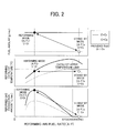
- FIG. 2 shows relationships of the fuel amount, reforming catalyst temperature, and reformed gas production amount relative to the reforming air/fuel ratio (A/F) in the fuel reforming reaction by way of partial oxidation reaction.
- A/F reforming air/fuel ratio
- the material control means controls the reforming air/fuel ratio (A/F)s to be at least stoichiometric in the stand-by mode.
- the material control means controls the reforming air/fuel ratio (A/F)r to be less than stoichiometric in the reforming mode.
- the reforming air/fuel ratio (A/F)s of materials is controlled to be at least stoichiometric in the stand-by mode, and the reforming air/fuel ratio (A/F)r of materials is controlled to be less than stoichiometric in the reforming mode.
- the temperature of the reforming catalyst can be maintained at high temperature without causing reformed gas to be produced in the stand-by mode, and reformed gas can be efficiently produced and supplied in the reforming mode.
- stoichiometric indicates a stoichiometric ratio for the complete combustion reaction.
- the reformed gas production amount will change according to the reforming air/fuel ratio (A/F) of materials supplied to the reforming catalyst. Therefore, it has a property whereby reforming gas will not be produced if the reforming air/fuel ratio (A/F) is at least stoichiometric. This is because, as the reforming air/fuel ratio (A/F) becomes small relative to stoichiometric, the partial oxidation reaction to produced reformed gas advances predominantly, whereas the complete oxidation reaction, which does not produce reformed gas, progresses predominantly as the reforming air/fuel ratio (A/F) becomes large relative to stoichiometric.
- the fuel amount in a case of having set the fuel amount to a constant, it also has a property whereby the amount of heat generated in the reforming reaction is greater in the complete oxidation reaction than the partial oxidation reaction.
- the present invention has applied these properties, and specifically, executes operation that can efficiently produce reformed gas by predominantly progressing the partial oxidation reaction in the reforming mode, with the reforming air/fuel ratio (A/F) being less than stoichiometric.
- the reforming catalyst includes: at least one type of metal catalyst component selected from the group consisting of rhodium, platinum, palladium, nickel, and cobalt; and at least one type of oxide selected from the group consisting of ceria, zirconia, alumina, and titania or a complex oxide with these as a base composition.
- metal catalyst component selected from the group consisting of rhodium, platinum, palladium, nickel, and cobalt
- oxide selected from the group consisting of ceria, zirconia, alumina, and titania or a complex oxide with these as a base composition.
- a catalyst produced with at least one type of metal catalyst component selected from the group consisting of rhodium, platinum, palladium, nickel, and cobalt, and at least one type of oxide selected from the group consisting of ceria, zirconia, alumina, and titania or a complex oxide with these as a base composition is used as the reforming catalyst.
- the activation start temperature being no higher than 300°C
- the partial oxidation reaction activity being high in the reforming mode
- the complete oxidation reaction activity being high in the stand-by mode
- thermal degradation being small relative to the application temperature up to 1200°C, etc.
- the activation start temperature will be high at 300°C or higher, a result of which more time will be required for mode transition, and the catalytic activity itself will be low, a result of which sufficient reformed gas will not be produced in the reforming mode, and thus a high temperature will not be able to be maintained in the stand-by mode, which is not preferable.
- the fuel reforming device is used for supplying the reformed gas to an exhaust system of an internal combustion engine.
- the operation control means includes a mode switching period determination means for determining the switching period of each of the modes based on operational information of the internal combustion engine.
- the fuel reforming device is used for supplying reformed gas to the exhaust system of an internal combustion engine, and is provided with a mode switching period determination means for determining the switching period of each of the modes of the stop mode, reforming mode, and stand-by mode, based on operational information of the internal combustion engine.
- a mode switching period determination means for determining the switching period of each of the modes of the stop mode, reforming mode, and stand-by mode, based on operational information of the internal combustion engine.
- reformed gas can be responsively produced and supplied synchronously with the NOx emission period of the internal combustion engine.
- operational information of the internal combustion engine the engine revolution speed, fuel injection amount, exhaust air/fuel ratio (A/F), intake air amount, exhaust purification catalyst temperature, etc. can be exemplified. From this operational information, the NOx emission behavior of the internal combustion engine is estimated, and the switching period of the operation modes is determined.
- the NOx occlusion and adsorption catalyst as an exhaust purification catalyst by disposing in the exhaust system, since the NOx occlusion and adsorption amount has dependence on the temperature of the exhaust purification catalyst, it is preferable to determine the mode switching period based on the temperature information of the exhaust purification catalyst.
- FIG. 3 is a block diagram of a fuel reforming device 10 according to the embodiment of the present invention.
- the fuel reforming device 10 according to the present embodiment is provided with a material supply unit 11 as a material supply means, a reforming unit 12 as a reforming means, a catalyst temperature sensor 13 as a catalyst temperature detection means, and an ECU (electronic control unit) 14.
- a material supply unit 11 as a material supply means
- a reforming unit 12 as a reforming means
- a catalyst temperature sensor 13 as a catalyst temperature detection means
- ECU electronic control unit
- the fuel used in the present embodiment is not particularly limited to gasoline, diesel, or the like, so long as it contains hydrocarbons.
- a fuel containing a great amount of heavy hydrocarbons is used, and more preferably, diesel is used.
- the material supply unit 11 may be anything capable of supplying materials composed of air and fuel to the reforming unit 12, and is configured by a fuel supply unit 11a, an air supply unit 11b, a mixing unit 11c, and the like.
- the material supply unit 11 configured by these is electrically connected by the ECU 14, and the fuel amount, air amount, and reforming air/fuel ratio (A/F) are controlled by the ECU 14 through the fuel supply unit 11a, air supply unit 11b, and mixing unit 11c.
- the fuel supply unit 11a may be provided with a fuel passage through which fuel flows, a fuel supply valve in which the valve-open time and valve-closed time are controlled by the ECU 14, and an injector that injects the fuel flowing in the fuel passage.
- the fuel passage has one end connected to a fuel tank, and another end connected to the injector.
- the fuel passage leads fuel stored in the fuel tank to the injector from the fuel tank.
- the injector injects fuel flowing through the fuel passage into the mixing unit 11c. The fuel thus injected is vaporized inside the mixing unit 11c, and is mixed uniformly with air.
- the air supply unit 11b may be provided with an air passage through which air flows, an air supply valve in which the valve-open time and valve-closed time are controlled by the ECU 14, and a suction pump that aspirates air and leads it into the mixing unit 11c by making the pressure inside of this air passage to be negative pressure.
- One end of the air passage 12a is connected to an air filter, and the other end is connected to the mixing unit 11c.
- mixing unit 11c mixed gas in which fuel supplied from the fuel supply unit 11a and air supplied from the air supply unit 11b is uniformly mixed is produced.
- the mixed gas thus mixed inside the mixing unit 11c is led into the reforming unit 12.
- the reforming unit 12 is provided with a reforming catalyst.
- the materials supplied from the material supply unit 11 are reformed by way of a reforming reaction by the action of the reforming catalyst, and are converted to reformed gas containing hydrogen and carbon monoxide.
- the reforming catalyst is not particularly restricted, and a conventionally known reforming catalyst can be used. More specifically, it is preferable to use a reforming catalyst that includes at least one type of a metal catalyst component selected from the group consisting of rhodium, platinum, palladium, nickel, and cobalt, and at least one type of oxide selected from the group consisting of ceria, zirconia, alumina, and titania, or a complex oxide with these as a base composition. These reforming catalysts are preferably used by loading on a honeycomb structure made of cordierite.
- the catalyst temperature sensor 13 can detect the temperature of the reforming catalyst, a conventionally known temperature sensor can be used.
- the catalyst temperature sensor 13 is electrically connected by the ECU 14, and signals detected by the catalyst temperature sensor 13 are supplied to the ECU 14.
- the ECU 14 is provided with an input circuit having functions of shaping input signal waveforms from various sensors, correcting the voltage levels to predetermined levels, converting analogy signal values to digital signal values, etc., and a central processing unit (hereinafter referred to as "CPU").
- the ECU 14 is provided with a memory circuit that stores various operational programs executed by the CPU, calculation results, etc., and an output circuit that outputs control signals to the material supply unit 11, reforming unit 12, and the like.
- the ECU 14 is configured by an operation control means for controlling operation of the fuel reforming device 10, and the like.
- the operation control means is configured to be able to execute operations of a stop mode that stops driving of the material supply unit 11 and causes the production of the reformed gas to stop, a reforming mode that causes the material supply unit 11 to be driven and the reformed gas to be produced, and a stand-by mode that makes quick transition to the reforming mode possible by maintaining a temperature of the reforming catalyst to within a predetermined range without driving the material supply unit 11 and with causing the reformed gas to be minimally produced.
- the operation control means controls the highest temperature of the reforming catalyst to within a range of 300°C to 1200°C during operation of the stand-by mode and during transition between modes of the stand-by mode and the reforming mode.
- the operation control means is provided with a material control means for controlling the air amount, fuel amount, and air/fuel ratio of materials supplied by the material supply unit 11.
- the operation control means is further provided with a mode switching period determination means for determining the switching period of each mode based on operational information of the internal combustion engine.
- the fuel reforming device 10 due to having a stand-by mode in which materials are supplied to the reforming catalyst, allowing for quick transition to the reforming mode by maintaining catalyst to within a predetermined range with causing the reformed gas to be minimally produced, the reforming mode can be transitioned to instantly without requiring time until the reforming catalyst is activated, when switching to the reforming mode.
- reformed gas can be responsively produced and supplied synchronously with an emission period of NOx, for example, without causing the reforming catalyst to thermally degrade, by controlling the highest temperature of the reforming catalyst to operate within a range of 300°C to 1200°C.
- the status of the reforming reaction can be accurately found by controlling the air amount, fuel amount, and reforming air/fuel ratio (A/F) of materials supplied to the reforming catalyst, based on the temperature of the reforming catalyst detected by the catalyst temperature sensor 13, a result of which the temperature of the reforming catalyst can be reliably maintained to within a predetermined range without causing reformed gas to be produced, and thus the reforming mode can be quickly transition to. Additionally, since the temperature of the reforming catalyst, the reaction status, and the like can be accurately found from the fluctuation of the material supply amounts during mode transition, transition between modes can be performed quickly and safely.
- A/F reforming air/fuel ratio
- the fuel reforming device 10 relating to the present embodiment, it is possible to prevent degrading of the catalyst due to being exposed to extremely high temperatures, and coke from forming, by way of controlling the air amount, fuel amount, and reforming air/fuel ratio (A/F) of materials so that the reforming air/fuel ratio (A/F)s and fuel amount (C)s of material supplied by the material supply unit 11 in the stand-by mode satisfy relationships of the above-mentioned formulas (1) and (2) relative to the reforming air/fuel ratio (A/F)r and fuel amount (C)r of materials supplied by the material supply unit 11 in the reforming mode.
- the optimum temperature in the reforming reaction can be maintained without causing reformed gas to be produced, and thus the stand-by mode can be reliably executed.
- reforming gas can be efficiently produced by predominantly progressing the partial oxidation reaction in the reforming mode, whereas the complete oxidation reaction progresses more predominantly in the stand-by mode, whereby an amount of heat for maintaining the reforming catalyst at a high temperature can be generated efficiently without causing reformed gas to be produced.
- the switching between each mode of the stop mode, reforming mode, and stand-by mode can be determined based on operational information of the internal combustion engine; therefore, reformed gas can be responsively produced and supplied synchronously with a NOx emission period of the internal combustion engine, for example.
- the effects of the present invention are notably exhibited by supplying reformed gas produced by the fuel reforming device 10 according to the present embodiment, upstream of a NOx purification catalyst disposed in the exhaust system of an internal combustion engine that is controlled to be lean or rich.
- a slurry was prepared by weighing raw material powders so that rhodium relative to ceria was 1% by mass ratio, then placing in a ball mill along with an aqueous medium, and agitating and mixing.
- a reforming catalyst of 1% Rh/CeO 2 by mass was prepared by coating the slurry thus obtained on a 50-cc carrier made of metal at 100 g/L, then performing drying and calcining for 2 hours at 600°C.
- the reforming catalyst thus prepared was filled into a reforming vessel, and a reforming test was conducted.
- the reforming test was performed by separating the operating conditions of the reforming vessel into three stages. More specifically, in Example 1, a reforming test was conducted by sequentially employing the (1) reforming mode, (2) stand-by mode, and (3) reforming mode as the operation mode of the reforming vessel. In addition, in Comparative Example 1, the reforming test was conducted by sequentially employing the (1) reforming mode, (2) stop mode, and (3) reforming mode, and in Comparative Example 2, by sequentially employing the (1) reforming mode, (2) reforming mode, and (3) reforming mode. It should be noted that the air amount and fuel amount of materials in each operation mode were as follows.
- the reforming tests were conducted at the above-mentioned conditions, and the amount of fuel used in mode (2), hydrogen production amount in mode (2), reforming catalyst temperature during transition from mode (2) to mode (3), and the time required to produce hydrogen again in mode (3) were each measured.
- the hydrogen production amount was measured using a mass spectrometer made by Pfeiffer Vacuum Inc.
- Table 1 The test conditions and test results for the Example and each Comparative Example are shown in Table 1.
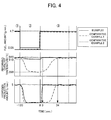
- time courses of the fuel amount, reforming catalyst temperature, and hydrogen production amount for the Example and each Comparative Example are shown in FIG. 4 .
- the hydrogen production amount in the stand-by mode is approximately 0, and thus it was recognized that no reformed gas was produced either.
- the fuel amount in the stand-by mode of Example 1 was 0.05 g/min, which is approximately 1/100 the fuel amount of the reforming mode of Comparative Example 2. From this it could be recognized that, by setting the reforming air/fuel ratio (A/F) in the stand-by mode to at least 1, the amount of fuel used could be curbed relative to continuing supplying reformed gas in the reforming mode. Therefore, the effects of the present invention have been demonstrated by the present test results.
Landscapes
- Chemical & Material Sciences (AREA)
- Engineering & Computer Science (AREA)
- Combustion & Propulsion (AREA)
- Chemical Kinetics & Catalysis (AREA)
- General Engineering & Computer Science (AREA)
- Organic Chemistry (AREA)
- Mechanical Engineering (AREA)
- General Health & Medical Sciences (AREA)
- Inorganic Chemistry (AREA)
- Health & Medical Sciences (AREA)
- Hydrogen, Water And Hydrids (AREA)
- Exhaust Gas After Treatment (AREA)
- Exhaust Gas Treatment By Means Of Catalyst (AREA)
Applications Claiming Priority (2)
| Application Number | Priority Date | Filing Date | Title |
|---|---|---|---|
| JP2008038611A JP5149647B2 (ja) | 2008-02-20 | 2008-02-20 | 燃料改質装置 |
| PCT/JP2009/053026 WO2009104735A1 (ja) | 2008-02-20 | 2009-02-20 | 燃料改質装置 |
Publications (2)
| Publication Number | Publication Date |
|---|---|
| EP2248764A1 true EP2248764A1 (de) | 2010-11-10 |
| EP2248764A4 EP2248764A4 (de) | 2011-03-09 |
Family
ID=40985612
Family Applications (1)
| Application Number | Title | Priority Date | Filing Date |
|---|---|---|---|
| EP09711863A Ceased EP2248764A4 (de) | 2008-02-20 | 2009-02-20 | Brennstoffreformierungsvorrichtung |
Country Status (4)
| Country | Link |
|---|---|
| US (1) | US8500832B2 (de) |
| EP (1) | EP2248764A4 (de) |
| JP (1) | JP5149647B2 (de) |
| WO (1) | WO2009104735A1 (de) |
Families Citing this family (3)
| Publication number | Priority date | Publication date | Assignee | Title |
|---|---|---|---|---|
| US9178235B2 (en) * | 2009-09-04 | 2015-11-03 | Lg Fuel Cell Systems, Inc. | Reducing gas generators and methods for generating a reducing gas |
| JP6090136B2 (ja) * | 2013-12-05 | 2017-03-08 | 株式会社デンソー | 還元剤添加装置 |
| JP2023031006A (ja) | 2021-08-24 | 2023-03-08 | 株式会社デンソー | 触媒構造体、燃料改質方法および燃料改質システム |
Family Cites Families (17)
| Publication number | Priority date | Publication date | Assignee | Title |
|---|---|---|---|---|
| JP2600492B2 (ja) | 1991-10-03 | 1997-04-16 | トヨタ自動車株式会社 | 内燃機関の排気浄化装置 |
| CA2097609C (en) * | 1991-10-03 | 1999-03-16 | Shinichi Takeshima | Device for purifying exhaust of internal combustion engine |
| EP0597106B1 (de) * | 1991-10-14 | 1997-04-02 | Toyota Jidosha Kabushiki Kaisha | Abgasreinigungsanlage für brennkraftmaschinen |
| JPH1179703A (ja) * | 1997-09-04 | 1999-03-23 | Aisin Seiki Co Ltd | 燃料電池用改質装置 |
| JP3642273B2 (ja) | 1999-10-21 | 2005-04-27 | 日産自動車株式会社 | 排気ガス浄化システム |
| JP3685052B2 (ja) * | 2000-11-30 | 2005-08-17 | 日産自動車株式会社 | 内燃機関の排気浄化装置 |
| JP3738689B2 (ja) * | 2000-12-12 | 2006-01-25 | 日産自動車株式会社 | 燃料改質器の温度制御方法 |
| JP3740987B2 (ja) * | 2001-02-08 | 2006-02-01 | 日産自動車株式会社 | 内燃機関の排気浄化装置 |
| JP2003128401A (ja) * | 2001-10-19 | 2003-05-08 | Fuji Electric Co Ltd | 水素発生装置とその運転方法 |
| US7082753B2 (en) | 2001-12-03 | 2006-08-01 | Catalytica Energy Systems, Inc. | System and methods for improved emission control of internal combustion engines using pulsed fuel flow |
| ATE387571T1 (de) * | 2001-12-03 | 2008-03-15 | Eaton Corp | System und verfahren zur verbesserten emissionskontrolle von brennkraftmaschinen |
| EP1563169A1 (de) | 2002-11-15 | 2005-08-17 | Catalytica Energy Systems, Inc. | Vorrichtung und methode zur reduktion der nox-emissionen in einem magermotor |
| JP4457559B2 (ja) * | 2003-01-09 | 2010-04-28 | 日産自動車株式会社 | 燃料蒸発装置 |
| US6964156B2 (en) | 2003-10-23 | 2005-11-15 | Hydrogensource Llc | Intermittent application of syngas to NOx trap and/or diesel engine |
| JP2006242020A (ja) | 2005-03-01 | 2006-09-14 | Hino Motors Ltd | 排気浄化装置 |
| JP4778858B2 (ja) | 2006-08-01 | 2011-09-21 | 本田技研工業株式会社 | 気化器の残存燃料自動抜取装置 |
| JP5015025B2 (ja) | 2008-02-13 | 2012-08-29 | 本田技研工業株式会社 | 燃料改質器の制御装置 |
-
2008
- 2008-02-20 JP JP2008038611A patent/JP5149647B2/ja not_active Expired - Fee Related
-
2009
- 2009-02-20 US US12/867,880 patent/US8500832B2/en not_active Expired - Fee Related
- 2009-02-20 EP EP09711863A patent/EP2248764A4/de not_active Ceased
- 2009-02-20 WO PCT/JP2009/053026 patent/WO2009104735A1/ja not_active Ceased
Also Published As
| Publication number | Publication date |
|---|---|
| WO2009104735A1 (ja) | 2009-08-27 |
| JP2009196837A (ja) | 2009-09-03 |
| US20100316532A1 (en) | 2010-12-16 |
| EP2248764A4 (de) | 2011-03-09 |
| US8500832B2 (en) | 2013-08-06 |
| JP5149647B2 (ja) | 2013-02-20 |
Similar Documents
| Publication | Publication Date | Title |
|---|---|---|
| EP2233711B1 (de) | Abgasreinigungsvorrichtung für einen verbrennungsmotor | |
| EP2246535B1 (de) | Abgasreinigungsvorrichtung für einen verbrennungsmotor | |
| US9810120B2 (en) | Exhaust gas purifying system | |
| CN103157516B (zh) | 排气净化用催化剂 | |
| EP2246534B1 (de) | Abgasreinigungsvorrichtung für einen verbrennungsmotor | |
| EP1904724B1 (de) | Verfahren, vorrichtung und computerprogrammprodukt zur diagnose mindestens einer abgasemissionssteuereinheit | |
| US8944037B2 (en) | Exhaust gas purifying apparatus for internal combustion engine | |
| US8413426B2 (en) | Method of exhaust cleaning for internal combustion engine and exhaust cleaner | |
| EP1313934B1 (de) | Abgassystem für brennkraftmaschinen mit magergemischverbrennung | |
| US10184374B2 (en) | Apparatus and method for desulfation of a catalyst used in a lean burn methane source fueled combustion system | |
| EP1925789A1 (de) | Abgasreinigungssystem für einen verbrennungsmotor | |
| EP2233712A1 (de) | Abgasreiniger für einen verbrennungsmotor | |
| US9599002B2 (en) | Engine control method for maintaining performance of oxidation catalyst | |
| EP2098699A1 (de) | Abgasreinigungsvorrichtung für brennkraftmotor | |
| JP2009264285A (ja) | 内燃機関の排気ガス浄化装置 | |
| EP1989412B1 (de) | Abgassystem für einen verbrennungsmotor mit fremdzündung | |
| US8500832B2 (en) | Fuel reforming device | |
| JP2010270664A (ja) | 内燃機関の排気浄化システム | |
| JP2019203487A (ja) | 燃料改質装置及びその制御方法 | |
| US9038372B2 (en) | Exhaust purification system of internal combustion engine | |
| JP2007113497A (ja) | 内燃機関の排気浄化装置 | |
| CN101495725A (zh) | 在具有主要在贫条件下操作的内燃机的机动车中车载再活化热陈化的氮氧化物储存催化剂的方法 | |
| JP2009041422A (ja) | 排気ガス浄化装置 | |
| JP2010138802A (ja) | 内燃機関の排気浄化装置 |
Legal Events
| Date | Code | Title | Description |
|---|---|---|---|
| PUAI | Public reference made under article 153(3) epc to a published international application that has entered the european phase |
Free format text: ORIGINAL CODE: 0009012 |
|
| 17P | Request for examination filed |
Effective date: 20100823 |
|
| AK | Designated contracting states |
Kind code of ref document: A1 Designated state(s): AT BE BG CH CY CZ DE DK EE ES FI FR GB GR HR HU IE IS IT LI LT LU LV MC MK MT NL NO PL PT RO SE SI SK TR |
|
| AX | Request for extension of the european patent |
Extension state: AL BA RS |
|
| A4 | Supplementary search report drawn up and despatched |
Effective date: 20110204 |
|
| DAX | Request for extension of the european patent (deleted) | ||
| 17Q | First examination report despatched |
Effective date: 20111102 |
|
| REG | Reference to a national code |
Ref country code: DE Ref legal event code: R003 |
|
| STAA | Information on the status of an ep patent application or granted ep patent |
Free format text: STATUS: THE APPLICATION HAS BEEN REFUSED |
|
| 18R | Application refused |
Effective date: 20130620 |