EP2248980A1 - Volet pliant coulissant - Google Patents
Volet pliant coulissant Download PDFInfo
- Publication number
- EP2248980A1 EP2248980A1 EP09159626A EP09159626A EP2248980A1 EP 2248980 A1 EP2248980 A1 EP 2248980A1 EP 09159626 A EP09159626 A EP 09159626A EP 09159626 A EP09159626 A EP 09159626A EP 2248980 A1 EP2248980 A1 EP 2248980A1
- Authority
- EP
- European Patent Office
- Prior art keywords
- main
- engagement
- loading element
- axis
- shutter
- Prior art date
- Legal status (The legal status is an assumption and is not a legal conclusion. Google has not performed a legal analysis and makes no representation as to the accuracy of the status listed.)
- Granted
Links
Images


Classifications
-
- E—FIXED CONSTRUCTIONS
- E06—DOORS, WINDOWS, SHUTTERS, OR ROLLER BLINDS IN GENERAL; LADDERS
- E06B—FIXED OR MOVABLE CLOSURES FOR OPENINGS IN BUILDINGS, VEHICLES, FENCES OR LIKE ENCLOSURES IN GENERAL, e.g. DOORS, WINDOWS, BLINDS, GATES
- E06B9/00—Screening or protective devices for wall or similar openings, with or without operating or securing mechanisms; Closures of similar construction
- E06B9/02—Shutters, movable grilles, or other safety closing devices, e.g. against burglary
- E06B9/06—Shutters, movable grilles, or other safety closing devices, e.g. against burglary collapsible or foldable, e.g. of the bellows or lazy-tongs type
- E06B9/0607—Shutters, movable grilles, or other safety closing devices, e.g. against burglary collapsible or foldable, e.g. of the bellows or lazy-tongs type comprising a plurality of similar rigid closing elements movable to a storage position
- E06B9/0646—Shutters, movable grilles, or other safety closing devices, e.g. against burglary collapsible or foldable, e.g. of the bellows or lazy-tongs type comprising a plurality of similar rigid closing elements movable to a storage position characterised by the relative arrangement of the closing elements in the stored position
- E06B9/0676—Shutters, movable grilles, or other safety closing devices, e.g. against burglary collapsible or foldable, e.g. of the bellows or lazy-tongs type comprising a plurality of similar rigid closing elements movable to a storage position characterised by the relative arrangement of the closing elements in the stored position stored in a stacked configuration
-
- E—FIXED CONSTRUCTIONS
- E05—LOCKS; KEYS; WINDOW OR DOOR FITTINGS; SAFES
- E05F—DEVICES FOR MOVING WINGS INTO OPEN OR CLOSED POSITION; CHECKS FOR WINGS; WING FITTINGS NOT OTHERWISE PROVIDED FOR, CONCERNED WITH THE FUNCTIONING OF THE WING
- E05F15/00—Power-operated mechanisms for wings
- E05F15/60—Power-operated mechanisms for wings using electrical actuators
- E05F15/603—Power-operated mechanisms for wings using electrical actuators using rotary electromotors
- E05F15/605—Power-operated mechanisms for wings using electrical actuators using rotary electromotors for folding wings
-
- E—FIXED CONSTRUCTIONS
- E06—DOORS, WINDOWS, SHUTTERS, OR ROLLER BLINDS IN GENERAL; LADDERS
- E06B—FIXED OR MOVABLE CLOSURES FOR OPENINGS IN BUILDINGS, VEHICLES, FENCES OR LIKE ENCLOSURES IN GENERAL, e.g. DOORS, WINDOWS, BLINDS, GATES
- E06B9/00—Screening or protective devices for wall or similar openings, with or without operating or securing mechanisms; Closures of similar construction
- E06B9/02—Shutters, movable grilles, or other safety closing devices, e.g. against burglary
- E06B9/06—Shutters, movable grilles, or other safety closing devices, e.g. against burglary collapsible or foldable, e.g. of the bellows or lazy-tongs type
- E06B9/0607—Shutters, movable grilles, or other safety closing devices, e.g. against burglary collapsible or foldable, e.g. of the bellows or lazy-tongs type comprising a plurality of similar rigid closing elements movable to a storage position
- E06B9/0615—Shutters, movable grilles, or other safety closing devices, e.g. against burglary collapsible or foldable, e.g. of the bellows or lazy-tongs type comprising a plurality of similar rigid closing elements movable to a storage position characterised by the closing elements
- E06B9/0638—Slats or panels
-
- E—FIXED CONSTRUCTIONS
- E06—DOORS, WINDOWS, SHUTTERS, OR ROLLER BLINDS IN GENERAL; LADDERS
- E06B—FIXED OR MOVABLE CLOSURES FOR OPENINGS IN BUILDINGS, VEHICLES, FENCES OR LIKE ENCLOSURES IN GENERAL, e.g. DOORS, WINDOWS, BLINDS, GATES
- E06B9/00—Screening or protective devices for wall or similar openings, with or without operating or securing mechanisms; Closures of similar construction
- E06B9/02—Shutters, movable grilles, or other safety closing devices, e.g. against burglary
- E06B9/06—Shutters, movable grilles, or other safety closing devices, e.g. against burglary collapsible or foldable, e.g. of the bellows or lazy-tongs type
- E06B9/0607—Shutters, movable grilles, or other safety closing devices, e.g. against burglary collapsible or foldable, e.g. of the bellows or lazy-tongs type comprising a plurality of similar rigid closing elements movable to a storage position
- E06B9/0646—Shutters, movable grilles, or other safety closing devices, e.g. against burglary collapsible or foldable, e.g. of the bellows or lazy-tongs type comprising a plurality of similar rigid closing elements movable to a storage position characterised by the relative arrangement of the closing elements in the stored position
- E06B9/0669—Shutters, movable grilles, or other safety closing devices, e.g. against burglary collapsible or foldable, e.g. of the bellows or lazy-tongs type comprising a plurality of similar rigid closing elements movable to a storage position characterised by the relative arrangement of the closing elements in the stored position stored in a zig-zag arrangement
-
- E—FIXED CONSTRUCTIONS
- E05—LOCKS; KEYS; WINDOW OR DOOR FITTINGS; SAFES
- E05Y—INDEXING SCHEME ASSOCIATED WITH SUBCLASSES E05D AND E05F, RELATING TO CONSTRUCTION ELEMENTS, ELECTRIC CONTROL, POWER SUPPLY, POWER SIGNAL OR TRANSMISSION, USER INTERFACES, MOUNTING OR COUPLING, DETAILS, ACCESSORIES, AUXILIARY OPERATIONS NOT OTHERWISE PROVIDED FOR, APPLICATION THEREOF
- E05Y2900/00—Application of doors, windows, wings or fittings thereof
- E05Y2900/10—Application of doors, windows, wings or fittings thereof for buildings or parts thereof
- E05Y2900/13—Type of wing
- E05Y2900/146—Shutters
Definitions
- the invention relates to a sliding folding shutter for closing and releasing at least a part of a building opening, in particular a window or a door, in particular for sun protection, according to the preamble of claim 1.
- sliding folding shops of the type mentioned in two, four or Mogliger execution are known from the prior art. They are used in particular as sun and sight protection or in a more massive embodiment as burglary and storm protection in front of windows and doors.
- Such sliding folding shops usually have at least two, preferably four or more loading elements, which are each connected to each other articulated.
- a sliding folding shutter is composed of one or more whole or half pairs of shutter elements, each pair forming three vertical axes, namely a middle minor axis representing the central pivotal connection axis of the two shutter elements, and two peripheral main axes. All main axes lie in one plane, namely the closing plane.
- the first main axis of the first store element pair is usually immovable and, for example, pivotally fixed to the window frame.
- the rest of the main axes are guided linearly displaceable along a horizontal and perpendicular to the main axes extending locking axis, wherein the store element pairs are pivotally connected to each other about the two adjacent and considered as common main axes.
- the store elements, apart from the marginal first shop element, which is mounted only pivotable, but not displaceable, in addition to their respective window or door opening facing edge sides parallel to the closing plane slidably stored in at least one horizontal longitudinal guide rail.
- the free and last main axis is used to open and close the store and is coupled with adjustment means, such as a belt or cable, which is either manually or preferably electrically driven, for linear adjustment.
- a folding door is known in which between the wings a spring arrangement is disclosed.
- a spring arrangement is disclosed.
- One Disadvantage of such a spring arrangement is that the springs counteract the drive when closing, reaching the dead center due to the spring force and the limited driving force is prevented even in the closed state, the drive is subject to increased wear and the springs themselves also subject to wear.
- the arrangement of springs is not always feasible for reasons of space.
- WO 2004/074616 A1 is a leaflet gate with a drive device for opening and closing known, wherein a pivotable by a drive motor about a vertical axis pivoted lever cooperates with the first wing member.
- a drive device has a pivotable about a vertical pivot axis of a drive motor between an open and a closed position pivot lever which cooperates with the first shutter member for pivoting thereof between its open and closed position.
- the drive device comprises a pivotable by a further drive motor between an open and a closed position about a vertical pivot axis additional pivot lever, which cooperates with the third loading element for pivoting thereof between its open and closed position. Since the pivot lever act directly on the shutter elements in non-parallel, substantially perpendicular direction to the closing plane, the dead center of the Store elements are overcome to each other, so that the store elements in the closed state of the store can be aligned with each other.
- a disadvantage of such a pivot lever drive is in particular that for each pair of store elements a separate pivot lever drive is provided and the existence of obvious and environmental influences suspended pivot lever is not always able to meet both aesthetic and functional requirements.
- the object of the invention is therefore to provide a sliding folding store of the type mentioned above, which has a simple and largely integrated into the sliding folding store drive and its loading elements in the closed state of the sliding folding store have an alignment in a common plane.
- the invention is based on aligning at least one pair of store elements in its closed position in the dead center or over-center position, the first store element and the second store element being flat or parallel to the closing plane, and an engaging unit located in the peripheral area of the push-fold store extending horizontal frame is arranged and with an engaging arm, which is pivotable about a pivot axis by means of an engagement motor to overcome the dead center alignment area.
- the further opening the pair of store takes place by a linear displacement of a main guide member by means of a main drive, the pair of stores from the edge region of Tot Vietnameseausses Symposium in which the pair of shops unfolded and hinged to the closing plane, in a first open position in which the pair of shops folded accordion-like and pivoted away from the closing plane, is pivotable.
- the closing takes place in reverse order.
- the sliding folding shutter comprises a control unit which is in operative connection with the main drive, the engagement motor and detection means for detecting the position of the pair of trays in the dead center alignment area and is designed such that an opening sequence and a closing sequence can be executed when the pair of trays are closed.
- the opening sequence when the loading pair is closed - the engagement unit for pivoting the pair of trays is actuated out of the dead-center alignment area.
- the main drive is driven to linearly displace the main guide member in the direction of the fixed main axis of the pair of trays and into the first open position.
- the store pair is guided such that it is in its closed position in a Studentstot Vietnameseausrhythm.
- a extended opening sequence are used in which the main drive is first controlled for linear displacement of the main guide member in the direction away from the fixed main axis of the pair of trays to overcome the Kochtot Vietnameseausrhythm and to achieve an absolute dead center of the pair of trays.
- the engagement unit is now activated for pivoting the pair of stores out of the absolute dead center alignment and the dead center alignment area.
- the main drive for linear displacement of the main guide member is driven in the direction of the fixed main axis in the open position.
- the main drive and the engagement unit cooperate in such a way that the main drive in the pivot range of the store pair outside the dead center alignment area takes over the opening and closing of the store pair by the linear displacement of the main guide member, whereas the engagement unit, the pivoting of the store pair within the dead center and beyond in this allows by means of a pivoting movement.
- the invention thus makes it possible to realize a just-oriented in the closed state and located in dead center or even in Kochtot Vietnameseauscardi sliding folding store, with disturbing and visually striking additional elements, which adversely affect the aesthetics of the sliding folding store and the susceptibility increase, can be waived.
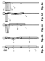
- FIGS. 1 to 4e show a common embodiment, which is why the mating figures are described in part together and to the re-explanation of already introduced features and reference numerals is omitted.
- illustrations are schematic illustrations, wherein the proportions of the individual elements have been deliberately changed to improve the visibility of certain features.
- a large thickness of the store elements was selected for better visibility of the side edges.
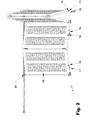
- FIGS. 1 and 2 and FIGS. 3 to 4e show, in a schematic side or oblique view and top view, respectively, a sliding folding shutter 1 for closing and releasing at least part of a building opening, in particular a window or a door.
- the sliding folding shutter 1 can be used in particular for sun or privacy or for wind and weather protection and burglary protection.
- the sliding folding shutter 1 has a first loading element 10, which is pivotally mounted in the region of its first side edge 11 about an immovable vertical first main axis 51, which lies in a vertically extending closing plane 3, as in FIG. 3 shown.
- the first Main axis 51 is - as the other main axes - to be understood as a geometric axis.
- it may also be a mechanical axis, for example the pin of a hinge attached to the second side edge 11.
- the first main axis 51 forms the pivotable connection between the first loading element 10 and the frame of the building opening, for example the window frame.
- a second loading element 20 is pivotally connected to the first loading element 10 in the region of its second side edge 12 about a vertical first secondary axis 61.
- the minor axes are geometric axes, but they can also be formed by physical axes, in particular hinge elements, as in the FIGS. 1 and 2 recognizable.
- the second loading element 20 is in turn pivotally mounted in the region of its first side wheel 21 about a displaceable vertical second main axis 52 which lies in the closing plane 3.
- the second main axis 52 is guided linearly displaceable along a perpendicular to the vertical second main axis 52 and in the closing plane 3 horizontal locking axis 4 by means of a first main guide member.
- the first main axis 51 and the second main axis 52 are parallel and lie in the vertically extending shooting plane 3, wherein the distance of the two parallel main axes 51 and 52 can be changed by moving the second main axis 52 in the direction of the locking axis 4.
- the first main guide member 56 is arranged in the region of the second main axis 52, in particular on the upper and / or lower edge of the second loading element 20.
- the second main axis 52 passes substantially through the main guide member 56, which is why in the plan view of FIGS. 3 to 4e the first main guide member 56 is not graphically separable from the second major axis 52.
- the first main guide member 56 is for example a first runner within the main guide rail 80, which allows only a movement parallel to the locking axis 4 and around the vertical second main axis 52 around.
- a main drive 81 is directly or indirectly coupled to the first main guide member 56 such that the first main guide member 56 can be displaced linearly along the closing axis 4.
- the coupling can take place directly, for example by means of a belt drive within the main guide rail 80, or indirectly, for example by another, in particular third loading element 30 and / or fourth loading element 40, which is directly or indirectly connected to the second loading element 20, adjustable by means of the main drive 81 is and thus at stop the respective first store element 56 mitver reinstate the first main guide member 56, as in the embodiment shown the case.
- the invention also includes a sliding folding shutter with only two shutter elements 10 and 20, even though the illustrated embodiment has a total of four shutter elements 10, 20, 30 and 40.
- the third store element 30 and the fourth store element 40 described below and the features arranged there and associated with these store elements are optional features which represent a development of the invention.
- first shutter member 10 and the second shutter member 20 of a in the Figures 3 . 4d and 4e 1, in which the first loading element 10 and the second loading element 20 are folded like an accordion and respectively pivoted away from the closing plane 3, into an in FIG. 4a shown first closed position C1, in which the first loading element 10 and the second loading element 20 are unfolded and each hinged to the closing plane 3 to close and open in reverse order, as in Figures 4b and 4c shown.
- first closed position C1 of the two store elements 10 and 20 are selbige according to the invention in a Tot Vietnameseausrhythms Symposium.
- first loading element 10 and the second loading element 20 are each aligned substantially parallel to the closing plane 3.
- the store elements 10 and 20 are located in an over-center orientation, since the first main axis 51, the second main axis 52 and the first minor axis 61 are arranged such that the first minor axis 61 in the first closed position C1 and with parallel alignment of the first loading element 10 and the second loading element 20 to the closing plane 3 - extends outside the closing plane 3 on one side of the closing plane 3, and in the first open position O1 on the other side of the closing plane 3.
- the first minor axis 61 is in the first closed position C1, FIG. 4a on the one side of the closing plane 3 and in the first open position O1, Figures 3 and 4e , on the other side of the closing plane 3.
- the first minor axis 61 must therefore be guided through the closing levels 3 for opening and closing.
- the state in which the first minor axis 61 lies substantially in the closing plane 3, and thus the three axes 51, 52 and 61 all run in the closing plane 3, is referred to as absolute dead center orientation T, as in FIG. 4b shown, designated.
- the absolute dead center alignment T can be achieved by pulling the two main axes 51 and 52 apart and thus maximizing the spacing of the major axes 51 and 52, as in FIGS FIGS. 4a and 4b shown.
- this absolute dead center orientation T is surrounded by a region in which blocking of the loading elements 10 and 20 likewise takes place and folding is not possible by linear displacement.
- This area is called the dead center alignment area.
- the dead center alignment range is thus determined not only by the position of the minor axis to the closing plane, but also by friction in the joints and the hinge geometry.
- the dead point alignment area is that alignment area in which a close-up unfolded pair of store elements can not be accordion-folded by reducing the pitch of the two major axes due to the location of the minor axis relative to the two major axes.
- This dead center alignment area is formed on the one hand by the absolute dead center orientation T, the area surrounding this absolute dead center T, which results from friction, and a possible overcenter alignment area.
- the closed position and the absolute dead center alignment coincide or, as in the illustrated embodiment, they are apart, in particular with the over-center alignment area therebetween.
- the first loading element 10 and the second loading element 20 are each aligned essentially parallel to the closing plane 3 and are in over-center alignment, as in FIG FIG. 4a shown.
- the sliding folding shutter 1 has an engagement unit 70 for overcoming the dead center alignment area, which is arranged in the region of the first main axis 51.
- the engagement unit 70 is located on the horizontal frame 2, which is in the edge region of the sliding folding store 1 and the opening to be closed and parallel to the closing axis 4.
- the engagement unit 70 has an engagement arm 71, which is movable by means of an engagement motor 72, in particular pivotable about a pivot axis 73, as in FIG FIG. 1 shown.
- the rotational axis of the engagement motor 72 corresponds to the pivot axis 73 of the engagement arm 71.
- the engagement motor 72 can be formed, in particular, by a rotary drive or a linear drive, with optionally a deflecting member being used to generate a pivoting movement, a linear movement or another movement of the engagement arm 71, in particular around the engagement axis 73.
- an engagement stop 74 is disposed on the side facing the horizontal frame 2 side 13, as in FIG. 2 illustrated.
- the engagement stop 74 is an engagement bolt.
- the engagement stop 74 is in the mechanical working area of the engagement arm 71 so that the engagement arm 71 can exert a force on the engagement stop 74 to initiate movement of the first loading element 10.
- the engagement stop is designed as an engagement bolt 74 extending substantially parallel to the first main axis 51.
- it is also another embodiment, for example in the form of a nose, a hook or any other part that extends in the mechanical action region of the engagement arm 71, possible.
- the engagement unit 70 and the engagement stop 74 are arranged and configured such that the engagement stop 74 in the effective region by a forced by the engagement motor 72 moving, in the illustrated embodiment pivoting, the engagement arm 71 in a closing direction, in particular a closing pivot direction of the Engaging arm 71 in the first closed position C1, as in FIG. 4a is shown, can be pressed and by a particular opposite movement, in the illustrated embodiment pivoting, the engagement arm 71 in an opening direction, in particular an opening pivoting direction, of the engagement arm 71 from the dead center alignment area, FIGS. 4a and 4b , out and towards the first open position O1, Figures 4c, 4d and 4e , is depressible.
- the engagement unit 70 is formed such that the engagement arm 71 contacts the engagement stop 74 when moving in the closing direction on a side facing the first open position O1 and moving in the opening direction on an opposite side facing the first closed position C1 , In other words, the engagement arm 71 pivots about the engagement stop 74 and contacts it either from one side or the other.
- detecting means are provided, by means of which a position of the first loading element 10 in Tot Vietnameseausrhythms Symposium, as in the FIGS. 4a and 4b shown is detectable.
- a position of the first loading element 10 in the dead center alignment area is detected by the fact that the main drive 81 is blocked, since a linear displacement of the loading elements 10 and 20 is no longer possible.
- the store elements 10 and 20 are located, for example, in the first closed position C1 in FIG FIG.
- the detecting means for detecting the leaving of the dead center alignment area are accordingly in the illustrated embodiment as a means for detecting a driving force drop of the main drive 81, in particular as a current drop detection means on the main drive 81, is formed.
- the detection means may also be formed by other suitable means. They can be formed, for example, as a position sensor, microswitch, Hall sensor, light barrier, time switch, current detection means on the main drive or current detection means on the engagement motor. In particular, it is possible to detect the position of the store elements by a timekeeping. From the knowledge of the speed of movement of the main drive 81 and the starting position and the kinematics of the shutter elements 10 and 20, their position can be derived by timing.
- the sliding folding shutter 1 further comprises a control unit 90, FIG. 4a which is in operative connection with the main drive 81, the engagement motor 72 and the detection means and is designed such that in the first closed position C1, FIG. 4a , an opening sequence and at the first open position O1, Figures 4d and 4e , in particular an overall open position O of the sliding folding store 1, Figure 4e , a closing sequence is executable.
- a control unit 90 FIG. 4a which is in operative connection with the main drive 81, the engagement motor 72 and the detection means and is designed such that in the first closed position C1, FIG. 4a , an opening sequence and at the first open position O1, Figures 4d and 4e , in particular an overall open position O of the sliding folding store 1, Figure 4e , a closing sequence is executable.
- the engagement unit 70 turns out of the dead center alignment area for pivoting the first shutter 10.
- FIGS. 4a and 4b so that the two loading elements 10 and 20 leave the dead center alignment area and are displaceable by means of the main drive 81.
- the main drive 81 is actuated for direct or indirect linear displacement of the first main guide element 56 in the direction of the first main axis 51 into the first open position O1.
- Figures 4c and 4d in particular in an overall open position O of the sliding folding store 1, Figure 4e
- the closing sequence is at the first open position O1, Figures 4d and 4e , in particular an overall open position O of the sliding folding store 1, Figure 4e , executable.
- the main drive 81 is driven to directly or indirectly linearly displace the first main guide member 56 toward the first closed position C1 and away from the first main axis 51, as in FIG Figure 4c shown.
- the engagement unit 70 is actuated to pivot the first shutter element 10 into the first closed position C1, FIG. 4a possibly assisted by reversing the direction of the main drive 81.
- the control unit 90 is preferably an electronic controller electrically connected to the main drive 81, the engagement motor 72 and the detection means. If the detection means for detecting a position of the first shutter element 10 in the dead center alignment area, in particular in the absolute dead center, formed by current increase detection means on the main drive 81, the detection means may be integrated in the form of a current measuring device in the control unit. Instead of an electronic control unit 90 also a pneumatic, hydraulic or mechanical control is possible.
- the engagement unit 70, the engagement stop 74 and the control unit 90 are arranged and configured such that the engagement arm 71 is pivotable into a basic position pivoted away from the engagement stop 74 in such a way that the first loading element 10 is freely pivotable from the engagement unit 70 is like in the Figures 4c, 4d and 4e the case.
- the first main axis 51, the second main axis 52 and the first minor axis 61 are arranged such that the first minor axis 61 in the first closed position C1 and in parallel alignment of the first Store element 10 and the second loading element 20 to the closing plane 3 outside the closing plane 3 on the one side of the closing plane 3 and thus in the over-center position, FIG. 4a , and in the first open position O1 on the other side of the closing plane 3, Figures 4c, 4d and 4e runs.
- the control unit 90 is in this case in operative connection with the main drive 81, the engagement motor 72 and the detection means and is designed such that in the first closed position C1 an extended opening sequence can be executed.
- FIG. 4a Initially, the main drive 81 for direct or indirect linear displacement of the first main guide member 56 in the direction away from the first main axis 51 to overcome the Kochtot Vietnameseauscardi and to achieve an absolute dead center T of the first loading element 10 and the second loading element 20 is driven.
- the first loading element 10 is moved out of the absolute dead center alignment T and the dead center alignment area.
- This extended sequence is particularly advantageous in sliding folding shutter assemblies that are in the over centered overclock position, as is the case in the embodiment shown, because the engagement unit 70 is unloaded and only in a very small area, namely the area near the absolute dead center, must work.
- the described extended opening sequence it is also possible for the described extended opening sequence to be dispensed with even in the event of an over-center alignment loading and for the engagement unit 70 to also move the first loading element 10 in the over-center alignment area in the direction of absolute dead center alignment.
- the store elements 10 and 20 in the direction away from the first main axis 51 should have a corresponding clearance, so that an adjustment in the absolute dead center alignment is not prevented by the main drive 81.
- the sliding folding shutter 1 shown also has a third loading element 30 which is pivotally connected in the region of its first side edge 31 to the second loading element 20 in the region of its first side edge 21 about the displaceable vertical second main axis 52.
- a fourth loading element 40 is in the region of its second side edge 42 with the third Shop element 30 in the region of the second side edge 32 pivotally connected about a vertical second minor axis 62.
- the fourth shop element 40 is pivotably mounted in the region of its first side wheel 41 about a displaceable vertical third main axis 53 which lies in the closing plane 3.
- the third main axis 53 is linearly displaceably guided along the horizontal closing axis 4 perpendicular to the third main axis 53 and in the closing plane 3 by means of a second main guide element 57, in particular in the main guide rail 80, so that the horizontal distance between the second main axis 52 and the third main axis 53 is adjustable.
- the third main axis 53 passes through the second main guide member 57, which is why in plan view, FIG. 3 in that the second main guide member 56 is not graphically separable from the third main axis 53.
- the vertical main and minor axes 51, 52, 53, 61 and 62 are parallel to each other, the main axes 51, 52 and 53 are in the shooting planes 3.
- the main drive 81 is so directly or indirectly coupled, for example by means of a belt drive with the second main guide member 57, that the third shutter member 30 and the fourth shutter member 40 from a second open position 02, Figure 4e in which the third loading element 30 and the fourth loading element 40 are folded like an accordion and are respectively pivoted away from the closing plane 3, into a second closed position C2, Figures 4c, 4b and 4a in which the third loading element 30 and the fourth loading element 40 are unfolded and pivoted respectively to the closing plane 3, by direct or indirect linear displacement of the second main guide member 57 along the locking axis 4 in particular closed by means of the main drive 81 and in reverse order openable.
- the sliding folding shutter 1b is in this case designed such that it depends on an overall open position O, Figure 4e in the first open position O1 and second open position 02, so that the building opening is released, via an overall intermediate position I, FIGS. 4c and 4d , in the first open position O1 and second closed position C2, in an overall closed position C, FIG. 4a in the first closed position C1 and second closed position C2, so that the building opening is closed, can be closed by the linear displacement of the second main guide member 57 and opened in the reverse order.
- the third shutter member 30 and the fourth shutter member 40 are respectively aligned substantially parallel to the shutter plane 3.
- the third shutter member 30 and the fourth shutter member 40 are also in a dead center alignment area. In the embodiment shown, they are even in over-center alignment, as can be seen in the position of the axes 52, 62 and 53.
- a first stop 76 in particular a first pin, is arranged on the third loading element 30 or, as in the exemplary embodiment shown, on the fourth loading element 40 on the side facing the horizontal frame 2.
- This first stop 76 is in particular a parallel to the main axes 51, 52 and 53 extending bolt.
- a first stop cam 77 is arranged such that the first stopper 76 in the dead center alignment area of the third loading member 30 and the fourth loading member 40 toward the second Closed position C2 is guided by the first stop cam 77, so that the linear displacement of the second main guide member 57, the respective shutter member 30 and 40 is pressed in the direction perpendicular to the closing plane 3 in the second closed position, as by the transition from FIG. 4d to Figure 4c illustrated.
- the first stop cam 77 is designed in particular as a wedge whose wedge surface facing the closing plane 3 leads the first stop 76 in the direction of the closing plane 3 or in the second closed position C2.
- a second stop 78 in particular a second pin, on the third loading element 30 - as in the embodiment shown, the case - or arranged on the fourth shop element 40 on the side facing the horizontal frame 2 side 13.
- the second stop 78 may correspond to the first stop 76.
- a second stop cam 79 is disposed on the horizontal frame 2 and is formed such that the second stopper 76 is guided in the dead center alignment area of the third loading member 30 and the fourth loading member 40 out of the dead center alignment area and toward the second open position 02 through the second stop cam 79 in that, when the second main guide member 57 is linearly displaced in the direction of the first main axis 51, the respective loading element 30 or 40 is pressed in the direction perpendicular to the closing plane 3 and away from the closing plane 3 from the second closed position C2, as by the transition from Figure 4c to FIG. 4d shown.
- the second stop curve 79 is also designed in particular as a wedge whose wedge surface pointing away from the closing plane 3 leads the second stop 78 in the direction away from the closing plane 3 out of the dead center alignment region.
- An advantage of the invention is that the store elements 10 to 40 in the overall closed position C can be aligned parallel and lying in a plane, as by the invention, in the horizontal frame 2 concealed arrangeable drive system dead center overcoming and dead center alignment is possible.
- Another advantage of the invention is that even a Kochtot Vietnameseauscardi in the closed position is possible, whereby the store elements can be clamped against burglar-resistant manner against each other, so that a manual sliding of the store elements is not possible or only with difficulty. Due to the mutual tension of the store elements in the Kochtot Vietnameseausrhythm a fluttering of the store elements is also prevented in wind action.
Landscapes
- Engineering & Computer Science (AREA)
- Structural Engineering (AREA)
- Architecture (AREA)
- Civil Engineering (AREA)
- Operating, Guiding And Securing Of Roll- Type Closing Members (AREA)
- Blinds (AREA)
Priority Applications (2)
| Application Number | Priority Date | Filing Date | Title |
|---|---|---|---|
| EP20090159626 EP2248980B1 (fr) | 2009-05-07 | 2009-05-07 | Volet pliant coulissant |
| ES09159626T ES2429892T3 (es) | 2009-05-07 | 2009-05-07 | Persiana plegable corrediza |
Applications Claiming Priority (1)
| Application Number | Priority Date | Filing Date | Title |
|---|---|---|---|
| EP20090159626 EP2248980B1 (fr) | 2009-05-07 | 2009-05-07 | Volet pliant coulissant |
Publications (2)
| Publication Number | Publication Date |
|---|---|
| EP2248980A1 true EP2248980A1 (fr) | 2010-11-10 |
| EP2248980B1 EP2248980B1 (fr) | 2013-07-03 |
Family
ID=41066355
Family Applications (1)
| Application Number | Title | Priority Date | Filing Date |
|---|---|---|---|
| EP20090159626 Active EP2248980B1 (fr) | 2009-05-07 | 2009-05-07 | Volet pliant coulissant |
Country Status (2)
| Country | Link |
|---|---|
| EP (1) | EP2248980B1 (fr) |
| ES (1) | ES2429892T3 (fr) |
Cited By (2)
| Publication number | Priority date | Publication date | Assignee | Title |
|---|---|---|---|---|
| EP2657445A1 (fr) * | 2012-04-23 | 2013-10-30 | Schenker Storen Ag | Volets coulissants et pliables manuels ou motorisés |
| US20170275941A1 (en) * | 2016-03-22 | 2017-09-28 | Olson Kundig, Inc | System and method for implementing an improved bi-fold shutter |
Families Citing this family (1)
| Publication number | Priority date | Publication date | Assignee | Title |
|---|---|---|---|---|
| CN104499914A (zh) * | 2014-12-05 | 2015-04-08 | 重庆工商职业学院 | 自动折叠伸缩悬挂遮阳窗 |
Citations (5)
| Publication number | Priority date | Publication date | Assignee | Title |
|---|---|---|---|---|
| DE3513630C1 (de) | 1985-04-16 | 1986-08-14 | Efaflex Transport- und Lager-Technik GmbH, 8301 Bruckberg | Falttor |
| EP1160409A2 (fr) * | 2000-06-02 | 2001-12-05 | GEZE GmbH | Entraínement de porte pliante |
| WO2004074616A1 (fr) | 2003-02-21 | 2004-09-02 | Cova Security Gates Limited | Barriere pliante |
| EP1816298A1 (fr) | 2006-02-01 | 2007-08-08 | AST Alu System Technik GmbH | Volet repliable coulissante |
| WO2007105057A2 (fr) * | 2006-03-10 | 2007-09-20 | F.Lli Pagliarani S.R.L. | Porte industrielle |
-
2009
- 2009-05-07 EP EP20090159626 patent/EP2248980B1/fr active Active
- 2009-05-07 ES ES09159626T patent/ES2429892T3/es active Active
Patent Citations (5)
| Publication number | Priority date | Publication date | Assignee | Title |
|---|---|---|---|---|
| DE3513630C1 (de) | 1985-04-16 | 1986-08-14 | Efaflex Transport- und Lager-Technik GmbH, 8301 Bruckberg | Falttor |
| EP1160409A2 (fr) * | 2000-06-02 | 2001-12-05 | GEZE GmbH | Entraínement de porte pliante |
| WO2004074616A1 (fr) | 2003-02-21 | 2004-09-02 | Cova Security Gates Limited | Barriere pliante |
| EP1816298A1 (fr) | 2006-02-01 | 2007-08-08 | AST Alu System Technik GmbH | Volet repliable coulissante |
| WO2007105057A2 (fr) * | 2006-03-10 | 2007-09-20 | F.Lli Pagliarani S.R.L. | Porte industrielle |
Cited By (3)
| Publication number | Priority date | Publication date | Assignee | Title |
|---|---|---|---|---|
| EP2657445A1 (fr) * | 2012-04-23 | 2013-10-30 | Schenker Storen Ag | Volets coulissants et pliables manuels ou motorisés |
| US20170275941A1 (en) * | 2016-03-22 | 2017-09-28 | Olson Kundig, Inc | System and method for implementing an improved bi-fold shutter |
| US10655383B2 (en) * | 2016-03-22 | 2020-05-19 | Olson Kundig, Inc. | System and method for implementing an improved bi-fold shutter |
Also Published As
| Publication number | Publication date |
|---|---|
| ES2429892T3 (es) | 2013-11-18 |
| EP2248980B1 (fr) | 2013-07-03 |
Similar Documents
| Publication | Publication Date | Title |
|---|---|---|
| EP3216958B1 (fr) | Ferrure pour un battant coulissant | |
| DE69108368T2 (de) | Schwenkschiebetür für Fahrzeuge. | |
| DE4318607A1 (de) | Weitwinkelscharnier mit einem Öffnungswinkel von ca. 180 DEG | |
| DE102008025757A1 (de) | Türantrieb | |
| EP2925947B1 (fr) | Porte roulante présentant un vantail en forme de rideau souple | |
| EP3289156B1 (fr) | Entraînement de porte comportant un entraînement principal et un entraînement auxiliaire | |
| AT504314B1 (de) | Vorrichtung zur regelung der öffnungsfolge von zweiflügeligen schwenktüren | |
| EP1816298B1 (fr) | Volet repliable coulissante | |
| EP2248980B1 (fr) | Volet pliant coulissant | |
| EP2216473A1 (fr) | Volet pliant coulissant | |
| EP0556632B1 (fr) | Porte roulante horizontale | |
| DE102009021097A1 (de) | Vorrichtung zur Schließfolgeregelung | |
| AT13215U1 (de) | Falt-Laden | |
| DE102011077631B4 (de) | Automatische Schiebetüranlage | |
| EP2476845B1 (fr) | Dispositif d'asservissement d'ouverture d'une porte à deux battants | |
| EP1467049B1 (fr) | Porte | |
| EP1965010B1 (fr) | Dispositif d'entraînement | |
| DE2639954C2 (de) | Ausstellvorrichtung für Kippflügel von Fenstern oder Türen | |
| EP4421285B1 (fr) | Porte coulissante avec un battant coulissant verrouillable | |
| EP2993297B1 (fr) | Portail roulant | |
| DE4028760C2 (fr) | ||
| DE1942566A1 (de) | Vorrichtung zur Eckumlenkung fuer im Fluegel oder im feststehenden Rahmen eines Fensters od.dgl. gefuehrte Stellstangen | |
| DE102020203078B4 (de) | Schiebetüranlage | |
| CH479799A (de) | Einfach- oder Verbundfenster mit einer Betätigungsvorrichtung zum Verschwenken des Fensters um eine horizontale und eine vertikale Achse | |
| AT397536B (de) | Anordnung zum antrieb von flügeltüren |
Legal Events
| Date | Code | Title | Description |
|---|---|---|---|
| PUAI | Public reference made under article 153(3) epc to a published international application that has entered the european phase |
Free format text: ORIGINAL CODE: 0009012 |
|
| AK | Designated contracting states |
Kind code of ref document: A1 Designated state(s): AT BE BG CH CY CZ DE DK EE ES FI FR GB GR HR HU IE IS IT LI LT LU LV MC MK MT NL NO PL PT RO SE SI SK TR |
|
| AX | Request for extension of the european patent |
Extension state: AL BA RS |
|
| 17P | Request for examination filed |
Effective date: 20110504 |
|
| REG | Reference to a national code |
Ref country code: DE Ref legal event code: R079 Ref document number: 502009007458 Country of ref document: DE Free format text: PREVIOUS MAIN CLASS: E05F0015100000 Ipc: E06B0009060000 |
|
| RAP1 | Party data changed (applicant data changed or rights of an application transferred) |
Owner name: GRIESSER HOLDING AG |
|
| RIC1 | Information provided on ipc code assigned before grant |
Ipc: E06B 9/06 20060101AFI20130121BHEP Ipc: E05F 15/10 20060101ALI20130121BHEP |
|
| GRAP | Despatch of communication of intention to grant a patent |
Free format text: ORIGINAL CODE: EPIDOSNIGR1 |
|
| GRAS | Grant fee paid |
Free format text: ORIGINAL CODE: EPIDOSNIGR3 |
|
| GRAA | (expected) grant |
Free format text: ORIGINAL CODE: 0009210 |
|
| AK | Designated contracting states |
Kind code of ref document: B1 Designated state(s): AT BE BG CH CY CZ DE DK EE ES FI FR GB GR HR HU IE IS IT LI LT LU LV MC MK MT NL NO PL PT RO SE SI SK TR |
|
| REG | Reference to a national code |
Ref country code: GB Ref legal event code: FG4D Free format text: NOT ENGLISH |
|
| REG | Reference to a national code |
Ref country code: AT Ref legal event code: REF Ref document number: 619899 Country of ref document: AT Kind code of ref document: T Effective date: 20130715 Ref country code: CH Ref legal event code: EP |
|
| REG | Reference to a national code |
Ref country code: IE Ref legal event code: FG4D Free format text: LANGUAGE OF EP DOCUMENT: GERMAN |
|
| REG | Reference to a national code |
Ref country code: DE Ref legal event code: R096 Ref document number: 502009007458 Country of ref document: DE Effective date: 20130829 |
|
| REG | Reference to a national code |
Ref country code: CH Ref legal event code: NV Representative=s name: GACHNANG AG PATENTANWAELTE, CH |
|
| PG25 | Lapsed in a contracting state [announced via postgrant information from national office to epo] |
Ref country code: SI Free format text: LAPSE BECAUSE OF FAILURE TO SUBMIT A TRANSLATION OF THE DESCRIPTION OR TO PAY THE FEE WITHIN THE PRESCRIBED TIME-LIMIT Effective date: 20130703 |
|
| REG | Reference to a national code |
Ref country code: ES Ref legal event code: FG2A Ref document number: 2429892 Country of ref document: ES Kind code of ref document: T3 Effective date: 20131118 |
|
| REG | Reference to a national code |
Ref country code: NL Ref legal event code: VDEP Effective date: 20130703 |
|
| REG | Reference to a national code |
Ref country code: LT Ref legal event code: MG4D |
|
| PG25 | Lapsed in a contracting state [announced via postgrant information from national office to epo] |
Ref country code: IS Free format text: LAPSE BECAUSE OF FAILURE TO SUBMIT A TRANSLATION OF THE DESCRIPTION OR TO PAY THE FEE WITHIN THE PRESCRIBED TIME-LIMIT Effective date: 20131103 Ref country code: LT Free format text: LAPSE BECAUSE OF FAILURE TO SUBMIT A TRANSLATION OF THE DESCRIPTION OR TO PAY THE FEE WITHIN THE PRESCRIBED TIME-LIMIT Effective date: 20130703 Ref country code: NO Free format text: LAPSE BECAUSE OF FAILURE TO SUBMIT A TRANSLATION OF THE DESCRIPTION OR TO PAY THE FEE WITHIN THE PRESCRIBED TIME-LIMIT Effective date: 20131003 Ref country code: SE Free format text: LAPSE BECAUSE OF FAILURE TO SUBMIT A TRANSLATION OF THE DESCRIPTION OR TO PAY THE FEE WITHIN THE PRESCRIBED TIME-LIMIT Effective date: 20130703 Ref country code: CY Free format text: LAPSE BECAUSE OF FAILURE TO SUBMIT A TRANSLATION OF THE DESCRIPTION OR TO PAY THE FEE WITHIN THE PRESCRIBED TIME-LIMIT Effective date: 20130911 Ref country code: HR Free format text: LAPSE BECAUSE OF FAILURE TO SUBMIT A TRANSLATION OF THE DESCRIPTION OR TO PAY THE FEE WITHIN THE PRESCRIBED TIME-LIMIT Effective date: 20130703 Ref country code: PT Free format text: LAPSE BECAUSE OF FAILURE TO SUBMIT A TRANSLATION OF THE DESCRIPTION OR TO PAY THE FEE WITHIN THE PRESCRIBED TIME-LIMIT Effective date: 20131104 |
|
| PG25 | Lapsed in a contracting state [announced via postgrant information from national office to epo] |
Ref country code: FI Free format text: LAPSE BECAUSE OF FAILURE TO SUBMIT A TRANSLATION OF THE DESCRIPTION OR TO PAY THE FEE WITHIN THE PRESCRIBED TIME-LIMIT Effective date: 20130703 Ref country code: LV Free format text: LAPSE BECAUSE OF FAILURE TO SUBMIT A TRANSLATION OF THE DESCRIPTION OR TO PAY THE FEE WITHIN THE PRESCRIBED TIME-LIMIT Effective date: 20130703 Ref country code: PL Free format text: LAPSE BECAUSE OF FAILURE TO SUBMIT A TRANSLATION OF THE DESCRIPTION OR TO PAY THE FEE WITHIN THE PRESCRIBED TIME-LIMIT Effective date: 20130703 Ref country code: NL Free format text: LAPSE BECAUSE OF FAILURE TO SUBMIT A TRANSLATION OF THE DESCRIPTION OR TO PAY THE FEE WITHIN THE PRESCRIBED TIME-LIMIT Effective date: 20130703 Ref country code: GR Free format text: LAPSE BECAUSE OF FAILURE TO SUBMIT A TRANSLATION OF THE DESCRIPTION OR TO PAY THE FEE WITHIN THE PRESCRIBED TIME-LIMIT Effective date: 20131004 |
|
| PG25 | Lapsed in a contracting state [announced via postgrant information from national office to epo] |
Ref country code: CY Free format text: LAPSE BECAUSE OF FAILURE TO SUBMIT A TRANSLATION OF THE DESCRIPTION OR TO PAY THE FEE WITHIN THE PRESCRIBED TIME-LIMIT Effective date: 20130703 |
|
| PG25 | Lapsed in a contracting state [announced via postgrant information from national office to epo] |
Ref country code: EE Free format text: LAPSE BECAUSE OF FAILURE TO SUBMIT A TRANSLATION OF THE DESCRIPTION OR TO PAY THE FEE WITHIN THE PRESCRIBED TIME-LIMIT Effective date: 20130703 Ref country code: RO Free format text: LAPSE BECAUSE OF FAILURE TO SUBMIT A TRANSLATION OF THE DESCRIPTION OR TO PAY THE FEE WITHIN THE PRESCRIBED TIME-LIMIT Effective date: 20130703 Ref country code: SK Free format text: LAPSE BECAUSE OF FAILURE TO SUBMIT A TRANSLATION OF THE DESCRIPTION OR TO PAY THE FEE WITHIN THE PRESCRIBED TIME-LIMIT Effective date: 20130703 Ref country code: DK Free format text: LAPSE BECAUSE OF FAILURE TO SUBMIT A TRANSLATION OF THE DESCRIPTION OR TO PAY THE FEE WITHIN THE PRESCRIBED TIME-LIMIT Effective date: 20130703 Ref country code: CZ Free format text: LAPSE BECAUSE OF FAILURE TO SUBMIT A TRANSLATION OF THE DESCRIPTION OR TO PAY THE FEE WITHIN THE PRESCRIBED TIME-LIMIT Effective date: 20130703 |
|
| PLBE | No opposition filed within time limit |
Free format text: ORIGINAL CODE: 0009261 |
|
| STAA | Information on the status of an ep patent application or granted ep patent |
Free format text: STATUS: NO OPPOSITION FILED WITHIN TIME LIMIT |
|
| 26N | No opposition filed |
Effective date: 20140404 |
|
| REG | Reference to a national code |
Ref country code: DE Ref legal event code: R097 Ref document number: 502009007458 Country of ref document: DE Effective date: 20140404 |
|
| PG25 | Lapsed in a contracting state [announced via postgrant information from national office to epo] |
Ref country code: LU Free format text: LAPSE BECAUSE OF FAILURE TO SUBMIT A TRANSLATION OF THE DESCRIPTION OR TO PAY THE FEE WITHIN THE PRESCRIBED TIME-LIMIT Effective date: 20140507 |
|
| GBPC | Gb: european patent ceased through non-payment of renewal fee |
Effective date: 20140507 |
|
| PG25 | Lapsed in a contracting state [announced via postgrant information from national office to epo] |
Ref country code: MC Free format text: LAPSE BECAUSE OF FAILURE TO SUBMIT A TRANSLATION OF THE DESCRIPTION OR TO PAY THE FEE WITHIN THE PRESCRIBED TIME-LIMIT Effective date: 20130703 |
|
| REG | Reference to a national code |
Ref country code: IE Ref legal event code: MM4A |
|
| PG25 | Lapsed in a contracting state [announced via postgrant information from national office to epo] |
Ref country code: IE Free format text: LAPSE BECAUSE OF NON-PAYMENT OF DUE FEES Effective date: 20140507 |
|
| PG25 | Lapsed in a contracting state [announced via postgrant information from national office to epo] |
Ref country code: GB Free format text: LAPSE BECAUSE OF NON-PAYMENT OF DUE FEES Effective date: 20140507 |
|
| PG25 | Lapsed in a contracting state [announced via postgrant information from national office to epo] |
Ref country code: MT Free format text: LAPSE BECAUSE OF FAILURE TO SUBMIT A TRANSLATION OF THE DESCRIPTION OR TO PAY THE FEE WITHIN THE PRESCRIBED TIME-LIMIT Effective date: 20130703 |
|
| REG | Reference to a national code |
Ref country code: FR Ref legal event code: PLFP Year of fee payment: 8 |
|
| PG25 | Lapsed in a contracting state [announced via postgrant information from national office to epo] |
Ref country code: BG Free format text: LAPSE BECAUSE OF FAILURE TO SUBMIT A TRANSLATION OF THE DESCRIPTION OR TO PAY THE FEE WITHIN THE PRESCRIBED TIME-LIMIT Effective date: 20130703 |
|
| PG25 | Lapsed in a contracting state [announced via postgrant information from national office to epo] |
Ref country code: BE Free format text: LAPSE BECAUSE OF FAILURE TO SUBMIT A TRANSLATION OF THE DESCRIPTION OR TO PAY THE FEE WITHIN THE PRESCRIBED TIME-LIMIT Effective date: 20140531 Ref country code: HU Free format text: LAPSE BECAUSE OF FAILURE TO SUBMIT A TRANSLATION OF THE DESCRIPTION OR TO PAY THE FEE WITHIN THE PRESCRIBED TIME-LIMIT; INVALID AB INITIO Effective date: 20090507 Ref country code: TR Free format text: LAPSE BECAUSE OF FAILURE TO SUBMIT A TRANSLATION OF THE DESCRIPTION OR TO PAY THE FEE WITHIN THE PRESCRIBED TIME-LIMIT Effective date: 20130703 |
|
| REG | Reference to a national code |
Ref country code: FR Ref legal event code: PLFP Year of fee payment: 9 |
|
| REG | Reference to a national code |
Ref country code: FR Ref legal event code: PLFP Year of fee payment: 10 |
|
| PG25 | Lapsed in a contracting state [announced via postgrant information from national office to epo] |
Ref country code: MK Free format text: LAPSE BECAUSE OF FAILURE TO SUBMIT A TRANSLATION OF THE DESCRIPTION OR TO PAY THE FEE WITHIN THE PRESCRIBED TIME-LIMIT Effective date: 20130703 |
|
| REG | Reference to a national code |
Ref country code: CH Ref legal event code: PK Free format text: BERICHTIGUNGEN |
|
| PGFP | Annual fee paid to national office [announced via postgrant information from national office to epo] |
Ref country code: DE Payment date: 20250519 Year of fee payment: 17 |
|
| PGFP | Annual fee paid to national office [announced via postgrant information from national office to epo] |
Ref country code: ES Payment date: 20250616 Year of fee payment: 17 |
|
| PGFP | Annual fee paid to national office [announced via postgrant information from national office to epo] |
Ref country code: IT Payment date: 20250530 Year of fee payment: 17 |
|
| PGFP | Annual fee paid to national office [announced via postgrant information from national office to epo] |
Ref country code: FR Payment date: 20250523 Year of fee payment: 17 |
|
| PGFP | Annual fee paid to national office [announced via postgrant information from national office to epo] |
Ref country code: CH Payment date: 20250601 Year of fee payment: 17 |
|
| PGFP | Annual fee paid to national office [announced via postgrant information from national office to epo] |
Ref country code: AT Payment date: 20250519 Year of fee payment: 17 |