EP2249077B1 - Bande lumineuse - Google Patents
Bande lumineuse Download PDFInfo
- Publication number
- EP2249077B1 EP2249077B1 EP09159649A EP09159649A EP2249077B1 EP 2249077 B1 EP2249077 B1 EP 2249077B1 EP 09159649 A EP09159649 A EP 09159649A EP 09159649 A EP09159649 A EP 09159649A EP 2249077 B1 EP2249077 B1 EP 2249077B1
- Authority
- EP
- European Patent Office
- Prior art keywords
- connector
- light strip
- support rail
- web
- strip according
- Prior art date
- Legal status (The legal status is an assumption and is not a legal conclusion. Google has not performed a legal analysis and makes no representation as to the accuracy of the status listed.)
- Active
Links
Images


Classifications
-
- H—ELECTRICITY
- H02—GENERATION; CONVERSION OR DISTRIBUTION OF ELECTRIC POWER
- H02G—INSTALLATION OF ELECTRIC CABLES OR LINES, OR OF COMBINED OPTICAL AND ELECTRIC CABLES OR LINES
- H02G3/00—Installations of electric cables or lines or protective tubing therefor in or on buildings, equivalent structures or vehicles
- H02G3/02—Details
- H02G3/08—Distribution boxes; Connection or junction boxes
- H02G3/18—Distribution boxes; Connection or junction boxes providing line outlets
- H02G3/20—Ceiling roses or other lighting sets
-
- F—MECHANICAL ENGINEERING; LIGHTING; HEATING; WEAPONS; BLASTING
- F21—LIGHTING
- F21S—NON-PORTABLE LIGHTING DEVICES; SYSTEMS THEREOF; VEHICLE LIGHTING DEVICES SPECIALLY ADAPTED FOR VEHICLE EXTERIORS
- F21S4/00—Lighting devices or systems using a string or strip of light sources
- F21S4/20—Lighting devices or systems using a string or strip of light sources with light sources held by or within elongate supports
-
- F—MECHANICAL ENGINEERING; LIGHTING; HEATING; WEAPONS; BLASTING
- F21—LIGHTING
- F21V—FUNCTIONAL FEATURES OR DETAILS OF LIGHTING DEVICES OR SYSTEMS THEREOF; STRUCTURAL COMBINATIONS OF LIGHTING DEVICES WITH OTHER ARTICLES, NOT OTHERWISE PROVIDED FOR
- F21V21/00—Supporting, suspending, or attaching arrangements for lighting devices; Hand grips
- F21V21/005—Supporting, suspending, or attaching arrangements for lighting devices; Hand grips for several lighting devices in an end-to-end arrangement, i.e. light tracks
-
- F—MECHANICAL ENGINEERING; LIGHTING; HEATING; WEAPONS; BLASTING
- F21—LIGHTING
- F21V—FUNCTIONAL FEATURES OR DETAILS OF LIGHTING DEVICES OR SYSTEMS THEREOF; STRUCTURAL COMBINATIONS OF LIGHTING DEVICES WITH OTHER ARTICLES, NOT OTHERWISE PROVIDED FOR
- F21V23/00—Arrangement of electric circuit elements in or on lighting devices
-
- H—ELECTRICITY
- H02—GENERATION; CONVERSION OR DISTRIBUTION OF ELECTRIC POWER
- H02G—INSTALLATION OF ELECTRIC CABLES OR LINES, OR OF COMBINED OPTICAL AND ELECTRIC CABLES OR LINES
- H02G3/00—Installations of electric cables or lines or protective tubing therefor in or on buildings, equivalent structures or vehicles
- H02G3/02—Details
- H02G3/06—Joints for connecting lengths of protective tubing or channels, to each other or to casings, e.g. to distribution boxes; Ensuring electrical continuity in the joint
- H02G3/0608—Joints for connecting non cylindrical conduits, e.g. channels
-
- F—MECHANICAL ENGINEERING; LIGHTING; HEATING; WEAPONS; BLASTING
- F21—LIGHTING
- F21Y—INDEXING SCHEME ASSOCIATED WITH SUBCLASSES F21K, F21L, F21S and F21V, RELATING TO THE FORM OR THE KIND OF THE LIGHT SOURCES OR OF THE COLOUR OF THE LIGHT EMITTED
- F21Y2103/00—Elongate light sources, e.g. fluorescent tubes
Definitions
- the present invention relates to a light band with at least two lights, with the features of the preamble of claim 1.
- a light band for example, a band-like sequence of individual lights is called.
- a continuous wiring makes it possible to supply the light band with energy only in one place by connecting the wiring to the building energy supply. If several light bands are used, they can be partially interconnected, so that only one light band must be connected to the building energy supply.
- the individual lamps, which follow one another within such a light band usually each have a mounting rail on which at least one equipment carrier can be fastened. At this equipment carrier is then at least one light source or another, in particular electrical, device. About the mounting rail is usually the suspension or suspension of the respective light or the light band to a building ceiling.
- the present invention is concerned with the problem of providing for a light band of the type mentioned an improved or at least another embodiment, which is particularly characterized in that it allows a simple connection a particularly stable connection of adjacent lights.
- the invention is based on the general idea of using a connector to attach the mounting rails of two successive lights together.
- the connector At least in the region of a base section, the connector has a U-shaped cross section, in which two web sections protrude from the base section.
- the cross section of the connector in the base portion is formed largely complementary to a cross section of the support rail, which is designed as a U-shaped profile body and accordingly has a base profile and two outgoing therefrom web profiles.
- the connector is adapted to the inner contour of the mounting rails in such a way that it can be inserted into the two mounting rails which are to be connected to one another at its front side and, with its outer contour, rests flat against the inner contour of the respective mounting rail in the inserted state.
- the base profile of the respective support rail forms an open to the interior of the support rail chamber, which is bounded by two parallel to the web profiles extending wall profiles and by a wall profiles interconnecting soil profile.
- This design of the base profile results in a significant stiffening of the mounting rail.
- the chamber can be used for example to accommodate a wiring of the lights.
- outwardly projecting wall portions may be formed, which engage in the chamber and rest with their outer sides facing away from each other on facing inner sides of the wall profiles.
- the wall profiles of the mounting rails each form an undercut, while at the same time the wall sections of the connector are shaped such that they engage behind the respective undercut of the associated wall profile.
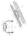
- Corresponding Fig. 1 comprises a partially shown light band 1 at least two lights 2, which follow one another directly in a direction indicated by a double arrow longitudinal direction 3 of the light band 1.
- This longitudinal direction 3 defines at the same time an axial direction or axial direction of the light band 1 and the lights 2 and their components. In this case, adjacent lights 2 abut each other at the front or axially.
- Corresponding impact limits are in Fig. 1 denoted by 4. It is clear that these impact limits 4 can be made dust-tight and / or moisture-proof when the light band 1 is finished with corresponding sealing means. In the region of these impact boundaries 4 extends in each case one, characterized by a brace joint region 5, in which the adjacent lights 2 are attached to each other.
- Each luminaire 2 comprises a mounting rail 6 on which at least one device carrier 7 can be fastened.
- the device carrier 7 has the same length as the mounting rail 6.
- the respective lamp 2 as a single luminaire outside a light band 1 can be used.
- individual device carriers 7 can also be fastened to a plurality of mounting rails 6 at the same time.
- the device carrier 7 on an upper side facing the carrier rail 6 has an electrical contact device 8 and at least one electronic module 9.
- At one side facing away from the mounting rail 6 underside two electrical connections 10 are provided on the equipment rack 7 here, via which a light bulb, not shown here, can be attached to the equipment carrier 7 and electrically connected.
- the support rail 6 is configured as a U-shaped profile body and accordingly has a base profile 11 and two web profiles 12 protruding therefrom.
- the base profile 11 and the web profiles 12 bound an interior 13 of the support rail 6 or the luminaire 2 on three sides.
- said inner space 13 is closed at the base profile 11 opposite fourth side.
- a current-carrying profile 14 can be arranged, which extends band-shaped substantially over the entire length of the support rail 6 and allows the power supply and the electrical control of electrical loads of the lamp 2.
- the two web profiles 12 each have a pocket 15 on an end region remote from the base profile 11.
- the two pockets 15 are each formed on an inner side 13 facing the inside of the respective web profile 12.
- the two pockets 15 are realized in that the web profiles 12 are bent in their end by about 180 ° inwards.
- a connector 16 For the connection of two in the longitudinal direction 3 of the light band 1 successive lights 2, a connector 16 is used. Said connector 16 indicates accordingly Fig. 6 two web portions 17 and a base portion 18. The base portion 18 connects the two web portions 17 with each other so that the connector 16 in the region of the base portion 18 is designed U-shaped. This U-shaped cross section is in Fig. 5 particularly recognizable.
- the connector 16 is designed in terms of its dimensions so that it can be inserted axially into the two support rails 6 that are to be connected to each other. In the inserted state, the in Fig. 5 is particularly clear, come the support rail 6 facing outer sides of the connector 16 to the connector 16 facing inner sides of the support rail 6 to the plant.
- the connector 16 is in terms of its outer contour shaped largely complementary to the inner contour of the mounting rails 6. It is noteworthy that the web portions 17 of the connector 16 engage with their end portions 19 remote from the base portion 18 into the pockets 15 of the web profiles 12. The pockets 15 may be suitably dimensioned so that they clamp the end portions 19 of the web portions 17 inserted therein. In this way, a secure positioning of the connector 16 in the mounting rails 6 can be realized. The clamping also increases the static friction and thus the adhesion between the connector 16 and the support rails. 6
- Fig. 5 can be removed, the base profile 11 of the respective support rail 6 forms a chamber 20 which is open to the interior 13 of the support rail 6.
- this chamber 20 is limited by two wall profiles 21 and by a bottom profile 22.
- the bottom profile 22 connects the two wall profiles 21 with each other, wherein the two wall profiles 21 extend parallel to the web profiles 12.
- the current-carrying profile 14 may be accommodated.
- two wall sections 23 are formed on the base section 18 of the connector 16, which project outwardly with respect to the interior 13. In the process, these wall sections 23 engage in the chamber 20.
- the wall sections 23 are positioned and dimensioned so that they come to rest with their outer sides facing away from each other on facing inner sides of the wall profiles 21. As a result, the position of the connector 16 in the support rails 6 is stabilized. It may be particularly expedient to design the wall sections 23 so that they are clamped between the wall profiles 21, as a result of which the non-positive retention of the connector 16 in the mounting rails 6 can be significantly improved.
- the wall profiles 21 each form an undercut 24. This is located in the chamber 20 and is thus remote from the interior 13.
- the wall sections 23 of the connector 16 are in the example now shaped so that they engage behind the respective undercut 24 of the associated wall profile 21. This results in addition to a form fit, which significantly improves the transmission of bending moments between the interconnected mounting rails 6.
- the wall portions 23 of the connector 16 have accordingly Fig. 6 Longitudinal ends 25 which have a longitudinal distance 27 from longitudinal ends 26 of the web portions 17.
- Said longitudinal distance 27 is expedient at least the same size as a length 28 of the wall sections 23. In the example shown, said longitudinal spacing 27 is approximately twice as large as the length 28 of the wall sections 23.
- the longitudinal ends 26 of the web portions 17 may also have a longitudinal distance 29 from longitudinal ends 30 of the base portion 18.
- a lateral support of the two web portions 17 is not over the entire length, but spaced from their longitudinal ends 26.
- the threading of the connector 16 is simplified in the end faces of the support rails 6.
- this longitudinal distance 29 is at least the same size as a length 31 of the base section 18.
- a wall thickness 33 of the connector 16 is about twice as large as a wall thickness 34 of the support rail 6. Since the support rails 6 and the connector 16 are preferably sheet metal bodies, the wall thicknesses mentioned correspond to sheet thicknesses of 33.34. Accordingly, the connector 16 has a sheet thickness 33, while the respective support rail 6 has a sheet thickness 34 which is only about half as large as the sheet thickness 33 of the connector 16th
- the base portion 18 of the connector 16 has a through hole 35. This is limited to the web portions 17 through the wall portions 23. Through the opening 35, the chamber 20 and the interior 13 are interconnected.
- the support rails 6 are each provided at their longitudinal ends or at the impact boundaries 4 in the base profile 11 with an outbreak region 36.
- the respective breakout region 36 is in this case via a predetermined breaking point 37 connected to the rest of the base profile 11.
- the breakout regions 36 can thus easily break out along the predetermined breaking points 37 and thus be removed particularly easily from the base profile 11.
- the broken out breakout areas 36 then release a connection opening, which is not described here in more detail, which is aligned with the passage opening 35 of the connector 16. In this way, a cable passage can be created particularly simple, which makes it possible to connect the running inside the light band 1 wiring with a building energy supply.
- the outbreak areas 36 have in the plan view of a remote from the device carrier 7 top of the support rail 6 in the example a U-profile. As a result, the two broken out break-off regions 36 together form an oval connection opening. In cross-section of Fig. 5 is one of the breakout areas 36 recognizable with its predetermined breaking point 37.
- the connector 16 is equipped for each support rail 6 with at least one protective conductor device 38.
- the connector 16 is equipped with exactly two protective conductor devices 38, which are each assigned to one of the mounting rails 6. These protective conductor devices 38 are designed so that they produce an electrical connection between the connector 16 and the respective support rail 6 when inserting the connector 16 into the respective support rail 6.
- the support rails 6 are each connected to the connector 16 and electrically conductive with each other.
- a through-connection for an electrical protective conductor can thus be ensured.
- the respective protective conductor device 38 may be equipped with at least one scraping edge 39.
- the respective protective conductor device 38 has in each case two such scraper edges 39.
- these scraper edges 39 can be an electrically insulating coating or an electrically insulating coating of the respective mounting rail 6 locally remove. The respective coating or coating is scraped off. Since the mounting rails 6 and the connector 16 are made of sheet metal, the desired electrical connection can thus be realized via the protective conductor device 38.
- the respective protective conductor device 38 is also designed as a pull-out protection for the connector 16 inserted into the respective support rail 6.
- the plugged into the respective mounting rail 6 connector 16 is secured in the extension direction by means of the protective conductor 38, whereby a withdrawal of the connector 16 from the respective support rail 6 considerably more difficult and is not possible with the usually occurring loads.
- the respective protective conductor device 38 is expediently designed so that its electrical contact with the respective support rail 6 by means of a tool, e.g. with the help of a screwdriver with a flat profile, without destroying the protective conductor device 38 is solvable. If the protective conductor device 38 is also designed as a pull-out protection device, this pull-out protection can also be released with the aid of the respective tool, without destroying the protective conductor device 38.
- the respective protective conductor device 38 can be integrally formed on the connector 16.
- the protective conductor device 38 is expediently designed as a clamp 40, which is also referred to below as a protective conductor clamp 40.
- the respective protective conductor clamp 40 is attached to the connector 16.
- the protective conductor clamp 40 is made of a spring steel and equipped with a clamping pocket 41, which in Fig. 3 recognizable is. With the help of this clamping pocket 41, the respective protective conductor clamp 40 is attached to the base portion 18.
- the protective conductor clamp 40 is attached through the passage opening 35 at the base portion 18.
- an actuating hook 42 is formed, on which the respective tool for releasing the protective conductor clamp 40 can attack.
- Corresponding Fig. 6 can be formed on the respective wall portion 23 each have a stop 43 which limits the insertion depth of the connector 16 in the respective support rail 6.
- the respective stop 43 is expediently arranged centrally with respect to the respective wall section 23.
- the respective web portion 17 has in its end region 19 on a side facing away from the base portion 18 a notch 44. These notches 44 are arranged in the same cross-sectional plane in which the stops 43 are located.
- the notches 44 can be used, for example, for positioning a seal.
- the connector 16 is constructed symmetrically according to the embodiments shown here. For example. it is mirror-symmetrical with respect to a centrally arranged cross-sectional plane. In addition, the connector 16 is constructed mirror-symmetrically with respect to a longitudinal plane running parallel to the web sections 17.
- the connector 16 has accordingly Fig. 3 a total length 45 that is at least three times greater than one in Fig. 5 drawn width 46 of the mounting rail 6.
- Eg. is the length 45 of the connector 16 in a range of values which is at least three times and at most six times greater than the width 46 of the support rail. 6
- the web portions 17 are provided with a plurality of openings 47, so that a truss structure is formed. This allows e.g. significantly reduce the weight of the connector 16.
Landscapes
- Engineering & Computer Science (AREA)
- Architecture (AREA)
- Civil Engineering (AREA)
- Structural Engineering (AREA)
- General Engineering & Computer Science (AREA)
- Arrangement Of Elements, Cooling, Sealing, Or The Like Of Lighting Devices (AREA)
- Fastening Of Light Sources Or Lamp Holders (AREA)
- Glass Compositions (AREA)
- Endoscopes (AREA)
- Vessels And Coating Films For Discharge Lamps (AREA)
Claims (13)
- Bande lumineuse présentant au moins deux luminaires (2),- chaque luminaire (2) présentant un rail porteur (6), sur lequel au moins un support d'appareil (7) peut être fixé,- le rail porteur (6) respectif étant conçu en forme de U et présentant un profilé de base (11) et deux profilés à nervure (12),- le profilé à nervure (12) respectif formant une poche (15) sur une zone d'extrémité éloignée du profilé de base (11) sur un côté intérieur tourné respectivement vers l'autre profilé à nervure (12),- au moins deux luminaires (2), qui se suivent dans le sens longitudinal (3) de la bande lumineuse (1), étant fixés l'un à l'autre au moyen d'un connecteur (16),- le connecteur (16) présentant deux parties de nervure (17) et une partie de base (18), qui relie les deux parties de nervure (17) l'une à l'autre, de telle sorte que le connecteur (16) est conçu en forme de U au moins dans la zone de la partie de base (18),- le connecteur (16) des deux rails porteurs (6) des deux luminaires (2) consécutifs étant enfiché côté avant,- des côtés extérieurs, tournés vers le rail porteur (6) respectif, du connecteur (16) s'appliquant sur des côtés intérieurs, tournés vers le connecteur (16), des rails porteurs (6),- les parties de nervure (17) du connecteur (16) s'engageant avec leurs zones d'extrémité (19) éloignées de la partie de base (18) dans les poches (15) des profilés à nervure (12),- le profilé de base (11) du rail porteur (6) respectif formant une chambre (20) ouverte vers l'intérieur (13) du rail porteur (6), laquelle chambre est délimitée par deux profilés de paroi (21) agencés parallèlement aux profilés à nervure (12) et par un profilé de sol (22) reliant entre eux les profilés de paroi (21),- des parties de paroi (23) dépassant vers l'extérieur étant formées sur la partie de base (18) du connecteur (16), lesquelles parties s'engagent dans la chambre (20) et s'appliquent avec leurs côtés extérieurs opposés les uns aux autres sur les côtés intérieurs tournés les uns vers les autres des profilés de paroi (21),
caractérisée- en ce que les profilés de paroi (21) forment à chaque fois une contre-dépouille (24),- en ce que les parties de paroi (23) sont formées de telle sorte qu'elles saisissent par l'arrière la contre-dépouille (24) respective du profilé de paroi (21) spécifique. - Bande lumineuse selon la revendication 1,
caractérisée en ce que
les extrémités longitudinales (25) des parties de paroi (23) présentent à chaque fois un espacement longitudinal (27) par rapport aux extrémités longitudinales (26) des parties de nervure (17). - Bande lumineuse selon la revendication 2,
caractérisée en ce que
l'espacement longitudinal (27) respectif est au moins aussi grand ou au moins deux fois plus grand qu'une longueur (28) des parties de paroi (23). - Bande lumineuse selon l'une quelconque des revendications 1 à 3,
caractérisée en ce que
le connecteur (16) et les rails porteurs (6) sont fabriqués en tôle, une épaisseur de tôle (33) sur le connecteur (16) étant plus grande, en particulier au moins deux fois plus grande, qu'une épaisseur de tôle (34) sur les rails porteurs (6). - Bande lumineuse selon l'une quelconque des revendications 1 à 4,
caractérisée en ce que
les extrémités longitudinales (30) de la partie de base (18) présentent à chaque fois un espacement longitudinal (29) par rapport aux extrémités longitudinales (26) des parties de nervure (17). - Bande lumineuse selon la revendication 5,
caractérisée en ce que
l'espacement longitudinal (29) respectif est au moins aussi grand qu'une longueur (31) de la partie de base (18). - Bande lumineuse selon l'une quelconque des revendications 1 à 6,
caractérisée en ce que
les parties de nervure (17) présentent des chanfreins d'entrée (32) sur leurs extrémités longitudinales (26) dans les zones d'extrémité (19) éloignées de la partie de base (18). - Bande lumineuse selon l'une quelconque des revendications 1 à 7,
caractérisée- en ce que la partie de base (18) présente une ouverture de passage (35),- en ce que les rails porteurs (6) présentent sur chacune de leurs extrémités longitudinales dans le profilé de base (11) à chaque fois une zone de creux (36), qui est reliée par un point de rupture théorique (37) au profilé de base (11) restant et qui, lorsqu'il est évidé, libère une ouverture de raccordement s'alignant avec l'ouverture de passage (35) du connecteur (16). - Bande lumineuse selon l'une quelconque des revendications 1 à 8,
caractérisée en ce que le connecteur (16) présente pour chaque rail porteur (6) au moins à chaque fois un dispositif conducteur de protection (38), qui, lors de l'enfichage du connecteur (16) dans le rail porteur (6) respectif, établit une liaison électrique entre le connecteur (16) et le rail porteur (6) respectif. - Bande lumineuse selon la revendication 9,
caractérisée
en ce que le dispositif conducteur de protection (38) respectif présente au moins une arête de grattage (39), qui, lors de l'enfichage du connecteur (16), enlève localement un revêtement électro-isolant ou un laquage électro-isolant du rail porteur (6) respectif. - Bande lumineuse selon la revendication 9 ou 10,
caractérisée en ce que
le dispositif conducteur de protection (3) respectif est conçu d'autre part comme blocage d'extraction pour le connecteur (16) enfiché dans le rail porteur (6) respectif. - Bande lumineuse selon l'une quelconque des revendications 9 à 11,
caractérisée en ce que
le dispositif conducteur de protection (38) respectif est conçu de telle sorte que sa mise en contact avec le rail porteur (6) respectif peut être détachée au moyen d'un outil sans détruire le dispositif conducteur de protection (38). - Bande lumineuse selon l'une quelconque des revendications 9 à 12,
caractérisée en ce que
le dispositif conducteur de protection (38) respectif est conçu comme agrafe conductrice de protection (40), qui est un composant séparé par rapport au connecteur (16) et est rapporté sur le connecteur (16).
Priority Applications (4)
| Application Number | Priority Date | Filing Date | Title |
|---|---|---|---|
| PL09159649T PL2249077T3 (pl) | 2009-05-07 | 2009-05-07 | Pas świetlny |
| AT09159649T ATE520931T1 (de) | 2009-05-07 | 2009-05-07 | Lichtband |
| EP09159649A EP2249077B1 (fr) | 2009-05-07 | 2009-05-07 | Bande lumineuse |
| DE202010006329U DE202010006329U1 (de) | 2009-05-07 | 2010-05-03 | Lichtband |
Applications Claiming Priority (1)
| Application Number | Priority Date | Filing Date | Title |
|---|---|---|---|
| EP09159649A EP2249077B1 (fr) | 2009-05-07 | 2009-05-07 | Bande lumineuse |
Publications (2)
| Publication Number | Publication Date |
|---|---|
| EP2249077A1 EP2249077A1 (fr) | 2010-11-10 |
| EP2249077B1 true EP2249077B1 (fr) | 2011-08-17 |
Family
ID=40756457
Family Applications (1)
| Application Number | Title | Priority Date | Filing Date |
|---|---|---|---|
| EP09159649A Active EP2249077B1 (fr) | 2009-05-07 | 2009-05-07 | Bande lumineuse |
Country Status (4)
| Country | Link |
|---|---|
| EP (1) | EP2249077B1 (fr) |
| AT (1) | ATE520931T1 (fr) |
| DE (1) | DE202010006329U1 (fr) |
| PL (1) | PL2249077T3 (fr) |
Cited By (2)
| Publication number | Priority date | Publication date | Assignee | Title |
|---|---|---|---|---|
| RU2680127C1 (ru) * | 2018-04-02 | 2019-02-15 | Марат Габдулгазизович Бикмуллин | Светодиодный светильник с функцией кабельного лотка |
| WO2025181084A1 (fr) * | 2024-03-01 | 2025-09-04 | Trilux Gmbh & Co. Kg | Bande lumineuse à composants positionnés de manière optimisée |
Families Citing this family (12)
| Publication number | Priority date | Publication date | Assignee | Title |
|---|---|---|---|---|
| DE202010013079U1 (de) * | 2010-12-07 | 2011-12-08 | Lite-Licht Gmbh | Verbindungselement für ein Lichtbandschienensystem bzw. ein Tragschienensystem für stabförmige Leuchtmittel |
| DE102011017702A1 (de) * | 2011-04-28 | 2012-10-31 | Zumtobel Lighting Gmbh | Lichtbandsystem und Konvertereinheit hierfür |
| DE102012202148A1 (de) * | 2012-02-13 | 2013-08-14 | Trilux Gmbh & Co. Kg | Lichtbandsystem |
| DE202014100948U1 (de) | 2014-03-03 | 2015-06-09 | Zumtobel Lighting Gmbh | Leuchte mit auswechselbaren Leuchtmodulen |
| DE102015112838A1 (de) * | 2015-08-05 | 2017-02-09 | Selux Ag | Beleuchtungsanordnung für Stromschienen |
| DE102018106233A1 (de) * | 2018-03-16 | 2019-09-19 | Trilux Gmbh & Co. Kg | System zur Realisierung eines Lichtbands |
| GB2590510B (en) * | 2019-12-20 | 2022-12-07 | Thorn Lighting Ltd | Longitudinal luminaire with alignment features |
| DE202019107217U1 (de) * | 2019-12-23 | 2021-03-24 | Zumtobel Lighting Gmbh | Geräteträger sowie Leuchte mit Geräteträger |
| DE102020129925A1 (de) | 2020-11-12 | 2022-05-12 | Trilux Gmbh & Co. Kg | Befestigung einer Kupplung für ein Lichtbandsystem |
| EP4361499A3 (fr) * | 2022-10-07 | 2024-06-26 | Trilux GmbH & Co. KG | Bande lumineuse dotée de composants optimisés pour le démontage |
| DE102023112178A1 (de) * | 2023-05-09 | 2024-11-14 | Trilux Gmbh & Co. Kg | Abgedichtetes Lichtband |
| DE102023119082A1 (de) * | 2023-07-19 | 2025-01-23 | Trilux Gmbh & Co. Kg | Lichtband mit Kratzfederkupplung |
Family Cites Families (12)
| Publication number | Priority date | Publication date | Assignee | Title |
|---|---|---|---|---|
| DE1693140U (de) * | 1953-11-30 | 1955-02-17 | Siemens Schukertwerke Ag | Anordnung zum verbinden von montageschienen fuer leuchten mit leuchtstofflampen. |
| DE1789301U (de) * | 1958-12-16 | 1959-05-27 | Hermann Jung | Langfeldleuchte. |
| GB930529A (en) * | 1961-03-14 | 1963-07-03 | Philips Electrical Ind Ltd | Improvements in or relating to devices for joining two channel strips end to end |
| NL298903A (fr) | 1962-10-11 | |||
| DE1489555B2 (de) * | 1963-10-07 | 1976-11-18 | Trilux-Lenze Kg, 5770 Arnsberg | Tragschiene zum anbringen von leuchten |
| DE3214595C2 (de) * | 1982-04-20 | 1984-06-28 | Fränkische Leuchten GmbH, 8729 Königsberg | Verbindungsstück für Leuchten mit schienenförmigen Teilen |
| DE4300550A1 (de) * | 1993-01-12 | 1994-07-14 | Trilux Lenze Gmbh & Co Kg | Lichtbandkupplung |
| DE4409488C2 (de) * | 1994-03-19 | 1996-09-12 | Lt Licht Technik Gmbh | Schienenverbinder |
| ATE335962T1 (de) * | 1997-04-07 | 2006-09-15 | Koninkl Philips Electronics Nv | Leuchteneinheit für lichtbandsystem |
| DE69836045T2 (de) * | 1997-04-09 | 2007-05-03 | Philips Intellectual Property & Standards Gmbh | Leuchteneinheit für Lichtbandsystem |
| DE19840058C2 (de) | 1998-09-03 | 2003-07-17 | Regiolux Gmbh | Verbindungselement zur Verbindung von zwei Tragschienen |
| DE19844029A1 (de) | 1998-09-25 | 2000-05-11 | Thorn Licht Gmbh | Verbindungselement für Schienenprofilelemente eines zeilenförmigen Lichtbands |
-
2009
- 2009-05-07 EP EP09159649A patent/EP2249077B1/fr active Active
- 2009-05-07 PL PL09159649T patent/PL2249077T3/pl unknown
- 2009-05-07 AT AT09159649T patent/ATE520931T1/de active
-
2010
- 2010-05-03 DE DE202010006329U patent/DE202010006329U1/de not_active Expired - Lifetime
Cited By (2)
| Publication number | Priority date | Publication date | Assignee | Title |
|---|---|---|---|---|
| RU2680127C1 (ru) * | 2018-04-02 | 2019-02-15 | Марат Габдулгазизович Бикмуллин | Светодиодный светильник с функцией кабельного лотка |
| WO2025181084A1 (fr) * | 2024-03-01 | 2025-09-04 | Trilux Gmbh & Co. Kg | Bande lumineuse à composants positionnés de manière optimisée |
Also Published As
| Publication number | Publication date |
|---|---|
| PL2249077T3 (pl) | 2012-01-31 |
| DE202010006329U1 (de) | 2010-08-05 |
| ATE520931T1 (de) | 2011-09-15 |
| EP2249077A1 (fr) | 2010-11-10 |
Similar Documents
| Publication | Publication Date | Title |
|---|---|---|
| EP2249077B1 (fr) | Bande lumineuse | |
| EP2091111B1 (fr) | Système de contact pour bandes lumineuses ou lampes | |
| DE202013104785U1 (de) | Reihenbausteinanordnung mit einem Energiebussystem | |
| EP2335967B1 (fr) | Pièce intercalaire pour système de barres conductrices | |
| EP4178047B1 (fr) | Connecteur pour une bande lumineuse | |
| EP0982978B1 (fr) | Boítier, en particulier boítier de serrure avec interconnections électriques | |
| EP2264363B1 (fr) | Lampe, capuchon terminal et bande lumineuse | |
| EP1475565B1 (fr) | Ensemble d'éclairage | |
| EP2827051B1 (fr) | Éclairage | |
| DE102011053859A1 (de) | Stromverteileranordnung und Abschlusskappe für Stromführungsprofile hierzu | |
| DE4323370C2 (de) | Profilleiste aus Isolierstoff zum Halten einer Vielzahl von elektrischen Leitungen | |
| DE2946622C2 (de) | Vorrichtung zum Befestigen von Gegenständen an einer Profilschiene mit in entgegengesetzten Richtungen auswärts abstehenden Flanschen | |
| DE102019114553A1 (de) | Dehnverbinder für eine Schleifleitung und Schleifleitung | |
| EP1853827B1 (fr) | Connecteur de profiles | |
| DE102014102260B4 (de) | Baukasten für die Abdichtung des Durchganges von Kabeln oder Adern, die durch eine Platte verlaufen sowie Verfahren zum Abdichten | |
| WO2013131605A1 (fr) | Composant de jonction de câbles servant à joindre l'extrémité d'un câble à la ou aux extrémités d'un ou plusieurs autres câbles | |
| EP2263292B1 (fr) | Dispositif de décharge de traction | |
| DE102007039171A1 (de) | Verfahren zur Montage bzw. zum Einbringen eines Hohlkörpers in eine Betonwand oder Betondecke | |
| DE102019126922A1 (de) | Tragschiene sowie Tragschienensystem mit Tragschiene | |
| AT17765U1 (de) | Stromschienenbauteil zum Bilden einer länglichen Stromschiene | |
| DE2538199A1 (de) | Anschlussklemme fuer elektrische leitungen | |
| DE102019126931A1 (de) | Stromschiene für Leuchten oder elektrische Einheiten | |
| DE102018124042A1 (de) | Energieführungskette mit Anschlusspunkt im Gelenk | |
| AT502571B1 (de) | Installationskasten | |
| DE102009008380A1 (de) | T-Verbindung |
Legal Events
| Date | Code | Title | Description |
|---|---|---|---|
| PUAI | Public reference made under article 153(3) epc to a published international application that has entered the european phase |
Free format text: ORIGINAL CODE: 0009012 |
|
| 17P | Request for examination filed |
Effective date: 20100223 |
|
| AK | Designated contracting states |
Kind code of ref document: A1 Designated state(s): AT BE BG CH CY CZ DE DK EE ES FI FR GB GR HR HU IE IS IT LI LT LU LV MC MK MT NL NO PL PT RO SE SI SK TR |
|
| GRAP | Despatch of communication of intention to grant a patent |
Free format text: ORIGINAL CODE: EPIDOSNIGR1 |
|
| GRAS | Grant fee paid |
Free format text: ORIGINAL CODE: EPIDOSNIGR3 |
|
| GRAA | (expected) grant |
Free format text: ORIGINAL CODE: 0009210 |
|
| AK | Designated contracting states |
Kind code of ref document: B1 Designated state(s): AT BE BG CH CY CZ DE DK EE ES FI FR GB GR HR HU IE IS IT LI LT LU LV MC MK MT NL NO PL PT RO SE SI SK TR |
|
| REG | Reference to a national code |
Ref country code: GB Ref legal event code: FG4D Free format text: NOT ENGLISH |
|
| REG | Reference to a national code |
Ref country code: CH Ref legal event code: EP |
|
| REG | Reference to a national code |
Ref country code: IE Ref legal event code: FG4D Free format text: LANGUAGE OF EP DOCUMENT: GERMAN |
|
| REG | Reference to a national code |
Ref country code: DE Ref legal event code: R096 Ref document number: 502009001119 Country of ref document: DE Effective date: 20111020 |
|
| REG | Reference to a national code |
Ref country code: NL Ref legal event code: VDEP Effective date: 20110817 |
|
| LTIE | Lt: invalidation of european patent or patent extension |
Effective date: 20110817 |
|
| PG25 | Lapsed in a contracting state [announced via postgrant information from national office to epo] |
Ref country code: SE Free format text: LAPSE BECAUSE OF FAILURE TO SUBMIT A TRANSLATION OF THE DESCRIPTION OR TO PAY THE FEE WITHIN THE PRESCRIBED TIME-LIMIT Effective date: 20110817 Ref country code: PT Free format text: LAPSE BECAUSE OF FAILURE TO SUBMIT A TRANSLATION OF THE DESCRIPTION OR TO PAY THE FEE WITHIN THE PRESCRIBED TIME-LIMIT Effective date: 20111219 Ref country code: LT Free format text: LAPSE BECAUSE OF FAILURE TO SUBMIT A TRANSLATION OF THE DESCRIPTION OR TO PAY THE FEE WITHIN THE PRESCRIBED TIME-LIMIT Effective date: 20110817 Ref country code: IS Free format text: LAPSE BECAUSE OF FAILURE TO SUBMIT A TRANSLATION OF THE DESCRIPTION OR TO PAY THE FEE WITHIN THE PRESCRIBED TIME-LIMIT Effective date: 20111217 Ref country code: NO Free format text: LAPSE BECAUSE OF FAILURE TO SUBMIT A TRANSLATION OF THE DESCRIPTION OR TO PAY THE FEE WITHIN THE PRESCRIBED TIME-LIMIT Effective date: 20111117 Ref country code: FI Free format text: LAPSE BECAUSE OF FAILURE TO SUBMIT A TRANSLATION OF THE DESCRIPTION OR TO PAY THE FEE WITHIN THE PRESCRIBED TIME-LIMIT Effective date: 20110817 Ref country code: NL Free format text: LAPSE BECAUSE OF FAILURE TO SUBMIT A TRANSLATION OF THE DESCRIPTION OR TO PAY THE FEE WITHIN THE PRESCRIBED TIME-LIMIT Effective date: 20110817 |
|
| REG | Reference to a national code |
Ref country code: PL Ref legal event code: T3 |
|
| PG25 | Lapsed in a contracting state [announced via postgrant information from national office to epo] |
Ref country code: GR Free format text: LAPSE BECAUSE OF FAILURE TO SUBMIT A TRANSLATION OF THE DESCRIPTION OR TO PAY THE FEE WITHIN THE PRESCRIBED TIME-LIMIT Effective date: 20111118 Ref country code: LV Free format text: LAPSE BECAUSE OF FAILURE TO SUBMIT A TRANSLATION OF THE DESCRIPTION OR TO PAY THE FEE WITHIN THE PRESCRIBED TIME-LIMIT Effective date: 20110817 Ref country code: CY Free format text: LAPSE BECAUSE OF FAILURE TO SUBMIT A TRANSLATION OF THE DESCRIPTION OR TO PAY THE FEE WITHIN THE PRESCRIBED TIME-LIMIT Effective date: 20110817 Ref country code: SI Free format text: LAPSE BECAUSE OF FAILURE TO SUBMIT A TRANSLATION OF THE DESCRIPTION OR TO PAY THE FEE WITHIN THE PRESCRIBED TIME-LIMIT Effective date: 20110817 |
|
| REG | Reference to a national code |
Ref country code: IE Ref legal event code: FD4D |
|
| PG25 | Lapsed in a contracting state [announced via postgrant information from national office to epo] |
Ref country code: SK Free format text: LAPSE BECAUSE OF FAILURE TO SUBMIT A TRANSLATION OF THE DESCRIPTION OR TO PAY THE FEE WITHIN THE PRESCRIBED TIME-LIMIT Effective date: 20110817 Ref country code: CZ Free format text: LAPSE BECAUSE OF FAILURE TO SUBMIT A TRANSLATION OF THE DESCRIPTION OR TO PAY THE FEE WITHIN THE PRESCRIBED TIME-LIMIT Effective date: 20110817 Ref country code: IE Free format text: LAPSE BECAUSE OF FAILURE TO SUBMIT A TRANSLATION OF THE DESCRIPTION OR TO PAY THE FEE WITHIN THE PRESCRIBED TIME-LIMIT Effective date: 20110817 |
|
| PG25 | Lapsed in a contracting state [announced via postgrant information from national office to epo] |
Ref country code: RO Free format text: LAPSE BECAUSE OF FAILURE TO SUBMIT A TRANSLATION OF THE DESCRIPTION OR TO PAY THE FEE WITHIN THE PRESCRIBED TIME-LIMIT Effective date: 20110817 Ref country code: EE Free format text: LAPSE BECAUSE OF FAILURE TO SUBMIT A TRANSLATION OF THE DESCRIPTION OR TO PAY THE FEE WITHIN THE PRESCRIBED TIME-LIMIT Effective date: 20110817 Ref country code: IT Free format text: LAPSE BECAUSE OF FAILURE TO SUBMIT A TRANSLATION OF THE DESCRIPTION OR TO PAY THE FEE WITHIN THE PRESCRIBED TIME-LIMIT Effective date: 20110817 |
|
| PLBE | No opposition filed within time limit |
Free format text: ORIGINAL CODE: 0009261 |
|
| STAA | Information on the status of an ep patent application or granted ep patent |
Free format text: STATUS: NO OPPOSITION FILED WITHIN TIME LIMIT |
|
| PG25 | Lapsed in a contracting state [announced via postgrant information from national office to epo] |
Ref country code: DK Free format text: LAPSE BECAUSE OF FAILURE TO SUBMIT A TRANSLATION OF THE DESCRIPTION OR TO PAY THE FEE WITHIN THE PRESCRIBED TIME-LIMIT Effective date: 20110817 |
|
| 26N | No opposition filed |
Effective date: 20120521 |
|
| REG | Reference to a national code |
Ref country code: DE Ref legal event code: R097 Ref document number: 502009001119 Country of ref document: DE Effective date: 20120521 |
|
| BERE | Be: lapsed |
Owner name: RIDI LEUCHTEN G.M.B.H. Effective date: 20120531 |
|
| PG25 | Lapsed in a contracting state [announced via postgrant information from national office to epo] |
Ref country code: HR Free format text: LAPSE BECAUSE OF FAILURE TO SUBMIT A TRANSLATION OF THE DESCRIPTION OR TO PAY THE FEE WITHIN THE PRESCRIBED TIME-LIMIT Effective date: 20120404 |
|
| PG25 | Lapsed in a contracting state [announced via postgrant information from national office to epo] |
Ref country code: MC Free format text: LAPSE BECAUSE OF NON-PAYMENT OF DUE FEES Effective date: 20120531 |
|
| PG25 | Lapsed in a contracting state [announced via postgrant information from national office to epo] |
Ref country code: MK Free format text: LAPSE BECAUSE OF FAILURE TO SUBMIT A TRANSLATION OF THE DESCRIPTION OR TO PAY THE FEE WITHIN THE PRESCRIBED TIME-LIMIT Effective date: 20110817 Ref country code: BE Free format text: LAPSE BECAUSE OF NON-PAYMENT OF DUE FEES Effective date: 20120531 |
|
| PG25 | Lapsed in a contracting state [announced via postgrant information from national office to epo] |
Ref country code: ES Free format text: LAPSE BECAUSE OF FAILURE TO SUBMIT A TRANSLATION OF THE DESCRIPTION OR TO PAY THE FEE WITHIN THE PRESCRIBED TIME-LIMIT Effective date: 20111128 |
|
| PG25 | Lapsed in a contracting state [announced via postgrant information from national office to epo] |
Ref country code: BG Free format text: LAPSE BECAUSE OF FAILURE TO SUBMIT A TRANSLATION OF THE DESCRIPTION OR TO PAY THE FEE WITHIN THE PRESCRIBED TIME-LIMIT Effective date: 20111117 |
|
| PG25 | Lapsed in a contracting state [announced via postgrant information from national office to epo] |
Ref country code: MT Free format text: LAPSE BECAUSE OF FAILURE TO SUBMIT A TRANSLATION OF THE DESCRIPTION OR TO PAY THE FEE WITHIN THE PRESCRIBED TIME-LIMIT Effective date: 20110817 |
|
| PG25 | Lapsed in a contracting state [announced via postgrant information from national office to epo] |
Ref country code: HR Free format text: LAPSE BECAUSE OF FAILURE TO SUBMIT A TRANSLATION OF THE DESCRIPTION OR TO PAY THE FEE WITHIN THE PRESCRIBED TIME-LIMIT Effective date: 20110817 |
|
| REG | Reference to a national code |
Ref country code: CH Ref legal event code: PL |
|
| PG25 | Lapsed in a contracting state [announced via postgrant information from national office to epo] |
Ref country code: LI Free format text: LAPSE BECAUSE OF NON-PAYMENT OF DUE FEES Effective date: 20130531 Ref country code: CH Free format text: LAPSE BECAUSE OF NON-PAYMENT OF DUE FEES Effective date: 20130531 |
|
| PG25 | Lapsed in a contracting state [announced via postgrant information from national office to epo] |
Ref country code: TR Free format text: LAPSE BECAUSE OF FAILURE TO SUBMIT A TRANSLATION OF THE DESCRIPTION OR TO PAY THE FEE WITHIN THE PRESCRIBED TIME-LIMIT Effective date: 20110817 |
|
| PG25 | Lapsed in a contracting state [announced via postgrant information from national office to epo] |
Ref country code: LU Free format text: LAPSE BECAUSE OF NON-PAYMENT OF DUE FEES Effective date: 20120507 |
|
| PG25 | Lapsed in a contracting state [announced via postgrant information from national office to epo] |
Ref country code: HU Free format text: LAPSE BECAUSE OF FAILURE TO SUBMIT A TRANSLATION OF THE DESCRIPTION OR TO PAY THE FEE WITHIN THE PRESCRIBED TIME-LIMIT Effective date: 20090507 |
|
| REG | Reference to a national code |
Ref country code: AT Ref legal event code: MM01 Ref document number: 520931 Country of ref document: AT Kind code of ref document: T Effective date: 20140507 |
|
| PG25 | Lapsed in a contracting state [announced via postgrant information from national office to epo] |
Ref country code: AT Free format text: LAPSE BECAUSE OF NON-PAYMENT OF DUE FEES Effective date: 20140507 |
|
| REG | Reference to a national code |
Ref country code: FR Ref legal event code: PLFP Year of fee payment: 8 |
|
| REG | Reference to a national code |
Ref country code: FR Ref legal event code: PLFP Year of fee payment: 9 |
|
| REG | Reference to a national code |
Ref country code: FR Ref legal event code: PLFP Year of fee payment: 10 |
|
| PGFP | Annual fee paid to national office [announced via postgrant information from national office to epo] |
Ref country code: FR Payment date: 20200527 Year of fee payment: 12 |
|
| PGFP | Annual fee paid to national office [announced via postgrant information from national office to epo] |
Ref country code: PL Payment date: 20200428 Year of fee payment: 12 Ref country code: GB Payment date: 20200528 Year of fee payment: 12 |
|
| GBPC | Gb: european patent ceased through non-payment of renewal fee |
Effective date: 20210507 |
|
| PG25 | Lapsed in a contracting state [announced via postgrant information from national office to epo] |
Ref country code: GB Free format text: LAPSE BECAUSE OF NON-PAYMENT OF DUE FEES Effective date: 20210507 |
|
| PG25 | Lapsed in a contracting state [announced via postgrant information from national office to epo] |
Ref country code: FR Free format text: LAPSE BECAUSE OF NON-PAYMENT OF DUE FEES Effective date: 20210531 |
|
| PG25 | Lapsed in a contracting state [announced via postgrant information from national office to epo] |
Ref country code: PL Free format text: LAPSE BECAUSE OF NON-PAYMENT OF DUE FEES Effective date: 20210507 |
|
| PGFP | Annual fee paid to national office [announced via postgrant information from national office to epo] |
Ref country code: DE Payment date: 20250528 Year of fee payment: 17 |