EP4178047B1 - Connecteur pour une bande lumineuse - Google Patents
Connecteur pour une bande lumineuse Download PDFInfo
- Publication number
- EP4178047B1 EP4178047B1 EP22206154.1A EP22206154A EP4178047B1 EP 4178047 B1 EP4178047 B1 EP 4178047B1 EP 22206154 A EP22206154 A EP 22206154A EP 4178047 B1 EP4178047 B1 EP 4178047B1
- Authority
- EP
- European Patent Office
- Prior art keywords
- plug
- connector
- plugs
- rail
- profile
- Prior art date
- Legal status (The legal status is an assumption and is not a legal conclusion. Google has not performed a legal analysis and makes no representation as to the accuracy of the status listed.)
- Active
Links
Images


Classifications
-
- H—ELECTRICITY
- H01—ELECTRIC ELEMENTS
- H01R—ELECTRICALLY-CONDUCTIVE CONNECTIONS; STRUCTURAL ASSOCIATIONS OF A PLURALITY OF MUTUALLY-INSULATED ELECTRICAL CONNECTING ELEMENTS; COUPLING DEVICES; CURRENT COLLECTORS
- H01R25/00—Coupling parts adapted for simultaneous co-operation with two or more identical counterparts, e.g. for distributing energy to two or more circuits
- H01R25/14—Rails or bus-bars constructed so that the counterparts can be connected thereto at any point along their length
- H01R25/145—Details, e.g. end pieces or joints
-
- F—MECHANICAL ENGINEERING; LIGHTING; HEATING; WEAPONS; BLASTING
- F21—LIGHTING
- F21V—FUNCTIONAL FEATURES OR DETAILS OF LIGHTING DEVICES OR SYSTEMS THEREOF; STRUCTURAL COMBINATIONS OF LIGHTING DEVICES WITH OTHER ARTICLES, NOT OTHERWISE PROVIDED FOR
- F21V21/00—Supporting, suspending, or attaching arrangements for lighting devices; Hand grips
- F21V21/005—Supporting, suspending, or attaching arrangements for lighting devices; Hand grips for several lighting devices in an end-to-end arrangement, i.e. light tracks
-
- F—MECHANICAL ENGINEERING; LIGHTING; HEATING; WEAPONS; BLASTING
- F21—LIGHTING
- F21V—FUNCTIONAL FEATURES OR DETAILS OF LIGHTING DEVICES OR SYSTEMS THEREOF; STRUCTURAL COMBINATIONS OF LIGHTING DEVICES WITH OTHER ARTICLES, NOT OTHERWISE PROVIDED FOR
- F21V23/00—Arrangement of electric circuit elements in or on lighting devices
- F21V23/06—Arrangement of electric circuit elements in or on lighting devices the elements being coupling devices, e.g. connectors
-
- H—ELECTRICITY
- H01—ELECTRIC ELEMENTS
- H01R—ELECTRICALLY-CONDUCTIVE CONNECTIONS; STRUCTURAL ASSOCIATIONS OF A PLURALITY OF MUTUALLY-INSULATED ELECTRICAL CONNECTING ELEMENTS; COUPLING DEVICES; CURRENT COLLECTORS
- H01R25/00—Coupling parts adapted for simultaneous co-operation with two or more identical counterparts, e.g. for distributing energy to two or more circuits
- H01R25/14—Rails or bus-bars constructed so that the counterparts can be connected thereto at any point along their length
- H01R25/142—Their counterparts
Definitions
- the present invention relates to a connector for electrically and mechanically connecting two luminaires in a light strip having two or more such luminaires, having the features of the preamble of claim 1.
- the invention also relates to a light strip equipped with at least one such connector.
- a generic connector is from the EP 2 479 851 B1 known and is intended for a light strip in which the respective light has a straight and elongated support profile which has a profile base and two opposing profile walls connected to one another by the profile base. Furthermore, the respective light is equipped with a straight and elongated current guide rail which is arranged on the profile base in a profile interior delimited by the profile base and the profile walls and which has several rail grooves running parallel to the longitudinal direction of the light and adjacent to the light in the transverse direction and several electrical conductors which can be contacted in the rail grooves.
- the connector suitable for electrically and mechanically connecting two such lights has a connecting body which has two opposing connecting walls which can be inserted at the front into the support profiles of two lights which are immediately adjacent in the longitudinal direction, so that the connecting walls extend along the profile walls.
- the known connector is also equipped with two axially and oppositely oriented plugs whose electrical contacts are electrically connected to one another in a common housing having the two plugs via corresponding cables.
- the two power supply rails are each axially equipped with axially pluggable sockets on the front, each of which has several electrical contact elements that engage in the rail grooves of the respective power guide rail and electrically contact the respective electrical conductors there.
- the two plugs of the known connector can now be plugged axially into the two sockets fixed to the power guide rails, whereby the two power guide rails are electrically contacted with each other via the connector.
- the document DE202018102741 U1 discloses an electrical connector that electrically connects the electrical wires of two light strips and provides a continuous light strip, wherein the connecting lines are mechanically protected by the connector housing and the assembly of the light strip is significantly simplified and can be carried out without tools.
- the present invention addresses the problem of providing an improved or at least a different embodiment for a connector of the type described above and for a light strip equipped therewith, which is characterized in particular by simplified handling and/or assembly or disassembly.
- the invention is based on the general idea of arranging the plugs on the connector body so that they can be adjusted so that the electrical connection between the adjacent lights can be created and separated independently of the mechanical connection between the adjacent lights.
- the plugs which form a first pair of plugs, are arranged so that they can be adjusted on the connector body in the height direction of the connector, i.e. perpendicular to the longitudinal direction of the connector, between an active position for creating an electrical connection and a passive position for releasing the electrical connection.
- its longitudinal direction corresponds to the longitudinal direction of the respective light.
- the height direction of the connector also corresponds to the height direction of the respective light.
- the connector presented here is suitable for the mechanical and electrical connection of two luminaires adjacent in the longitudinal clearance, wherein the respective luminaire has a straight and elongated support profile which has a profile base and two opposing profile walls connected to one another by the profile base, wherein the respective luminaire also has at least one straight and elongated current guide rail which is arranged on the profile base in a profile interior delimited by the profile base and the profile walls and which has a plurality of rail grooves running parallel to the longitudinal direction and adjacent in the transverse direction and a plurality of electrical conductors which can be contacted in the rail grooves.
- the connector with its connecting walls can be inserted into the support profiles of the neighboring lights in the longitudinal direction at the front in order to establish the mechanical connection of the two lights.
- the first plugs are positioned on the connector in the passive position in such a way that when the connector is axially inserted into the respective light, they do not collide with the current-carrying profile of the respective light.
- the first plugs can be adjusted from the passive position to the active position.
- the connector can have, in addition to the first pair of connectors, a second pair of connectors which has two second connectors, each of which has a plurality of contact elements with electrical contact zones.
- the contact zones of one second connector are electrically connected to the contact zones of the other second connector via second cables.
- the second connectors are arranged on the connector body so that they can be adjusted in height between a passive position and an active position. When the first and second connectors are adjusted to their passive position, the connector can be inserted into the support profiles of the two adjacent lights in the longitudinal direction at the front.
- the contact elements of the second connectors engage in other rail grooves of the same power guide rails or in rail grooves of other power guide rails of the two adjacent lights when the second connectors are adjusted in height from the passive position to the active position. This is done in such a way that in the active position, at least one contact zone of the second plug electrically contacts at least one line of the respective power supply rail of one lamp, while at least one contact zone of the other second plug electrically contacts at least one corresponding line of the respective power supply rail of the other lamp. The corresponding lines of the respective power supply rails of the neighboring lamps are then electrically contacted with one another via the wiring of the second plug.
- the power guide rails can provide only a single circuit, while in more complex cases they provide several, independent circuits, one of which can also be an emergency circuit.
- the possibility of equipping the connector with only the first pair of plugs on the one hand, or with the first pair of plugs and the second pair of plugs on the other hand, means that the connector can be easily adapted to the complexity of the respective light strip. This can save significant costs. It is noteworthy in this context that such light strips in large halls are often installed with a very large number of luminaires and a correspondingly large number of connectors, so that cost savings within the connectors can certainly lead to considerable savings.
- the respective second plug can be arranged in the transverse direction next to the respective first plug on the connecting body. This results in a compact design for the connector.
- the second connectors function in an essentially identical manner to the first connectors, but are used to contact other electrical conductors that are arranged either within the same current guide rails or in other, additional current guide rails.
- the respective lamp has two separate current guide rails running parallel to one another, namely a first current guide rail and a second current guide rail.
- the contact elements of the first plugs which are designed to complement the first current guide rails, in the active position only engage in the rail grooves of the first current guide rails
- the contact elements of the second plugs which are designed to complement the second current guide rails, in the active position only engage in the rail grooves of the second current guide rails.
- the first pair of plugs is therefore used exclusively for the electrical connection of the first current guide rails
- the second pair of plugs is used exclusively for the electrical connection of the second current guide rails. This can help to prevent confusion. In addition, this makes it easier to implement safe functionality.
- the first plugs differ geometrically from the second plugs, such that the respective first plug cannot be plugged into the second current guide rail complementary to the second plug, while at the same time the respective second plug cannot be plugged into the first current guide rail complementary to the first plug.
- This design prevents incorrect assembly of the connector and in particular increases the safety of the respective fitter.
- first plugs and the second plugs are arranged adjacent to one another on the connecting body and are designed in such a way that the respective first plug in its passive position blocks or at least hinders the adjacent second plug in its passive position, such that the respective second plug can only be adjusted to the active position if the adjacent first plug has previously been adjusted to the active position or is adjusted to the active position at the same time.
- the design presented here forces a predetermined sequence for the electrical contacting of the both current guide rails.
- the respective second current guide rail can only be electrically contacted if the adjacent first current guide rail is already electrically contacted. This measure can contribute significantly to the safety of the respective fitter.
- a further embodiment proposes that the second plugs are each designed as emergency power plugs that do not have a neutral conductor contact element. This results in a cost-effective design for the second plugs.
- the first plugs are each designed as standard plugs, each of which has a neutral conductor contact element that has a contact zone connected to a neutral conductor, wherein the first plugs designed as standard plugs can each be plugged into a first current guide rail designed as a standard current guide rail that has a neutral conductor.
- the respective support profile can be earthed via the neutral conductor, for example, in order to increase the operational reliability of the respective luminaire or light strip.
- the second plugs can also be designed as standard plugs, but the embodiment mentioned above is preferred, in which the second plugs are designed as emergency power plugs.
- a particularly advantageous embodiment is one which combines several of the above-mentioned embodiments, such that the second plugs designed as emergency power plugs can only be adjusted from the passive position to the active position when the adjacent first plug designed as a standard plug is adjusted to the active position. This ensures that the support profiles are already earthed when the respective emergency power circuit is electrically contacted via the connector. This makes it possible to dispense with an additional, separate neutral conductor in the emergency power circuit, since The neutral conductor of the circuit of the respective first current-carrying rail can be used for this purpose.
- the respective first plug designed as a standard plug can have a grounding contact that is electrically connected to the neutral conductor contact element and that electrically contacts the metallic connecting body at least in the active position of the respective first plug. This measure thus achieves forced grounding of the connecting body, which increases the operational reliability of the connector and thus of the light strip.
- the respective first plug and/or the respective second plug can have at least one latching hook.
- the connecting body can have at least one latching contour that is complementary to the respective latching hook.
- the respective latching hook can now latch with the respective latching contour at least in the active position of the respective first or second plug, whereby the active position of the respective first or second plug is secured. An independent adjustment of the respective plug from the active position to the passive position is thereby prevented.
- the respective locking contour is designed in such a way that it also works together with the locking hook of the respective first or second plug in the passive position to secure the passive position.
- the respective locking contour can have two locking openings for this purpose, which are arranged offset from one another in the vertical direction on the connecting body, so that the respective locking element, e.g. a locking lug, is in engagement with one locking opening in the passive position, while it is in engagement with the other locking opening in the active position. This ensures that the respective plug cannot automatically adjust itself from the passive position to the active position, for example during transport and assembly.
- This measure also increases the operational reliability and installation safety of the connector and thus of the light strip equipped with it.
- the connecting body can have a guide opening for the respective first or second plug, wherein the respective first or second plug has a guide element that engages in the respective guide opening.
- the respective guide element and the respective guide opening can now work together for the guided adjustment of the respective first or second plug in the height direction between the active position and the passive position. This achieves reliable adjustability of the plug in the height direction on the connecting body, which makes handling the connector easier during assembly and disassembly.
- the locking mechanism between the respective plug and the connecting body in the active position can be designed in such a way that it can only be released again with the help of a tool.
- the locking mechanism between the respective plug and the connecting body in the passive position can be designed in such a way that it can be released manually by the fitter, for example by overcoming a predetermined pressure force.
- the connector can be equipped with a seal that has a U-shaped sealing body that is arranged on the outside of the connecting body.
- This seal is designed in such a way that, when the connector is installed, it penetrates axially into the support profile of one light and the support profile of the other light in the longitudinal direction and seals against both support profiles on the inside, transverse to the longitudinal direction, i.e., almost radially. This ensures efficient sealing of the lights that follow one another in the light strip.
- a particularly advantageous development is one in which the sealing body has two sealing walls that are opposite one another in the transverse direction of the connector and a sealing base that connects the sealing walls to one another, the sealing body having a drainage channel on the outside that extends in the transverse direction along the sealing base and merges into the sealing walls.
- the drainage channel is thus located on an outside of the sealing body facing the support profiles and can drain off contaminants that can reach the seal on the front sides of the support profiles from the outside of the seal.
- particulate contaminants in conjunction with liquid contaminants that can arise, for example, through condensation can be flushed out.
- the seal can be clipped to the connecting body.
- corresponding clips with locking lugs can be integrally formed on the seal base and/or on the seal walls.
- the seal base can be adapted to the profile interiors of the support profiles in the area of the power guide rails.
- An embodiment in which the seal base has a separating web holder that extends in the longitudinal direction of the connector is particularly advantageous. This embodiment is particularly suitable for lights in which the support profile on the profile base has a separating web that protrudes into the profile interior and divides the receiving space formed there into two receiving chambers, namely a first receiving chamber for receiving the first power guide rail and a second receiving chamber for receiving the second power guide rail.
- the connecting body can also have a connecting base that connects the two connecting walls to each other.
- the connecting body can be connected to the connecting base and the two connecting walls are a one-piece sheet metal part made from a single piece of sheet metal by forming.
- the connecting walls can optionally have insertion bevels that make it easier to insert the connecting walls into the support profiles along the profile walls.
- Angled centering webs can optionally be formed on the connecting base and/or on the connecting walls, which protrude outwards from the respective connecting wall in the direction of the associated profile wall. With the help of these centering webs, tolerance-related shape deviations between the connecting body and the support profiles can be compensated. In addition, an elegant, almost flush transition of the axially consecutive support profiles is achieved.
- a light strip according to the invention has two or more elongated and linear lights that are adjacent to one another in their longitudinal direction. Furthermore, the light strip according to the invention has at least one connector of the type described above, which connects two adjacent lights of the light strip electrically and mechanically to one another.
- the lights of the light strip can each have a linear and elongated support profile that has a profile base and two opposing profile walls that are connected to one another by the profile base.
- the lights of the light strip can also have at least one linear and elongated current guide rail that is arranged on the profile base in a profile interior that is delimited by the profile base and the profile walls and that has a plurality of rail grooves that run parallel to the longitudinal direction of the light and are adjacent to the light in the transverse direction, and a plurality of electrical conductors that can be contacted in the rail grooves.
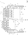
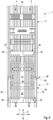
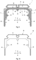
- FIG. 1 , 3 , 4 , 7 to 9 has a lamp 1 which is in the Figures 1 , 7 and 9 each shown in a cross-section running transversely to the longitudinal direction X, a support profile 2, at least one current guide rail 3, 4, at least one device carrier 5 and at least one plug 6.
- the longitudinal direction X is shown in the Figures 1 to 6 , 8 and 11 indicated by a double arrow and is in the Figures 1 , 7 , 9 and 10 perpendicular to the plane of the drawing.
- the luminaire 1 has an elongated and straight shape with respect to the longitudinal direction X.
- the luminaire 1 can be used in particular in a light strip 7, in which several such luminaires 1 are arranged one behind the other in the longitudinal direction X and are directly connected to one another.
- the luminaire 1 or the light strip 7 is intended for suspended ceiling installation.
- a ceiling 8 is shown to which the light strip 7 or the luminaires 1 are attached or suspended via several fastening elements 9.
- the support profile 2 of the respective light 1 is designed to be elongated and straight and has a profile base 10 and two profile walls 11 that are opposite one another in the transverse direction Y and are connected to one another by the profile base 10.
- the respective power guide rail 3, 4 is also designed to be straight and elongated and is arranged in a profile interior 12 on the profile base 10.
- the profile interior 12 is delimited by the profile base 10 and the profile walls 11.
- the respective power guide rail 3, 4 has several rail grooves 13 that run parallel to the longitudinal direction X and are adjacent in the transverse direction Y, as well as several electrical conductors 14 that can be electrically contacted in the rail grooves 13.
- the respective power guide rail 3, 4 has a rail base 15 from which several webs 16 protrude, which run parallel to one another and in the longitudinal direction X and form the rail grooves 13 between them in the transverse direction Y.
- the lines 14 are arranged on the longitudinal webs 16.
- the device carrier 5 also has an elongated and straight shape in the longitudinal direction X. It is clipped to the free ends of the profile walls 11 remote from the profile base 10 or is held by force and/or form locking.
- the device carrier 5 carries at least one electrical consumer (not shown here), which is preferably a lighting device, e.g. a plurality of light-emitting elements, preferably light-emitting diodes, with associated control unit and associated optics.
- the power supply of the respective consumer is via the respective power guide rail 3, 4 and such a plug 6, which for this purpose contacts the necessary lines 14 and is electrically connected to the respective consumer via cables (not shown).
- a connector 17 is used, which is inserted into the Figures 3 to 9
- the connector 17 has a connecting body 18 which has two opposite in the transverse direction Y connecting walls 19.
- the connecting body 18 also has a connecting base 20 that connects the two connecting walls 19 to one another.
- the connecting body 18 is expediently a one-piece sheet metal part.
- the connector 17 with its connecting walls 19 can be inserted into the support profiles 2 of two lamps 1 that are immediately adjacent in the longitudinal direction X.
- the connector 17 is in the Figures 3, 4 and 8 each inserted into the support profile 2 of only one of these lights 1.
- the connecting walls 19 When inserted, the connecting walls 19 extend along the profile walls 11.
- receiving pockets 21 can be formed on the profile walls 11 at their free ends facing away from the profile base 10, which can be inserted into the Figures 1 , 7 and 9 This results in a stable and secure support of the connector 17 on the two support profiles 2, which also stiffens them at the same time.
- the connector has a first plug pair 22, which has two first plugs 23, each of which has several contact elements 24.
- the contact elements 24 are designed like webs and have electrical contact zones 25, which can be arranged, for example, in Figure 7 are recognizable.
- the contact zones 25 of one first connector 23 are electrically connected via first cables 26 to the corresponding contact zones 25 of the other first connector 23.
- the first connectors 23 are arranged on the connecting body 18 so as to be adjustable in the height direction Z between an active position and a passive position.
- FIG 7 the active position of the respective first plug 23 is shown, in which the contact elements 24 of the first plug 23 engage in the rail grooves of the respective current guide rail 3, such that the contact zones 25 of the respective first plug 23 electrically contact the conductors 14 of the respective current guide rail 3.
- the respective first plug 23 In the passive position, the respective first plug 23 is in the height direction Z far enough from the respective current guide rail 3 spaced apart so that the contact elements 24 cannot penetrate into the rail grooves 13.
- the connector 17 can be inserted at the front into the support profiles 2 of the adjacent lights 1 in the longitudinal direction X.
- the respective first plug 23 is adjusted in the height direction Z relative to the connecting body 18 in such a way that the contact elements 24 engage in the rail grooves 13 of the respective current-carrying rail 3 in order to establish the desired contact between the contact zones 25 and the lines 14.
- the conductors 14 of the current guide rail 3 of one luminaire 1 are electrically connected to the corresponding conductors 14 of the current guide rail 3 of the other luminaire 1.
- the connector 17 also has a second plug pair 27, which has two second plugs 28.
- the second plugs 28 also each have several contact elements 24 with electrical contact zones 25.
- the contact zones 25 of the one second plug 28 are in accordance with Figure 8 electrically connected to the contact zones 25 of the other second plug 28 via second cables 29.
- the second plugs 28 are also arranged on the connecting body 18 so as to be adjustable in the height direction Z between a passive position and an active position.
- the passive position is shown as an example for the second plug 28 shown there.
- the connector 17 can be inserted into the support profiles 2 of the two adjacent lights 1 in the longitudinal direction X when the second plugs 28 are adjusted to their passive position. It is clear that for axial insertion of the connector 17 into the respective support profile 2, the respective first plug 23 and the respective second plug 28 are expediently in the passive position.
- the second plugs 28 can then be adjusted from the passive position to the active position in the height direction Z relative to the connecting body 18.
- the contact elements 24 of the second plugs 28 also penetrate into rail grooves 13 of the respective power guide rail 4 so that the contact zones 25 can electrically contact the respective conductors 14.
- the corresponding lines 14 of the respective power guide rails 4 of the two lights 1 are then electrically connected to one another.
- the respective light 1 has only a single current guide rail 3, 4.
- the contact elements 24 of the respective first plug 23 on the one hand and the contact elements 24 of the respective second plug 28 engage in different rail grooves 13 of the common current guide rail 3, 4.
- the advantageous embodiment shown here is preferred, in which the respective light 1 has two separate current guide rails running parallel to one another, namely a first current guide rail 3 and a second current guide rail 4.
- the contact elements 24 of the first plug 23 in their active position engage exclusively in the rail grooves 13 of the first current guide rail 3, while the contact elements 24 of the second plug 28 in the active position engage exclusively in the rail grooves 13 of the second current guide rail 4.
- the first plugs 23 and the second plugs 28 are geometrically configured differently, such that the respective first plug 23 cannot be plugged into the second current guide rail 4 complementary to the second plug, while the respective second plug 28 cannot be plugged into the first current guide rail 3 complementary to the first plug 23.
- the different geometries can ensure that if the connector 17 is inserted incorrectly, the contact elements 24 of the respective plug 23, 28 in the passive position are not aligned with the rail grooves 13 of the respective incorrect current guide rail 3, 4, so that they would collide with the longitudinal webs 16 when adjusted from the passive position towards the active position. This means that the respective plug 23, 28 cannot be plugged into the incorrect current guide rail 3, 4.
- first plugs 23 and the second plugs 28 are arranged adjacent to each other on the connecting body 18 and are also designed such that the respective first plug 23 in its passive position blocks the adjacent second plug 28 in its passive position, so that the second plug 28 cannot be adjusted to the active position before the first plug 23.
- step arrangement 30 is formed by a protruding step 31 formed on the respective second plug 28 and by a further step 32 formed by a recess on the respective first plug 23.
- both plugs 23, 28 can be moved into their active position at the same time.
- the electrical connection can be made more easily if the respective first plug 23 and then the respective second plug 28 are moved into the active position first.
- the respective second plug 28 can expediently be designed as an emergency power plug, which is characterized in that it does not have a neutral conductor contact element 24'.
- the respective first plug 23 can expediently be designed as a standard plug, each of which has a neutral conductor contact element 24', which has a neutral conductor contact zone 25' that can be electrically connected to a neutral conductor 14'.
- the first plug 23 designed as a standard plug can then be plugged into a first current guide rail 3 designed as a standard current guide rail, which has the neutral conductor 14'.
- the second plug 28 designed as an emergency power plug can only be adjusted from the passive position to the active position when the adjacent first plug 23 designed as a standard plug is adjusted to the active position.
- the neutral conductor 14' is already contacted, so that the connector 17 has contact protection for the respective fitter.
- the respective first plug 23 designed as a standard plug can have a grounding contact 33 electrically connected to the neutral conductor contact element 24'. At least in the active position, this grounding contact 33 creates an electrical contact with the connecting body 18, which is preferably a metal component.
- the respective first plug 23 and/or the respective second plug 28 has or have at least one locking element 34, which at least in the active position interacts with a complementary locking contour 35 in order to secure the respective plug 23, 28 in the active position.
- the respective locking contour 35 on the connecting body 18 is designed in such a way that it also interacts with the respective locking element in the passive position of the respective plug 23, 28. 34 to be secured passive position.
- the respective locking contour 35 can be designed in two parts or have two contour sections, e.g. in the form of locking openings, which are arranged offset from one another in the height direction Z on the connecting body 18.
- the associated locking element 34 e.g.
- the respective locking element 34 in the form of a locking lug, can then cooperate with one contour section in the passive position and with the other contour section in the active position.
- the respective locking element 34 can also be configured in two parts so that it has two different locking sections, with one locking section in the passive position cooperating with one contour section, while the other locking section in the active position cooperating with the other contour section.
- the locking elements 34 and the locking contours 35 are shown here as examples and only in a highly simplified and symbolic manner.
- the respective first connector 23 is locked in the active position, while the respective second connector 28 is locked in the passive position.
- a locking section 34' designed as a locking lug is supported in the passive position on the edge of a locking contour 35' designed as a locking opening.
- the connecting body 18 can have a guide opening 36 for the respective plug 23, 28.
- the respective plug 23, 28 has a guide element 37 that engages in the respective guide opening 36.
- the guide elements 37 and the guide openings 36 work together and enable a guided adjustment of the respective plug 23, 28 in the height direction Z in order to adjust the respective plug 23, 28 in a guided manner between the active position and the passive position.
- the connector 17 can also be equipped with a seal 38.
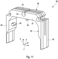
- the seal 38 has a U-shaped sealing body 39, which is arranged on the outside, i.e. on an outside facing the respective support profile 2, on the connecting body 18.
- the seal 38 When the connector 17 is installed, it penetrates in the longitudinal direction X on the one hand into the support profile 2 of one lamp 1 and on the other hand into the support profile 2 of the other lamp 1. Furthermore, when installed, the seal 38 lies sealingly on the inside of both support profiles 2, i.e. on an inner side of the respective support profile 2 facing the connecting body 18.
- the sealing body 39 has two sealing walls 40 opposite one another in the transverse direction Y and a sealing base 41 which connects the two sealing walls 40 to one another.
- the sealing body 39 can have a drainage channel 42 on the outside, i.e. on its outer side facing the respective support profile 2.
- the drainage channel 42 extends in the transverse direction Y along the sealing base 41 and merges into the two sealing walls 40.
- a rail receiving space formed on the profile base 10 is divided into two separate receiving chambers by means of a separating web 43 formed on the profile base 10, wherein one receiving chamber then receives the first current-carrying rail 3, while the other receiving chamber receives the second current-carrying rail 4.
- the seal 38 can now be Figures 3 to 5 , 10 and 11 be adapted to this design of the support profile 2 and also have a longitudinal groove 44 complementary to the separating web 43.
- barb-like clips 45 can be integrally formed on the seal 38 or on the seal body 39, which are clipped to the connecting body 18 and for this purpose penetrate corresponding clip openings 46, which according to Figure 9 on the connecting body 18.
- the seal 38 has three such clips 45, namely one on the seal base 41 and one each on the two seal walls 40.
- insertion bevels 47 which are formed on the connecting body 18 or on the connecting walls 19 and which facilitate the axial insertion of the connector 17 into the support profiles 2.
- centering webs 48 which are formed on the connecting body 18 or on the connecting walls 19 and/or on the connecting base 20 and which cause the support profiles 2 of the adjacent lights 1 to be centered or aligned on the connector 17.
- an optional locking mechanism 49 which has locking lugs 50 formed on the connecting walls 19, which, when a predetermined insertion position is reached, engage in complementary locking openings 51 which are formed on the profile walls 11, here in the area of the pockets 21.
Landscapes
- Engineering & Computer Science (AREA)
- General Engineering & Computer Science (AREA)
- Arrangement Of Elements, Cooling, Sealing, Or The Like Of Lighting Devices (AREA)
Claims (15)
- Connecteur (17) pour la liaison électrique et mécanique de deux lampes (1) dans une bande lumineuse (7) présentant deux ou plus lampes (1) de la sorte,- dans lequel la lampe (1) respective présente un profilé porteur (2) rectiligne et oblong qui présente un fond de profilé (10) et deux parois de profilé (11) opposées, reliées l'une à l'autre par le fond de profilé (10),- dans lequel la lampe (1) respective présente en outre au moins un rail conducteur de courant (3, 4) rectiligne et oblong qui est agencé dans un espace intérieur de profilé (12) délimité par le fond de profilé (10) et les parois de profilé (11) au niveau du fond de profilé (10) et qui présente plusieurs rainures de rail (13) s'étendant parallèlement au sens longitudinal (X) et contigües dans le sens transversal (Y) et plusieurs conducteurs (14) électriques pouvant être en contact dans les rainures de rail (13),- dans lequel le connecteur (17) présente un corps de liaison (18) avec deux parois de liaison (19) opposées qui sont enfichables côté avant dans les profilés porteurs (2) de deux lampes (1) directement contiguës dans le sens longitudinal (X), de telle manière que les parois de liaison (19) s'étendent le long des parois de profilé (11),- dans lequel le connecteur (17) présente une première paire de fiches (22) qui présente deux premières fiches (23) qui présentent respectivement plusieurs éléments de contact (24) avec des zones de contact (25) électriques,- dans lequel les zones de contact (25) de l'une première fiche (23) sont électriquement reliées aux zones de contact (25) de l'autre première fiche (23) par le biais de premiers câbles (26),caractérisé en ce que- les premières fiches (23) sont agencées de manière déplaçable au niveau du corps de liaison (18) dans le sens vertical (Z) entre une position active et une position passive,- le connecteur (17) est enfichable côté avant dans les profilés porteurs (2) des lampes (1) contiguës dans le sens longitudinal (X) lorsque des premières fiches (23) sont déplacées dans la position passive,- lorsque le connecteur (17) est enfiché dans les profilés porteurs (2) des deux lampes (1) contiguës, lorsque la première fiche (23) est déplacée de la position passive dans la position active dans le sens vertical (Z), les éléments de contact (24) des premières fiches (23) s'engagent dans les rainures de rail (13) des rails conducteurs de courant (3, 4) des deux lampes (1) contiguës, de sorte que dans la position active, au moins une des zones de contact (25) de l'une première fiche (23) est en contact électrique avec au moins une ligne (14) du rail conducteur de courant (3) de l'une lampe (1) tandis qu'au moins une des zones de contact (25) de l'autre première fiche (23) est en contact électrique avec au moins une ligne (14) du rail conducteur de courant (3, 4) de l'autre lampe (1).
- Connecteur (17) selon la revendication 1,
caractérisé en ce que- le connecteur (17) présente une seconde paire de fiches (27) qui présente deux secondes fiches (28) qui présentent respectivement plusieurs éléments de contact (24) avec des zones de contact (25) électriques,- les zones de contact (25) de l'une seconde fiche (28) sont électriquement reliées par le biais de seconds câbles (29) aux zones de contact (25) de l'autre seconde fiche (28),- les secondes fiches (28) sont agencées de manière déplaçable au niveau du corps de liaison (18) dans le sens vertical (Z) entre une position passive et une position active,- le connecteur (17) est enfichable côté frontal dans les profilés porteurs (2) des deux lampes (1) contiguës dans le sens longitudinal (X) lorsque des secondes fiches (28) sont déplacées dans leur position passive,- lorsque le connecteur (17) est enfiché dans les profilés porteurs (2) des deux lampes (1) contiguës, lorsque les secondes fiches (28) sont déplacées de la position passive dans la position active dans le sens vertical (Z), les éléments de contact (24) des secondes fiches (28) s'engagent dans d'autres rainures de rail (13) des mêmes rails conducteurs de courant (3, 4) ou dans des rainures de rail (13) d'autres rails conducteurs de courant (3, 4) des deux lampes (1) contiguës, de sorte que dans la position active, au moins une zone de contact (25) de l'une seconde fiche (28) est en contact électrique avec au moins une ligne (14) du rail conducteur de courant (3, 4) respectif, tandis qu'au moins une zone de contact (25) de l'autre seconde fiche (28) est en contact électrique avec au moins une ligne (14) du rail conducteur de courant (3, 4) respectif de l'autre lampe (1). - Connecteur (17) selon la revendication 2,
caractérisé en ce que- la seconde fiche (28) respective est agencée dans le sens transversal (Y) à côté de la première fiche (23) respective au niveau du corps de liaison (18). - Connecteur (17) selon la revendication 2 ou 3,
caractérisé en ce que- la lampe (1) respective présente deux rails conducteurs de courant séparés s'étendant parallèlement l'un à l'autre, à savoir un premier rail conducteur de courant (3) et un second rail conducteur de courant (4),- lorsque le connecteur (17) est enfiché dans les deux lampes (1) contiguës, les éléments de contact (24) des premières fiches (23) dans la position active s'engagent exclusivement dans les rainures de rail (13) du premier rail conducteur de courant (3), tandis que les éléments de contact (24) des secondes fiches (28) dans la position active s'engagent exclusivement dans les rainures de rail (13) du second rail conducteur de courant(4). - Connecteur (17) selon l'une quelconque des revendications 2 à 4,
caractérisé en ce que- les premières fiches (23) se distinguent géométriquement des secondes fiches (28) de sorte que la première fiche (23) respective ne soit pas enfichable avec le second rail conducteur de courant (4) complémentaire à la seconde fiche (28) et la seconde fiche (28) respective ne soit pas enfichable avec le premier rail conducteur de courant (3) complémentaire à la première fiche (23) respective. - Connecteur (17) selon l'une quelconque des revendications 2 à 5,
caractérisé en ce que- les premières fiches (23) et les secondes fiches (28) sont agencées de manière contiguë au niveau du corps de liaison (18) et configurées de sorte que la première fiche (23) respective dans sa position passive bloque la seconde fiche (28) contiguë dans sa position passive. - Connecteur (17) selon l'une quelconque des revendications 2 à 6,
caractérisé en ce que- les secondes fiches (28) sont configurées respectivement comme fiche d'alimentation de secours qui ne présentent aucun élément de contact neutre (24'). - Connecteur (17) selon l'une quelconque des revendications 1 à 7,
caractérisé en ce que- les premières fiches (23) sont configurées respectivement comme fiches standard qui présentent respectivement un élément de contact neutre (24') qui présente une zone de contact neutre (25') reliable à un conducteur neutre (14') et qui peuvent être enfichées respectivement avec un premier rail conducteur de courant (3) configuré comme rail conducteur de courant standard qui présente un conducteur neutre (14'). - Connecteur (17) selon les revendications 6, 7 et 8,
caractérisé en ce que- les secondes fiches (28) configurées comme fiches d'alimentation de secours ne sont pas déplaçables avant la première fiche (23) contiguë respective, configurée comme fiche standard, de la position passive à la position active. - Connecteur (17) selon la revendication 8 ou 9,
caractérisé en ce que- la première fiche (23) respective configurée comme fiche standard présente un contact de masse (33) relié électriquement à l'élément de contact neutre (24') qui est en contact électrique au moins dans la position active de la première fiche (23) respective avec le corps de liaison (18) métallique. - Connecteur (17) selon l'une quelconque des revendications 1 à 10,
caractérisé en ce que- la première et/ou seconde fiche (23, 28) respective présente au moins un élément d'encliquetage (34),- le corps de liaison (18) présente au moins un contour d'encliquetage (35) complémentaire à l'élément d'encliquetage (34) respectif,- l'élément d'encliquetage (34) respectif est oxydé au moins dans la position active de la première et/ou seconde fiche (23, 28) respective avec le contour d'encliquetage (35) respectif. - Connecteur (17) selon la revendication 11,
caractérisé en ce que- le contour d'encliquetage (35) respectif est configuré de sorte qu'il interagisse aussi dans la position passive de la première et/ou seconde fiche (23, 28) respective avec son élément d'encliquetage (34) pour assurer la position passive. - Connecteur (17) selon l'une quelconque des revendications 1 à 12,
caractérisé en ce que- le corps de liaison (18) présente une ouverture de guidage (36) pour la première et/ou seconde fiche (23, 28) respective,- la première et/ou seconde fiche (23, 28) respective présente un élément de guidage (37) qui s'engage dans l'ouverture de guidage (36) respective,- l'élément de guidage (37) respectif et l'ouverture de guidage (36) respective interagissent pour le déplacement guidé de la première et/ou seconde fiche (23, 28) respective dans le sens vertical (Z) entre la position active et la position passive. - Connecteur (17) selon l'une quelconque des revendications 1 à 13,
caractérisé en ce que- le connecteur (17) présente un joint d'étanchéité (38) qui présente un corps d'étanchéité (39) en forme de U qui est agencé à l'extérieur au niveau du corps de liaison (18),- le joint d'étanchéité (38) pénètre à l'état intégré du connecteur (17) dans le sens longitudinal (X) d'une part dans le profilé en creux (2) de l'une lampe (1) et d'autre part dans le profil porteur (2) de l'autre lampe (1) et repose de manière étanche à l'intérieur contre les deux profilés porteurs (2). - Bande lumineuse (7),- avec au moins deux lampes (1) oblongues et rectilignes qui sont contiguës dans leur sens longitudinal (X),- avec au moins un connecteur (17) selon l'une quelconque des revendications précédentes qui relie entre elles électriquement et mécaniquement deux lampes (1) contiguës de la bande lumineuse (7).
Applications Claiming Priority (1)
| Application Number | Priority Date | Filing Date | Title |
|---|---|---|---|
| DE102021212615.4A DE102021212615A1 (de) | 2021-11-09 | 2021-11-09 | Verbinder für ein Lichtband |
Publications (2)
| Publication Number | Publication Date |
|---|---|
| EP4178047A1 EP4178047A1 (fr) | 2023-05-10 |
| EP4178047B1 true EP4178047B1 (fr) | 2024-08-21 |
Family
ID=84330451
Family Applications (1)
| Application Number | Title | Priority Date | Filing Date |
|---|---|---|---|
| EP22206154.1A Active EP4178047B1 (fr) | 2021-11-09 | 2022-11-08 | Connecteur pour une bande lumineuse |
Country Status (3)
| Country | Link |
|---|---|
| EP (1) | EP4178047B1 (fr) |
| DE (1) | DE102021212615A1 (fr) |
| PL (1) | PL4178047T3 (fr) |
Cited By (1)
| Publication number | Priority date | Publication date | Assignee | Title |
|---|---|---|---|---|
| WO2024231484A3 (fr) * | 2023-05-09 | 2025-02-20 | Trilux Gmbh & Co. Kg | Bande lumineuse étanchéifiée |
Families Citing this family (3)
| Publication number | Priority date | Publication date | Assignee | Title |
|---|---|---|---|---|
| DE102023135686A1 (de) * | 2023-12-19 | 2025-06-26 | Zumtobel Lighting Gmbh | Verbinder für längliche Tragprofile eines Leuchtentragschienensystems |
| DE102024138897B3 (de) | 2024-12-19 | 2026-03-26 | Ridi Leuchten Gmbh | Beleuchtungsanordnung zum Abhängen von einer Decke eines Gebäudes |
| DE102024138895B3 (de) | 2024-12-19 | 2026-03-12 | Ridi Leuchten Gmbh | Beleuchtungsanordnung zum Abhängen von einer Decke eines Gebäudes |
Family Cites Families (6)
| Publication number | Priority date | Publication date | Assignee | Title |
|---|---|---|---|---|
| DE202010013167U1 (de) | 2010-12-20 | 2012-01-02 | Lite-Licht Gmbh | Leuchte, Lichtleiste oder dergleichen |
| DE102011002849A1 (de) | 2011-01-19 | 2012-07-19 | Ridi - Leuchten Gmbh | Elektrischer Verbinder |
| KR101351358B1 (ko) * | 2013-03-05 | 2014-01-23 | 주식회사 린노 | 라인 타입 조명장치 |
| US20170184290A1 (en) * | 2015-12-29 | 2017-06-29 | Davinci Opto Corp. | Track system |
| DE102017120828A1 (de) | 2017-09-08 | 2019-03-14 | Airbus Operations Gmbh | Stromschienenanordnung für ein Flugzeug |
| DE202018102741U1 (de) | 2018-05-16 | 2018-05-28 | Ridi Leuchten Gmbh | Lichtband |
-
2021
- 2021-11-09 DE DE102021212615.4A patent/DE102021212615A1/de active Pending
-
2022
- 2022-11-08 EP EP22206154.1A patent/EP4178047B1/fr active Active
- 2022-11-08 PL PL22206154.1T patent/PL4178047T3/pl unknown
Cited By (1)
| Publication number | Priority date | Publication date | Assignee | Title |
|---|---|---|---|---|
| WO2024231484A3 (fr) * | 2023-05-09 | 2025-02-20 | Trilux Gmbh & Co. Kg | Bande lumineuse étanchéifiée |
Also Published As
| Publication number | Publication date |
|---|---|
| PL4178047T3 (pl) | 2024-11-25 |
| DE102021212615A1 (de) | 2023-05-11 |
| EP4178047A1 (fr) | 2023-05-10 |
Similar Documents
| Publication | Publication Date | Title |
|---|---|---|
| EP4178047B1 (fr) | Connecteur pour une bande lumineuse | |
| EP1142070B1 (fr) | Dispositif de connexion electrique pour mettre en contact des brins de conducteurs | |
| EP2249077B1 (fr) | Bande lumineuse | |
| EP2091111B1 (fr) | Système de contact pour bandes lumineuses ou lampes | |
| EP3292602B1 (fr) | Passage de câble/ligne | |
| EP2479851B1 (fr) | Bande lumineuse avec connecteur électrique | |
| EP3217088B1 (fr) | Dispositif d'éclairage module sous la forme d'une bande lumineuse et système de liaison associé | |
| EP4413296B1 (fr) | Bande lumineuse modulaire dotée d'un dispositif de pré-centrage | |
| EP4413292B1 (fr) | Lampe dotée d'un cache de protection | |
| EP2400209A2 (fr) | Bande lumineuse | |
| EP3856568B1 (fr) | Raccord de dilatation pour une ligne de contact et ligne de contact | |
| AT526099B1 (de) | Schienenprofil für eine Profilleuchte oder für ein Schienenleuchtensystem | |
| EP2037550B1 (fr) | Protection contre le contact pour un rail | |
| WO2020065009A1 (fr) | Prise de torche et bande lumineuse | |
| DE102022112197A1 (de) | Modulares Lichtband mit Vorzentrierungseinrichtung | |
| EP2463959A1 (fr) | Connecteur | |
| EP4257870A1 (fr) | Élément de bande lumineuse et kit de rééquipement de flux de secours | |
| DE102021212616B4 (de) | Leuchte mit Tragprofil, Stromführungsschiene und Stecker | |
| EP4270681A1 (fr) | Connecteur de barre conductrice | |
| DE29709127U1 (de) | Elektrische Steckvorrichtung | |
| DE202021004004U1 (de) | Leuchte mit Tragprofil, Stromführungsschiene und Stecker | |
| DE10216250A1 (de) | Endstück für eine Stromschiene eines Stromschienensystems | |
| DE29823255U1 (de) | Lichtband-System | |
| DE102024106072A1 (de) | Montageoptimiertes System zur Realisierung eines Lichtbands | |
| EP2091112A1 (fr) | Système d'acheminement de courant pour bandes lumineuses ou lampes |
Legal Events
| Date | Code | Title | Description |
|---|---|---|---|
| PUAI | Public reference made under article 153(3) epc to a published international application that has entered the european phase |
Free format text: ORIGINAL CODE: 0009012 |
|
| STAA | Information on the status of an ep patent application or granted ep patent |
Free format text: STATUS: THE APPLICATION HAS BEEN PUBLISHED |
|
| AK | Designated contracting states |
Kind code of ref document: A1 Designated state(s): AL AT BE BG CH CY CZ DE DK EE ES FI FR GB GR HR HU IE IS IT LI LT LU LV MC ME MK MT NL NO PL PT RO RS SE SI SK SM TR |
|
| STAA | Information on the status of an ep patent application or granted ep patent |
Free format text: STATUS: REQUEST FOR EXAMINATION WAS MADE |
|
| 17P | Request for examination filed |
Effective date: 20231031 |
|
| RBV | Designated contracting states (corrected) |
Designated state(s): AL AT BE BG CH CY CZ DE DK EE ES FI FR GB GR HR HU IE IS IT LI LT LU LV MC ME MK MT NL NO PL PT RO RS SE SI SK SM TR |
|
| RIC1 | Information provided on ipc code assigned before grant |
Ipc: F21V 21/005 20060101ALI20240228BHEP Ipc: F21V 23/06 20060101ALI20240228BHEP Ipc: H01R 25/14 20060101AFI20240228BHEP |
|
| GRAP | Despatch of communication of intention to grant a patent |
Free format text: ORIGINAL CODE: EPIDOSNIGR1 |
|
| STAA | Information on the status of an ep patent application or granted ep patent |
Free format text: STATUS: GRANT OF PATENT IS INTENDED |
|
| INTG | Intention to grant announced |
Effective date: 20240408 |
|
| GRAS | Grant fee paid |
Free format text: ORIGINAL CODE: EPIDOSNIGR3 |
|
| GRAA | (expected) grant |
Free format text: ORIGINAL CODE: 0009210 |
|
| STAA | Information on the status of an ep patent application or granted ep patent |
Free format text: STATUS: THE PATENT HAS BEEN GRANTED |
|
| AK | Designated contracting states |
Kind code of ref document: B1 Designated state(s): AL AT BE BG CH CY CZ DE DK EE ES FI FR GB GR HR HU IE IS IT LI LT LU LV MC ME MK MT NL NO PL PT RO RS SE SI SK SM TR |
|
| REG | Reference to a national code |
Ref country code: GB Ref legal event code: FG4D Free format text: NOT ENGLISH |
|
| REG | Reference to a national code |
Ref country code: CH Ref legal event code: EP |
|
| REG | Reference to a national code |
Ref country code: DE Ref legal event code: R096 Ref document number: 502022001505 Country of ref document: DE |
|
| REG | Reference to a national code |
Ref country code: IE Ref legal event code: FG4D Free format text: LANGUAGE OF EP DOCUMENT: GERMAN |
|
| REG | Reference to a national code |
Ref country code: LT Ref legal event code: MG9D |
|
| REG | Reference to a national code |
Ref country code: NL Ref legal event code: MP Effective date: 20240821 |
|
| PG25 | Lapsed in a contracting state [announced via postgrant information from national office to epo] |
Ref country code: NO Free format text: LAPSE BECAUSE OF FAILURE TO SUBMIT A TRANSLATION OF THE DESCRIPTION OR TO PAY THE FEE WITHIN THE PRESCRIBED TIME-LIMIT Effective date: 20241121 |
|
| PG25 | Lapsed in a contracting state [announced via postgrant information from national office to epo] |
Ref country code: NL Free format text: LAPSE BECAUSE OF FAILURE TO SUBMIT A TRANSLATION OF THE DESCRIPTION OR TO PAY THE FEE WITHIN THE PRESCRIBED TIME-LIMIT Effective date: 20240821 Ref country code: FI Free format text: LAPSE BECAUSE OF FAILURE TO SUBMIT A TRANSLATION OF THE DESCRIPTION OR TO PAY THE FEE WITHIN THE PRESCRIBED TIME-LIMIT Effective date: 20240821 Ref country code: GR Free format text: LAPSE BECAUSE OF FAILURE TO SUBMIT A TRANSLATION OF THE DESCRIPTION OR TO PAY THE FEE WITHIN THE PRESCRIBED TIME-LIMIT Effective date: 20241122 Ref country code: PT Free format text: LAPSE BECAUSE OF FAILURE TO SUBMIT A TRANSLATION OF THE DESCRIPTION OR TO PAY THE FEE WITHIN THE PRESCRIBED TIME-LIMIT Effective date: 20241223 |
|
| PG25 | Lapsed in a contracting state [announced via postgrant information from national office to epo] |
Ref country code: BG Free format text: LAPSE BECAUSE OF FAILURE TO SUBMIT A TRANSLATION OF THE DESCRIPTION OR TO PAY THE FEE WITHIN THE PRESCRIBED TIME-LIMIT Effective date: 20240821 |
|
| PG25 | Lapsed in a contracting state [announced via postgrant information from national office to epo] |
Ref country code: LV Free format text: LAPSE BECAUSE OF FAILURE TO SUBMIT A TRANSLATION OF THE DESCRIPTION OR TO PAY THE FEE WITHIN THE PRESCRIBED TIME-LIMIT Effective date: 20240821 |
|
| PG25 | Lapsed in a contracting state [announced via postgrant information from national office to epo] |
Ref country code: IS Free format text: LAPSE BECAUSE OF FAILURE TO SUBMIT A TRANSLATION OF THE DESCRIPTION OR TO PAY THE FEE WITHIN THE PRESCRIBED TIME-LIMIT Effective date: 20241221 |
|
| PG25 | Lapsed in a contracting state [announced via postgrant information from national office to epo] |
Ref country code: HR Free format text: LAPSE BECAUSE OF FAILURE TO SUBMIT A TRANSLATION OF THE DESCRIPTION OR TO PAY THE FEE WITHIN THE PRESCRIBED TIME-LIMIT Effective date: 20240821 |
|
| PG25 | Lapsed in a contracting state [announced via postgrant information from national office to epo] |
Ref country code: RS Free format text: LAPSE BECAUSE OF FAILURE TO SUBMIT A TRANSLATION OF THE DESCRIPTION OR TO PAY THE FEE WITHIN THE PRESCRIBED TIME-LIMIT Effective date: 20241121 Ref country code: ES Free format text: LAPSE BECAUSE OF FAILURE TO SUBMIT A TRANSLATION OF THE DESCRIPTION OR TO PAY THE FEE WITHIN THE PRESCRIBED TIME-LIMIT Effective date: 20240821 |
|
| PG25 | Lapsed in a contracting state [announced via postgrant information from national office to epo] |
Ref country code: RS Free format text: LAPSE BECAUSE OF FAILURE TO SUBMIT A TRANSLATION OF THE DESCRIPTION OR TO PAY THE FEE WITHIN THE PRESCRIBED TIME-LIMIT Effective date: 20241121 Ref country code: PT Free format text: LAPSE BECAUSE OF FAILURE TO SUBMIT A TRANSLATION OF THE DESCRIPTION OR TO PAY THE FEE WITHIN THE PRESCRIBED TIME-LIMIT Effective date: 20241223 Ref country code: NO Free format text: LAPSE BECAUSE OF FAILURE TO SUBMIT A TRANSLATION OF THE DESCRIPTION OR TO PAY THE FEE WITHIN THE PRESCRIBED TIME-LIMIT Effective date: 20241121 Ref country code: NL Free format text: LAPSE BECAUSE OF FAILURE TO SUBMIT A TRANSLATION OF THE DESCRIPTION OR TO PAY THE FEE WITHIN THE PRESCRIBED TIME-LIMIT Effective date: 20240821 Ref country code: LV Free format text: LAPSE BECAUSE OF FAILURE TO SUBMIT A TRANSLATION OF THE DESCRIPTION OR TO PAY THE FEE WITHIN THE PRESCRIBED TIME-LIMIT Effective date: 20240821 Ref country code: IS Free format text: LAPSE BECAUSE OF FAILURE TO SUBMIT A TRANSLATION OF THE DESCRIPTION OR TO PAY THE FEE WITHIN THE PRESCRIBED TIME-LIMIT Effective date: 20241221 Ref country code: HR Free format text: LAPSE BECAUSE OF FAILURE TO SUBMIT A TRANSLATION OF THE DESCRIPTION OR TO PAY THE FEE WITHIN THE PRESCRIBED TIME-LIMIT Effective date: 20240821 Ref country code: GR Free format text: LAPSE BECAUSE OF FAILURE TO SUBMIT A TRANSLATION OF THE DESCRIPTION OR TO PAY THE FEE WITHIN THE PRESCRIBED TIME-LIMIT Effective date: 20241122 Ref country code: FI Free format text: LAPSE BECAUSE OF FAILURE TO SUBMIT A TRANSLATION OF THE DESCRIPTION OR TO PAY THE FEE WITHIN THE PRESCRIBED TIME-LIMIT Effective date: 20240821 Ref country code: ES Free format text: LAPSE BECAUSE OF FAILURE TO SUBMIT A TRANSLATION OF THE DESCRIPTION OR TO PAY THE FEE WITHIN THE PRESCRIBED TIME-LIMIT Effective date: 20240821 Ref country code: BG Free format text: LAPSE BECAUSE OF FAILURE TO SUBMIT A TRANSLATION OF THE DESCRIPTION OR TO PAY THE FEE WITHIN THE PRESCRIBED TIME-LIMIT Effective date: 20240821 |
|
| PG25 | Lapsed in a contracting state [announced via postgrant information from national office to epo] |
Ref country code: DK Free format text: LAPSE BECAUSE OF FAILURE TO SUBMIT A TRANSLATION OF THE DESCRIPTION OR TO PAY THE FEE WITHIN THE PRESCRIBED TIME-LIMIT Effective date: 20240821 Ref country code: RO Free format text: LAPSE BECAUSE OF FAILURE TO SUBMIT A TRANSLATION OF THE DESCRIPTION OR TO PAY THE FEE WITHIN THE PRESCRIBED TIME-LIMIT Effective date: 20240821 Ref country code: SM Free format text: LAPSE BECAUSE OF FAILURE TO SUBMIT A TRANSLATION OF THE DESCRIPTION OR TO PAY THE FEE WITHIN THE PRESCRIBED TIME-LIMIT Effective date: 20240821 |
|
| PG25 | Lapsed in a contracting state [announced via postgrant information from national office to epo] |
Ref country code: EE Free format text: LAPSE BECAUSE OF FAILURE TO SUBMIT A TRANSLATION OF THE DESCRIPTION OR TO PAY THE FEE WITHIN THE PRESCRIBED TIME-LIMIT Effective date: 20240821 |
|
| PG25 | Lapsed in a contracting state [announced via postgrant information from national office to epo] |
Ref country code: CZ Free format text: LAPSE BECAUSE OF FAILURE TO SUBMIT A TRANSLATION OF THE DESCRIPTION OR TO PAY THE FEE WITHIN THE PRESCRIBED TIME-LIMIT Effective date: 20240821 |
|
| PG25 | Lapsed in a contracting state [announced via postgrant information from national office to epo] |
Ref country code: SK Free format text: LAPSE BECAUSE OF FAILURE TO SUBMIT A TRANSLATION OF THE DESCRIPTION OR TO PAY THE FEE WITHIN THE PRESCRIBED TIME-LIMIT Effective date: 20240821 Ref country code: IT Free format text: LAPSE BECAUSE OF FAILURE TO SUBMIT A TRANSLATION OF THE DESCRIPTION OR TO PAY THE FEE WITHIN THE PRESCRIBED TIME-LIMIT Effective date: 20240821 |
|
| REG | Reference to a national code |
Ref country code: DE Ref legal event code: R097 Ref document number: 502022001505 Country of ref document: DE |
|
| PLBE | No opposition filed within time limit |
Free format text: ORIGINAL CODE: 0009261 |
|
| STAA | Information on the status of an ep patent application or granted ep patent |
Free format text: STATUS: NO OPPOSITION FILED WITHIN TIME LIMIT |
|
| PG25 | Lapsed in a contracting state [announced via postgrant information from national office to epo] |
Ref country code: MC Free format text: LAPSE BECAUSE OF FAILURE TO SUBMIT A TRANSLATION OF THE DESCRIPTION OR TO PAY THE FEE WITHIN THE PRESCRIBED TIME-LIMIT Effective date: 20240821 |
|
| PG25 | Lapsed in a contracting state [announced via postgrant information from national office to epo] |
Ref country code: LU Free format text: LAPSE BECAUSE OF NON-PAYMENT OF DUE FEES Effective date: 20241108 |
|
| 26N | No opposition filed |
Effective date: 20250522 |
|
| REG | Reference to a national code |
Ref country code: BE Ref legal event code: MM Effective date: 20241130 |
|
| PG25 | Lapsed in a contracting state [announced via postgrant information from national office to epo] |
Ref country code: SE Free format text: LAPSE BECAUSE OF FAILURE TO SUBMIT A TRANSLATION OF THE DESCRIPTION OR TO PAY THE FEE WITHIN THE PRESCRIBED TIME-LIMIT Effective date: 20240821 |
|
| PG25 | Lapsed in a contracting state [announced via postgrant information from national office to epo] |
Ref country code: BE Free format text: LAPSE BECAUSE OF NON-PAYMENT OF DUE FEES Effective date: 20241130 |
|
| PG25 | Lapsed in a contracting state [announced via postgrant information from national office to epo] |
Ref country code: IE Free format text: LAPSE BECAUSE OF NON-PAYMENT OF DUE FEES Effective date: 20241108 |
|
| PGFP | Annual fee paid to national office [announced via postgrant information from national office to epo] |
Ref country code: DE Payment date: 20251126 Year of fee payment: 4 |
|
| PGFP | Annual fee paid to national office [announced via postgrant information from national office to epo] |
Ref country code: AT Payment date: 20260113 Year of fee payment: 4 |
|
| PGFP | Annual fee paid to national office [announced via postgrant information from national office to epo] |
Ref country code: FR Payment date: 20251124 Year of fee payment: 4 |
|
| PGFP | Annual fee paid to national office [announced via postgrant information from national office to epo] |
Ref country code: PL Payment date: 20251020 Year of fee payment: 4 |
|
| PG25 | Lapsed in a contracting state [announced via postgrant information from national office to epo] |
Ref country code: HU Free format text: LAPSE BECAUSE OF FAILURE TO SUBMIT A TRANSLATION OF THE DESCRIPTION OR TO PAY THE FEE WITHIN THE PRESCRIBED TIME-LIMIT; INVALID AB INITIO Effective date: 20221108 |
|
| PG25 | Lapsed in a contracting state [announced via postgrant information from national office to epo] |
Ref country code: CY Free format text: LAPSE BECAUSE OF FAILURE TO SUBMIT A TRANSLATION OF THE DESCRIPTION OR TO PAY THE FEE WITHIN THE PRESCRIBED TIME-LIMIT; INVALID AB INITIO Effective date: 20221108 |