EP2249193A1 - Optisches system mit vergrösserter projektion und digitales planetarium - Google Patents
Optisches system mit vergrösserter projektion und digitales planetarium Download PDFInfo
- Publication number
- EP2249193A1 EP2249193A1 EP09715446A EP09715446A EP2249193A1 EP 2249193 A1 EP2249193 A1 EP 2249193A1 EP 09715446 A EP09715446 A EP 09715446A EP 09715446 A EP09715446 A EP 09715446A EP 2249193 A1 EP2249193 A1 EP 2249193A1
- Authority
- EP
- European Patent Office
- Prior art keywords
- optical system
- projection optical
- lens
- screen
- positive
- Prior art date
- Legal status (The legal status is an assumption and is not a legal conclusion. Google has not performed a legal analysis and makes no representation as to the accuracy of the status listed.)
- Granted
Links
Images


Classifications
-
- G—PHYSICS
- G02—OPTICS
- G02B—OPTICAL ELEMENTS, SYSTEMS OR APPARATUS
- G02B13/00—Optical objectives specially designed for the purposes specified below
- G02B13/22—Telecentric objectives or lens systems
-
- G—PHYSICS
- G02—OPTICS
- G02B—OPTICAL ELEMENTS, SYSTEMS OR APPARATUS
- G02B13/00—Optical objectives specially designed for the purposes specified below
- G02B13/06—Panoramic objectives; So-called "sky lenses" including panoramic objectives having reflecting surfaces
-
- G—PHYSICS
- G09—EDUCATION; CRYPTOGRAPHY; DISPLAY; ADVERTISING; SEALS
- G09B—EDUCATIONAL OR DEMONSTRATION APPLIANCES; APPLIANCES FOR TEACHING, OR COMMUNICATING WITH, THE BLIND, DEAF OR MUTE; MODELS; PLANETARIA; GLOBES; MAPS; DIAGRAMS
- G09B27/00—Planetaria; Globes
Definitions
- the present invention relates to a projection optical system for projecting an image outputted from the display element such as a liquid crystal element and digital device.
- a digital image is projected on a large-sized screen and dome-type screen in recent years.
- One of the known display devices for implementing this operation is a display device using a display element such as a liquid crystal element and digital micro-device, instead of the display device for projecting a film on a screen.
- This type of display device is equipped with a display element for outputting each of the R, G and B, for example, a prism for color-superimposition of the image outputted from each display element, a projection optical system for enlarging and projecting an image color-superimposed by the prism, and a screen for displaying the enlarged and projected image.
- the display element to be adopted in the display device of this type is getting more and more highly intergraded every year, and the entire size of the element is getting larger and larger, accordingly.
- Increased size of the display element requires the prism size to be increased.
- a projection optical system having a very long back focus is essential.
- the color synthesis prism must be made larger (longer) if the display element is increased in size.
- a very long back focus is necessary.
- the image outputted from the display element is required to be projected onto a large screen at a short distance.
- the projection optical system is required to have a wider angle (shorter focusing).
- the close-packed structure of a display element in recent years requires a thigh-resolution projection optical system of reduced chromatic aberration.
- the close-packed structure of a display element requires the projection optical system to provide higher projecting performance.
- the chromatic aberration is not reduced to a low level, a high-performance and hence a clearly projected image cannot be obtained.
- Patent Literature 1 discloses a fisheye lens projection optical system for projecting the image of a film on a dome-shaped screen.
- Patent Literature 2 discloses a fisheye lens projection optical system for a liquid crystal projector.
- Patent Literature 3 discloses a fisheye lens projection optical system wherein the back focus of a certain length is ensured.
- the object of the present invention is to provide a magnified-projection optical system characterized by a very long back focus and reduced chromatic aberration, despite a small focal distance.
- the refractive index corresponds to the wavelength (587.56 nm) of line d.
- Fb / F 10 0.5 ⁇ F / Fp ⁇ 2 wherein Fb is the back focus of the entire optical system including the projection optical system and relay optical system, F is the focal distance of the entire optical system and Fp represents the focal distance of the projection optical system.
- Yp is the maximum value for the height of light on the surface of the positive lens due to the off-axis paraxial tracing of the main light of the angle of view corresponding to seventy percent of the outermost angle of view, out of the positive lenses located closer to the screen than the position wherein the of-axis major light crosses the optical axis on the side closest to the screen, in the positive group of the projection optical system; and Ym is the minimum value for the height of light on the surface of the negative lens due to the off-axis paraxial tracing of the main light one angle of view corresponding to seventy percent of the outermost angle of view, in the area wherein there is an arrangement of the negative lens constituting the negative group of the projection optical system.
- vpm is the Abbe's number of the lens having the greatest Abbe's number in the negative group of the projection optical system
- vpp is the Abbe's number of the positive lens
- ⁇ max is the maximum angle formed by the normal line of the display element and the major light traveling from the display element toward the relay optical system.
- ⁇ max ⁇ 5
- ⁇ 'max is the maximum angle formed by the normal line of the primary image forming surface and the major light passing through the primary image forming surface from the display element.
- Tr is a distance from the vertex of surface on the screen side of the lens located closest to the screen in the relay optical system, to the vertex of surface of the display element side of the lens located closest to the display element.
- Le is a distance from the vertex of surface of the lens located closest to the screen in the projection optical system, to the entrance pupil position when optical tracing is performed from the screen side of the projection optical system toward the display element; and TLp is the total length of the projection optical system (from the vertex of surface of the lens located closest to the screen in the projection optical system to the vertex of surface of the lens closest to the relay optical system).
- D1 is the effective diameter of the lens closest to the screen in the projection optical system
- Fp is the focal distance of the projection optical system
- vdr is the Abbe's number of the low-dispersion lens of the relay optical system and Pgfr is the secondary dispersion of the low-dispersion lens of the relay optical system.
- ⁇ Rp is the maximum of the effective diameters of the positive lens of the positive group in the projection optical system
- ⁇ Rn is the effective diameter on the screen side of the negative lens located closest to the screen in the projection optical system.
- ⁇ Rp is the maximum of the effective diameters of the positive lens of the positive group in the projection optical system
- ⁇ fp is the focal distance of at least one positive lens in the positive group of the projection optical system.
- the present invention provides a high-performance magnified-projection optical system characterized by a very long back focus and reduced chromatic aberration, despite a small focal distance.
- Fig. 1 is an overall schematic diagram representing a screen of the digital type planetarium device.
- the digital type planetarium device shown in Fig. 1 is provided with a screen 1, reproduction section 2, projection section 3, magnified-projection optical system 4, operation section 5 and speaker 6.
- the screen I is a hemispherical dome screen.
- the reproduction section 2 reproduces the video image projected on the screen 1 and the audio image broadcast in planetarium facilities.
- the projection section 3 generates the video image using the signal outputted from the reproduction section 2.
- the magnified-projection optical system 4 projects the video image generated from the projection section 3, over the whole-sky area of the screen 1.
- the operation section 5 accepts the input operation by a user.
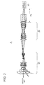
- Fig. 2 is an overall schematic diagram representing a magnified-projection optical system 4.
- the magnified-projection optical system 4 includes a projection optical system 10, relay optical system 20 and display element 30 which are arranged sequentially along the optical axis K1 in that order as viewed from the screen, and provides magnified-projection of the image outputted from the display element 30, on the screen.
- Fig. 3 is an overall schematic diagram representing a projection optical system 10.
- the projection optical system 10 projects the image primarily formed by the relay optical system, on the screen 1 in a magnified form, and includes a negative group G1 having a negative optical power, a positive group G2 having a positive optical power, seven lenses L9 through L15, and a stop S 1 arranged between the lenses L9 and L10, these components being arranged sequentially in that order as viewed from the screen 1.
- the negative group G1 includes the lens L1 through L4 arranged sequentially in that order as viewed from the screen.
- the lens L1 through L3 are negative meniscus lenses convexed to the screen 1.
- the lens L4 is a negative meniscus lens convened to the display element 30.
- the lens L1 through L3 correspond to an example of at least one negative meniscus lens of the negative group G1.
- the lens L4 corresponds to an example of at least one negative lens of the negative group G1.
- the positive group G2 includes four lenses L5 through L8.
- the lens L9 is a meniscus lens convened to the screen 1.
- the lens L10 is a double concave lens.
- the lens L11 is a double convex lens.
- the lens L12 is a double convex lens.
- the lens L13 is a double concave lens.
- the lenses L14 and L15 are double convex lenses.
- Fig. 3 shows three negative lenses convexed to the screen 1 contained in the negative group G1. Without the present invention being restricted thereto, it is only required that at least one negative meniscus lens should be located on the side of the screen 1.
- the lens L4 is shown as a negative lens contained in the negative group G1. Without the present invention being restricted thereto, it is only required that at least one negative lens should be included. Two or more negative lenses can be contained.
- the lenses L1 through L4 are shown as forming a negative group G1. Without being restricted thereto, other lenses can be included if a negative optical power is provided as a whole.
- the lenses L5 through L8 are shown as forming a positive group G2. Without being restricted thereto, other lenses can be included if a positive optical power is provided as a whole.
- the lenses L9 through L15 are included in addition to the negative group G1 and positive group G2. These lenses can be eliminated.
- Fig. 4 is an overall schematic diagram representing a relay optical system 20.
- the relay optical system 20 includes lenses L16 through L27 arranged in that order as viewed from the screen 1.
- the relay optical system 20 forms a primary image of an image outputted from the display element 30 and color-synthesized by the prism PR1, and outputs this image to the projection optical system 10.
- the lenses L16, L17, L19, L24, L26 and L27 are double convex lenses.
- the lens 20 is a meniscus lens convexed to the screen 1.
- the lens L23 is a meniscus lens convexed to the display element 30.
- the L18, L21, L22 and L25 are double concave lenses.
- the lenses L16 through L27 are symmetric with respect to the r44 representing a dummy surface.
- the prism PR1 is arranged between the lens L27 and display element 30.
- the prism PR1 color-synthesizes the image outputted from the display element 30 and outputs the resulting image to the relay optical system 20.
- a projection optical system having a wider angle namely, a projection optical system with a shorter focal distance is essential to ensure projection on a greater screen or a wide range of dome.
- This projection optical system requires a longer back focus for the following reasons:
- the entire size of the display element has been increased as a result of growing density in display element package.
- a greater power and greater size of the illumination system are essential to meet the demand for a brighter image.
- use of a reflective display element results in an increase in the size of the portion leading the illumination light to the display element.
- an image of higher definition is required to meet the growing density of display element package. This requires still higher performance of the projection optical system. To achieve the higher performance, the MTF performance must be enhanced. To enhance the MTF performance as well as definition, the chromatic aberration in particular must be reduced. To ensure projection over a wider range, the lateral chromatic aberration in particular should be completely correctly.
- the magnified-projection optical system 4 in the embodiment of the present invention is provided with a projection optical system 10, relay optical system 20 and display element 30 arranged in that order as viewed from the screen 1.
- the image from the display element 30 is subjected to primary image formation by the relay optical system 20.
- the primarily formed image is enlarged and projected by the projection optical system 10.
- a relay optical system 20 is placed between the projection optical system 10 and display element 30.
- a long back focus is provided by the relay optical system 20, whereby the back focus of the projection optical system 10 can be reduced and an increased angle of view can be ensured.
- This arrangement provides a magnified-projection optical system 4 characterized by a long back focus Fb in the entire optical system despite an increased angle of view.
- the projection optical system 10 can be implemented by a short back focus. This arrangement reduces the size in the radial direction of the projection optical system 10 on the side of the screen 1.
- the back focus Fb of the entire optical system is defined as the equivalent length in air on the optical axis from the vertex of surface P3 on the display element 30 side of the lens L27 closest to the display element 30 in the relay optical system 20, to the display element 30.
- the projection optical system 10 is a projection system characterized by a short back focus and an increased angle of view.
- the negative group G1 having a negative optical power is arranged at a position closest to the screen 1. This arrangement permits projection to be made over a wider range.
- the projection optical system 10, relay optical system 20 and display element 30 are arranged in that order as viewed from the side ofthe screen 1.
- this arrangement allows the entrance pupil to be arranged closer to the screen than the optical system composed of the projection optical system alone.
- This structure permits reduction in the effective diameter of the lens located closest to the screen 1. Hence, the size of the optical system in the radial direction is reduced.
- the lens of the negative group G1 closet to the screen 1 is characterized by great height of the off-axis light, and gives a serious impact to the off-axis performances such as distortion and lateral chromatic aberration.
- the lens closest to the screen 1 in the negative group G1 is preferably made up of a negative meniscus lens having a minimized angle of deflection with respect to the off-axis major light. Further, if the lens closest to the screen 1 in the negative group G1 is made of at least two negative lenses, the negative optical power is dispersed and the occurrence of the aberration can be suppressed.
- Lateral chromatic aberration occurs to the lens closest to the screen 1 in the negative group G1.
- a positive group G2 having the positive optical power is preferably arranged on the primary image forming surface side of the negative group G1 having the negative optical power.
- the lateral chromatic aberration occurring to the negative group G1 is cancelled out by the lateral chromatic aberration in the direction reverse to that occurring to the positive group G2.
- This arrangement provides a high-performance magnified-projection optical system 4 characterized by reduced lateral chromatic aberration.
- the magnified-projection optical system 4 preferably meets the following conditional expressions (1) and (2).
- Fb / F 10 0.5 ⁇ F / Fp ⁇ 2
- Fb is a back focus of the entire optical system including the projection optical system 10 and relay optical system 20
- F is a focal distance of the entire optical system
- Fp is a focal distance of the projection optical system 10.
- the conditional expression (1) defines the length of the back focus Fb.
- the conditional expression (1) defines the range wherein the structure using the relay optical system 20 is suited, when constituting the magnified-projection optical system 4 with the lateral chromatic aberration having been corrected. If the conditional expression (1) is met, the lateral chromatic aberration can be suppressed and the projection optical system 10 can be designed in a more compact configuration. It should be added that
- the conditional expression (2) defines the magnification of the relay optical system 20.
- the F/Fp of the conditional expression (2) indicates the magnification of the relay optical system 20, and represents the ratio of the display element 30 with respect to the primarily formed image of the relay optical system 20.
- the magnification of the relay optical system 20 has met the conditional expression (2), the balance is maintained between the brightness of the image projected on the screen I and the angle of view.
- conditional expression (2) when the magnification of the relay optical system 20 is increased, the focal distance Fp of the projection optical system 10 can be increased if the angle of view of the projection optical system 10 remains unchanged. This provides an advantage of the projection optical system 10 and makes it easier to enhance performances. However, to ensure amount of light required by the projection optical system 10, the brightness of the relay optical system 20 must be increased, and the Fno of the relay optical system 20 must be decreased. In the conditional expression (2), in the meantime, if the magnification ofthe relay optical system 20 is reduced, the Fno of the projection optical system 10 can be increased. This is advantageous. However, the height of the primarily formed image is reduced.
- conditional expression (2) provides a trade-offbalance between them. If the conditional expression (2) is satisfied, the performance can be enhanced without causing any difficulties in the reduction of the size of the magnified-projection optical system 4.
- the magnification of the relay optical system 20 comes close to 100% rate.
- the relay optical system 20 can be formed of a symmetric optical system so as to cut down the expenses for procuring and processing the glass material for the lens constituting the relay optical system 20.
- projection optical system 10 and relay optical system 20 are preferred to satisfy the following conditional expression (3):
- the Fp/Fm of the conditional expression (3) defines the focal distance Fm of the negative group G1 of the projection optical system 10.
- conditional expression (3) is preferred to be 0.6 ⁇
- At least one positive lens (L6 through L8 in Fig. 3 ) of the positive group G2 is preferred to be arranged closer to the screen 1 than where the off-axis major light K2 crosses the optical axis K1 at the position closest to the screen 1.
- the projection optical system 10 and relay optical system 20 preferably meet the following conditional expression (4):
- Yp is the maximum value for light height on the surface of the positive lens resulting from the off-axis paraxial tracing of the major light at a angle of view equivalent to 70 percent ofthe angle of view on the outermost portion, of the positive lenses (lenses L6 through L8) arranged closer to the screen 1 than where the off-axis major light K2 crosses the optical axis K1 at the position closest to the screen 1, in the positive group G2 of the projection optical system 10; and Ym is the minimum value for light height on the surface of the negative lens resulting from the off-axis paraxial tracing of the major light at a angle of view equivalent to 70 percent of the angle of view on the outermost portion, in the area wherein the negative lens constituting the negative group G1 of the projection optical system 10 is arranged.
- the height of the major light at an angle of view equivalent to 70 percent of the angle of view on the outermost portion indicates the distance from the optical axis K1 where the major light cross
- the positive group G2 preferably contains at least one positive lens meeting the following conditional expression (5):
- ⁇ pm is the Abbe's number of the lens having the greatest Abbe's number in the negative group G1 of the projection optical system 10
- vpp is the Abbe's number of the positive lens.
- the magnified-projection optical system 4 to ensure that the image from the relay optical system 20 is projected by the projection optical system 10, it is preferred to reduce the lateral chromatic aberration of the projection optical system 10 to ensure a high-performance projection image.
- the configuration of the present invention does not require a long back focus of the projection optical system 10.
- the positive group G2 is arranged after the negative group G1 located closest to the screen 1 in the projection optical system 10, it is possible to considerably cancel out the lateral chromatic aberration occurring to the negative lens inside the negative group G1 closest to the screen 1 in the projection optical system 10, by means of the positive lens having a positive optical power constituting positive group G2.
- the chromatic aberration occurring to the negative lens inside the negative group G1 is corrected by the chromatic aberration in the reverse direction which is generated by the positive lens inside the positive group G2.
- the lateral chromatic aberration occurring to the negative lens closest to the screen 1 in the negative group G1 should be corrected by the positive lens having positive optical power constituting the positive group G2.
- the direction of the lateral chromatic aberration occurring to the negative group G1 must be made equal to the direction where the lateral chromatic aberration occurs in the direction corrected by the positive lens of the positive group G2.
- At least one positive lens in the positive group G2 is preferably arranged closer to the screen 1 than where the off-axis major light K2 crosses the optical axis K1. This signifies that the major light passing through the negative group G1 closest to the screen 1 and the major light passing through although one lens of the negative group G1 travel in the same direction with respect to the optical axis K1. This arrangement allows the lateral chromatic aberration to be corrected by at least one positive lens.
- the power of the positive lens should be increased. If the power is increased, the lateral chromatic aberration generated in the reverse direction is generated with respect to the lateral chromatic aberration occurring to the negative lens of the negative group G1, so that the absolute value thereof can be made closer to the lateral chromatic aberration occurring to the negative lens of the negative group G1.
- the optical system of the present embodiment includes the projection optical system 10 and relay optical system 20 arranged in that order as viewed from the screen 1. This makes it possible to reduce the back focus of the projection optical system 10 when the light is traced from the side of the screen 1. This arrangement allows the optical power of the positive group G2 to be relatively increased, and permits the optical power of the positive lens to be increased.
- the composition of the projection optical system 10 and relay optical system 20 is advantageous to the correction of lateral chromatic aberration.
- the optical power of the positive lens is too strong, impact of the positive power on spherical aberration will be excessive, with the result that high-performances cannot be maintained.
- the power at the upper limit is not sufficient to ensure high-performance correction of lateral chromatic aberration.
- the structure of the projection optical system 10 and relay optical system 20 alone is not sufficient to ensure satisfactory correction of both the lateral chromatic aberration and spherical aberration.
- the lateral chromatic aberration correction capacity should be enhanced, without the positive optical power being very strong.
- the conditional expression (4) defines the height of the light for correction of the lateral chromatic aberration to a proper level.
- the optical system is composed of the projection optical system 10 and relay optical system 20 arranged in that order as viewed from the screen 1 and the projection optical system meets the conditional expression (1) and (2). This arrangement allows the back focus to be reduced when the light is traced from the side of the screen 1 of the projection optical system 10. This implement the configuration meeting the conditional expression (4).
- conditional expression (4) If the lower limit of the conditional expression (4) is exceeded, the height of the off-axis light of the positive lens of the positive group G2 can be ensured, and satisfactory correction of lateral chromatic aberration is ensured. If the value of the conditional expression (4) is smaller, the optical power of the positive lens must be increased. This tends to deteriorate the spherical aberration.
- the conditional expression (5) defines the scope of selecting the glass material and the scope of dispersion to optimize the lateral chromatic aberration. To put it more specifically, it defines the Abbe's number of glass. If the upper limit of the conditional expression (5) is exceeded and the Abbe's number of the positive lens is excessively reduced, the cancellation of the chromatic aberration by dispersion will be reduced and the chromatic aberration correction capacity will be reduced. In the meantime, if the lower limit of the conditional expression (5) cannot be reached, and the Abbe's number of the positive lens is excessively increased, the chromatic aberration correction capacity will be increased excessively. Thus, the chromatic aberration correction is optimized if the conditional expression (5) is satisfied.
- the relay optical system 20 forms an approximately telecentric optical system on the side of the display element 30.
- the approximately telecentric optical system preferably meets the following conditional expression (6)
- ⁇ max is the maximum angle formed between the normal line of the display element 30 and the major light traveling from the display element 30 to the relay optical system 20.
- the opening of the relay optical system 20 on the display element 30 side should be increased. However, if the opening is increased to excess, the aberration correction will become difficult. Further, the portion in excess of the opening angle of light on the display element 30 side does not contribute to the amount of light to be projected, and is hence wasted.
- the opening must be enlarged in order to receive the light from the display element 30, with the result that the size of the relay optical system 20 is increased.
- the relay optical system 20 should be made telecentric on the side of the display element 30.
- the conditional expression (6) defines the level of telecentricity. If the conditional expression (6) is satisfied, irregularities in the amount of light and loss of light can be reduced substantially More preferably, the conditional expression (6) is
- the relay optical system 20 is approximately telecentric on both sides, and this approximately telecentric optical system on both sides preferably meets the following conditional expression (7):
- ⁇ max is the maximum angle formed between the normal line of the surface wherein an image is primarily formed, and the main light passing through the surface wherein an image is primarily formed, from the side of the display element 30.
- the approximately telecentric optical system on both sides preferably meets the following conditional expression:
- ⁇ is the optical power of the relay optical system 20
- Tr is the distance from the vertex of surface P2 on the screen 1 side of the lens L16 closest to the screen 1 in the relay optical system 20, to the vertex of surface P3 on the display element 30 of the lens L27 located closest to the screen 1 (without including such a prism such as a color-synthesis prism).
- the relay optical system 20 side of the projection optical system 10 is made telecentric, and the opening of the relay optical system 20 on the screen 1 side is made the same as the opening of the projection optical system 10 on the relay optical system 20 side. This arrangement ensures an effective transfer of light from the relay optical system 20 to the projection optical system 10.
- the zoomed optical system should be used in normal cases.
- the zoomed optical system will inevitably become very large in size and very expensive, if the opening of the projection optical system 10 on the relay optical system 20 side is kept unchanged.
- the projection optical system 10 a plurality of unifocal optical systems which are telecentric and which have the same openings of the projection optical system 10 on the relay optical system 20 side and different focal distances are prepared, and the projection optical system 10 is exchanged.
- the magnification rate for projection can be changed at a reduced cost with the minimum loss in the amount of light.
- This structure permits the projection optical system 10 to be exchanged as an optical system having a plurality of focal distances, and ensures a satisfactory trade-off relationship between the cost and performance.
- conditional expression (7) together with the conditional expression (6) defines the level of double telecentricity of the relay optical system 20. If the conditional expression (7) is met, irregularities and loss in the amount of light can be reduced substantially.
- the conditional expression (7) is preferably
- the conditional expression (8) defines the double telecentricity of the relay optical system. To make the projection optical system 10 replaceable, the conditional expression (8) should be satisfied. Then variations in production with respect to the level of telecentricity of the projection optical system 10 can be kept within the normal scope, and less costly production of the projection optical system 10 can be achieved without having to increase the production cost thereof.
- the Tr is the distance from the vertex of surface P2 on the screen 1 side of the lens L16 closest to the screen 1in the relay optical system 20, to the vertex of surface P3 on the display element 30 side of the lens L27 on the side of the display element 30.
- the conditional expression (8) is preferably
- the angle of view of the entire optical system preferably meets the following conditional expression (A1):
- W is the angle of view of the entire optical system.
- a greater angle of view provides better projection.
- the image can be projected in a more enlarged size when the display element size remains unchanged.
- An image projected in a more enlarged size enhances presence.
- a shorter projection distance can be used when the same projection magnification rate is required. This ensures an effective use of space. In these respects, a wider angle of view is preferred. However, if an attempt is made to project the same display element at a wider view of angle, a shorter focal distance will be required. If an attempt is made to form an optical system at a shorter focal distance, it will become difficult to ensure the performances from the mid- to final-regions.
- the conditional expression (A1) should be satisfied.
- the angle of view is preferably close to 180 degrees.
- the upper limit of the conditional expression (A1) is preferably 200 degrees if the curvature of the lens L1 closest to the screen 1 in the projection optical system 10 is considered from the viewpoint of product cost and processability.
- the angle of view of the projection optical system 10 preferably meets the following conditional expression (A2).
- conditional expression (A2) defines the angle of view of the projection optical system 10 required to satisfy the aforementioned conditional expression (A1).
- the lower limit of the conditional expression (A2) is preferably 140 degrees, more preferably 155 degrees.
- a fisheye lens optical system is preferably used as a projection optical system 10. More preferably, an equi-distance projection, system (f• ⁇ ) should be used.
- the angle of view of about 150 degrees or more is required.
- a fisheye optical system is preferably used as the projection optical system 10. Adoption of the fisheye optical system permits projection on a wider area such as the whole sky. Further, if the distance on the display element 30 is proportional to the distance on the screen 1 in projection, use of the equi-distance projection system (f• ⁇ ) ensures more natural projection when the display element 30 is projected on the screen such as a dome.
- the position of the entrance pupil of the projection optical system 10 and the overall length of the projection optical system 10 preferably meet the following conditional expression (A3):
- Le indicates the distance from the vertex of surface of the lens L1 closest to the screen 1 in the projection optical system 10, to the entrance pupil when the light is traced from the screen I of the projection optical system 10 toward the display element 30; and TLp is the overall distance of the projection optical system 10 (from the vertex of surface of the lens L1 closest to the screen 1 in the projection optical system 10, to the vertex of surface of the lens L15 closest to the relay optical system 20).
- the conditional expression (A3) defines the position of the entrance pupil of the projection optical system 10.
- the optical system of the present embodiment includes the projection optical system 10 and relay optical system 20.
- the projection optical system 10 does not require such a long back focus.
- the position of the entrance pupil can be set close to the display element 3 0. Accordingly, if the conditional expression (A3) is met, the position of the light from the optical axis of the lens L1 can pass through a lower position, wherein this light is emitted from the lens L1 closest to the screen 1.
- conditional expression (A3) is preferably Le/TLp > 0.1 ... (A3a), more preferably Le/TLp > 0.15 ... (A3b). If this is satisfied, it is possible to further reduce the effective diameter of the lens L1 closest to the screen 1.
- the effective diameter of the lens L1 closest to the screen 1 in the projection optical system 10 and the focal distance of the projection optical system 10 preferably meet the following conditional expression (A4):
- D1 is the effective diameter of the lens L1 closest to the screen 1 in the projection optical system 10
- Fp is the focal distance of the projection optical system. 10.
- the entrance pupil can be placed closer to the screen 1 and the light from the optical axis of the light can pass through a lower position, wherein this light is emitted from the lens L1 closest to the screen 1. This allows the effective diameter of the lens L1 closest to the screen 1 to be reduced.
- the conditional expression (A4) defines the effect thereof. If the lower limit of the conditional expression (A3) cannot be reached, and the entrance pupil is located closer to the primary image side, the effective diameter of the lens L1 closest to the screen 1 will be increased excessively.
- the conditional expression (A4) is preferably Dl/Fp ⁇ 20 ... (A4a).
- the distance from the vertex of surface of the lens L15 closest to the relay optical system 20 in the projection optical system 10, to the primary image (back focus of the projection optical system 10), and the focal distance of the projection optical system 10 preferably meet the following conditional expression (A5).
- Fbp is the distance from the vertex of surface closest to the relay optical system 20 in the projection optical system 10, to the primary lineage
- Fp is the focal distance of the projection optical system 10.
- the back focus Fbp of the projection optical system 10 is preferably set so as to meet the conditional expression (A5).
- the conditional expression (A5) is preferably 5 > Fbp/Fp > 2 ... (A5a).
- An approximately telecentric optical system is located on the primary image side of the projection optical system 10. This approximately telecentric optical system preferably satisfies the following conditional expression (A6):
- conditional expression (A6) defines the both-side approximately telecentric optical system of the projection optical system 10.
- the relay optical system 20 side of the projection optical system 10 is made telecentric, and the opening of the relay optical system 20 on the side of the screen 1 is made the same as the opening of the projection optical system 10 on the side of the relay optical system 20. This arrangement ensures effective transmission of light from the relay optical system 20 to the projection optical system 10.
- a plurality of unifocal optical systems which have the same openings of the projection optical system 10 on the relay optical system 20 side and different focal distances are prepared, and the projection optical system 10 is exchanged.
- the projection optical system 10 as an optical system having a plurality of zooming ratio can be changed so that a trade-off relationship between cost and performance is maintained.
- irregularities and loss in the amount of light can be reduced substantially if the conditional expression (A6) is satisfied.
- the focal distance of the negative lens L1 closet to the screen 1 in the negative group G1 of the projection optical system 10 and the focal distance of the projection optical system 10 preferably satisfy the aforementioned conditional expression (A7).
- the negative lens L1 closest to the screen 1 in the negative group G1 of the projection optical system 10 is preferably a meniscus lens conveyed toward the screen 1 and belongs preferably to the spherical surface system.
- the conditional expression (A7) defines the negative optical power of the negative lens L1 closest to the screen I in the negative group G1 of the projection optical system 10. If the lens closest to the screen 1 is a lens having a positive optical power, the effective diameter will be increased too much although distortion problem can be solved. If the negative optical power of this lens is high, advantages can be obtained by increasing the projected angle of view. However, if the optical power becomes excessive, the negative distortion and lateral chromatic aberration will be excessive. Thus, the negative distortion and lateral chromatic aberration can be suppressed if the conditional expression (A7) is satisfied. When a meniscus lens convened toward the screen 1 is used as the negative lens L1, it is possible to suppress astigmatism and distortion effectively when the optical power is kept unchanged.
- conditional expression (A7) is preferably 50 > Fpm / Fp > 5
- the focal distances of the front and rear groups of the relay optical system 20 preferably satisfy the following conditional expression (A8):
- the relay optical system 20 is preferably as symmetric as possible. For this purpose, asymmetric configuration should be avoided whenever possible.
- the conditional expression (A8) represents collapse of the symmetry in the configuration of the relay optical system 20. When the conditional expression (A8) is satisfied, the symmetry and a tradeoff relationship of the optical power between the front and rear groups can be maintained. Correction of the lateral chromatic aberration is facilitated. It should be noted that the conditional expression (A8) is preferably 1.2 >
- the focal distance of the negative lens closest to the display element 1 in the relay optical system 20 and the focal distance of the entire optical system preferably satisfy the following conditional expression (A8):
- Frm / F 0.5 wherein Frm is the focal distance of the negative lens closest to the display element 1 in the relay optical system 20, and F is focal distance of the entire optical system.
- the conditional expression (A9) defines the optical power of the negative lens closest to the display element 1 in the relay optical system 20.
- the negative lens closest to the display element 1 in the relay optical system 20 does not mean that this lens is located closest to the screen 1 in the relay optical system 20.
- a positive lens can be placed on the screen 1 side of this negative lens.
- An approximately telecentric system on both sides is preferably used as the relay optical system 20. To get a telecentric system, a lens having a powerful negative power capable of leading light to a high position must be placed at some midpoint.
- the Abbe's number of the negative lens closest to the display element 30 in the relay optical system 20 preferably meets the following conditional expression (A10).
- conditional expression (A10) defines the dispersion of the negative lens closest to the display element 30 in the relay optical system 20.
- chromatic aberration must be very small.
- the negative lens is required to have a certain level of dispersion. Otherwise, the chromatic aberration occurring to the positive lens cannot be corrected. If the dispersion is reduced so that the upper limit of the conditional expression (A10) is exceeded, the chromatic aberration correction capacity will be reduced.
- conditional expression (A10) is preferably 55 > ⁇ rm > 35 ... (A10a).
- the relay optical system 20 is equipped with at least two low-dispersion lenses and the following conditional expression (A11) and (A12) are satisfied:
- ⁇ dr is a Abbe's number of the low-dispersion lens in the relay optical system 20
- Pgfr is the secondary dispersion of the low-dispersion lens in the relay optical system 20.
- ⁇ dr is a Abbe's number of the low-dispersion lens in the relay optical system 20
- Pgfr is the secondary dispersion of the low-dispersion lens in the relay optical system 20.
- the positive lens is preferably made of anomalous dispersion glass. However, this glass is somewhat more expensive than the normal glass.
- the number oflenses used is at least two, preferably six, more preferably eight or even more.
- the conditional expression (A11) defines the degree of dispersion of this lens. If the lower limit of the conditional expression (A11) cannot be reached, the degree of dispersion will be excessive and chromatic aberration correction capacity will be deteriorated. If a material exceeds the upper limit of the conditional expression (A11), such a material is an unknown one and is predicted to be very expensive. Thus, if the conditional expression (A11) is met, proper chromatic aberration correction can be achieved.
- conditional expression (A12) defines the anomalous dispersion of this lens. If the upper limit of the conditional expression (A12) is exceeded, the anomalous dispersion is reduced and satisfactory correction of the secondary chromatic aberration cannot be achieved. Thus, when the conditional expression (A12) is satisfied, the satisfactory correction of the secondary chromatic aberration cannot be achieved.
- the distance from the primary image formation point of the relay optical system 20 to the display element 30 and overall length of the entire optical system preferably meet the following conditional expression (A13).
- TLr1 is the distance from the primary image formation point, of the relay optical system 20 to the display element 30, and TL is the overall length of the entire optical system (wherein actual dimensions are used for the prism without being converted into the equivalent length in air).
- the distance from the vertex of surface P2 of the lens L16 closest to the screen 1 in the relay optical system 20 to the vertex of surface P3 of the lens L27 closest to the display element 30 preferably meets the following conditional expression (A14).
- TLr2 is the distance from the vertex of surface P2 of the lens L16 closest to the screen 1 in the relay optical system 20 to the vertex of surface P3 of the lens L27 closest to the display element 30, and TL is the entire optical system of the entire optical system (wherein actual dimensions are used for the prism without being converted into the equivalent length in air).
- the distance from the primary image formation point of the relay optical system 20 to the display element 30, and the distance from the vertex of surface P2 of the lens L16 closest to the screen 1 in the relay optical system 20, to the vertex of surface P3 of the lens L27 closest to the display element 30 preferably meet the following conditional expression (A15):
- TLr1 is a distance from the primary image formation point of the relay optical system 20 to the display element 30, and TLr2 is a distance from the vertex of surface P2 of the lens L16 closest to the screen 1 in the relay optical system 20.
- the conditional expressions (A13) through (A15) provide a rough indication thereof. If the value is excessive, the percent of the area occupied by the relay optical system 20 in the entire optical system will be increased. If the size of the entire optical system is to be included in the target, the size of the projection optical system 20 must be reduced.
- conditional expression (A13) is preferably 0.7 > TLrl/TL > 0.5 ...
- conditional expression (A13a) is preferably 0.4 > TLr2/TL > 0.1 ... (A14a).
- the conditional expression (A15) is preferably 0.6 > TLr2/TL1 > 0.3 ... (A15a).
- the projection optical system 10 includes a negative meniscus lens, negative meniscus lens and negative lenses (L1 through L14) arranged in that order as viewed from the screen 1. It is preferred to adopt a structure equipped with two, more preferably, three lenses (L11, L12, L14 and L15) having a positive optical power including the cemented lens on the side of the display element 30 in the stop S1.
- a negative meniscus lens, negative meniscus lens and negative lenses are arranged in that order as viewed from the screen 1, the astigmatism, distortion and lateral chromatic aberration can be effectively corrected.
- the somatic aberration can be corrected and telecentricity can be ensured effectively by adopting a structure equipped with two, more preferably, three lenses (L11, L12, L14 and L15) having a positive optical power including the cemented lens on the side of the display element 30 in the stop S1.
- the relay optical system 20 should be approximately symmetric and the relay magnification rate should be 100%.
- the magnification rate of the relay optical system 20 is 100% and a symmetric structure is adopted, the comatic aberration and lateral chromatic aberration can be reduced. Further, many advantages can be provided. For example, stabilization of the components and cutdown of the production cost can be achieved.
- the relay optical system 20 is arranged in the order of positive, negative, positive, negative, positive, negative and positive. Preferred is the positive, positive, negative, positive, positive, negative, negative, positive, positive, negative, positive and positive arrangement in that order as viewed from the screen 1.
- the projection optical system 10 should be made of 13 lenses (where the number of cemented lenses is counted after separating them into each single lens), and the relay optical system 20 should be made of 12 lenses.
- the number of lenses used is preferably increased. However, if the number of lenses is excessive, the transmittance will be deteriorated by reflection on the surface of each lens, the system cannot be put into commercial use. Accordingly, as described above, the numbers of the lenses in the projection optical system 10 and relay optical system 20 should be designed approximately the same with each other.
- the major light having the maximum angle of view passing through at least one positive lens in the positive group G2 of the projection optical system 10, and the major light having the maximum angle of view passing through the lens closest to the screen 1 in the negative group G1 of the projection optical system 10 preferably travel in the same direction with respect to optical axis, and preferably meet the following conditional expression (B1):
- ⁇ Rp is the maximum of the effective diameters of the positive lens of the positive group G2 in the projection optical system 10
- ⁇ Rn is the effective diameter on the screen 1 side of the negative lens closest to the screen 1 in the projection optical system 10.
- B2 conditional expression
- ⁇ Rp is the maximum of the elective diameters of the positive lens of the positive group G2 in the projection optical system 10
- ⁇ fp is the focal distance of at least one positive lens in the positive group G2 of the projection optical system 10.
- the conditional expression (B1) defines the optimum conditions for ensuring effective correction of the chromatic aberration, particularly the lateral chromatic aberration. It should be noted that the following description assumes that light enters the screen 1 to travel toward the display element 30.
- chromatic aberration is corrected by mutual cancellation between the chromatic aberrations in the reverse directions occurring to positive lens and negative lens.
- the lateral chromatic aberration is also corrected in the similar manner. It is necessary to take into account the direction of the passing off-axis light with respect to the on-axis light. If the off-axis light travels in the same direction with respect to the optical axis, the lateral chromatic aberration occurring to the negative lens can be corrected by the lateral chromatic aberration occurring in the reverse direction due to the positive lens.
- the generation af the lateral chromatic aberration is normally greater when the optical power is greater.
- the optical power of the positive lens in the positive group G2 should be increased in order to correct the lateral chromatic aberration produced by the negative lens closest to the screen 1 in the negative group G1.
- the optical power of this positive lens is increased, the lateral chromatic aberration can be effectively corrected.
- the structure of the present invention consisting of the projection optical system 10 and relay optical system 20 permits reduction of the back focus Fbp in the projection optical system 10, as described above.
- the optical power of the positive lens in the positive group G2 can be relatively increased. However, if the optical power is excessive, other aberrations, especially spherical aberration and astigmatism, will be increased and the image performance will be deteriorated. This requires the optical power to be set to a proper level.
- the projection optical system 10 of the present embodiment adopts the so-called retro-focus type having a negative optical power on the side of the screen 1 and a positive optical power on the side of the display element 1.
- a stop P1 is provided in the midway of the optical system so that the optical power is provided on the side of the display element 30.
- the direction of the lateral chromatic aberration occurring to the positive lens closer to the display element 30 than the stop P 1 is different from the direction of the lateral chromatic aberration occurring to the positive group G2 located before the stop P1.
- the off-axis light of the positive lens closer to the display element 30 than the stop P1 has an off-axis light in the direction reverse to that of the negative lens on the display element 1 side.
- the positive lens located closer to the display element 30 than the stop P 1 generates the chromatic aberration in the direction of increasing the lateral chromatic aberration that occurs to the negative lens closest to the display element 1 in the negative group G1.
- a high level of reverse lateral chromatic aberration must be produced using the direction wherein the off-axis light passes through the negative lens closest to the display element 1 with respect to the on-axis light, and at least one positive lens of the positive group G2 wherein the off-axis light in the same direction therewith passes.
- On-axis chromatic aberration must also be corrected.
- the direction in which on-axis chromatic aberration occurs in the same direction for a positive lens.
- the on-axis chromatic aberrations occurring to the positive lenses before and after the stop P1 with respect to the screen 1 are in the same direction, as in the case of the lateral chromatic aberration.
- the optical power of this positive lens is increased to an excels, a heavy on-axis chromatic aberration will be produced, and a high-performance projected image cannot be obtained.
- the effective diameter ⁇ Rp can be increased.
- a negative lens having a very high optical power is arranged closest to the display element 30 in the negative group G1 or closest to the screen 1 in the positive group G2
- the off-axis light entering the positive lens can be shifted away from the optical axis K1.
- the effective diameter ⁇ Rp of the positive lens can be increased.
- a negative meniscus lens concaved to the screen I is used instead of this negative lens, the effective diameter ⁇ Rp of the positive lens can be increased without having to increase the negative optical power very much. In any way, the effective diameter ⁇ Rp of the positive lens can be increased. This ensures more effective correction of the lateral chromatic aberration.
- the conditional expression (B1) defines the effective diameter ⁇ Rp, and provides a very effective way of correcting the later chromatic aberration. Especially, this expression defines the effective diameter ⁇ Rp of this positive lens with respect to the effective diameter ⁇ Rn of the negative lens closest to the screen 1. It provides the conditions for correcting the lateral chromatic aberration more effectively by this positive lens, wherein this lateral chromatic aberration is produced by the negative group G1 closest to the screen 1. If the lower limit of the conditional expression (B1) cannot be reached and the effective diameter ⁇ Rp is small, satisfactory correction of the lateral chromatic aberration cannot be achieved.
- conditional expression (B1) is satisfied, optimization will be made to correct the lateral chromatic aberration and astigmatism. It should be noted that the conditional expression (B1) is preferably, 0.7 > ⁇ Rp/ ⁇ Rn> 0.4 ... (B1a).
- the conditional expression (B2) defines the relationship between the optical power of the positive lens and effective diameter ⁇ Rp, wherein focal distance is used as optical power. If the lower limit of the conditional expression (B2) cannot be reached and the focal distance fp of the positive lens is increased, namely, if the optical power is reduced and the effective diameter ⁇ Rp is increased excessively, the size of the lens must be increased.
- conditional expression (B2) is satisfied, effective correction of the aberration and suburb processability can be ensured. It should be noted that the conditional expression (B2) is preferably 2 > ⁇ Rp/fp > 0.2 ... (B2a).
- the magnified-projection optical system 4 is designed to have the aforementioned structure, the back focus is long enough to cope with an increase in the size of the display element and illumination system, and to allow a wide-angle video image to be projected. Further, the chromatic aberration can also be reduced, with the result that a high-performance digital type planetarium device can be implemented.
- the structure of the first Example is the same as those of Figs. 2 through 4 .
- Example 1 Numerical value of Example 1 Unit: mm Surface data Surface number: r d nd vd Screen: 6250.000 6250.00 1 116.336 6.00 1.51680 64.20 2 43.902 13.95 3 110.039 3.34 1.62041 60.34 4 26.322 4.45 5 363.038 2.60 1.65844 50.85 6 23.891 14.50 7 -26.799 2.30 1.74400 44.90 8 -82.792 12.05 9 -52.611 2.23 1.80518 25.46 10 457.099 1.60 11 554.594 10.80 1.60342 38.01 12 -35.417 0.20 13 2085.784 6.15 1.60342 38.01 14 -69.000 0.20 15 50.030 7.60 1.51680 64.20 16 -498.560 31.30 17 13.444 2.30 1.75520 27.53 18 10.311 10.40 19 (stop) ⁇ 1.80 20 -141.634 1.861.74400 44.90 21 16.011 2.83 1.51680
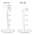
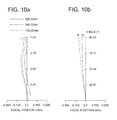
- Fig. 5 shows the aberration diagram of the magnified-projection optical system in the first Example based on the aforementioned lens arrangement and structure.
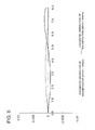
- Fig. 6 shows the lateral chromatic aberration of the magnified-projection optical system in the first Example.
- Fig. 5a shows the spherical aberration (SA), and
- Fig. 5b shows astigmatism (DS-DM).
- SA spherical aberration
- DS-DM astigmatism
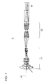
- Fig. 7 overall schematic diagram representing the magnified-projection optical system.
- the magnified-projection optical system 4 of the second Example includes a projection optical system 10, relay optical system 20 and display element 30 sequentially arranged along the optical axis K1 in that order as viewed from the screen 1, similarly to the case of Fig. 2 .
- Fig. 8 is the overall schematic diagram representing the projection optical system 10.
- Fig. 9 is the overall schematic diagram representing the relay optical system 20 in the second Example. As will be apparent from comparison with Fig. 4 , in the relay optical system 20 of Fig. 9 , the length of the prism PR1 in the direction of optical axis K1 is greater than that of Fig. 4 .
- Example 2 Unit Numerical value of Example 2 Unit: mm Surface data Surface number: r d nd vd Screen: 6250.000 6250.00 1 95.304 5.37 1.51680 64.20 2 37.873 12.88 3 88.754 3.02 1.62041 60.34 4 24.357 12.79 5 182.335 2.35 1.65844 50.85 6 20.257 12.93 7 -24.875 2.01 1.74400 44.90 8 -281.494 10.53 9 -79.050 2.01 1.80518 25.46 10 219.537 1.37 11 240.395 10.17 1.60342 38.01 12 -31.592 0.07 13 243.462 4.92 1.60342 38.01 14 -93.196 0.07 15 38.484 6.90 1.51680 64.20 16 718.601 23.83 17 13.942 2.01 1.75520 27.53 18 10.166 9.45 19 (stop) ⁇ 1.33 20 2872.660 1.68 1.74400 44.90 21 14.802 2.93
Landscapes
- Physics & Mathematics (AREA)
- General Physics & Mathematics (AREA)
- Optics & Photonics (AREA)
- Engineering & Computer Science (AREA)
- Astronomy & Astrophysics (AREA)
- Business, Economics & Management (AREA)
- Educational Administration (AREA)
- Educational Technology (AREA)
- Theoretical Computer Science (AREA)
- Lenses (AREA)
Applications Claiming Priority (2)
| Application Number | Priority Date | Filing Date | Title |
|---|---|---|---|
| JP2008050819 | 2008-02-29 | ||
| PCT/JP2009/053013 WO2009107553A1 (ja) | 2008-02-29 | 2009-02-20 | 拡大投影光学系及びデジタル式プラネタリウム装置 |
Publications (3)
| Publication Number | Publication Date |
|---|---|
| EP2249193A1 true EP2249193A1 (de) | 2010-11-10 |
| EP2249193A4 EP2249193A4 (de) | 2012-03-07 |
| EP2249193B1 EP2249193B1 (de) | 2022-12-28 |
Family
ID=41015950
Family Applications (1)
| Application Number | Title | Priority Date | Filing Date |
|---|---|---|---|
| EP09715446.2A Active EP2249193B1 (de) | 2008-02-29 | 2009-02-20 | Optisches system mit vergrösserter projektion und digitales planetarium |
Country Status (4)
| Country | Link |
|---|---|
| US (1) | US8270074B2 (de) |
| EP (1) | EP2249193B1 (de) |
| JP (1) | JP5625904B2 (de) |
| WO (1) | WO2009107553A1 (de) |
Families Citing this family (23)
| Publication number | Priority date | Publication date | Assignee | Title |
|---|---|---|---|---|
| US8270074B2 (en) | 2008-02-29 | 2012-09-18 | Konica Minolta Opto, Inc. | Magnified-projection optical system and digital type planetarium device |
| JP5823258B2 (ja) * | 2011-11-02 | 2015-11-25 | 日東光学株式会社 | 投射用レンズシステムおよび投影装置 |
| CN204065540U (zh) * | 2012-02-09 | 2014-12-31 | 富士胶片株式会社 | 投影用光学系统和投影型显示装置 |
| JP6290804B2 (ja) | 2015-02-25 | 2018-03-07 | 富士フイルム株式会社 | 投写用光学系および投写型表示装置 |
| JP6342828B2 (ja) | 2015-02-25 | 2018-06-13 | 富士フイルム株式会社 | 投写用光学系および投写型表示装置 |
| JP6352832B2 (ja) * | 2015-02-25 | 2018-07-04 | 富士フイルム株式会社 | 投写用光学系および投写型表示装置 |
| JP6280063B2 (ja) | 2015-02-25 | 2018-02-14 | 富士フイルム株式会社 | 投写用光学系および投写型表示装置 |
| JP6342827B2 (ja) * | 2015-02-25 | 2018-06-13 | 富士フイルム株式会社 | 投写用光学系および投写型表示装置 |
| CN208060922U (zh) | 2015-09-29 | 2018-11-06 | 富士胶片株式会社 | 投影镜头及投影仪 |
| JP6657863B2 (ja) * | 2015-12-01 | 2020-03-04 | コニカミノルタ株式会社 | 投影光学系及びプロジェクター |
| JP6973519B2 (ja) * | 2015-12-01 | 2021-12-01 | コニカミノルタ株式会社 | 投影光学系及びプロジェクター |
| JP6595405B2 (ja) | 2016-05-25 | 2019-10-23 | 富士フイルム株式会社 | 結像光学系、投写型表示装置、および、撮像装置 |
| JP7045611B2 (ja) * | 2017-03-29 | 2022-04-01 | パナソニックIpマネジメント株式会社 | レンズ系、レンズ系を有する画像投写装置及び撮像装置 |
| US10816780B2 (en) | 2017-03-29 | 2020-10-27 | Panasonic Intellectual Property Management Co., Ltd. | Lens system, and image projection apparatus and imaging apparatus that include the same |
| JP6755227B2 (ja) | 2017-09-25 | 2020-09-16 | 富士フイルム株式会社 | 結像レンズ、投写型表示装置、および撮像装置 |
| JPWO2019124082A1 (ja) * | 2017-12-19 | 2021-01-28 | パナソニックIpマネジメント株式会社 | 投写レンズ系及び画像投写装置 |
| US10838179B2 (en) * | 2018-02-28 | 2020-11-17 | Fujifilm Corporation | Wide-angle lens, projection lens, relay lens, projection-type display apparatus, and relay lens unit |
| JP6791322B2 (ja) * | 2019-08-27 | 2020-11-25 | コニカミノルタ株式会社 | 投影光学系及びプロジェクター |
| JP7020531B2 (ja) * | 2020-10-29 | 2022-02-16 | コニカミノルタ株式会社 | 投影光学系及びプロジェクター |
| JP7306369B2 (ja) * | 2020-12-24 | 2023-07-11 | セイコーエプソン株式会社 | 投写光学系、およびプロジェクター |
| CN112882219B (zh) * | 2021-01-23 | 2022-02-22 | 中国科学院长春光学精密机械与物理研究所 | 一种焦比可调的主动光学系统和方法 |
| US12313964B1 (en) | 2024-02-07 | 2025-05-27 | Miller Engineering, LLC | Home planetarium projection system with optical zoom lens |
| CN119270487B (zh) * | 2024-12-10 | 2025-02-28 | 成都优视光电技术有限公司 | 一种大光圈大靶面高分辨率近摄的自动对焦光学镜头 |
Family Cites Families (13)
| Publication number | Priority date | Publication date | Assignee | Title |
|---|---|---|---|---|
| US4070098A (en) * | 1976-04-28 | 1978-01-24 | The University Of Arizona Foundation | Fisheye projection lens system for 35mm motion pictures |
| JPH0469611A (ja) | 1990-07-10 | 1992-03-04 | Minolta Camera Co Ltd | 魚眼レンズ系 |
| JP2002131637A (ja) | 2000-10-30 | 2002-05-09 | Nikon Corp | リレー光学系 |
| JP2005509178A (ja) * | 2001-03-29 | 2005-04-07 | エリュメンス・コーポレイション | 光学的投影システム及び方法 |
| US7009765B2 (en) | 2002-08-16 | 2006-03-07 | Infocus Corporation | Wide angle lens system having a distorted intermediate image |
| US7090354B2 (en) | 2002-08-16 | 2006-08-15 | Infocus Corporation | Projection device and screen |
| US7342402B2 (en) * | 2003-04-10 | 2008-03-11 | Formfactor, Inc. | Method of probing a device using captured image of probe structure in which probe tips comprise alignment features |
| JP2005128286A (ja) | 2003-10-24 | 2005-05-19 | Olympus Corp | 超広角レンズ光学系及びそれを備えた撮像装置と表示装置 |
| JP2005221955A (ja) | 2004-02-09 | 2005-08-18 | Fujinon Corp | 魚眼レンズおよびこれを用いた投写型表示装置 |
| JP2006330410A (ja) | 2005-05-27 | 2006-12-07 | Hitachi Ltd | 投写光学ユニット及びそれを用いた投写型映像表示装置 |
| JP4926476B2 (ja) | 2006-01-11 | 2012-05-09 | コニカミノルタプラネタリウム株式会社 | デジタル式プラネタリウム装置 |
| US7621647B1 (en) * | 2006-06-23 | 2009-11-24 | The Elumenati, Llc | Optical projection system and method of use |
| US8270074B2 (en) | 2008-02-29 | 2012-09-18 | Konica Minolta Opto, Inc. | Magnified-projection optical system and digital type planetarium device |
-
2009
- 2009-02-20 US US12/919,080 patent/US8270074B2/en active Active
- 2009-02-20 EP EP09715446.2A patent/EP2249193B1/de active Active
- 2009-02-20 WO PCT/JP2009/053013 patent/WO2009107553A1/ja not_active Ceased
- 2009-02-20 JP JP2010500667A patent/JP5625904B2/ja active Active
Also Published As
| Publication number | Publication date |
|---|---|
| EP2249193B1 (de) | 2022-12-28 |
| EP2249193A4 (de) | 2012-03-07 |
| WO2009107553A1 (ja) | 2009-09-03 |
| US20110002034A1 (en) | 2011-01-06 |
| JPWO2009107553A1 (ja) | 2011-06-30 |
| JP5625904B2 (ja) | 2014-11-19 |
| US8270074B2 (en) | 2012-09-18 |
Similar Documents
| Publication | Publication Date | Title |
|---|---|---|
| EP2249193B1 (de) | Optisches system mit vergrösserter projektion und digitales planetarium | |
| US10890742B2 (en) | Projection optical system and projection type display device | |
| US10620413B2 (en) | Projection optical system and projection type display device | |
| US8213091B2 (en) | Wide-angle projection zoom lens and projection display device | |
| US8896929B2 (en) | Projection zoom lens and projection type display device | |
| US9557538B2 (en) | Projection zoom lens and projection type display device | |
| US9195034B2 (en) | Lens for projection and projection-type display apparatus | |
| US9541743B2 (en) | Projection zoom lens and projection type display device | |
| US9739989B2 (en) | Projection zoom lens and projection type display device | |
| US9664884B2 (en) | Projection zoom lens and projection type display device | |
| US8922903B2 (en) | Projection zoom lens and projection type display device | |
| US8967812B2 (en) | Projection optical system and projection display apparatus | |
| US7911705B2 (en) | Projection lens and projector | |
| JP6784563B2 (ja) | 投射用ズームレンズおよび投射型画像表示装置 | |
| JP4097957B2 (ja) | 広角ズームレンズおよびこれを用いた投写型表示装置 | |
| JP4222408B2 (ja) | ズームレンズ及びプロジェクタ | |
| US20180059391A1 (en) | Zoom lens, projection display device, and imaging apparatus | |
| US9772477B2 (en) | Projection zoom lens and projection type display device | |
| JP2004252084A (ja) | 投射用ズームレンズおよび拡大投射装置 | |
| JP2004138640A (ja) | 投射用ズームレンズ | |
| JPH11326763A (ja) | ズームレンズ及びそれを用いた投影装置 | |
| JP4530259B2 (ja) | ズームレンズおよびこれを用いた投写型表示装置 | |
| JP4810075B2 (ja) | ズームレンズ及びそれを有する画像投射装置 | |
| US20220107484A1 (en) | Projection zoom lens and projection device | |
| JPH07270680A (ja) | レトロフォーカス型レンズ |
Legal Events
| Date | Code | Title | Description |
|---|---|---|---|
| PUAI | Public reference made under article 153(3) epc to a published international application that has entered the european phase |
Free format text: ORIGINAL CODE: 0009012 |
|
| 17P | Request for examination filed |
Effective date: 20100824 |
|
| AK | Designated contracting states |
Kind code of ref document: A1 Designated state(s): AT BE BG CH CY CZ DE DK EE ES FI FR GB GR HR HU IE IS IT LI LT LU LV MC MK MT NL NO PL PT RO SE SI SK TR |
|
| AX | Request for extension of the european patent |
Extension state: AL BA RS |
|
| DAX | Request for extension of the european patent (deleted) | ||
| A4 | Supplementary search report drawn up and despatched |
Effective date: 20120207 |
|
| RIC1 | Information provided on ipc code assigned before grant |
Ipc: G02B 13/00 20060101AFI20120201BHEP Ipc: G02B 13/22 20060101ALI20120201BHEP Ipc: G03B 21/14 20060101ALI20120201BHEP |
|
| STAA | Information on the status of an ep patent application or granted ep patent |
Free format text: STATUS: EXAMINATION IS IN PROGRESS |
|
| 17Q | First examination report despatched |
Effective date: 20170614 |
|
| REG | Reference to a national code |
Ref country code: DE Ref legal event code: R079 Ref document number: 602009064723 Country of ref document: DE Free format text: PREVIOUS MAIN CLASS: G02B0013000000 Ipc: G02B0013060000 |
|
| GRAP | Despatch of communication of intention to grant a patent |
Free format text: ORIGINAL CODE: EPIDOSNIGR1 |
|
| STAA | Information on the status of an ep patent application or granted ep patent |
Free format text: STATUS: GRANT OF PATENT IS INTENDED |
|
| RIC1 | Information provided on ipc code assigned before grant |
Ipc: G02B 13/22 20060101ALI20220824BHEP Ipc: G09B 27/00 20060101ALI20220824BHEP Ipc: G02B 13/06 20060101AFI20220824BHEP |
|
| INTG | Intention to grant announced |
Effective date: 20220928 |
|
| GRAS | Grant fee paid |
Free format text: ORIGINAL CODE: EPIDOSNIGR3 |
|
| GRAA | (expected) grant |
Free format text: ORIGINAL CODE: 0009210 |
|
| STAA | Information on the status of an ep patent application or granted ep patent |
Free format text: STATUS: THE PATENT HAS BEEN GRANTED |
|
| AK | Designated contracting states |
Kind code of ref document: B1 Designated state(s): AT BE BG CH CY CZ DE DK EE ES FI FR GB GR HR HU IE IS IT LI LT LU LV MC MK MT NL NO PL PT RO SE SI SK TR |
|
| REG | Reference to a national code |
Ref country code: GB Ref legal event code: FG4D |
|
| REG | Reference to a national code |
Ref country code: CH Ref legal event code: EP |
|
| REG | Reference to a national code |
Ref country code: DE Ref legal event code: R096 Ref document number: 602009064723 Country of ref document: DE |
|
| REG | Reference to a national code |
Ref country code: AT Ref legal event code: REF Ref document number: 1540848 Country of ref document: AT Kind code of ref document: T Effective date: 20230115 |
|
| REG | Reference to a national code |
Ref country code: IE Ref legal event code: FG4D |
|
| REG | Reference to a national code |
Ref country code: LT Ref legal event code: MG9D |
|
| PG25 | Lapsed in a contracting state [announced via postgrant information from national office to epo] |
Ref country code: SE Free format text: LAPSE BECAUSE OF FAILURE TO SUBMIT A TRANSLATION OF THE DESCRIPTION OR TO PAY THE FEE WITHIN THE PRESCRIBED TIME-LIMIT Effective date: 20221228 Ref country code: NO Free format text: LAPSE BECAUSE OF FAILURE TO SUBMIT A TRANSLATION OF THE DESCRIPTION OR TO PAY THE FEE WITHIN THE PRESCRIBED TIME-LIMIT Effective date: 20230328 Ref country code: LT Free format text: LAPSE BECAUSE OF FAILURE TO SUBMIT A TRANSLATION OF THE DESCRIPTION OR TO PAY THE FEE WITHIN THE PRESCRIBED TIME-LIMIT Effective date: 20221228 Ref country code: FI Free format text: LAPSE BECAUSE OF FAILURE TO SUBMIT A TRANSLATION OF THE DESCRIPTION OR TO PAY THE FEE WITHIN THE PRESCRIBED TIME-LIMIT Effective date: 20221228 |
|
| REG | Reference to a national code |
Ref country code: NL Ref legal event code: MP Effective date: 20221228 |
|
| REG | Reference to a national code |
Ref country code: AT Ref legal event code: MK05 Ref document number: 1540848 Country of ref document: AT Kind code of ref document: T Effective date: 20221228 |
|
| PG25 | Lapsed in a contracting state [announced via postgrant information from national office to epo] |
Ref country code: LV Free format text: LAPSE BECAUSE OF FAILURE TO SUBMIT A TRANSLATION OF THE DESCRIPTION OR TO PAY THE FEE WITHIN THE PRESCRIBED TIME-LIMIT Effective date: 20221228 Ref country code: HR Free format text: LAPSE BECAUSE OF FAILURE TO SUBMIT A TRANSLATION OF THE DESCRIPTION OR TO PAY THE FEE WITHIN THE PRESCRIBED TIME-LIMIT Effective date: 20221228 Ref country code: GR Free format text: LAPSE BECAUSE OF FAILURE TO SUBMIT A TRANSLATION OF THE DESCRIPTION OR TO PAY THE FEE WITHIN THE PRESCRIBED TIME-LIMIT Effective date: 20230329 |
|
| P01 | Opt-out of the competence of the unified patent court (upc) registered |
Effective date: 20230510 |
|
| PG25 | Lapsed in a contracting state [announced via postgrant information from national office to epo] |
Ref country code: NL Free format text: LAPSE BECAUSE OF FAILURE TO SUBMIT A TRANSLATION OF THE DESCRIPTION OR TO PAY THE FEE WITHIN THE PRESCRIBED TIME-LIMIT Effective date: 20221228 |
|
| PG25 | Lapsed in a contracting state [announced via postgrant information from national office to epo] |
Ref country code: RO Free format text: LAPSE BECAUSE OF FAILURE TO SUBMIT A TRANSLATION OF THE DESCRIPTION OR TO PAY THE FEE WITHIN THE PRESCRIBED TIME-LIMIT Effective date: 20221228 Ref country code: PT Free format text: LAPSE BECAUSE OF FAILURE TO SUBMIT A TRANSLATION OF THE DESCRIPTION OR TO PAY THE FEE WITHIN THE PRESCRIBED TIME-LIMIT Effective date: 20230428 Ref country code: ES Free format text: LAPSE BECAUSE OF FAILURE TO SUBMIT A TRANSLATION OF THE DESCRIPTION OR TO PAY THE FEE WITHIN THE PRESCRIBED TIME-LIMIT Effective date: 20221228 Ref country code: EE Free format text: LAPSE BECAUSE OF FAILURE TO SUBMIT A TRANSLATION OF THE DESCRIPTION OR TO PAY THE FEE WITHIN THE PRESCRIBED TIME-LIMIT Effective date: 20221228 Ref country code: CZ Free format text: LAPSE BECAUSE OF FAILURE TO SUBMIT A TRANSLATION OF THE DESCRIPTION OR TO PAY THE FEE WITHIN THE PRESCRIBED TIME-LIMIT Effective date: 20221228 Ref country code: AT Free format text: LAPSE BECAUSE OF FAILURE TO SUBMIT A TRANSLATION OF THE DESCRIPTION OR TO PAY THE FEE WITHIN THE PRESCRIBED TIME-LIMIT Effective date: 20221228 |
|
| PG25 | Lapsed in a contracting state [announced via postgrant information from national office to epo] |
Ref country code: SK Free format text: LAPSE BECAUSE OF FAILURE TO SUBMIT A TRANSLATION OF THE DESCRIPTION OR TO PAY THE FEE WITHIN THE PRESCRIBED TIME-LIMIT Effective date: 20221228 Ref country code: PL Free format text: LAPSE BECAUSE OF FAILURE TO SUBMIT A TRANSLATION OF THE DESCRIPTION OR TO PAY THE FEE WITHIN THE PRESCRIBED TIME-LIMIT Effective date: 20221228 Ref country code: IS Free format text: LAPSE BECAUSE OF FAILURE TO SUBMIT A TRANSLATION OF THE DESCRIPTION OR TO PAY THE FEE WITHIN THE PRESCRIBED TIME-LIMIT Effective date: 20230428 |
|
| PG25 | Lapsed in a contracting state [announced via postgrant information from national office to epo] |
Ref country code: MC Free format text: LAPSE BECAUSE OF FAILURE TO SUBMIT A TRANSLATION OF THE DESCRIPTION OR TO PAY THE FEE WITHIN THE PRESCRIBED TIME-LIMIT Effective date: 20221228 |
|
| REG | Reference to a national code |
Ref country code: CH Ref legal event code: PL Ref country code: DE Ref legal event code: R097 Ref document number: 602009064723 Country of ref document: DE |
|
| REG | Reference to a national code |
Ref country code: BE Ref legal event code: MM Effective date: 20230228 |
|
| PG25 | Lapsed in a contracting state [announced via postgrant information from national office to epo] |
Ref country code: LU Free format text: LAPSE BECAUSE OF NON-PAYMENT OF DUE FEES Effective date: 20230220 Ref country code: LI Free format text: LAPSE BECAUSE OF NON-PAYMENT OF DUE FEES Effective date: 20230228 Ref country code: DK Free format text: LAPSE BECAUSE OF FAILURE TO SUBMIT A TRANSLATION OF THE DESCRIPTION OR TO PAY THE FEE WITHIN THE PRESCRIBED TIME-LIMIT Effective date: 20221228 Ref country code: CH Free format text: LAPSE BECAUSE OF NON-PAYMENT OF DUE FEES Effective date: 20230228 |
|
| PLBE | No opposition filed within time limit |
Free format text: ORIGINAL CODE: 0009261 |
|
| STAA | Information on the status of an ep patent application or granted ep patent |
Free format text: STATUS: NO OPPOSITION FILED WITHIN TIME LIMIT |
|
| 26N | No opposition filed |
Effective date: 20230929 |
|
| REG | Reference to a national code |
Ref country code: IE Ref legal event code: MM4A |
|
| PG25 | Lapsed in a contracting state [announced via postgrant information from national office to epo] |
Ref country code: SI Free format text: LAPSE BECAUSE OF FAILURE TO SUBMIT A TRANSLATION OF THE DESCRIPTION OR TO PAY THE FEE WITHIN THE PRESCRIBED TIME-LIMIT Effective date: 20221228 Ref country code: IE Free format text: LAPSE BECAUSE OF NON-PAYMENT OF DUE FEES Effective date: 20230220 |
|
| PG25 | Lapsed in a contracting state [announced via postgrant information from national office to epo] |
Ref country code: BE Free format text: LAPSE BECAUSE OF NON-PAYMENT OF DUE FEES Effective date: 20230228 |
|
| PG25 | Lapsed in a contracting state [announced via postgrant information from national office to epo] |
Ref country code: IT Free format text: LAPSE BECAUSE OF FAILURE TO SUBMIT A TRANSLATION OF THE DESCRIPTION OR TO PAY THE FEE WITHIN THE PRESCRIBED TIME-LIMIT Effective date: 20221228 |
|
| PG25 | Lapsed in a contracting state [announced via postgrant information from national office to epo] |
Ref country code: BG Free format text: LAPSE BECAUSE OF FAILURE TO SUBMIT A TRANSLATION OF THE DESCRIPTION OR TO PAY THE FEE WITHIN THE PRESCRIBED TIME-LIMIT Effective date: 20221228 |
|
| PG25 | Lapsed in a contracting state [announced via postgrant information from national office to epo] |
Ref country code: BG Free format text: LAPSE BECAUSE OF FAILURE TO SUBMIT A TRANSLATION OF THE DESCRIPTION OR TO PAY THE FEE WITHIN THE PRESCRIBED TIME-LIMIT Effective date: 20221228 |
|
| PGFP | Annual fee paid to national office [announced via postgrant information from national office to epo] |
Ref country code: DE Payment date: 20241224 Year of fee payment: 17 |
|
| PGFP | Annual fee paid to national office [announced via postgrant information from national office to epo] |
Ref country code: GB Payment date: 20250102 Year of fee payment: 17 |
|
| PG25 | Lapsed in a contracting state [announced via postgrant information from national office to epo] |
Ref country code: CY Free format text: LAPSE BECAUSE OF FAILURE TO SUBMIT A TRANSLATION OF THE DESCRIPTION OR TO PAY THE FEE WITHIN THE PRESCRIBED TIME-LIMIT; INVALID AB INITIO Effective date: 20090220 |
|
| PG25 | Lapsed in a contracting state [announced via postgrant information from national office to epo] |
Ref country code: HU Free format text: LAPSE BECAUSE OF FAILURE TO SUBMIT A TRANSLATION OF THE DESCRIPTION OR TO PAY THE FEE WITHIN THE PRESCRIBED TIME-LIMIT; INVALID AB INITIO Effective date: 20090220 |
|
| PG25 | Lapsed in a contracting state [announced via postgrant information from national office to epo] |
Ref country code: TR Free format text: LAPSE BECAUSE OF FAILURE TO SUBMIT A TRANSLATION OF THE DESCRIPTION OR TO PAY THE FEE WITHIN THE PRESCRIBED TIME-LIMIT Effective date: 20221228 |
|
| PGFP | Annual fee paid to national office [announced via postgrant information from national office to epo] |
Ref country code: FR Payment date: 20251208 Year of fee payment: 18 |